EP4165262B1 - Structural bearing for protecting structures against shocks - Google Patents
Structural bearing for protecting structures against shocks Download PDFInfo
- Publication number
- EP4165262B1 EP4165262B1 EP21794495.8A EP21794495A EP4165262B1 EP 4165262 B1 EP4165262 B1 EP 4165262B1 EP 21794495 A EP21794495 A EP 21794495A EP 4165262 B1 EP4165262 B1 EP 4165262B1
- Authority
- EP
- European Patent Office
- Prior art keywords
- damping device
- bearing
- shocks
- structural bearing
- structural
- Prior art date
- Legal status (The legal status is an assumption and is not a legal conclusion. Google has not performed a legal analysis and makes no representation as to the accuracy of the status listed.)
- Active
Links
Images
Classifications
-
- E—FIXED CONSTRUCTIONS
- E04—BUILDING
- E04H—BUILDINGS OR LIKE STRUCTURES FOR PARTICULAR PURPOSES; SWIMMING OR SPLASH BATHS OR POOLS; MASTS; FENCING; TENTS OR CANOPIES, IN GENERAL
- E04H9/00—Buildings, groups of buildings or shelters adapted to withstand or provide protection against abnormal external influences, e.g. war-like action, earthquake or extreme climate
- E04H9/02—Buildings, groups of buildings or shelters adapted to withstand or provide protection against abnormal external influences, e.g. war-like action, earthquake or extreme climate withstanding earthquake or sinking of ground
- E04H9/021—Bearing, supporting or connecting constructions specially adapted for such buildings
Definitions
- the present invention relates to a structural bearing for protecting structures against shocks.
- Such structural bearings are widely known from the prior art.
- structural bearings designed for earthquake protection are used herein.
- Earthquake isolators protect structures, such as buildings and bridges, which lie in the frequency range of high earthquake energy with respect to their first inherent frequency, against the effects of earthquakes by their very low coupling force in the horizontal direction.
- Typical earthquake isolators are sliding pendulum bearings and reinforced elastomeric bearings.
- Sliding pendulum bearings reduce the thrust forces on the structures by decoupling the structures from the earthquake accelerations in the horizontal direction by their deep horizontal coupling stiffness.
- sliding pendulum bearings do not create isolation of the structure against the vertical acceleration component of the earthquakes because the coupling stiffness of the sliding pendulum bearing in the vertical direction is too high.
- the sliding pendulum bearing does not act as an earthquake isolator because earthquakes occur very rarely. Instead, it performs the functions of a conventional structural bearing (absorbing the vertical load, transferring the wind load in the horizontal direction, absorbing non-earthquake horizontal displacements, absorbing the rotation of the structure).
- Reinforced elastomeric bearings with lead core (Lead Rubber Bearing (LRB)), without lead core (Low Damping Rubber Bearing (LDRB)), without lead core but with high elastomeric damping (High Damping Rubber Bearing (HDRB)) and flat sliders (flat surface slider (FSS)) together with a recentering spring element are also used for the horizontal earthquake isolation of structures.
- the horizontal earthquake isolation is also based on the deep horizontal coupling stiffness of the LRB, LDRB, HDRB or the FSS with recentering spring element.
- these earthquake isolators increase the damping of the structure.
- the sliding pendulum bearing and the FSS increase the damping of the structure via the friction on the primary sliding surface.
- the LRB increases the structure damping via the hysteretic damping primarily of the lead core and secondarily of the elastomer. With a LDRB, the damping increase is naturally smaller.
- the difference between a sliding pendulum bearing and a LRB, LDRB, HDRB or FSS with recentering spring element is that the sliding pendulum bearing determines the pendulum period of the structure independently of the structure mass by its effective pendulum radius, whereas the LRB, LDRB, HDRB or FSS with recentering spring element determines the coupling stiffness by its stiffness.
- the coupling stiffness of the sliding pendulum bearing is determined by the structure mass and the pendulum period, while the pendulum period of the LRB, LDRB, HDRB or FSS with recentering spring element is determined by the structure mass and the stiffness of the LRB, LDRB, HDRB or FSS with recentering spring element.
- elastomeric bearings are generally used as point and strip bearings or as full-surface mounting or spring assemblies with viscous damper.
- the elastomeric bearings are either laid flat as mats between the structure and the ground (below and at the side) or arranged as point and strip bearings between walls and ceilings, wherein in both cases a continuous elastic separation joint is created between the upper part of the structure and the underlying part of the structure or the ground. Thereby, the entire separation joint does not necessarily have to be filled with elastomeric bearings. Even partial-surface mountings are possible.
- the elastomeric mats or bearings can be made of foamed polyurethane, for example.
- a horizontal separation joint is arranged in the structure in a similar way to point and strip bearings made of elastomer, by which the loads are transmitted by the elastic spring assemblies.
- the spring assemblies are not arranged over the entire surface of the joint, but rather at specific points.
- the spacing of the spring assemblies depends on the static conditions and can be, for example, 2 to 4 meters.
- the spring assemblies are made with parallel spiral springs and the viscous damper is designed as a pot damper.
- Such a vibration damper for a system for vibrationally isolating objects of large mass using a viscous or visco-elastic medium is disclosed, for example, in EP 0 580 272 B1 .
- the vibration isolation is created by the stiffness jump between the ground and the bearings, for example, between the lower part of the structure and the bearing, as well as between the bearing and the upper part of the structure.
- a part of the vibration energy is reflected at the joint and, thus, cannot reach the upper part of the structure.
- this vibration isolation cannot be provided by the earthquake bearings.
- the dynamic stiffness of the vibration isolation bearings necessary for a required isolation effect can be defined via the so-called tuning frequency of the mounting or also isolation frequency.
- the tuning frequency refers to the theoretical, vertical inherent frequency, which is determined by the part of the structure assumed to be a rigid mass above the bearing joint and the dynamic stiffness and damping of the elastic bearing joint. This simplified model approach is referred to as a single-mass oscillator. The ground is assumed to be infinitely stiff in this simplified consideration.
- the choice of the tuning frequency determines the vertical dynamic stiffness of the bearing joint per unit mass of the structure and is therefore the decisive parameter for dimensioning the elastic bearing joint.
- Usual values of the tuning frequency of the vibration isolations of buildings against structure-borne sound and micro shocks are in the range of about 8 Hz to about 15 Hz. These vibration isolation bearings must be able to absorb vertical amplitudes in the range of 1/100 mm and horizontal deformations of a few centimeters at most. In contrast, earthquake bearings generate a horizontal isolation frequency in the range of 0.2 Hz (isolation period duration 5 s) to 0.4 Hz (isolation period duration 2.5 s). Such earthquake bearings absorb horizontal displacements with amplitudes ranging from a few centimeters to more than one meter. The vertical stiffness of the earthquake bearings is many times greater than the stiffness of vibration isolation bearings with respect to structure-borne sound and micro shocks.
- CN 109 854 053 A discloses an example of a system with two isolation levels separated by an intermediate plate.
- the object of the present invention is to provide an improved structural bearing which can isolate a wide range of shocks and at the same time is as simple as possible in design.
- the structural bearing according to the invention for protecting structures against shocks has a first damping device and a second damping device.
- the first damping device is designed for vibration isolation of shocks of a first type
- the second damping device is designed for vibration isolation of shocks of a second type, wherein the shocks of the first type differ significantly from the shocks of the second type.
- the functions of the two structural bearings which have been designed and installed separately up to now, are combined in one device.
- a compact structural bearing is provided that can be installed in a single operation. Previously costly measures for separate successive installation of the different structural bearings with their corresponding damping functions can thus be avoided.
- a single structural bearing is provided that can cover a particularly wide range of shocks for protecting the structure.
- the first damping device and the second damping device can in principle be of any type.
- the decisive factor is that the shocks of the first type to be isolated significantly differ from the shocks of the second type.
- the term "significantly" is understood as further defined by the dependent claims and in the following.
- the first damping device may be designed as, for example, a sliding pendulum bearing, a flat sliding bearing with recentering spring element or a reinforced earthquake elastomeric bearing.
- the second damping device may include, for example, one or more elastomeric bearings that are used for various vibrations in the service condition load case of the structural bearing.
- the first damping device is an earthquake isolator and the second damping device is a structure-borne sound isolator.
- the first damping device isolates macro shocks.
- the second damping device isolates micro shocks.
- the second damping device is arranged in a component of the first damping device.
- a particularly compact structural bearing can be provided.
- the second damping device is merely integrated into the first damping device and additional functions are added to the entire structural bearing.
- the spatial dimensions of the second damping device can be reduced to a minimum. A separation of both damping devices in different isolation levels by further components is also no longer necessary.
- the structural bearing has a particularly simple design and at the same time can isolate a particularly wide range of shocks.
- the second damping device has an isolation frequency that is greater by the factor of 10 or at least the factor of 10 than an isolation frequency of the first damping device. Due to the difference in magnitude by at least the factor of 10, the shocks of the first type differ from the shocks of the second type by at least one order of magnitude. Thus, significantly different shocks are isolated by the first damping device and the second damping device. Thus, a particularly wide range of shocks can be isolated by the structural bearing.
- the isolation frequency of the first damping device is in the range of 0.2 Hz to 0.4 Hz and/or the isolation frequency of the second damping device is in the range of 8 Hz to 15 Hz.
- the isolation frequency of the first damping device is in the range of 0.2 Hz to 0.4 Hz and/or the isolation frequency of the second damping device is in the range of 8 Hz to 15 Hz.
- significantly different shocks are isolated by the first damping device and the second damping device.
- a particularly wide range of shocks can be isolated by the structural bearing.
- the structural bearing is designed to isolate shocks three-dimensionally, preferably such that the first damping device isolates substantially horizontal shocks and the second damping device isolates substantially horizontal and vertical shocks.
- the three-dimensional vibration isolation or different design of the first damping device and the second damping device allows significantly different shocks to be isolated by the first damping device and the second damping device.
- a particularly wide range of shocks can be isolated by the structural bearing.
- the first damping device is designed for vibration isolation of shocks from an earthquake load case
- the second damping device is designed for vibration isolation of shocks from a service condition load case of the structural bearing.
- the structural bearing can isolate the corresponding shocks in both an ordinary load case and an extraordinary load case.
- significantly different shocks are isolated by the first damping device and the second damping device.
- a particularly wide range of shocks can be isolated by the structural bearing.
- the second damping device is arranged between two spatially spaced components of the first damping device.
- the second damping device can be arranged between two previously separate components of the first damping device.
- a previously single component of the first damping device can also be divided into two components in order to arrange the second damping device therebetween.
- the spatial spacing ensures that there is no continuous sound bridge between the two spaced components of the first damping device. Both components are only connected via the intermediate second damping device.
- the second damping device or the structural bearing can isolate shocks of the second type particularly effectively.
- the first damping device is a sliding pendulum bearing, preferably a double sliding pendulum bearing.
- the sliding pendulum bearing can be particularly effective in isolating the corresponding horizontal shocks in an earthquake load case, see the above description of the prior art.
- the sliding pendulum bearing may be of any type.
- the sliding pendulum bearing can be designed as a single sliding pendulum bearing, a double sliding pendulum bearing or an adaptive sliding pendulum bearing. These types of sliding pendulum bearings are widely known from the prior art, cf. corresponding solutions of the company Maurer Engineering GmbH.
- the sliding pendulum bearing has an upper bearing plate, a lower bearing plate and a slider located therebetween, wherein the second damping device is arranged in the slider of the sliding pendulum bearing.
- This embodiment guarantees that the vertical load by the structure is always transferred centrally through the slider into the underlying foundation, regardless of the position of the slider on the main sliding surface.
- this also applies to the earthquake load case of the structural bearing, in which the slider may be fully deflected. Therefore, the surface pressure and thus the decisive dimensions, such as diameter and thickness, of the second damping device can be optimally adapted to the intended tuning frequency or isolation frequency of the second damping device.
- the non-centric load on the second damping device is only small in this solution, which avoids an uneven distribution of pressure in the second damping device or a gaping joint between the second damping device and the adjacent components.
- the slider generally represents the connection point with the smallest circumference in the vertical direction within the sliding pendulum bearing.
- the dimensions of the second damping device can also be reduced to a minimum.
- the structural bearing has a particularly compact and simple design.
- the slider is divided into two parts and the second damping device is arranged between these two components of the slider.
- the slider is designed in such a way that the diameter of each of the two components of the slider increases towards the second damping device.
- the surface pressure in the second damping device can be reduced relative to the surface pressure in the sliding surfaces between the slider and the bearing plates.
- the second damping device directly adjoins the first damping device. Due to the direct connection between the first damping device and the second damping device, the structural bearing has a particularly simple design. In particular, any separation or foundation plates to create two separate isolation levels for the first damping device and the second damping device are no longer necessary. Thus, the effort involved in manufacturing and installing the structural bearing can be considerably reduced.
- the structural bearing has a load spreading plate which is arranged above the second damping device and preferably directly adjoins the second damping device.
- the load spreading plate By means of the load spreading plate, the loads of the structure introduced vertically from above can be distributed over the entire surface of the second damping device in the service condition load case as well as in the earthquake load case of the structural bearing.
- the risk of too high local pressures and thrust stresses on the second damping device is also considerably reduced in this case.
- the load spreading plate is made of concrete, steel or reinforced concrete.
- the second damping device has a V-shaped cross-section.
- the components arranged above and below the second damping device are complementary in shape thereto.
- the V-shaped design of the cross-section of the second damping device due to the V-shaped design of the cross-section of the second damping device, too high local pressures and thrust stresses on the second damping device in the earthquake load case of the structural bearing can be avoided.
- the risk of a gaping joint between the second damping device and the components adjoining it is significantly reduced.
- the V-shaped design also includes variants in which only a portion of the cross-section is V-shaped.
- the second damping device may also be conical in shape.
- the second damping device is an elastomeric bearing.
- Elastomeric bearings are particularly suitable for isolating structure-borne sound and shocks in the service condition load case of the structural bearing in the horizontal and vertical direction, this means three-dimensionally, see the above description of the prior art.
- the elastomeric bearing can be of any type. However, it must be designed for the service condition load case of the structural bearing. The use of several elastomeric bearings is also conceivable.
- the elastomeric bearing has an elastomeric layer.
- the elastomeric bearing is an elastomeric layer.
- the elastomeric layer preferably incudes polyurethane, particularly preferably the material HRB HS 12000.
- the material HRB HS 12000 of the company Getzner is particularly suitable for high permanent pressures. In corresponding tests, a permissible short-term pressure of up to 52.9 MPa was determined. This means that damage to the elastomeric bearing can be avoided in the event of an earthquake load case of the structural bearing.
- the elastomeric bearing remains operational even after exceptionally large shocks, which are basically isolated by the first damping device.
- the elastomeric layer is reinforced.
- the reinforcement additionally stabilizes the elastomeric layer.
- the force distribution within the elastomeric bearing can be controlled in a targeted manner. This means that damage to the elastomeric bearing can be avoided in the earthquake load case of the structural bearing.
- the elastomeric bearing remains operational even after exceptionally large shocks, which are basically isolated by the first damping device.
- the elastomeric layer has an elastomeric plate.
- the elastomeric layer is an elastomeric plate.
- the elastomeric plate is circular, rectangular, square and/or annular in shape. Elastomeric plates are particularly easy to manufacture and can be installed on site without great effort. Further, this makes the structural bearing compact and simple in design. By choosing the right shape, the elastomeric plate is optimally adapted to the spatial conditions in the structural bearing and corresponding requirements.
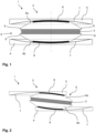
- Figs. 1 and 2 each show a lateral cross-section of a structural bearing 1 for protecting structures against shocks according to the invention in accordance with a first embodiment.
- the structural bearing 1 has a first damping device 2 and a second damping device 3.
- the first damping device 2 is designed for vibration isolation of shocks of a first type and the second damping device 3 is designed for vibration isolation of shocks of a second type. Thereby, the shocks of the first type differ significantly from the shocks of the second type.
- the first damping device 2 is an earthquake isolator in the form of a sliding pendulum bearing, in this case in particular a double sliding pendulum bearing.
- the sliding pendulum bearing has a lower bearing plate 4, an upper bearing plate 5 and a slider 6 located therebetween.
- the lower bearing plate 4 and the upper bearing plate 5 each include a main sliding surface on which the slider 6 can be deflected.
- the two main sliding surfaces are each concave in shape towards the slider 6.
- sliding sheets 7 are arranged on the respective main sliding surfaces so that the slider 6 can move along the main sliding surface in accordance with the required friction values.
- the slider 6 Towards the lower bearing plate 4 and the upper bearing plate 5, the slider 6 has a convexly shaped sliding surface, respectively, which is substantially complementary in shape to the respective main sliding surface of the lower bearing plate 4 and the upper bearing plate 5.
- the sliding surfaces of the slider 6 have a sliding material 8, so that the friction between the slider 6 and the lower bearing plate 4 and upper bearing plate 5 can be further reduced.
- the sliding pendulum bearing is designed for vibration isolation of substantially horizontal shocks from an earthquake load case of the structural bearing 1, see Fig. 2 .
- the slider 6 is deflected along the main sliding surfaces of the lower bearing plate 4 and the upper bearing plate 5. This allows the lower bearing plate 4 to move horizontally relative to the upper bearing plate 5.
- the isolation frequency of the sliding pendulum bearing is in a range of 0.2 Hz to 0.4 Hz.
- the second damping device 3 is designed as a structure-borne sound isolator.
- the second damping device 3 isolates micro shocks.
- the second damping device 3 is an elastomeric bearing.
- the elastomeric bearing is an elastomeric layer in the form of an elastomeric plate, which preferably includes polyurethane.
- the material HRB HS 12000 is used, which is suitable for particularly high permanent pressures.
- the elastomeric layer can also be reinforced so that the elastomeric bearing is additionally stabilized.
- the elastomeric bearing is designed for vibration isolation of shocks from a service condition load case of the structural bearing 1, see Fig. 1 . This applies to both essentially horizontal and vertical shocks. In other words, shocks can be isolated three-dimensionally. Due to the vibration isolation of relatively small shocks, the elastomeric bearing has an isolation frequency that is greater by at least the factor of 10 than the isolation frequency of the sliding pendulum bearing. In this case, the isolation frequency of the elastomeric bearing is in the range of 8 Hz to 15 Hz.
- the elastomeric bearing is arranged in the slider 6 of the sliding pendulum bearing.
- the slider 6 has an upper component 6a and a lower component 6b between which the elastomeric bearing is arranged.
- the upper component 6a and the lower component 6b are spatially spaced apart, so that there is no sound bridge between the upper component 6a and the lower component 6b.
- the elastomeric bearing forms a horizontal separation joint within the structural bearing 1 and, thus, can effectively minimize transmission of vibrations in the structure-borne sound and micro range from the lower structural bearing member to the upper structural bearing member.
- the upper component 6a and the lower component 6b are designed such that the respective diameter increases toward the elastomeric bearing.
- the surface pressure in the elastomeric bearing can be reduced relative to the surface pressure in the sliding surfaces between the slider 6 and the lower bearing plate 4 as well as upper bearing plate 5.
- the upper component 6a and the lower component 6b each have two lateral protrusions 9 to fix the elastomeric bearing between the protrusions 9.
- the elastomeric bearing may also be bonded to the upper and/or lower component 6a, 6b in order to achieve the desired fixation within the structural bearing 1.
- the dimensions of the elastomeric bearing can be reduced to a minimum. Furthermore, a separation plate dividing the elastomeric bearing and the sliding pendulum bearing into two isolation levels is no longer necessary.
- the elastomeric bearing is always evenly loaded, since the acting superimposed load of the structure is transferred at all times via the slider 6 from the upper bearing plate 5 to the lower bearing plate 4. Thus, too high local pressures and thrust stresses on the elastomeric bearing as well as a gaping joint in the area of the elastomeric bearing can be avoided.
- the elastomeric bearing can withstand even high force loads for a short period of time during the earthquake load case and remains operational.
- a single and simply designed structural bearing is provided that performs the functions of the structure-borne sound and shock protection during the service condition load case as well as the functions of the earthquake protection during the earthquake load case.
Landscapes
- Engineering & Computer Science (AREA)
- Architecture (AREA)
- Business, Economics & Management (AREA)
- Emergency Management (AREA)
- Environmental & Geological Engineering (AREA)
- Civil Engineering (AREA)
- Structural Engineering (AREA)
- Buildings Adapted To Withstand Abnormal External Influences (AREA)
- Vibration Prevention Devices (AREA)
- Vibration Dampers (AREA)
Description
- The present invention relates to a structural bearing for protecting structures against shocks.
- Such structural bearings are widely known from the prior art. On the one hand, structural bearings designed for earthquake protection are used herein. Earthquake isolators protect structures, such as buildings and bridges, which lie in the frequency range of high earthquake energy with respect to their first inherent frequency, against the effects of earthquakes by their very low coupling force in the horizontal direction. Typical earthquake isolators are sliding pendulum bearings and reinforced elastomeric bearings.
- Sliding pendulum bearings reduce the thrust forces on the structures by decoupling the structures from the earthquake accelerations in the horizontal direction by their deep horizontal coupling stiffness. In the vertical direction, sliding pendulum bearings do not create isolation of the structure against the vertical acceleration component of the earthquakes because the coupling stiffness of the sliding pendulum bearing in the vertical direction is too high. Most of the time, the sliding pendulum bearing does not act as an earthquake isolator because earthquakes occur very rarely. Instead, it performs the functions of a conventional structural bearing (absorbing the vertical load, transferring the wind load in the horizontal direction, absorbing non-earthquake horizontal displacements, absorbing the rotation of the structure).
- Reinforced elastomeric bearings with lead core (Lead Rubber Bearing (LRB)), without lead core (Low Damping Rubber Bearing (LDRB)), without lead core but with high elastomeric damping (High Damping Rubber Bearing (HDRB)) and flat sliders (flat surface slider (FSS)) together with a recentering spring element are also used for the horizontal earthquake isolation of structures. Just as with the sliding pendulum bearing, the horizontal earthquake isolation is also based on the deep horizontal coupling stiffness of the LRB, LDRB, HDRB or the FSS with recentering spring element. Likewise, these earthquake isolators increase the damping of the structure. The sliding pendulum bearing and the FSS increase the damping of the structure via the friction on the primary sliding surface. The LRB increases the structure damping via the hysteretic damping primarily of the lead core and secondarily of the elastomer. With a LDRB, the damping increase is naturally smaller. The difference between a sliding pendulum bearing and a LRB, LDRB, HDRB or FSS with recentering spring element is that the sliding pendulum bearing determines the pendulum period of the structure independently of the structure mass by its effective pendulum radius, whereas the LRB, LDRB, HDRB or FSS with recentering spring element determines the coupling stiffness by its stiffness. Thus, the coupling stiffness of the sliding pendulum bearing is determined by the structure mass and the pendulum period, while the pendulum period of the LRB, LDRB, HDRB or FSS with recentering spring element is determined by the structure mass and the stiffness of the LRB, LDRB, HDRB or FSS with recentering spring element.
- On the other hand, structural bearings are also used for structure-borne sound and shock protection. For the three-dimensional vibration protection of structures with regard to structure-borne sound and shock input, which affects the use of the structure, elastomeric bearings are generally used as point and strip bearings or as full-surface mounting or spring assemblies with viscous damper. The elastomeric bearings are either laid flat as mats between the structure and the ground (below and at the side) or arranged as point and strip bearings between walls and ceilings, wherein in both cases a continuous elastic separation joint is created between the upper part of the structure and the underlying part of the structure or the ground. Thereby, the entire separation joint does not necessarily have to be filled with elastomeric bearings. Even partial-surface mountings are possible. This arrangement of the bearings considerably reduces the transmission of vibrations in the audible and perceptible frequency range from the ground to the structure or from the lower to the upper floors. The elastomeric mats or bearings can be made of foamed polyurethane, for example.
- In the vibration isolation using spring assemblies with viscous damper, a horizontal separation joint is arranged in the structure in a similar way to point and strip bearings made of elastomer, by which the loads are transmitted by the elastic spring assemblies. Usually, the spring assemblies are not arranged over the entire surface of the joint, but rather at specific points. The spacing of the spring assemblies depends on the static conditions and can be, for example, 2 to 4 meters. Typically, the spring assemblies are made with parallel spiral springs and the viscous damper is designed as a pot damper.
- Such a vibration damper for a system for vibrationally isolating objects of large mass using a viscous or visco-elastic medium is disclosed, for example, in
EP 0 580 272 B1 . - The vibration isolation is created by the stiffness jump between the ground and the bearings, for example, between the lower part of the structure and the bearing, as well as between the bearing and the upper part of the structure. As a result of the stiffness jump, a part of the vibration energy is reflected at the joint and, thus, cannot reach the upper part of the structure. Due to the much higher dynamic stiffness of earthquake bearings in the vertical direction, this vibration isolation cannot be provided by the earthquake bearings. The lower the dynamic stiffness of the vibration isolation bearings compared to the ground and structure stiffness, the greater the isolation effect of the elastic mounting.
- The dynamic stiffness of the vibration isolation bearings necessary for a required isolation effect can be defined via the so-called tuning frequency of the mounting or also isolation frequency. The tuning frequency refers to the theoretical, vertical inherent frequency, which is determined by the part of the structure assumed to be a rigid mass above the bearing joint and the dynamic stiffness and damping of the elastic bearing joint. This simplified model approach is referred to as a single-mass oscillator. The ground is assumed to be infinitely stiff in this simplified consideration. The choice of the tuning frequency determines the vertical dynamic stiffness of the bearing joint per unit mass of the structure and is therefore the decisive parameter for dimensioning the elastic bearing joint.
- Usual values of the tuning frequency of the vibration isolations of buildings against structure-borne sound and micro shocks are in the range of about 8 Hz to about 15 Hz. These vibration isolation bearings must be able to absorb vertical amplitudes in the range of 1/100 mm and horizontal deformations of a few centimeters at most. In contrast, earthquake bearings generate a horizontal isolation frequency in the range of 0.2 Hz (isolation period duration 5 s) to 0.4 Hz (isolation period duration 2.5 s). Such earthquake bearings absorb horizontal displacements with amplitudes ranging from a few centimeters to more than one meter. The vertical stiffness of the earthquake bearings is many times greater than the stiffness of vibration isolation bearings with respect to structure-borne sound and micro shocks.
- Thus, if a structure is located in an earthquake-endangered region and structure-borne sound protection is also required, two isolation levels separated from each other by an intermediate plate must be provided in an expensive way due to these strongly different requirements regarding the stiffnesses and deformation capacities. Namely, one level for the horizontal earthquake isolation by means of sliding pendulum bearings, LRB, LDRB, HDRB or FSS with recentering spring element and one level for the three-dimensional structure-borne sound isolation by means of elastomeric bearings or spring assemblies with viscous damper.
CN 109 854 053 A discloses an example of a system with two isolation levels separated by an intermediate plate. - Thus, the object of the present invention is to provide an improved structural bearing which can isolate a wide range of shocks and at the same time is as simple as possible in design.
- According to the invention, the problem can be solved with a structural bearing according to
claim 1. Advantageous further embodiments of the invention can be derived fromdependent claims 2 to 25. - Thus, the structural bearing according to the invention for protecting structures against shocks has a first damping device and a second damping device. Thereby, the first damping device is designed for vibration isolation of shocks of a first type and the second damping device is designed for vibration isolation of shocks of a second type, wherein the shocks of the first type differ significantly from the shocks of the second type.
- With the structural bearing according to the invention, the functions of the two structural bearings, which have been designed and installed separately up to now, are combined in one device. On the one hand, this considerably simplifies the design of the overall construction with regard to the mounting and the protection of the structure against correspondingly different shocks. This applies in particular to the number and spatial dimensions of the components used for this purpose. On the other hand, a compact structural bearing is provided that can be installed in a single operation. Previously costly measures for separate successive installation of the different structural bearings with their corresponding damping functions can thus be avoided. In the end, a single structural bearing is provided that can cover a particularly wide range of shocks for protecting the structure.
- The first damping device and the second damping device can in principle be of any type. The decisive factor, however, is that the shocks of the first type to be isolated significantly differ from the shocks of the second type. In the present disclosure, the term "significantly" is understood as further defined by the dependent claims and in the following. The first damping device may be designed as, for example, a sliding pendulum bearing, a flat sliding bearing with recentering spring element or a reinforced earthquake elastomeric bearing. However, other types of structural bearings designed for load cases other than the earthquake load case are also conceivable. The second damping device, on the other hand, may include, for example, one or more elastomeric bearings that are used for various vibrations in the service condition load case of the structural bearing.
- The first damping device is an earthquake isolator and the second damping device is a structure-borne sound isolator. Thus, the first damping device isolates macro shocks. The second damping device, on the other hand, isolates micro shocks. By designing the first damping device as an earthquake isolator, large movements and corresponding shocks can be specifically isolated in an earthquake load case of the structural bearing. At the same time, the second damping device as a structure-borne sound protection enables particularly small and thus a significantly different type of shocks to be isolated in the service condition load case of the structural bearing. Thus, a particularly wide range of shocks can be isolated by the structural bearing.
- The second damping device is arranged in a component of the first damping device. With the arrangement of the second damping device in a component of the first damping device, a particularly compact structural bearing can be provided. Thereby, the previous functional principle of the first damping device is not affected. The second damping device is merely integrated into the first damping device and additional functions are added to the entire structural bearing. Moreover, the spatial dimensions of the second damping device can be reduced to a minimum. A separation of both damping devices in different isolation levels by further components is also no longer necessary. As a result, the structural bearing has a particularly simple design and at the same time can isolate a particularly wide range of shocks.
- Preferably, the second damping device has an isolation frequency that is greater by the factor of 10 or at least the factor of 10 than an isolation frequency of the first damping device. Due to the difference in magnitude by at least the factor of 10, the shocks of the first type differ from the shocks of the second type by at least one order of magnitude. Thus, significantly different shocks are isolated by the first damping device and the second damping device. Thus, a particularly wide range of shocks can be isolated by the structural bearing.
- Preferably, the isolation frequency of the first damping device is in the range of 0.2 Hz to 0.4 Hz and/or the isolation frequency of the second damping device is in the range of 8 Hz to 15 Hz. With the specified ranges, significantly different shocks are isolated by the first damping device and the second damping device. Thus, a particularly wide range of shocks can be isolated by the structural bearing.
- Preferably, the structural bearing is designed to isolate shocks three-dimensionally, preferably such that the first damping device isolates substantially horizontal shocks and the second damping device isolates substantially horizontal and vertical shocks. The three-dimensional vibration isolation or different design of the first damping device and the second damping device allows significantly different shocks to be isolated by the first damping device and the second damping device. Thus, a particularly wide range of shocks can be isolated by the structural bearing.
- Preferably, the first damping device is designed for vibration isolation of shocks from an earthquake load case, and the second damping device is designed for vibration isolation of shocks from a service condition load case of the structural bearing. With this design, the structural bearing can isolate the corresponding shocks in both an ordinary load case and an extraordinary load case. Thus, significantly different shocks are isolated by the first damping device and the second damping device. Thus, a particularly wide range of shocks can be isolated by the structural bearing.
- Preferably, the second damping device is arranged between two spatially spaced components of the first damping device. In this case, for example, the second damping device can be arranged between two previously separate components of the first damping device. However, a previously single component of the first damping device can also be divided into two components in order to arrange the second damping device therebetween. The spatial spacing ensures that there is no continuous sound bridge between the two spaced components of the first damping device. Both components are only connected via the intermediate second damping device. Thus, the second damping device or the structural bearing can isolate shocks of the second type particularly effectively.
- Advantageously, the first damping device is a sliding pendulum bearing, preferably a double sliding pendulum bearing. The sliding pendulum bearing can be particularly effective in isolating the corresponding horizontal shocks in an earthquake load case, see the above description of the prior art. The sliding pendulum bearing may be of any type. For example, the sliding pendulum bearing can be designed as a single sliding pendulum bearing, a double sliding pendulum bearing or an adaptive sliding pendulum bearing. These types of sliding pendulum bearings are widely known from the prior art, cf. corresponding solutions of the company Maurer Engineering GmbH.
- Preferably, the sliding pendulum bearing has an upper bearing plate, a lower bearing plate and a slider located therebetween, wherein the second damping device is arranged in the slider of the sliding pendulum bearing. This embodiment guarantees that the vertical load by the structure is always transferred centrally through the slider into the underlying foundation, regardless of the position of the slider on the main sliding surface. Thus, this also applies to the earthquake load case of the structural bearing, in which the slider may be fully deflected. Therefore, the surface pressure and thus the decisive dimensions, such as diameter and thickness, of the second damping device can be optimally adapted to the intended tuning frequency or isolation frequency of the second damping device. The non-centric load on the second damping device, especially in the earthquake load case, is only small in this solution, which avoids an uneven distribution of pressure in the second damping device or a gaping joint between the second damping device and the adjacent components. In addition, the slider generally represents the connection point with the smallest circumference in the vertical direction within the sliding pendulum bearing. Thus, the dimensions of the second damping device can also be reduced to a minimum. Hence, the structural bearing has a particularly compact and simple design.
- Preferably, the slider is divided into two parts and the second damping device is arranged between these two components of the slider. Advantageously, the slider is designed in such a way that the diameter of each of the two components of the slider increases towards the second damping device. As a result, the surface pressure in the second damping device can be reduced relative to the surface pressure in the sliding surfaces between the slider and the bearing plates.
- Preferably, the second damping device directly adjoins the first damping device. Due to the direct connection between the first damping device and the second damping device, the structural bearing has a particularly simple design. In particular, any separation or foundation plates to create two separate isolation levels for the first damping device and the second damping device are no longer necessary. Thus, the effort involved in manufacturing and installing the structural bearing can be considerably reduced.
- Preferably, the structural bearing has a load spreading plate which is arranged above the second damping device and preferably directly adjoins the second damping device. By means of the load spreading plate, the loads of the structure introduced vertically from above can be distributed over the entire surface of the second damping device in the service condition load case as well as in the earthquake load case of the structural bearing. Thus, the risk of too high local pressures and thrust stresses on the second damping device is also considerably reduced in this case. Likewise, even in the earthquake load case of the structural bearing, the occurrence of a gaping joint between the second damping device and the components adjoining it can be avoided. For example, the load spreading plate is made of concrete, steel or reinforced concrete.
- Advantageously, the second damping device has a V-shaped cross-section. In this case, preferably, the components arranged above and below the second damping device are complementary in shape thereto. Also in this case, due to the V-shaped design of the cross-section of the second damping device, too high local pressures and thrust stresses on the second damping device in the earthquake load case of the structural bearing can be avoided. In addition, the risk of a gaping joint between the second damping device and the components adjoining it is significantly reduced. The V-shaped design also includes variants in which only a portion of the cross-section is V-shaped. The second damping device may also be conical in shape.
- Preferably, the second damping device is an elastomeric bearing. Elastomeric bearings are particularly suitable for isolating structure-borne sound and shocks in the service condition load case of the structural bearing in the horizontal and vertical direction, this means three-dimensionally, see the above description of the prior art. In principle, the elastomeric bearing can be of any type. However, it must be designed for the service condition load case of the structural bearing. The use of several elastomeric bearings is also conceivable.
- Preferably, the elastomeric bearing has an elastomeric layer. Advantageously, the elastomeric bearing is an elastomeric layer. The elastomeric layer preferably incudes polyurethane, particularly preferably the material HRB HS 12000. The material HRB HS 12000 of the company Getzner is particularly suitable for high permanent pressures. In corresponding tests, a permissible short-term pressure of up to 52.9 MPa was determined. This means that damage to the elastomeric bearing can be avoided in the event of an earthquake load case of the structural bearing. The elastomeric bearing remains operational even after exceptionally large shocks, which are basically isolated by the first damping device.
- Advantageously, the elastomeric layer is reinforced. The reinforcement additionally stabilizes the elastomeric layer. Further, the force distribution within the elastomeric bearing can be controlled in a targeted manner. This means that damage to the elastomeric bearing can be avoided in the earthquake load case of the structural bearing. The elastomeric bearing remains operational even after exceptionally large shocks, which are basically isolated by the first damping device.
- Advantageously, the elastomeric layer has an elastomeric plate. Preferably, the elastomeric layer is an elastomeric plate. Particularly, the elastomeric plate is circular, rectangular, square and/or annular in shape. Elastomeric plates are particularly easy to manufacture and can be installed on site without great effort. Further, this makes the structural bearing compact and simple in design. By choosing the right shape, the elastomeric plate is optimally adapted to the spatial conditions in the structural bearing and corresponding requirements.
- In the following, advantageous embodiments of the present invention are schematically described with reference to the figures, wherein
- Fig. 1
- is a lateral cross-sectional view of a structural bearing according to the invention in the service condition load case according to a first embodiment; and
- Fig. 2
- is a lateral cross-sectional view of the structural bearing of
Fig.1 according to the invention in the earthquake load case. -
Figs. 1 and 2 each show a lateral cross-section of astructural bearing 1 for protecting structures against shocks according to the invention in accordance with a first embodiment. Thestructural bearing 1 has a first dampingdevice 2 and a second dampingdevice 3. The first dampingdevice 2 is designed for vibration isolation of shocks of a first type and the second dampingdevice 3 is designed for vibration isolation of shocks of a second type. Thereby, the shocks of the first type differ significantly from the shocks of the second type. - In the present example, the first damping
device 2 is an earthquake isolator in the form of a sliding pendulum bearing, in this case in particular a double sliding pendulum bearing. Thus, the first dampingdevice 2 isolates macro shocks. The sliding pendulum bearing has alower bearing plate 4, anupper bearing plate 5 and aslider 6 located therebetween. Thelower bearing plate 4 and theupper bearing plate 5 each include a main sliding surface on which theslider 6 can be deflected. The two main sliding surfaces are each concave in shape towards theslider 6. Furthermore, slidingsheets 7 are arranged on the respective main sliding surfaces so that theslider 6 can move along the main sliding surface in accordance with the required friction values. Towards thelower bearing plate 4 and theupper bearing plate 5, theslider 6 has a convexly shaped sliding surface, respectively, which is substantially complementary in shape to the respective main sliding surface of thelower bearing plate 4 and theupper bearing plate 5. The sliding surfaces of theslider 6 have a slidingmaterial 8, so that the friction between theslider 6 and thelower bearing plate 4 andupper bearing plate 5 can be further reduced. - The sliding pendulum bearing is designed for vibration isolation of substantially horizontal shocks from an earthquake load case of the
structural bearing 1, seeFig. 2 . In such a load case, theslider 6 is deflected along the main sliding surfaces of thelower bearing plate 4 and theupper bearing plate 5. This allows thelower bearing plate 4 to move horizontally relative to theupper bearing plate 5. Due to the vibration isolation of relatively large earthquake shocks, the isolation frequency of the sliding pendulum bearing is in a range of 0.2 Hz to 0.4 Hz. - The second damping
device 3 is designed as a structure-borne sound isolator. Thus, the second dampingdevice 3 isolates micro shocks. In the present example, the second dampingdevice 3 is an elastomeric bearing. The elastomeric bearing is an elastomeric layer in the form of an elastomeric plate, which preferably includes polyurethane. In this case, the material HRB HS 12000 is used, which is suitable for particularly high permanent pressures. Advantageously, the elastomeric layer can also be reinforced so that the elastomeric bearing is additionally stabilized. - The elastomeric bearing is designed for vibration isolation of shocks from a service condition load case of the
structural bearing 1, seeFig. 1 . This applies to both essentially horizontal and vertical shocks. In other words, shocks can be isolated three-dimensionally. Due to the vibration isolation of relatively small shocks, the elastomeric bearing has an isolation frequency that is greater by at least the factor of 10 than the isolation frequency of the sliding pendulum bearing. In this case, the isolation frequency of the elastomeric bearing is in the range of 8 Hz to 15 Hz. - As can be seen from
Figs. 1 and 2 , the elastomeric bearing is arranged in theslider 6 of the sliding pendulum bearing. In particular, theslider 6 has anupper component 6a and alower component 6b between which the elastomeric bearing is arranged. Further, theupper component 6a and thelower component 6b are spatially spaced apart, so that there is no sound bridge between theupper component 6a and thelower component 6b. Thus, the elastomeric bearing forms a horizontal separation joint within thestructural bearing 1 and, thus, can effectively minimize transmission of vibrations in the structure-borne sound and micro range from the lower structural bearing member to the upper structural bearing member. Theupper component 6a and thelower component 6b are designed such that the respective diameter increases toward the elastomeric bearing. Thereby, the surface pressure in the elastomeric bearing can be reduced relative to the surface pressure in the sliding surfaces between theslider 6 and thelower bearing plate 4 as well asupper bearing plate 5. Furthermore, theupper component 6a and thelower component 6b each have twolateral protrusions 9 to fix the elastomeric bearing between theprotrusions 9. Alternatively or additionally, the elastomeric bearing may also be bonded to the upper and/orlower component structural bearing 1. - By integrating the elastomeric bearing into the
slider 6 of the sliding pendulum bearing, the dimensions of the elastomeric bearing can be reduced to a minimum. Furthermore, a separation plate dividing the elastomeric bearing and the sliding pendulum bearing into two isolation levels is no longer necessary. In addition, even in the earthquake load case of thestructural bearing 1 or in a deflected position of theslider 6, the elastomeric bearing is always evenly loaded, since the acting superimposed load of the structure is transferred at all times via theslider 6 from theupper bearing plate 5 to thelower bearing plate 4. Thus, too high local pressures and thrust stresses on the elastomeric bearing as well as a gaping joint in the area of the elastomeric bearing can be avoided. By using the HRB HS 12000 material, the elastomeric bearing can withstand even high force loads for a short period of time during the earthquake load case and remains operational. In the end, a single and simply designed structural bearing is provided that performs the functions of the structure-borne sound and shock protection during the service condition load case as well as the functions of the earthquake protection during the earthquake load case. -
- 1
- Structural bearing
- 2
- First damping device
- 3
- Second damping device
- 4
- Lower bearing plate
- 5
- Upper bearing plate
- 6
- Slider
- 6a
- Upper component
- 6b
- Lower component
- 7
- Sliding sheet
- 8
- Sliding material
- 9
- Protrusion
- 11
- Load spreading plate
Claims (15)
- Structural bearing (1) for protecting structures against shocks, havinga first damping device (2) and a second damping device (3),wherein the first damping device (2) is designed for vibration isolation of shocks of a first type and the second damping device (3) is designed for vibration isolation of shocks of a second type, wherein the shocks of the first type differ significantly from the shocks of the second type, wherein the first damping device (2) is an earthquake isolator and the second damping device (3) is a structure-borne sound isolator,characterized in thatthe second damping device (3) is arranged in a component of the first damping device (2).
- Structural bearing (1) according to claim 1,
characterized in that
the second damping device (3) has an isolation frequency which is greater by at least the factor of 10 than an isolation frequency of the first damping device (2). - Structural bearing (1) according to claim 2,
characterized in that
the isolation frequency of the first damping device (2) is in the range from 0.2 Hz to 0.4 Hz and/or the isolation frequency of the second damping device (3) is in the range from 8 Hz to 15 Hz. - Structural bearing (1) according to one of the preceding claims,
characterized in that
the structural bearing (1) is designed to isolate shocks three-dimensionally, preferably such that the first damping device (2) isolates substantially horizontal shocks and the second damping device (3) isolates substantially horizontal and vertical shocks. - Structural bearing (1) according to one of the preceding claims,
characterized in that
the first damping device (2) is designed for vibration isolation of shocks from an earthquake load case, and the second damping device (3) is designed for vibration isolation of shocks from a service condition load case of the structural bearing (1). - Structural bearing (1) according to one of the preceding claims,
characterized in that
the second damping device (3) is arranged between two spatially spaced components of the first damping device (2). - Structural bearing (1) according to one of the preceding claims,
characterized in that
the first damping device (2) is a sliding pendulum bearing, preferably a double sliding pendulum bearing. - Structural bearing (1) according to claim 7,
characterized in that
the sliding pendulum bearing has an upper bearing plate (4), a lower bearing plate (5) and a slider (6) located therebetween, wherein the second damping device (3) is arranged in the slider (6) of the sliding pendulum bearing. - Structural bearing (1) according to one of the preceding claims,
characterized in that
the second damping device (3) directly adjoins the first damping device (2). - Structural bearing (1) according to one of the preceding claims,
characterized in that
the structural bearing (1) has a load spreading plate (11) which is arranged above the second damping device (3) and preferably directly adjoins the second damping device (3). - Structural bearing (1) according to one of the preceding claims,
characterized in that
the second damping device (3) has a V-shaped cross-section. - Structural bearing (1) according to one of the preceding claims,
characterized in that
the second damping device (3) is an elastomeric bearing. - Structural bearing (1) according to claim 12,
characterized in that
the elastomeric bearing has an elastomeric layer, which preferably includes polyurethane, particularly preferably the material HRB HS 12000. - Structural bearing (1) according to claim 13,
characterized in that
the elastomeric layer is reinforced. - Structural bearing (1) according to claim 13 or 14,
characterized in that
the elastomeric layer has an elastomeric plate, which is particularly circular, rectangular, square and/or annular in shape.
Priority Applications (2)
| Application Number | Priority Date | Filing Date | Title |
|---|---|---|---|
| HRP20241044TT HRP20241044T1 (en) | 2020-10-13 | 2021-10-13 | STRUCTURAL BEARINGS, INTENDED TO PROTECT STRUCTURES AGAINST IMPACTS |
| RS20240874A RS65817B1 (en) | 2020-10-13 | 2021-10-13 | Structural bearing for protecting structures against shocks |
Applications Claiming Priority (2)
| Application Number | Priority Date | Filing Date | Title |
|---|---|---|---|
| DE102020212920.7A DE102020212920A1 (en) | 2020-10-13 | 2020-10-13 | BUILDING BEARINGS TO PROTECT BUILDINGS AGAINST VIBRATION |
| PCT/EP2021/078326 WO2022079106A1 (en) | 2020-10-13 | 2021-10-13 | Structural bearing for protecting structures against shocks |
Publications (3)
| Publication Number | Publication Date |
|---|---|
| EP4165262A1 EP4165262A1 (en) | 2023-04-19 |
| EP4165262B1 true EP4165262B1 (en) | 2024-05-29 |
| EP4165262C0 EP4165262C0 (en) | 2024-05-29 |
Family
ID=78293970
Family Applications (1)
| Application Number | Title | Priority Date | Filing Date |
|---|---|---|---|
| EP21794495.8A Active EP4165262B1 (en) | 2020-10-13 | 2021-10-13 | Structural bearing for protecting structures against shocks |
Country Status (11)
| Country | Link |
|---|---|
| EP (1) | EP4165262B1 (en) |
| CN (1) | CN116324102A (en) |
| AU (1) | AU2021361097B2 (en) |
| CL (1) | CL2023000953A1 (en) |
| DE (1) | DE102020212920A1 (en) |
| ES (1) | ES2983538T3 (en) |
| HR (1) | HRP20241044T1 (en) |
| HU (1) | HUE067865T2 (en) |
| PH (1) | PH12023550157A1 (en) |
| RS (1) | RS65817B1 (en) |
| WO (1) | WO2022079106A1 (en) |
Family Cites Families (8)
| Publication number | Priority date | Publication date | Assignee | Title |
|---|---|---|---|---|
| DE4223786A1 (en) * | 1992-07-15 | 1994-01-20 | Gerb Schwingungsisolierungen | Vibration damper |
| US6324795B1 (en) | 1999-11-24 | 2001-12-04 | Ever-Level Foundation Systems, Inc. | Seismic isolation system between floor and foundation comprising a ball and socket joint and elastic or elastomeric element |
| DE10233804B3 (en) * | 2002-07-25 | 2004-02-26 | Isoloc Schwingungstechnik Gmbh | Vibration insulator used in the form of a suspension arrangement of a vehicle engine comprises a bearing block unit having elastomer bodies of an insulating element arrangement attached to support surfaces of a recess |
| KR100716088B1 (en) * | 2006-07-10 | 2007-05-08 | 주식회사 에스코알티에스 | Friction Vertical Vibration Damping Bearing |
| WO2012169669A1 (en) | 2011-06-08 | 2012-12-13 | Cho, Yeoung Cheol | Elastic device and mechanism to control horizontal displacement utilizing a horizontal component of elastic force and bridge bearing using the same |
| TWM426684U (en) * | 2011-12-09 | 2012-04-11 | Xun-Ren Zhuang | Seismic isolation bearing |
| CN205383398U (en) * | 2016-01-03 | 2016-07-13 | 山东科技大学 | Three -dimensional isolation bearing of antidumping |
| CN109854053A (en) * | 2019-01-28 | 2019-06-07 | 清华大学 | Intelligent 3D Seismic Isolation and Vibration Isolation System |
-
2020
- 2020-10-13 DE DE102020212920.7A patent/DE102020212920A1/en active Pending
-
2021
- 2021-10-13 RS RS20240874A patent/RS65817B1/en unknown
- 2021-10-13 HU HUE21794495A patent/HUE067865T2/en unknown
- 2021-10-13 CN CN202180064228.5A patent/CN116324102A/en active Pending
- 2021-10-13 EP EP21794495.8A patent/EP4165262B1/en active Active
- 2021-10-13 PH PH1/2023/550157A patent/PH12023550157A1/en unknown
- 2021-10-13 HR HRP20241044TT patent/HRP20241044T1/en unknown
- 2021-10-13 AU AU2021361097A patent/AU2021361097B2/en active Active
- 2021-10-13 WO PCT/EP2021/078326 patent/WO2022079106A1/en not_active Ceased
- 2021-10-13 ES ES21794495T patent/ES2983538T3/en active Active
-
2023
- 2023-03-30 CL CL2023000953A patent/CL2023000953A1/en unknown
Also Published As
| Publication number | Publication date |
|---|---|
| RS65817B1 (en) | 2024-09-30 |
| WO2022079106A1 (en) | 2022-04-21 |
| CL2023000953A1 (en) | 2023-09-15 |
| AU2021361097A1 (en) | 2023-02-23 |
| HUE067865T2 (en) | 2024-11-28 |
| EP4165262C0 (en) | 2024-05-29 |
| AU2021361097B2 (en) | 2024-06-13 |
| DE102020212920A1 (en) | 2022-04-14 |
| PH12023550157A1 (en) | 2024-03-18 |
| CN116324102A (en) | 2023-06-23 |
| EP4165262A1 (en) | 2023-04-19 |
| HRP20241044T1 (en) | 2024-11-08 |
| ES2983538T3 (en) | 2024-10-23 |
Similar Documents
| Publication | Publication Date | Title |
|---|---|---|
| EP2480737B1 (en) | Method and structure for damping movement in buildings | |
| KR101836164B1 (en) | Three-Dimensional Seismic Isolator equipped with Reduction Performance of Vertical Vibration | |
| CA2910914C (en) | Concrete sleeper and solid carriageway | |
| KR20110019587A (en) | Damper type isolation base | |
| US5386671A (en) | Stiffness decoupler for base isolation of structures | |
| US5657588A (en) | Earthquake shock damper for roadway pillars | |
| KR20110114265A (en) | Isolation Pile Cap and Isolation Pile Structure Using It | |
| CN114033065A (en) | Multifunctional device for isolating vibration and noise | |
| US6085471A (en) | Earthquake shock damper for roadway pillars | |
| AU2021361097B2 (en) | Structural bearing for protecting structures against shocks | |
| KR19990066356A (en) | Rubber feet for seismic isolation of structures | |
| HK40089719A (en) | Structural bearing for protecting structures against shocks | |
| HK40089719B (en) | Structural bearing for protecting structures against shocks | |
| KR20060084173A (en) | Base isolation bridge device for bridge using shape memory alloy | |
| JP2014034853A (en) | Bridge and vibration control damper for bridge | |
| JP4893061B2 (en) | Viscous vibration damping device and base-isolated building equipped with the same | |
| JPS63293340A (en) | Laminated rubber bearing | |
| JP7199995B2 (en) | locking mechanism | |
| KR20090033669A (en) | Vibration-absorbing bridge | |
| KR102487822B1 (en) | Hybrid isolation apparatus with reinforced vertical damping and horizontal multi-layer friction | |
| RU218716U1 (en) | STRUCTURE FOR VIBRATION PROTECTION OF BUILDINGS | |
| JP2021095921A (en) | Buffer and attachment structure of buffer | |
| JPH02248550A (en) | Device for exempting lightweight building from vibration | |
| JP2006226313A (en) | Seismic isolation device | |
| KR20180126657A (en) | A three dimension seismic isolator for maintaining easily |
Legal Events
| Date | Code | Title | Description |
|---|---|---|---|
| REG | Reference to a national code |
Ref country code: HR Ref legal event code: TUEP Ref document number: P20241044T Country of ref document: HR |
|
| STAA | Information on the status of an ep patent application or granted ep patent |
Free format text: STATUS: UNKNOWN |
|
| STAA | Information on the status of an ep patent application or granted ep patent |
Free format text: STATUS: THE INTERNATIONAL PUBLICATION HAS BEEN MADE |
|
| PUAI | Public reference made under article 153(3) epc to a published international application that has entered the european phase |
Free format text: ORIGINAL CODE: 0009012 |
|
| STAA | Information on the status of an ep patent application or granted ep patent |
Free format text: STATUS: REQUEST FOR EXAMINATION WAS MADE |
|
| 17P | Request for examination filed |
Effective date: 20230116 |
|
| AK | Designated contracting states |
Kind code of ref document: A1 Designated state(s): AL AT BE BG CH CY CZ DE DK EE ES FI FR GB GR HR HU IE IS IT LI LT LU LV MC MK MT NL NO PL PT RO RS SE SI SK SM TR |
|
| DAV | Request for validation of the european patent (deleted) | ||
| DAX | Request for extension of the european patent (deleted) | ||
| REG | Reference to a national code |
Ref country code: HK Ref legal event code: DE Ref document number: 40089719 Country of ref document: HK |
|
| GRAP | Despatch of communication of intention to grant a patent |
Free format text: ORIGINAL CODE: EPIDOSNIGR1 |
|
| STAA | Information on the status of an ep patent application or granted ep patent |
Free format text: STATUS: GRANT OF PATENT IS INTENDED |
|
| INTG | Intention to grant announced |
Effective date: 20240130 |
|
| GRAS | Grant fee paid |
Free format text: ORIGINAL CODE: EPIDOSNIGR3 |
|
| GRAA | (expected) grant |
Free format text: ORIGINAL CODE: 0009210 |
|
| STAA | Information on the status of an ep patent application or granted ep patent |
Free format text: STATUS: THE PATENT HAS BEEN GRANTED |
|
| AK | Designated contracting states |
Kind code of ref document: B1 Designated state(s): AL AT BE BG CH CY CZ DE DK EE ES FI FR GB GR HR HU IE IS IT LI LT LU LV MC MK MT NL NO PL PT RO RS SE SI SK SM TR |
|
| REG | Reference to a national code |
Ref country code: CH Ref legal event code: EP |
|
| REG | Reference to a national code |
Ref country code: IE Ref legal event code: FG4D |
|
| REG | Reference to a national code |
Ref country code: DE Ref legal event code: R096 Ref document number: 602021013931 Country of ref document: DE |
|
| U01 | Request for unitary effect filed |
Effective date: 20240621 |
|
| U07 | Unitary effect registered |
Designated state(s): AT BE BG DE DK EE FI FR IT LT LU LV MT NL PT SE SI Effective date: 20240703 |
|
| PG25 | Lapsed in a contracting state [announced via postgrant information from national office to epo] |
Ref country code: IS Free format text: LAPSE BECAUSE OF FAILURE TO SUBMIT A TRANSLATION OF THE DESCRIPTION OR TO PAY THE FEE WITHIN THE PRESCRIBED TIME-LIMIT Effective date: 20240929 |
|
| REG | Reference to a national code |
Ref country code: ES Ref legal event code: FG2A Ref document number: 2983538 Country of ref document: ES Kind code of ref document: T3 Effective date: 20241023 |
|
| REG | Reference to a national code |
Ref country code: GR Ref legal event code: EP Ref document number: 20240401914 Country of ref document: GR Effective date: 20241007 |
|
| REG | Reference to a national code |
Ref country code: HR Ref legal event code: ODRP Ref document number: P20241044T Country of ref document: HR Payment date: 20241008 Year of fee payment: 4 |
|
| PG25 | Lapsed in a contracting state [announced via postgrant information from national office to epo] |
Ref country code: PL Free format text: LAPSE BECAUSE OF FAILURE TO SUBMIT A TRANSLATION OF THE DESCRIPTION OR TO PAY THE FEE WITHIN THE PRESCRIBED TIME-LIMIT Effective date: 20240529 |
|
| PG25 | Lapsed in a contracting state [announced via postgrant information from national office to epo] |
Ref country code: PL Free format text: LAPSE BECAUSE OF FAILURE TO SUBMIT A TRANSLATION OF THE DESCRIPTION OR TO PAY THE FEE WITHIN THE PRESCRIBED TIME-LIMIT Effective date: 20240529 Ref country code: NO Free format text: LAPSE BECAUSE OF FAILURE TO SUBMIT A TRANSLATION OF THE DESCRIPTION OR TO PAY THE FEE WITHIN THE PRESCRIBED TIME-LIMIT Effective date: 20240829 Ref country code: IS Free format text: LAPSE BECAUSE OF FAILURE TO SUBMIT A TRANSLATION OF THE DESCRIPTION OR TO PAY THE FEE WITHIN THE PRESCRIBED TIME-LIMIT Effective date: 20240929 |
|
| REG | Reference to a national code |
Ref country code: HR Ref legal event code: T1PR Ref document number: P20241044 Country of ref document: HR |
|
| REG | Reference to a national code |
Ref country code: HU Ref legal event code: AG4A Ref document number: E067865 Country of ref document: HU |
|
| U20 | Renewal fee for the european patent with unitary effect paid |
Year of fee payment: 4 Effective date: 20241028 |
|
| PG25 | Lapsed in a contracting state [announced via postgrant information from national office to epo] |
Ref country code: CZ Free format text: LAPSE BECAUSE OF FAILURE TO SUBMIT A TRANSLATION OF THE DESCRIPTION OR TO PAY THE FEE WITHIN THE PRESCRIBED TIME-LIMIT Effective date: 20240529 |
|
| PG25 | Lapsed in a contracting state [announced via postgrant information from national office to epo] |
Ref country code: SK Free format text: LAPSE BECAUSE OF FAILURE TO SUBMIT A TRANSLATION OF THE DESCRIPTION OR TO PAY THE FEE WITHIN THE PRESCRIBED TIME-LIMIT Effective date: 20240529 |
|
| PG25 | Lapsed in a contracting state [announced via postgrant information from national office to epo] |
Ref country code: SM Free format text: LAPSE BECAUSE OF FAILURE TO SUBMIT A TRANSLATION OF THE DESCRIPTION OR TO PAY THE FEE WITHIN THE PRESCRIBED TIME-LIMIT Effective date: 20240529 |
|
| PG25 | Lapsed in a contracting state [announced via postgrant information from national office to epo] |
Ref country code: SM Free format text: LAPSE BECAUSE OF FAILURE TO SUBMIT A TRANSLATION OF THE DESCRIPTION OR TO PAY THE FEE WITHIN THE PRESCRIBED TIME-LIMIT Effective date: 20240529 Ref country code: SK Free format text: LAPSE BECAUSE OF FAILURE TO SUBMIT A TRANSLATION OF THE DESCRIPTION OR TO PAY THE FEE WITHIN THE PRESCRIBED TIME-LIMIT Effective date: 20240529 Ref country code: CZ Free format text: LAPSE BECAUSE OF FAILURE TO SUBMIT A TRANSLATION OF THE DESCRIPTION OR TO PAY THE FEE WITHIN THE PRESCRIBED TIME-LIMIT Effective date: 20240529 |
|
| PLBE | No opposition filed within time limit |
Free format text: ORIGINAL CODE: 0009261 |
|
| STAA | Information on the status of an ep patent application or granted ep patent |
Free format text: STATUS: NO OPPOSITION FILED WITHIN TIME LIMIT |
|
| 26N | No opposition filed |
Effective date: 20250303 |
|
| PG25 | Lapsed in a contracting state [announced via postgrant information from national office to epo] |
Ref country code: MC Free format text: LAPSE BECAUSE OF FAILURE TO SUBMIT A TRANSLATION OF THE DESCRIPTION OR TO PAY THE FEE WITHIN THE PRESCRIBED TIME-LIMIT Effective date: 20240529 |
|
| PG25 | Lapsed in a contracting state [announced via postgrant information from national office to epo] |
Ref country code: IE Free format text: LAPSE BECAUSE OF NON-PAYMENT OF DUE FEES Effective date: 20241013 |
|
| PGFP | Annual fee paid to national office [announced via postgrant information from national office to epo] |
Ref country code: RS Payment date: 20250930 Year of fee payment: 5 |
|
| REG | Reference to a national code |
Ref country code: CH Ref legal event code: U11 Free format text: ST27 STATUS EVENT CODE: U-0-0-U10-U11 (AS PROVIDED BY THE NATIONAL OFFICE) Effective date: 20251101 |
|
| REG | Reference to a national code |
Ref country code: HR Ref legal event code: ODRP Ref document number: P20241044 Country of ref document: HR Payment date: 20251003 Year of fee payment: 5 |
|
| PGFP | Annual fee paid to national office [announced via postgrant information from national office to epo] |
Ref country code: HU Payment date: 20251010 Year of fee payment: 5 |
|
| U20 | Renewal fee for the european patent with unitary effect paid |
Year of fee payment: 5 Effective date: 20251027 |
|
| PGFP | Annual fee paid to national office [announced via postgrant information from national office to epo] |
Ref country code: HR Payment date: 20251003 Year of fee payment: 5 |
|
| PGFP | Annual fee paid to national office [announced via postgrant information from national office to epo] |
Ref country code: TR Payment date: 20251006 Year of fee payment: 5 Ref country code: GR Payment date: 20251021 Year of fee payment: 5 |
|
| PGFP | Annual fee paid to national office [announced via postgrant information from national office to epo] |
Ref country code: CH Payment date: 20251101 Year of fee payment: 5 |
|
| PGFP | Annual fee paid to national office [announced via postgrant information from national office to epo] |
Ref country code: CY Payment date: 20250930 Year of fee payment: 5 |
|
| PGFP | Annual fee paid to national office [announced via postgrant information from national office to epo] |
Ref country code: RO Payment date: 20251003 Year of fee payment: 5 |
|
| PGFP | Annual fee paid to national office [announced via postgrant information from national office to epo] |
Ref country code: ES Payment date: 20251114 Year of fee payment: 5 |