EP4164860B1 - Method of detecting and compensating for a non-operational mold cavity in an injection molding apparatus - Google Patents
Method of detecting and compensating for a non-operational mold cavity in an injection molding apparatus Download PDFInfo
- Publication number
- EP4164860B1 EP4164860B1 EP21731663.7A EP21731663A EP4164860B1 EP 4164860 B1 EP4164860 B1 EP 4164860B1 EP 21731663 A EP21731663 A EP 21731663A EP 4164860 B1 EP4164860 B1 EP 4164860B1
- Authority
- EP
- European Patent Office
- Prior art keywords
- injection molding
- parameter
- expected
- mold cavities
- pressure
- Prior art date
- Legal status (The legal status is an assumption and is not a legal conclusion. Google has not performed a legal analysis and makes no representation as to the accuracy of the status listed.)
- Active
Links
Images


Classifications
-
- B—PERFORMING OPERATIONS; TRANSPORTING
- B29—WORKING OF PLASTICS; WORKING OF SUBSTANCES IN A PLASTIC STATE IN GENERAL
- B29C—SHAPING OR JOINING OF PLASTICS; SHAPING OF MATERIAL IN A PLASTIC STATE, NOT OTHERWISE PROVIDED FOR; AFTER-TREATMENT OF THE SHAPED PRODUCTS, e.g. REPAIRING
- B29C45/00—Injection moulding, i.e. forcing the required volume of moulding material through a nozzle into a closed mould; Apparatus therefor
- B29C45/17—Component parts, details or accessories; Auxiliary operations
- B29C45/76—Measuring, controlling or regulating
- B29C45/7693—Measuring, controlling or regulating using rheological models of the material in the mould, e.g. finite elements method
-
- B—PERFORMING OPERATIONS; TRANSPORTING
- B29—WORKING OF PLASTICS; WORKING OF SUBSTANCES IN A PLASTIC STATE IN GENERAL
- B29C—SHAPING OR JOINING OF PLASTICS; SHAPING OF MATERIAL IN A PLASTIC STATE, NOT OTHERWISE PROVIDED FOR; AFTER-TREATMENT OF THE SHAPED PRODUCTS, e.g. REPAIRING
- B29C45/00—Injection moulding, i.e. forcing the required volume of moulding material through a nozzle into a closed mould; Apparatus therefor
- B29C45/17—Component parts, details or accessories; Auxiliary operations
- B29C45/26—Moulds
-
- B—PERFORMING OPERATIONS; TRANSPORTING
- B29—WORKING OF PLASTICS; WORKING OF SUBSTANCES IN A PLASTIC STATE IN GENERAL
- B29C—SHAPING OR JOINING OF PLASTICS; SHAPING OF MATERIAL IN A PLASTIC STATE, NOT OTHERWISE PROVIDED FOR; AFTER-TREATMENT OF THE SHAPED PRODUCTS, e.g. REPAIRING
- B29C45/00—Injection moulding, i.e. forcing the required volume of moulding material through a nozzle into a closed mould; Apparatus therefor
- B29C45/17—Component parts, details or accessories; Auxiliary operations
- B29C45/46—Means for plasticising or homogenising the moulding material or forcing it into the mould
- B29C45/47—Means for plasticising or homogenising the moulding material or forcing it into the mould using screws
- B29C45/50—Axially movable screw
-
- B—PERFORMING OPERATIONS; TRANSPORTING
- B29—WORKING OF PLASTICS; WORKING OF SUBSTANCES IN A PLASTIC STATE IN GENERAL
- B29C—SHAPING OR JOINING OF PLASTICS; SHAPING OF MATERIAL IN A PLASTIC STATE, NOT OTHERWISE PROVIDED FOR; AFTER-TREATMENT OF THE SHAPED PRODUCTS, e.g. REPAIRING
- B29C45/00—Injection moulding, i.e. forcing the required volume of moulding material through a nozzle into a closed mould; Apparatus therefor
- B29C45/17—Component parts, details or accessories; Auxiliary operations
- B29C45/76—Measuring, controlling or regulating
- B29C45/7613—Measuring, controlling or regulating the termination of flow of material into the mould
-
- B—PERFORMING OPERATIONS; TRANSPORTING
- B29—WORKING OF PLASTICS; WORKING OF SUBSTANCES IN A PLASTIC STATE IN GENERAL
- B29C—SHAPING OR JOINING OF PLASTICS; SHAPING OF MATERIAL IN A PLASTIC STATE, NOT OTHERWISE PROVIDED FOR; AFTER-TREATMENT OF THE SHAPED PRODUCTS, e.g. REPAIRING
- B29C45/00—Injection moulding, i.e. forcing the required volume of moulding material through a nozzle into a closed mould; Apparatus therefor
- B29C45/17—Component parts, details or accessories; Auxiliary operations
- B29C45/76—Measuring, controlling or regulating
- B29C45/768—Detecting defective moulding conditions
-
- B—PERFORMING OPERATIONS; TRANSPORTING
- B29—WORKING OF PLASTICS; WORKING OF SUBSTANCES IN A PLASTIC STATE IN GENERAL
- B29C—SHAPING OR JOINING OF PLASTICS; SHAPING OF MATERIAL IN A PLASTIC STATE, NOT OTHERWISE PROVIDED FOR; AFTER-TREATMENT OF THE SHAPED PRODUCTS, e.g. REPAIRING
- B29C45/00—Injection moulding, i.e. forcing the required volume of moulding material through a nozzle into a closed mould; Apparatus therefor
- B29C45/17—Component parts, details or accessories; Auxiliary operations
- B29C45/76—Measuring, controlling or regulating
- B29C45/77—Measuring, controlling or regulating of velocity or pressure of moulding material
-
- B—PERFORMING OPERATIONS; TRANSPORTING
- B29—WORKING OF PLASTICS; WORKING OF SUBSTANCES IN A PLASTIC STATE IN GENERAL
- B29C—SHAPING OR JOINING OF PLASTICS; SHAPING OF MATERIAL IN A PLASTIC STATE, NOT OTHERWISE PROVIDED FOR; AFTER-TREATMENT OF THE SHAPED PRODUCTS, e.g. REPAIRING
- B29C45/00—Injection moulding, i.e. forcing the required volume of moulding material through a nozzle into a closed mould; Apparatus therefor
- B29C45/17—Component parts, details or accessories; Auxiliary operations
- B29C45/76—Measuring, controlling or regulating
- B29C45/80—Measuring, controlling or regulating of relative position of mould parts
-
- B—PERFORMING OPERATIONS; TRANSPORTING
- B29—WORKING OF PLASTICS; WORKING OF SUBSTANCES IN A PLASTIC STATE IN GENERAL
- B29C—SHAPING OR JOINING OF PLASTICS; SHAPING OF MATERIAL IN A PLASTIC STATE, NOT OTHERWISE PROVIDED FOR; AFTER-TREATMENT OF THE SHAPED PRODUCTS, e.g. REPAIRING
- B29C45/00—Injection moulding, i.e. forcing the required volume of moulding material through a nozzle into a closed mould; Apparatus therefor
- B29C45/17—Component parts, details or accessories; Auxiliary operations
- B29C45/26—Moulds
- B29C2045/2683—Plurality of independent mould cavities in a single mould
-
- B—PERFORMING OPERATIONS; TRANSPORTING
- B29—WORKING OF PLASTICS; WORKING OF SUBSTANCES IN A PLASTIC STATE IN GENERAL
- B29C—SHAPING OR JOINING OF PLASTICS; SHAPING OF MATERIAL IN A PLASTIC STATE, NOT OTHERWISE PROVIDED FOR; AFTER-TREATMENT OF THE SHAPED PRODUCTS, e.g. REPAIRING
- B29C2945/00—Indexing scheme relating to injection moulding, i.e. forcing the required volume of moulding material through a nozzle into a closed mould
- B29C2945/76—Measuring, controlling or regulating
- B29C2945/76003—Measured parameter
- B29C2945/76006—Pressure
-
- B—PERFORMING OPERATIONS; TRANSPORTING
- B29—WORKING OF PLASTICS; WORKING OF SUBSTANCES IN A PLASTIC STATE IN GENERAL
- B29C—SHAPING OR JOINING OF PLASTICS; SHAPING OF MATERIAL IN A PLASTIC STATE, NOT OTHERWISE PROVIDED FOR; AFTER-TREATMENT OF THE SHAPED PRODUCTS, e.g. REPAIRING
- B29C2945/00—Indexing scheme relating to injection moulding, i.e. forcing the required volume of moulding material through a nozzle into a closed mould
- B29C2945/76—Measuring, controlling or regulating
- B29C2945/76003—Measured parameter
- B29C2945/76083—Position
-
- B—PERFORMING OPERATIONS; TRANSPORTING
- B29—WORKING OF PLASTICS; WORKING OF SUBSTANCES IN A PLASTIC STATE IN GENERAL
- B29C—SHAPING OR JOINING OF PLASTICS; SHAPING OF MATERIAL IN A PLASTIC STATE, NOT OTHERWISE PROVIDED FOR; AFTER-TREATMENT OF THE SHAPED PRODUCTS, e.g. REPAIRING
- B29C2945/00—Indexing scheme relating to injection moulding, i.e. forcing the required volume of moulding material through a nozzle into a closed mould
- B29C2945/76—Measuring, controlling or regulating
- B29C2945/76003—Measured parameter
- B29C2945/76167—Presence, absence of objects
-
- B—PERFORMING OPERATIONS; TRANSPORTING
- B29—WORKING OF PLASTICS; WORKING OF SUBSTANCES IN A PLASTIC STATE IN GENERAL
- B29C—SHAPING OR JOINING OF PLASTICS; SHAPING OF MATERIAL IN A PLASTIC STATE, NOT OTHERWISE PROVIDED FOR; AFTER-TREATMENT OF THE SHAPED PRODUCTS, e.g. REPAIRING
- B29C2945/00—Indexing scheme relating to injection moulding, i.e. forcing the required volume of moulding material through a nozzle into a closed mould
- B29C2945/76—Measuring, controlling or regulating
- B29C2945/76177—Location of measurement
- B29C2945/7618—Injection unit
- B29C2945/76187—Injection unit screw
-
- B—PERFORMING OPERATIONS; TRANSPORTING
- B29—WORKING OF PLASTICS; WORKING OF SUBSTANCES IN A PLASTIC STATE IN GENERAL
- B29C—SHAPING OR JOINING OF PLASTICS; SHAPING OF MATERIAL IN A PLASTIC STATE, NOT OTHERWISE PROVIDED FOR; AFTER-TREATMENT OF THE SHAPED PRODUCTS, e.g. REPAIRING
- B29C2945/00—Indexing scheme relating to injection moulding, i.e. forcing the required volume of moulding material through a nozzle into a closed mould
- B29C2945/76—Measuring, controlling or regulating
- B29C2945/76177—Location of measurement
- B29C2945/7618—Injection unit
- B29C2945/7621—Injection unit nozzle
-
- B—PERFORMING OPERATIONS; TRANSPORTING
- B29—WORKING OF PLASTICS; WORKING OF SUBSTANCES IN A PLASTIC STATE IN GENERAL
- B29C—SHAPING OR JOINING OF PLASTICS; SHAPING OF MATERIAL IN A PLASTIC STATE, NOT OTHERWISE PROVIDED FOR; AFTER-TREATMENT OF THE SHAPED PRODUCTS, e.g. REPAIRING
- B29C2945/00—Indexing scheme relating to injection moulding, i.e. forcing the required volume of moulding material through a nozzle into a closed mould
- B29C2945/76—Measuring, controlling or regulating
- B29C2945/76177—Location of measurement
- B29C2945/76254—Mould
- B29C2945/76257—Mould cavity
-
- B—PERFORMING OPERATIONS; TRANSPORTING
- B29—WORKING OF PLASTICS; WORKING OF SUBSTANCES IN A PLASTIC STATE IN GENERAL
- B29C—SHAPING OR JOINING OF PLASTICS; SHAPING OF MATERIAL IN A PLASTIC STATE, NOT OTHERWISE PROVIDED FOR; AFTER-TREATMENT OF THE SHAPED PRODUCTS, e.g. REPAIRING
- B29C2945/00—Indexing scheme relating to injection moulding, i.e. forcing the required volume of moulding material through a nozzle into a closed mould
- B29C2945/76—Measuring, controlling or regulating
- B29C2945/76344—Phase or stage of measurement
- B29C2945/76381—Injection
-
- B—PERFORMING OPERATIONS; TRANSPORTING
- B29—WORKING OF PLASTICS; WORKING OF SUBSTANCES IN A PLASTIC STATE IN GENERAL
- B29C—SHAPING OR JOINING OF PLASTICS; SHAPING OF MATERIAL IN A PLASTIC STATE, NOT OTHERWISE PROVIDED FOR; AFTER-TREATMENT OF THE SHAPED PRODUCTS, e.g. REPAIRING
- B29C2945/00—Indexing scheme relating to injection moulding, i.e. forcing the required volume of moulding material through a nozzle into a closed mould
- B29C2945/76—Measuring, controlling or regulating
- B29C2945/76494—Controlled parameter
- B29C2945/76498—Pressure
-
- B—PERFORMING OPERATIONS; TRANSPORTING
- B29—WORKING OF PLASTICS; WORKING OF SUBSTANCES IN A PLASTIC STATE IN GENERAL
- B29C—SHAPING OR JOINING OF PLASTICS; SHAPING OF MATERIAL IN A PLASTIC STATE, NOT OTHERWISE PROVIDED FOR; AFTER-TREATMENT OF THE SHAPED PRODUCTS, e.g. REPAIRING
- B29C2945/00—Indexing scheme relating to injection moulding, i.e. forcing the required volume of moulding material through a nozzle into a closed mould
- B29C2945/76—Measuring, controlling or regulating
- B29C2945/76494—Controlled parameter
- B29C2945/76568—Position
-
- B—PERFORMING OPERATIONS; TRANSPORTING
- B29—WORKING OF PLASTICS; WORKING OF SUBSTANCES IN A PLASTIC STATE IN GENERAL
- B29C—SHAPING OR JOINING OF PLASTICS; SHAPING OF MATERIAL IN A PLASTIC STATE, NOT OTHERWISE PROVIDED FOR; AFTER-TREATMENT OF THE SHAPED PRODUCTS, e.g. REPAIRING
- B29C2945/00—Indexing scheme relating to injection moulding, i.e. forcing the required volume of moulding material through a nozzle into a closed mould
- B29C2945/76—Measuring, controlling or regulating
- B29C2945/76494—Controlled parameter
- B29C2945/76595—Velocity
-
- B—PERFORMING OPERATIONS; TRANSPORTING
- B29—WORKING OF PLASTICS; WORKING OF SUBSTANCES IN A PLASTIC STATE IN GENERAL
- B29C—SHAPING OR JOINING OF PLASTICS; SHAPING OF MATERIAL IN A PLASTIC STATE, NOT OTHERWISE PROVIDED FOR; AFTER-TREATMENT OF THE SHAPED PRODUCTS, e.g. REPAIRING
- B29C2945/00—Indexing scheme relating to injection moulding, i.e. forcing the required volume of moulding material through a nozzle into a closed mould
- B29C2945/76—Measuring, controlling or regulating
- B29C2945/76655—Location of control
- B29C2945/76658—Injection unit
- B29C2945/76665—Injection unit screw
-
- B—PERFORMING OPERATIONS; TRANSPORTING
- B29—WORKING OF PLASTICS; WORKING OF SUBSTANCES IN A PLASTIC STATE IN GENERAL
- B29C—SHAPING OR JOINING OF PLASTICS; SHAPING OF MATERIAL IN A PLASTIC STATE, NOT OTHERWISE PROVIDED FOR; AFTER-TREATMENT OF THE SHAPED PRODUCTS, e.g. REPAIRING
- B29C2945/00—Indexing scheme relating to injection moulding, i.e. forcing the required volume of moulding material through a nozzle into a closed mould
- B29C2945/76—Measuring, controlling or regulating
- B29C2945/76822—Phase or stage of control
- B29C2945/76859—Injection
-
- B—PERFORMING OPERATIONS; TRANSPORTING
- B29—WORKING OF PLASTICS; WORKING OF SUBSTANCES IN A PLASTIC STATE IN GENERAL
- B29C—SHAPING OR JOINING OF PLASTICS; SHAPING OF MATERIAL IN A PLASTIC STATE, NOT OTHERWISE PROVIDED FOR; AFTER-TREATMENT OF THE SHAPED PRODUCTS, e.g. REPAIRING
- B29C2945/00—Indexing scheme relating to injection moulding, i.e. forcing the required volume of moulding material through a nozzle into a closed mould
- B29C2945/76—Measuring, controlling or regulating
- B29C2945/76929—Controlling method
- B29C2945/76939—Using stored or historical data sets
- B29C2945/76943—Using stored or historical data sets compare with thresholds
Definitions
- the present disclosure generally relates to apparatuses and methods for injection molding and, more particularly, to apparatuses and methods for detecting and compensating for non-operational (e.g., blocked) cavities within a mold.
- Injection molding is a technology commonly used for high-volume manufacturing of parts made of thermoplastic material.
- a thermoplastic resin most often in the form of small beads or pellets, is introduced to an injection molding apparatus that melts the resin beads under heat and pressure.
- the now-molten resin is forcefully injected into a mold cavity having a particular cavity shape.
- the injected plastic is held under pressure in the mold cavity, cooled, and then removed as a solidified part having a shape that essentially duplicates the cavity shape of the mold.
- the mold itself may have a single cavity or multiple cavities.
- An injection molding cycle can include the steps of (1) melting a shot of polymeric material; (2) clamping together two (or more) portions of a mold, such as a mold core and a mold cavity plate, that together form the mold walls that define one or more mold cavities (typically while the mold walls are in a cool condition relative to the temperature to which the molten thermoplastic material is heated prior to injection into the mold cavity); (3) injecting molten polymeric material into the one or more mold cavities; (4) packing or holding the material, i.e., applying one or more set pressures to the material, after the mold is full, to ensure adequate densification within the cavity and wait for material solidification in the gate(s) or runner(s) to prevent the material from flowing in the opposite direction through the gate(s) or runner(s); (5) waiting some period of time until the molded polymeric material cools to a temperature sufficient to eject the part, i.e.
- JPS57115835A discloses a constant current power source, resistors and switches turned off and on responding to the conditions of resin in metal molds, constitute a monitoring system.
- the circuit including the resistor closes, thereby reducing to a 1/2 the current through the resistor.
- the circuits including the resistors close, reducing to a the current through the resistor.
- a controlling unit operating on the current received through the resistor contained in a transfer mold forming machine or externally connected thereto, constant speed potting can be effected lasting until the last metal mold is filled up with resin.
- JPH0760807A discloses cavities corresponding to the shapes of a plurality of bottomed containers are formed between a stationary mold and a movable mold.
- a sprue to which the nozzle of an injection molder is connected, is provided in the stationary mold.
- molten resin is poured by advancing the screw of the injection molder and, after that, dwelled for a certain period of time. By measuring the position of the screw after the release of dwelling, the abnormality in molding process is detected.
- the present disclosure describes a method of detecting at least one non-operational cavity in a multi-cavity mold during an injection molding cycle and automatically adjusting a process parameter of the injection molding cycle to compensate for the at least one non-operational cavity.
- Embodiments of the present invention generally relate to systems, machines, products, and methods of producing parts by injection molding and, more specifically, to systems, parts, and methods of detecting a non-operational cavity in a multi-cavity mold and automatically adjusting a process parameter to continue producing quality parts despite at least one cavity being non-operational.
- the phrase "process parameter" generally refers to a parameter of an injection molding apparatus that is at least partially responsible for the quality of a part created using a multi-cavity mold of that injection molding apparatus.
- the "process parameter” can include, but is not limited to, a nozzle pressure of an injection nozzle of the injection molding apparatus, a position of a reciprocating screw disposed in the injection molding apparatus, a cushion of the molten thermoplastic material, a melt pressure of a molten thermoplastic material being injected into the multi-cavity mold of the injection molding apparatus, an expected travel of the reciprocating screw, a shot size of the thermoplastic material, an end-of-fill transition point such as a screw position set point and a time set point, or any other parameter that could affect the operation of the injection molding apparatus during the cycle or the quality of the product.
- the term "cavity percent fill” can refer to the percentage of the cavity that is filled on a volumetric basis, or the percentage of the cavity that is filled in relation to weight or mass of the molten material. For example, if a cavity is 95% filled, then the total volume of the mold cavity that is filled is 95% of the total volumetric capacity of the mold cavity. Alternatively, if a cavity is 95% filled, then the total weight of the material in the mold is equal to 95% of the weight specifications of a full part.
- the term “cushion” refers to a distance from a front of a check ring to an end of a barrel at an end of the injection molding cycle.
- the cushion is generally based on both the mold volume and the target shot size. For a given mold with constant volume, when the target shot size is increased, the cushion will increase as well. Conversely, when the target shot size is decreased, the cushion will decrease as well.
- cycle time is defined as a single iteration of an injection molding process that is required to fully form an injection molded part. Cycle time includes the collective time it takes to perform the steps of advancing molten thermoplastic material into a mold cavity, substantially filling the mold cavity with thermoplastic material, packing and/or holding pressure on the thermoplastic material within the cavity, cooling the thermoplastic material, separating first and second mold sides to expose the cooled thermoplastic material, removing the thermoplastic material, and closing the first and second mold sides.
- thermoplastic material when used with respect to a mold cavity including thermoplastic material, are interchangeable and both terms mean that thermoplastic material has reached the maximum volumetric capacity of the mold cavity.
- flow front refers to a leading edge of a shot of molten polymeric material, as experienced by the surfaces of the mold that define a mold cavity, as the molten polymeric material is progressing from a nozzle or gate of the mold cavity (i.e., a point or points of introduction of the molten polymeric material into the mold cavity) toward, and ultimately to, an end-of-fill location of the mold cavity.
- flow rate generally refers to the volumetric flow rate of polymer as measured at the injection nozzle. This flow rate can be calculated based on the injection rate, the compressibility of the thermoplastic material, the pressure experienced by thermoplastic material as measured at the injection nozzle, and the cross sectional area of the nozzle, or measured with a suitable sensor located in the injection nozzle.
- melt temperature generally refers to the temperature of the polymer that is maintained in the injection unit/barrel, and in the material feed system when a hot runner system is used, which keeps the polymer in a molten state.
- the melt temperature varies by material. However, a desired melt temperature is generally understood to fall within the ranges recommended by the material manufacturer.
- the term "mold simulator” is defined as a software simulator such as AUTODESK ® MOLDFLOW ® ADVISER (TRADEMARK) by AUTODESK, INC., San Rafeal, California, used to simulate or model an injection molding cycle to determine a predicted or expected parameter of the injection molding apparatus during the subsequent actual injection molding cycle performed using the injection molding apparatus.
- the "mold simulator” may, for example, determine an expected position of the reciprocating screw or an expected location of a flow front of the molten thermoplastic material at fixed intervals of time.
- the “mold simulator” may also generate a pressure profile according to which an injection molding system might operate to achieve a selected flow front velocity profile.
- the "mold simulator” may produce a model of a mold cavity with contour lines spaced along the length thereof, with the exact spacing depending on the selected profile.
- the contour lines may, for example, depict a flow front velocity throughout filling of the mold cavity that does not exceed a desired maximum or a flow front velocity that varies throughout filling of the mold cavity based on a custom flow front profile.
- production version refers to an injection molded part that is a "quality molded part.”
- the term "quality molded part” refers to a molded part that satisfies one or more predetermined dimensional, performance, and/or aesthetic requirements within a defined tolerance range and is generally free of defects.
- dimensional requirements can include, but are not limited to, part lengths, widths, path lengths or perimeters, thickness, eccentricity, flatness or warp, parallelism, perpendicularity, and/or concentricity.
- performance requirements can include, but are not limited to, surviving and/or absorbing loads, such as tensile loads, compressive loads, torsional loads; exposure to vibration, surviving and/or absorbing electrical loads, and withstanding environmental exposures for a rated period of time.
- Additional performance requirements may include acoustic properties, such as, resonant frequencies, harmonics, and dampening behavior; and optical performance, such as percent transmission, dispersion, specularity, reflectance, and allowable aberrations.
- Aesthetic requirements can include, but are not limited to color, texture, surface texture, knit lines, blush, gap trap vestiges, markings, such as burn markings or freedom from undesired markings, and visible sink.
- Quality parts are also substantially free of defects, including, but not limited to lacking internal voids or containing only internal voids that do not compromise mechanical, electrical, or optical performance, substantially free of mold-in stress or have mold-in stress within a given tolerance, and substantially free of defects resulting from short shot or freeze-f during the molding process.
- the customer may require the molded part to have a given tensile and/or flexural moduli, impact resistance, hardness, chemical resistance and/or compatibility, abrasion resistance, thermal conductivity and/or resistivity, electrical conductivity and/or resistivity, reflectivity, specularity, clarity, percent transmission, index of refraction, and/or coefficient of friction.
- shot size generally refers to the volume of polymer to be injected from the injection unit/barrel to completely fill the mold cavity or cavities.
- the shot size is determined based on the temperature and pressure of the polymer in the injection unit/barrel just prior to injection. In other words, the shot size is a total volume of molten plastic material that is injected in a stroke of an injection molding screw or ram at a given temperature and pressure.
- Shot size may include injecting molten plastic material into one or more injection cavities through one or more gates. The shot of molten plastic material may also be prepared and injected by one or more injection units/barrels.
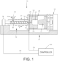
- FIG. 1 illustrates an exemplary injection molding apparatus 10 that generally includes an injection system 12 and a clamping system 14.
- a thermoplastic material may be introduced to the injection system 12 in the form of thermoplastic pellets 16.
- the thermoplastic pellets 16 may be placed into a hopper 18, which feeds the thermoplastic pellets 16 into a heated barrel 20 of the injection system 12.
- the thermoplastic pellets 16, after being fed into the heated barrel 20, may be driven to the end of the heated barrel 20 by a reciprocating screw 22.
- the heating of the heated barrel 20 and the compression of the thermoplastic pellets 16 by the reciprocating screw 22 causes the thermoplastic pellets 16 to melt, forming a molten thermoplastic material 24.
- the reciprocating screw 22 forces the molten thermoplastic material 24 toward a nozzle 26 to form a shot of thermoplastic material, which will be injected into a mold cavity 32 of a mold 28 via one or more gates 30, preferably three or less gates, that direct the flow of the molten thermoplastic material 24 to the mold cavity 32.
- the nozzle 26 may be separated from one or more gates 30 by a feed system (not shown).
- the mold cavity 32 is formed between a first mold side 25 and a second mold side 27 of the mold 28 and the first and second mold sides 25, 27 are held together under pressure by a press or clamping unit 34.
- the press or clamping unit 34 applies a clamping force during the molding process that is greater than the force exerted by the injection pressure acting to separate the two mold halves 25, 27, thereby holding the first and second mold sides 25, 27 together while the molten thermoplastic material 24 is injected into the mold cavity 32.
- the clamping system 14 may include a mold frame and a mold base.
- the molten thermoplastic material 24 takes the form of the mold cavity 32 as the material fills the mold cavity 32.
- the molten thermoplastic material 24 cools inside the mold cavity 32 until the thermoplastic material 24 solidifies.
- the press 34 releases the first and second mold sides 25, 27, the first and second mold sides 25, 27 are separated from one another, and the finished part may be ejected from the mold 28.
- the mold 28 may include a plurality of mold cavities 32 (e.g., eight, sixteen, 24, 48, 72 mold cavities) to increase overall production rates.
- a mold 28 having a plurality of mold cavities 32 may be referred to as a "multi-cavity mold.”
- the shapes of the cavities of the plurality of mold cavities 32 may be identical, similar or different from each other. (The latter may be considered a family of mold cavities 32).
- a controller 50 is communicatively connected with a sensor 52, located in the vicinity of the nozzle 26, and a screw control 36.
- the controller 50 may include a microprocessor, a memory having at least one database stored thereon, and one or more communication links.
- the sensor 52 may provide an indication of when the thermoplastic material is approaching the end of fill in the mold cavity 32.
- the sensor 52 may sense the presence of thermoplastic material optically, acoustically, pneumatically, mechanically, electro-mechanically, or by otherwise sensing pressure and/or temperature of the thermoplastic material.
- the controller 50 may be connected to the sensors 52 and screw control 36 via a wireless connection, a mechanical connection, a hydraulic connection, a pneumatic connection, or any other type of communication connection known to those having ordinary skill in the art that will allow the controller 50 to communicate with the sensors 52 and the screw control 36.
- the sensor 52 is a pressure sensor that measures (directly or indirectly) melt pressure of the molten thermoplastic material 24 in vicinity of the nozzle 26.
- the sensor 52 generates an electrical signal that is transmitted to the controller 50.
- the controller 50 then commands the screw control 36 to advance the screw 22 at a rate that maintains a desired melt pressure of the molten thermoplastic material 24 in the nozzle 26.
- the sensor 52 may directly measure the melt pressure, the sensor 52 may also indirectly measure the melt pressure by measuring other characteristics of the molten thermoplastic material 24, such as temperature, viscosity, flow rate, etc., which are indicative of melt pressure.
- the senor 52 could measure clamping force generated by the clamping system 14 at a mold parting line between the first and second mold parts 25, 27.
- the controller 50 may maintain the pressure according to the input from sensor 52.
- the sensor 52 could measure an electrical power demand by an electric press, which may be used to calculate an estimate of the pressure in the nozzle.
- the location of the flow front of the molten polymeric material can be detected at desired locations within the mold cavity 32.
- the fact that the flow front has reached a particular location in the mold cavity 32 may be detected by a sensor 52.
- the sensor 52 may take the form of a pressure transducer and may use vacuum pressure.
- One or more temperature sensors, such as thermal resistors, could be used instead of or in addition to a pressure sensor to determine or verify that the flow front has reached a given location of a mold cavity 32.
- Such a sensor 52 may operate by either sensing temperature or pressure, or by sensing a lack thereof.
- one or more cavities 32 in a multi-cavity mold 28 may become non-operational (e.g., blocked).
- the molten thermoplastic material 24 entering the multi-cavity mold 28 may cool quicker than expected and solidify before the entire cavity is filled with the molten thermoplastic material 24.
- the molten thermoplastic material 24 may cool and solidify in the gate of one of the cavities 32 or in an area within one of the cavities 32 proximate the gate, thereby blocking that cavity 32.
- some conventional multi-cavity molds 28 do not include a feedback mechanism that is disposed within the non-operational cavity 32 and indicates that the cavity 32 is non-operational.
- some conventional multi-cavity molds 28 do have such a feedback mechanism, in the form of a sensor disposed in each cavity 32 of the multi-cavity mold 28.
- disposing a sensor in each cavity 32 of the multi-cavity mold 28 is quite costly to install, maintain, and repair.
- the reciprocating screw 22 of the injection system 12 continues to inject the same amount of molten thermoplastic material 24 into each cavity 32 of the multi-cavity mold 28, even though one or more of these cavities 32 is non-operational. Consequently, the reciprocating screw 22 continues to advance toward the forward most position of the reciprocating screw 22 thereby injecting, or attempting to inject, the material into the remaining operational cavities 32. This can, in turn, lead to an excess amount of material being injected into one or more of the operational cavities 32, thereby resulting in flashing to one or more parts produced by the multi-cavity mold 28.
- the present disclosure aims to prevent this problem by detecting when one or more cavities 32 are non-operational without the use of sensors disposed in each of the cavities 32 or without the use of sensors disposed in any of the cavities 32 in the multi-cavity mold 28, and automatically adjusting a process parameter of the injection system 12 to compensate for the non-operational cavity, thereby maintaining the quality of the products and limiting downtime for repairs.
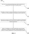
- FIG. 2 illustrates an example of a method 100 respectively, of detecting and compensating for one or more non-operational mold cavities in the injection molding apparatus 10.
- the method 100 generally includes the steps of: (1) injecting, via the reciprocating screw 32, the molten thermoplastic material into the mold cavities 32 (block 108), (2) measuring a first process parameter of the injection molding apparatus at a pre-determined time during or after the injecting (block 112), (3) based on the first process parameter, determining whether one or more mold cavities 32 are non-operational (block 116), and (4) when it is determined that one or more mold cavities are non-operational, automatically adjusting the first process parameter or a second process parameter of the injection molding apparatus 10 (block 120).
- the method 100 includes determining (e.g., calculating, recording), using the controller 50, or another computing device, one or more expected (or desired) process parameters at one or more pre-determined times during the injecting.
- the expected process parameters are generally determined based on the specifications of the part to be produced, such as, for example, the type of thermoplastic material from which the part is to be made, the overall dimensions of the product (e.g., height, width, length, radius, diameter, etc.), the amount of parts to be made (i.e., the amount of cavities in the multi-cavity mold), the specifications of the injection molding apparatus 10, one or more previous injection cycles performed using the injection molding apparatus 10 (or another injection molding apparatus) to produce quality molded parts, simulated injection cycles performed using a mold simulator, or combinations thereof.
- the controller 50 may determine the expected (or desired) melt pressure of the molten thermoplastic material 24 in the nozzle 26 during the injecting.
- the controller 50 may determine the expected (or desired) position of the reciprocating screw 22 prior to the beginning of the injecting and at another point in time during or after the injecting.
- the controller 50 may determine the expected cushion (i.e., the amount of molten thermoplastic material 24 that should be disposed between the check ring 60 and an end of the barrel 20 at the end of the injecting).
- the process parameter may also be an end-of-fill transition point, such as a screw position set point or a time set point.
- adjusting the process parameter can involve adjusting the end-of-fill transition point from a first pressure to a second pressure. The second pressure being lower than the first pressure.
- the injection molding apparatus 10 of the present disclosure may determine whether one or more cavities 32 in the plurality of cavities 28 are non-operational without the use of any sensors disposed in the cavities 32. More particularly, the controller 50 (or another computing device) determines whether one or more cavities 32 are non-operational based on the measured process parameters. In some cases, this determination may be based solely on the measured process parameters. As an example, this determination may be made by comparing one of the measured process parameters at several different points in time during the injecting, whereby a deviation in the values between the measured process parameters may be indicative of one or more cavities 32 being non-operational.
- the melt pressure of the molten thermoplastic material 24 should be steady or consistent throughout the injecting; thus, fluctuations in the melt pressure values at various pre-determined times during the injecting may indicate that at least one cavity 32 is non-operational.
- this determination may be based on a comparison between one or more expected parameters stored in the expected parameter database to one or more corresponding actual process parameters measured by the controller 50.
- the controller 50 compares the one or more expected parameters to the one or more corresponding actual parameters measured, and based on that comparison, determines whether there exists a difference, between the expected parameter(s) and the corresponding actual parameter(s). In some cases, a difference of any amount will indicate that one or more cavities 32 are non-operational.
- the controller 50 determines that one or more cavities 32 are non-operational.
- the difference between the two may be indicative of how many cavities 32 are non-operational.
- the controller 50 may compare the difference to a threshold difference; when the difference exceeds the threshold difference, the controller 50 determines that one or more cavities 32 are non-operational, whereas when the difference is less than the threshold difference, the controller 50 determines that all of the cavities 32 are operational.
- FIGS. 3A-4B illustrate examples of how the injection molding apparatus 10 described above can be used to determine whether one or more cavities 32 are non-operational and, in response to the detecting, to adjust a process parameter to compensate for at least one non-operational cavity.
- FIGS. 3A and 3B illustrate an actual position of the reciprocating screw 22 and an expected position of the reciprocating screw 22, respectively.
- FIGS. 4A and 4B illustrate an actual cushion 64 of the molten thermoplastic material 24 and an expected cushion 64 of the molten thermoplastic material 24, respectively.
- FIG. 3A illustrates an example actual parameter in the form of an actual position of the reciprocating screw 22 at a pre-determined time during the injecting.
- the reciprocating screw 22 is actually in the location illustrated in FIG. 3A at this pre-determined time during the injecting.
- the controller 50 compares the actual position of the reciprocating screw 22 to the expected position of the reciprocating screw 22 at the same pre-determined time during the injecting, which is illustrated in FIG. 3B .
- the expected position of the reciprocating screw 22 is different from the actual position of the reciprocating screw 22 illustrated in FIG. 3A .
- the actual position of the reciprocating screw 22 is further from the end of the barrel 20 than expected.
- the controller 50 may determine that one or more cavities 32 is non-operational and may respond by adjusting a process parameter of the plurality of process parameters to compensate for the non-operational cavity(ies).
- the controller 50 may use a machine learning algorithm to, based on the process parameter to be adjusted, adjust operation of the injection molding apparatus to compensate for the non-operational cavity(ies).
- FIG. 4A illustrates an example actual cushion 64 of the molten thermoplastic material 24, which is measured by the distance from a front end 62 of the reciprocating screw 22 to an end 68 of the barrel 22 of the injection molding apparatus 10, at a pre-determined time during the injecting.
- the cushion 64 of the molten thermoplastic material 24 is expected to have the particular length illustrated in FIG. 4B at this pre-determined time during the injecting.
- the controller 50 compares the actual cushion 64 of the molten thermoplastic material 24 to the expected cushion 64 of the molten thermoplastic material 24 during the injecting, which is illustrated in FIG. 4B . As evidenced by FIG.
- the injection molding apparatus 10 described herein can continue to perform the current injection molding cycle and subsequent injection molding cycles as part of the same injection molding run, all while continuing to make or yield production versions of the same injection molded part in the remaining operational cavities 32.
- thermoplastic injection molding process is described herein, the embodiments in this disclosure may also relate to other injection molding processes.
- Other injection molding processes include metal injection molding (“MIM”), reaction injection molding (“RIM”), liquid injection molding (“LIM”), structural foam molding, and liquid crystal polymer (“LCP”) molding.
Landscapes
- Engineering & Computer Science (AREA)
- Manufacturing & Machinery (AREA)
- Mechanical Engineering (AREA)
- Injection Moulding Of Plastics Or The Like (AREA)
Description
- The present disclosure generally relates to apparatuses and methods for injection molding and, more particularly, to apparatuses and methods for detecting and compensating for non-operational (e.g., blocked) cavities within a mold.
- Injection molding is a technology commonly used for high-volume manufacturing of parts made of thermoplastic material. During a repetitive injection molding process, a thermoplastic resin, most often in the form of small beads or pellets, is introduced to an injection molding apparatus that melts the resin beads under heat and pressure. The now-molten resin is forcefully injected into a mold cavity having a particular cavity shape. The injected plastic is held under pressure in the mold cavity, cooled, and then removed as a solidified part having a shape that essentially duplicates the cavity shape of the mold. The mold itself may have a single cavity or multiple cavities.
- An injection molding cycle, as used herein, or simply "cycle", can include the steps of (1) melting a shot of polymeric material; (2) clamping together two (or more) portions of a mold, such as a mold core and a mold cavity plate, that together form the mold walls that define one or more mold cavities (typically while the mold walls are in a cool condition relative to the temperature to which the molten thermoplastic material is heated prior to injection into the mold cavity); (3) injecting molten polymeric material into the one or more mold cavities; (4) packing or holding the material, i.e., applying one or more set pressures to the material, after the mold is full, to ensure adequate densification within the cavity and wait for material solidification in the gate(s) or runner(s) to prevent the material from flowing in the opposite direction through the gate(s) or runner(s); (5) waiting some period of time until the molded polymeric material cools to a temperature sufficient to eject the part, i.e. a temperature below its melt temperature, so that at least outside surfaces of the molded part are sufficiently solid so that the part will maintain its molded shape once ejected; (6) opening the portions of the mold that define the one or more mold cavities; (7) ejecting the molded part(s) from the one or more mold cavities; and (8) closing the two (or more) mold sections (for a subsequent cycle).
-
JPS57115835A -
US2016059461A1 discloses injection molding at substantially constant pressure with the use of rapid heating techniques, such as induction heating, at strategic locations within a mold to heat molding surfaces in a manner that mitigates problems typically associated with flow filling challenges. -
JPH0760807A - While the invention is defined in the independent claims, further aspects of the invention are set forth in the dependent claims, the drawings and the following description.
- The present disclosure describes a method of detecting at least one non-operational cavity in a multi-cavity mold during an injection molding cycle and automatically adjusting a process parameter of the injection molding cycle to compensate for the at least one non-operational cavity.
- The features of the present disclosure which are believed to be novel are set forth with particularity in the appended claims. The present disclosure may be best understood by reference to the following description taken in conjunction with the accompanying drawings, in which like reference numerals identify like elements in the several figures, in which:
-
FIG. 1 illustrates a schematic view of one example of an injection molding apparatus, constructed according to the teachings of the present disclosure; -
FIG. 2 is a flow chart depicting one example of a method of detecting and automatically adjusting for a non-operational cavity in a multi-cavity mold of the constant pressure injection molding apparatus ofFIG. 1 ; -
FIG. 3A is a cross-sectional view of a barrel of the injection molding apparatus ofFIG. 1 , showing an actual positon of the reciprocating screw of the injection molding apparatus; -
FIG. 3B is similar toFIG. 3A , but shows an expected position of the reciprocating screw; -
FIG. 4A is a cross-sectional view of a barrel of the injection molding apparatus ofFIG. 1 , showing the actual cushion; and -
FIG. 4B is similar toFIG. 4A , but shows the expected cushion. - Embodiments of the present invention generally relate to systems, machines, products, and methods of producing parts by injection molding and, more specifically, to systems, parts, and methods of detecting a non-operational cavity in a multi-cavity mold and automatically adjusting a process parameter to continue producing quality parts despite at least one cavity being non-operational.
- As used herein, the phrase "process parameter" generally refers to a parameter of an injection molding apparatus that is at least partially responsible for the quality of a part created using a multi-cavity mold of that injection molding apparatus. For example, the "process parameter" can include, but is not limited to, a nozzle pressure of an injection nozzle of the injection molding apparatus, a position of a reciprocating screw disposed in the injection molding apparatus, a cushion of the molten thermoplastic material, a melt pressure of a molten thermoplastic material being injected into the multi-cavity mold of the injection molding apparatus, an expected travel of the reciprocating screw, a shot size of the thermoplastic material, an end-of-fill transition point such as a screw position set point and a time set point, or any other parameter that could affect the operation of the injection molding apparatus during the cycle or the quality of the product.
- As used herein, the term "cavity percent fill" can refer to the percentage of the cavity that is filled on a volumetric basis, or the percentage of the cavity that is filled in relation to weight or mass of the molten material. For example, if a cavity is 95% filled, then the total volume of the mold cavity that is filled is 95% of the total volumetric capacity of the mold cavity. Alternatively, if a cavity is 95% filled, then the total weight of the material in the mold is equal to 95% of the weight specifications of a full part.
- As used herein, the term "cushion" refers to a distance from a front of a check ring to an end of a barrel at an end of the injection molding cycle. The cushion is generally based on both the mold volume and the target shot size. For a given mold with constant volume, when the target shot size is increased, the cushion will increase as well. Conversely, when the target shot size is decreased, the cushion will decrease as well.
- As used herein, the term "cycle time" is defined as a single iteration of an injection molding process that is required to fully form an injection molded part. Cycle time includes the collective time it takes to perform the steps of advancing molten thermoplastic material into a mold cavity, substantially filling the mold cavity with thermoplastic material, packing and/or holding pressure on the thermoplastic material within the cavity, cooling the thermoplastic material, separating first and second mold sides to expose the cooled thermoplastic material, removing the thermoplastic material, and closing the first and second mold sides.
- As used herein, the terms "filled" and "full," when used with respect to a mold cavity including thermoplastic material, are interchangeable and both terms mean that thermoplastic material has reached the maximum volumetric capacity of the mold cavity.
- As used herein, the phrase "flow front" refers to a leading edge of a shot of molten polymeric material, as experienced by the surfaces of the mold that define a mold cavity, as the molten polymeric material is progressing from a nozzle or gate of the mold cavity (i.e., a point or points of introduction of the molten polymeric material into the mold cavity) toward, and ultimately to, an end-of-fill location of the mold cavity.
- As used herein, the phrase "flow rate" generally refers to the volumetric flow rate of polymer as measured at the injection nozzle. This flow rate can be calculated based on the injection rate, the compressibility of the thermoplastic material, the pressure experienced by thermoplastic material as measured at the injection nozzle, and the cross sectional area of the nozzle, or measured with a suitable sensor located in the injection nozzle.
- As used herein, the phrase "melt temperature" generally refers to the temperature of the polymer that is maintained in the injection unit/barrel, and in the material feed system when a hot runner system is used, which keeps the polymer in a molten state. The melt temperature varies by material. However, a desired melt temperature is generally understood to fall within the ranges recommended by the material manufacturer.
- As used herein, the term "mold simulator" is defined as a software simulator such as AUTODESK® MOLDFLOW® ADVISER (TRADEMARK) by AUTODESK, INC., San Rafeal, California, used to simulate or model an injection molding cycle to determine a predicted or expected parameter of the injection molding apparatus during the subsequent actual injection molding cycle performed using the injection molding apparatus. The "mold simulator" may, for example, determine an expected position of the reciprocating screw or an expected location of a flow front of the molten thermoplastic material at fixed intervals of time. The "mold simulator" may also generate a pressure profile according to which an injection molding system might operate to achieve a selected flow front velocity profile. More specifically, the "mold simulator" may produce a model of a mold cavity with contour lines spaced along the length thereof, with the exact spacing depending on the selected profile. The contour lines may, for example, depict a flow front velocity throughout filling of the mold cavity that does not exceed a desired maximum or a flow front velocity that varies throughout filling of the mold cavity based on a custom flow front profile.
- As used herein, the term "production version" refers to an injection molded part that is a "quality molded part."
- As used herein, the term "quality molded part" refers to a molded part that satisfies one or more predetermined dimensional, performance, and/or aesthetic requirements within a defined tolerance range and is generally free of defects. Such dimensional requirements can include, but are not limited to, part lengths, widths, path lengths or perimeters, thickness, eccentricity, flatness or warp, parallelism, perpendicularity, and/or concentricity. Such performance requirements can include, but are not limited to, surviving and/or absorbing loads, such as tensile loads, compressive loads, torsional loads; exposure to vibration, surviving and/or absorbing electrical loads, and withstanding environmental exposures for a rated period of time. Additional performance requirements may include acoustic properties, such as, resonant frequencies, harmonics, and dampening behavior; and optical performance, such as percent transmission, dispersion, specularity, reflectance, and allowable aberrations. Aesthetic requirements can include, but are not limited to color, texture, surface texture, knit lines, blush, gap trap vestiges, markings, such as burn markings or freedom from undesired markings, and visible sink. Quality parts are also substantially free of defects, including, but not limited to lacking internal voids or containing only internal voids that do not compromise mechanical, electrical, or optical performance, substantially free of mold-in stress or have mold-in stress within a given tolerance, and substantially free of defects resulting from short shot or freeze-f during the molding process. Other requirements or part specification specified by a part customer are also within the contemplation of this definition. For example, the customer may require the molded part to have a given tensile and/or flexural moduli, impact resistance, hardness, chemical resistance and/or compatibility, abrasion resistance, thermal conductivity and/or resistivity, electrical conductivity and/or resistivity, reflectivity, specularity, clarity, percent transmission, index of refraction, and/or coefficient of friction.
- As used herein, the term "shot size" generally refers to the volume of polymer to be injected from the injection unit/barrel to completely fill the mold cavity or cavities. The shot size is determined based on the temperature and pressure of the polymer in the injection unit/barrel just prior to injection. In other words, the shot size is a total volume of molten plastic material that is injected in a stroke of an injection molding screw or ram at a given temperature and pressure. Shot size may include injecting molten plastic material into one or more injection cavities through one or more gates. The shot of molten plastic material may also be prepared and injected by one or more injection units/barrels.
- Referring to the figures in detail,
FIG. 1 illustrates an exemplaryinjection molding apparatus 10 that generally includes aninjection system 12 and a clamping system 14. A thermoplastic material may be introduced to theinjection system 12 in the form ofthermoplastic pellets 16. Thethermoplastic pellets 16 may be placed into ahopper 18, which feeds thethermoplastic pellets 16 into aheated barrel 20 of theinjection system 12. Thethermoplastic pellets 16, after being fed into theheated barrel 20, may be driven to the end of theheated barrel 20 by areciprocating screw 22. The heating of theheated barrel 20 and the compression of thethermoplastic pellets 16 by thereciprocating screw 22 causes thethermoplastic pellets 16 to melt, forming a molten thermoplastic material 24. - The
reciprocating screw 22 forces the molten thermoplastic material 24 toward anozzle 26 to form a shot of thermoplastic material, which will be injected into amold cavity 32 of amold 28 via one ormore gates 30, preferably three or less gates, that direct the flow of the molten thermoplastic material 24 to themold cavity 32. In other embodiments thenozzle 26 may be separated from one ormore gates 30 by a feed system (not shown). Themold cavity 32 is formed between afirst mold side 25 and asecond mold side 27 of themold 28 and the first and second mold sides 25, 27 are held together under pressure by a press or clampingunit 34. The press or clampingunit 34 applies a clamping force during the molding process that is greater than the force exerted by the injection pressure acting to separate the twomold halves mold cavity 32. To support these clamping forces, the clamping system 14 may include a mold frame and a mold base. - Once the shot of molten thermoplastic material 24 is injected into the
mold cavity 32, thereciprocating screw 22 stops traveling forward. The molten thermoplastic material 24 takes the form of themold cavity 32 as the material fills themold cavity 32. The molten thermoplastic material 24 cools inside themold cavity 32 until the thermoplastic material 24 solidifies. Once the thermoplastic material 24 has solidified, thepress 34 releases the first and second mold sides 25, 27, the first and second mold sides 25, 27 are separated from one another, and the finished part may be ejected from themold 28. Themold 28 may include a plurality of mold cavities 32 (e.g., eight, sixteen, 24, 48, 72 mold cavities) to increase overall production rates. For ease of reference, amold 28 having a plurality ofmold cavities 32 may be referred to as a "multi-cavity mold." The shapes of the cavities of the plurality ofmold cavities 32 may be identical, similar or different from each other. (The latter may be considered a family of mold cavities 32). - A
controller 50 is communicatively connected with a sensor 52, located in the vicinity of thenozzle 26, and ascrew control 36. Thecontroller 50 may include a microprocessor, a memory having at least one database stored thereon, and one or more communication links. The sensor 52 may provide an indication of when the thermoplastic material is approaching the end of fill in themold cavity 32. The sensor 52 may sense the presence of thermoplastic material optically, acoustically, pneumatically, mechanically, electro-mechanically, or by otherwise sensing pressure and/or temperature of the thermoplastic material. When pressure or temperature of the thermoplastic material is measured by the sensor 52, this sensor 52 may send a signal indicative of the pressure or the temperature to thecontroller 50 to provide a target pressure for thecontroller 50 to maintain in the mold cavity 32 (or in the nozzle 26) as the fill is completed. This signal may generally be used to control the molding process, such that variations in material viscosity, mold temperatures, melt temperatures, and other variations influencing filling rate, are adjusted by thecontroller 50. These adjustments may be made immediately during the molding cycle, or corrections can be made in subsequent cycles. Furthermore, several signals may be used in calculations over a number of cycles and then used by thecontroller 50 to calculate adjustments to the molding cycle. Thecontroller 50 may be connected to the sensor 52 and thescrew control 36 via wired connections 54, 56, respectively. In other embodiments, thecontroller 50 may be connected to the sensors 52 andscrew control 36 via a wireless connection, a mechanical connection, a hydraulic connection, a pneumatic connection, or any other type of communication connection known to those having ordinary skill in the art that will allow thecontroller 50 to communicate with the sensors 52 and thescrew control 36. - In the embodiment of
FIG. 1 , the sensor 52 is a pressure sensor that measures (directly or indirectly) melt pressure of the molten thermoplastic material 24 in vicinity of thenozzle 26. The sensor 52 generates an electrical signal that is transmitted to thecontroller 50. Thecontroller 50 then commands thescrew control 36 to advance thescrew 22 at a rate that maintains a desired melt pressure of the molten thermoplastic material 24 in thenozzle 26. While the sensor 52 may directly measure the melt pressure, the sensor 52 may also indirectly measure the melt pressure by measuring other characteristics of the molten thermoplastic material 24, such as temperature, viscosity, flow rate, etc., which are indicative of melt pressure. Likewise, the sensor 52 need not be located directly in thenozzle 26, but rather the sensor 52 may be located at any location within theinjection system 12 ormold 28 that is fluidly connected with thenozzle 26. As an example, the sensor 52 may be located in thebarrel 20 to measure the position of thereciprocating screw 22, the travel of thereciprocating screw 22, the cushion, or another process parameter. If the sensor 52 is not located within thenozzle 26, appropriate correction factors may be applied to the measured characteristic to calculate an estimate of the melt pressure in thenozzle 26. The sensor 52 need not be in direct contact with the injected fluid and may alternatively be in dynamic communication with the fluid and able to sense the pressure of the fluid and/or other fluid characteristics. In yet other embodiments, the sensor 52 need not be disposed at a location that is fluidly connected with the nozzle. Rather, the sensor 52 could measure clamping force generated by the clamping system 14 at a mold parting line between the first andsecond mold parts controller 50 may maintain the pressure according to the input from sensor 52. Alternatively, the sensor 52 could measure an electrical power demand by an electric press, which may be used to calculate an estimate of the pressure in the nozzle. - In an injection molding system, the location of the flow front of the molten polymeric material can be detected at desired locations within the
mold cavity 32. As described above, the fact that the flow front has reached a particular location in themold cavity 32 may be detected by a sensor 52. For instance, the sensor 52 may take the form of a pressure transducer and may use vacuum pressure. One or more temperature sensors, such as thermal resistors, could be used instead of or in addition to a pressure sensor to determine or verify that the flow front has reached a given location of amold cavity 32. Such a sensor 52 may operate by either sensing temperature or pressure, or by sensing a lack thereof. For instance, the sensor could sense a flow of air, and upon interruption, the sensor 52 may detect that interruption and communicate to thecontroller 50 that the air flow has been interrupted. Alternatively, or additionally, the location of the flow front may be determined based on time, screw position (e.g., monitored using a potentiometer), hydraulic pressure, the velocity of the flow front, or some other process characteristic. As an example, the location of the flow front can be determined by monitoring the screw position, which when analyzed over time, can be used to calculate the volume of thermoplastic material in the mold 28.As illustrated inFIG. 1 , the pressureinjection molding apparatus 10 further includes acheck ring 60 coupled (e.g., attached) to a portion of thereciprocating screw 22 within thebarrel 20. In the example illustrated inFIG. 1 , thecheck ring 60 is coupled to thereciprocating screw 22 at a position proximate to anend 62 of thereciprocating screw 22. Thecheck ring 60 is generally configured to prevent, or at least limit, a backflow of the molten thermoplastic material 24, i.e., the molten thermoplastic material 24 from flowing in a direction from thenozzle 26 toward thehopper 18. As an example, thecheck ring 60 may be configured to allow a backflow of to less than 10%, less than 9%, less than 8%, less than 7%, less than 6%, less than 5%, less than 4%, less than 3%, less than 2%, or less than 1% of the target shot size for the molten thermoplastic material 24. - During operation of the pressure
injection molding apparatus 10, it is possible that one ormore cavities 32 in amulti-cavity mold 28 may become non-operational (e.g., blocked). For example, the molten thermoplastic material 24 entering themulti-cavity mold 28 may cool quicker than expected and solidify before the entire cavity is filled with the molten thermoplastic material 24. As a result, the molten thermoplastic material 24 may cool and solidify in the gate of one of thecavities 32 or in an area within one of thecavities 32 proximate the gate, thereby blocking thatcavity 32. However, some conventionalmulti-cavity molds 28 do not include a feedback mechanism that is disposed within thenon-operational cavity 32 and indicates that thecavity 32 is non-operational. For this reason, some conventionalmulti-cavity molds 28 do have such a feedback mechanism, in the form of a sensor disposed in eachcavity 32 of themulti-cavity mold 28. However, disposing a sensor in eachcavity 32 of themulti-cavity mold 28 is quite costly to install, maintain, and repair. - In any event, when the
controller 50 of theinjection system 12 lacks any indication that one or more of thecavities 32 is non-operational, thereciprocating screw 22 of theinjection system 12 continues to inject the same amount of molten thermoplastic material 24 into eachcavity 32 of themulti-cavity mold 28, even though one or more of thesecavities 32 is non-operational. Consequently, thereciprocating screw 22 continues to advance toward the forward most position of thereciprocating screw 22 thereby injecting, or attempting to inject, the material into the remainingoperational cavities 32. This can, in turn, lead to an excess amount of material being injected into one or more of theoperational cavities 32, thereby resulting in flashing to one or more parts produced by themulti-cavity mold 28. The present disclosure aims to prevent this problem by detecting when one ormore cavities 32 are non-operational without the use of sensors disposed in each of thecavities 32 or without the use of sensors disposed in any of thecavities 32 in themulti-cavity mold 28, and automatically adjusting a process parameter of theinjection system 12 to compensate for the non-operational cavity, thereby maintaining the quality of the products and limiting downtime for repairs. -
FIG. 2 illustrates an example of amethod 100 respectively, of detecting and compensating for one or more non-operational mold cavities in theinjection molding apparatus 10. Themethod 100 generally includes the steps of: (1) injecting, via thereciprocating screw 32, the molten thermoplastic material into the mold cavities 32 (block 108), (2) measuring a first process parameter of the injection molding apparatus at a pre-determined time during or after the injecting (block 112), (3) based on the first process parameter, determining whether one ormore mold cavities 32 are non-operational (block 116), and (4) when it is determined that one or more mold cavities are non-operational, automatically adjusting the first process parameter or a second process parameter of the injection molding apparatus 10 (block 120). - In some examples, the
method 100 includes determining (e.g., calculating, recording), using thecontroller 50, or another computing device, one or more expected (or desired) process parameters at one or more pre-determined times during the injecting. The expected process parameters are generally determined based on the specifications of the part to be produced, such as, for example, the type of thermoplastic material from which the part is to be made, the overall dimensions of the product (e.g., height, width, length, radius, diameter, etc.), the amount of parts to be made (i.e., the amount of cavities in the multi-cavity mold), the specifications of theinjection molding apparatus 10, one or more previous injection cycles performed using the injection molding apparatus 10 (or another injection molding apparatus) to produce quality molded parts, simulated injection cycles performed using a mold simulator, or combinations thereof. For example, thecontroller 50 may determine the expected (or desired) melt pressure of the molten thermoplastic material 24 in thenozzle 26 during the injecting. As another example, thecontroller 50 may determine the expected (or desired) position of thereciprocating screw 22 prior to the beginning of the injecting and at another point in time during or after the injecting. As yet another example, thecontroller 50 may determine the expected cushion (i.e., the amount of molten thermoplastic material 24 that should be disposed between thecheck ring 60 and an end of thebarrel 20 at the end of the injecting). The process parameter may also be an end-of-fill transition point, such as a screw position set point or a time set point. For example, adjusting the process parameter can involve adjusting the end-of-fill transition point from a first pressure to a second pressure. The second pressure being lower than the first pressure. - Once the expected process parameters are determined, the expected process parameters may be stored in an expected parameters database stored in the memory of the controller 50 (or another computing device), to be later accessed by the
controller 50. In some cases, it may be beneficial to populate the expected parameters database with a plurality of different expected process parameters and/or a plurality of expected values for one or more process parameters. For example, the expected parameters database may be populated with a plurality of expected cushion values. Doing so may provide an operator, programmer, or thecontroller 50 with a range of acceptable or expected parameters for various process parameters. In some cases, thecontroller 50 may associate a timestamp with each expected parameter. - During the injecting, which may, for example, be performed based on substantially constant low pressure, the molten thermoplastic material 24 is injected into the
cavities 32, one or more of which may be non-operational. During or after the injecting, thecontroller 50 measures a plurality of process parameters of theinjection molding apparatus 10 at the one or more pre-determined times, which in some cases will correspond to the pre-determined times associated with the expected process parameters stored in the expected parameter database. Thecontroller 50 measures the plurality of process parameters using the sensor 52 and any other sensors employed in theinjection molding apparatus 10. Thecontroller 50 can, for example, measure the actual position of thereciprocating screw 22 at one or more pre-determined times during or after the injecting (e.g., at each timestamp that thecontroller 50 determined the expected position of the reciprocating screw 22). Thecontroller 50 can measure theactual cushion 64 of the molten thermoplastic material 24 at one or more pre-determined times during or after the injecting (e.g., at each timestamp that thecontroller 50 determined the expectedcushion 64 of the molten thermoplastic material 24). Thecontroller 50 can likewise measure the actual melt pressure of the molten thermoplastic material 24 toward thenozzle 26 at one or more pre-determined times during or after the injecting (e.g., at each timestamp that thecontroller 50 determined the expected melt pressure of the molten thermoplastic material 24. Finally, thecontroller 50 can measure the actual travel of thereciprocating screw 22 at one or more pre-determined times during or after the injecting (e.g., at each timestamp that thecontroller 50 determined the expected travel of the reciprocating screw 22). - Unlike conventional injection molding processes, which, as discussed above, may not include a feedback system or have a feedback system that is malfunctioning, the
injection molding apparatus 10 of the present disclosure may determine whether one ormore cavities 32 in the plurality ofcavities 28 are non-operational without the use of any sensors disposed in thecavities 32. More particularly, the controller 50 (or another computing device) determines whether one ormore cavities 32 are non-operational based on the measured process parameters. In some cases, this determination may be based solely on the measured process parameters. As an example, this determination may be made by comparing one of the measured process parameters at several different points in time during the injecting, whereby a deviation in the values between the measured process parameters may be indicative of one ormore cavities 32 being non-operational. As an example, during the injecting, the melt pressure of the molten thermoplastic material 24 should be steady or consistent throughout the injecting; thus, fluctuations in the melt pressure values at various pre-determined times during the injecting may indicate that at least onecavity 32 is non-operational. In other cases, this determination may be based on a comparison between one or more expected parameters stored in the expected parameter database to one or more corresponding actual process parameters measured by thecontroller 50. In particular, thecontroller 50 compares the one or more expected parameters to the one or more corresponding actual parameters measured, and based on that comparison, determines whether there exists a difference, between the expected parameter(s) and the corresponding actual parameter(s). In some cases, a difference of any amount will indicate that one ormore cavities 32 are non-operational. As an example, when theactual cushion 64 is greater than the expectedcushion 64, thecontroller 50 determines that one ormore cavities 32 are non-operational. Notably, when theactual cushion 64 is greater than the expectedcushion 64, the difference between the two may be indicative of howmany cavities 32 are non-operational. In other cases, thecontroller 50 may compare the difference to a threshold difference; when the difference exceeds the threshold difference, thecontroller 50 determines that one ormore cavities 32 are non-operational, whereas when the difference is less than the threshold difference, thecontroller 50 determines that all of thecavities 32 are operational. - When the
controller 50 determines that one or more of thecavities 32 are non-operational, the controller 50 (or another computing device) automatically adjusts one or more process parameters (e.g., the melt pressure of the molten thermoplastic material 24) of theinjection molding apparatus 10 to compensate for the non-operational cavity(ies) 32 without slowing down production or sacrificing quality of the molded part. Thecontroller 50 may, in some cases, automatically adjust the same parameter(s) used to determine that the one or more of thecavities 32 are non-operational in the first place. In other cases, however, thecontroller 50 may automatically adjust one or more different parameters than the parameters used to determine that the one or more of thecavities 32 are non-operational. -
FIGS. 3A-4B illustrate examples of how theinjection molding apparatus 10 described above can be used to determine whether one ormore cavities 32 are non-operational and, in response to the detecting, to adjust a process parameter to compensate for at least one non-operational cavity.FIGS. 3A and 3B illustrate an actual position of thereciprocating screw 22 and an expected position of thereciprocating screw 22, respectively.FIGS. 4A and 4B illustrate anactual cushion 64 of the molten thermoplastic material 24 and an expectedcushion 64 of the molten thermoplastic material 24, respectively. -
FIG. 3A illustrates an example actual parameter in the form of an actual position of thereciprocating screw 22 at a pre-determined time during the injecting. In other words, thereciprocating screw 22 is actually in the location illustrated inFIG. 3A at this pre-determined time during the injecting. In turn, thecontroller 50 compares the actual position of thereciprocating screw 22 to the expected position of thereciprocating screw 22 at the same pre-determined time during the injecting, which is illustrated inFIG. 3B . As evidenced byFIG. 3B , the expected position of thereciprocating screw 22 is different from the actual position of thereciprocating screw 22 illustrated inFIG. 3A . In fact, the actual position of thereciprocating screw 22 is further from the end of thebarrel 20 than expected. Accordingly, thecontroller 50 may determine that one ormore cavities 32 is non-operational and may respond by adjusting a process parameter of the plurality of process parameters to compensate for the non-operational cavity(ies). Thecontroller 50 may use a machine learning algorithm to, based on the process parameter to be adjusted, adjust operation of the injection molding apparatus to compensate for the non-operational cavity(ies). -
FIG. 4A illustrates an exampleactual cushion 64 of the molten thermoplastic material 24, which is measured by the distance from afront end 62 of thereciprocating screw 22 to anend 68 of thebarrel 22 of theinjection molding apparatus 10, at a pre-determined time during the injecting. Thecushion 64 of the molten thermoplastic material 24 is expected to have the particular length illustrated inFIG. 4B at this pre-determined time during the injecting. In turn, thecontroller 50 compares theactual cushion 64 of the molten thermoplastic material 24 to the expectedcushion 64 of the molten thermoplastic material 24 during the injecting, which is illustrated inFIG. 4B . As evidenced byFIG. 4A , theactual cushion 64 of the molten thermoplastic material 24 is different from the expectedcushion 64 of the molten thermoplastic material 24 illustrated inFIG. 4B . In fact, theactual cushion 64 of the molten thermoplastic material 24 is greater than expected. Accordingly, thecontroller 50 may determine that one ormore cavities 32 is non-operational and may respond by adjusting a process parameter of the plurality of process parameters to compensate for the non-operational cavity(ies). Thecontroller 50 may use a machine learning algorithm to, based on the process parameter to be adjusted, adjust operation of the injection molding apparatus to compensate for the non-operational cavity(ies). - It will be appreciated from the foregoing that in spite of the fact that at least one
cavity 32 of themulti-cavity mold 28 may be or become non-operational, theinjection molding apparatus 10 described herein can continue to perform the current injection molding cycle and subsequent injection molding cycles as part of the same injection molding run, all while continuing to make or yield production versions of the same injection molded part in the remainingoperational cavities 32. - Although a thermoplastic injection molding process is described herein, the embodiments in this disclosure may also relate to other injection molding processes. Other injection molding processes include metal injection molding ("MIM"), reaction injection molding ("RIM"), liquid injection molding ("LIM"), structural foam molding, and liquid crystal polymer ("LCP") molding.
Claims (13)
- A method of detecting and compensating for a non-operational mold cavity in an injection molding apparatus (10) having a plurality of mold cavities and an injection molding screw (22) or ram, the method comprising:injecting, via the injection molding screw (22) or ram, a molten thermoplastic material into the plurality of mold cavities (32);measuring a first process parameter of the injection molding apparatus (10) at a pre-determined time during or after the injecting;based on the first process parameter, determining whether one or more mold cavities of the plurality of mold cavities (32) are non-operational; andwhen it is determined that one or more mold cavities (32) are non-operational, automatically adjusting the first process parameter or a second process parameter of the injection molding apparatus (10);wherein measuring the first process parameter comprises measuring a nozzle pressure of an injection nozzle (26) of the injection molding apparatus (10) via a sensor disposed in the injection molding apparatus (10);characterized by comparing the measured nozzle pressure to an expected nozzle pressure corresponding to all of the plurality of mold cavities (32); andwhen a difference between the measured nozzle pressure and the expected nozzle pressure is greater than a predetermined threshold, generating a signal indicative of at least one mold cavity of the plurality of mold cavities (32) being non-operational.
- The method of claim 1, wherein the sensor is disposed proximate the injection nozzle;and/or wherein measuring the first process parameter comprises measuring a position of the injection molding screw or ram;preferably further comprising:comparing the measured position to an expected position corresponding to all of the plurality of mold cavities; andwhen a difference between the measured position and the expected position is greater than a predetermined threshold, generating a signal indicative of at least one mold cavity of the plurality of mold cavities being non-operational.
- The method of claim 1, wherein measuring the first process parameter comprises measuring a cushion of the molten thermoplastic material, measured from a front of the injection molding screw or ram to an end of a barrel of the injection molding apparatus;
preferably further comprising:comparing the measured cushion to an expected cushion corresponding to all of the plurality of mold cavities; andwhen a difference between the measured cushion and the expected cushion is greater than a predetermined threshold, generating a signal indicative of at least one mold cavity of the plurality of mold cavities being non-operational. - The method of any one of claims 1 to 3, wherein automatically adjusting the first parameter or the second parameter comprises adjusting a melt pressure of the molten thermoplastic material;
wherein automatically adjusting the melt pressure of the molten thermoplastic material preferably comprises decreasing the melt pressure of the molten thermoplastic material. - The method of any one of claims 1 to 4, wherein automatically adjusting the first parameter or the second parameter comprises adjusting an end-of-fill transition point from a first pressure to a second pressure, the second pressure being lower than the first pressure;
wherein automatically adjusting the end-of-fill transition point preferably comprises adjusting a screw position set point, a time set point, or other control method of which the end-of-fill transition point is dependent upon. - The method of claim 1, wherein determining whether the one or more mold cavities are non-operational comprises determining whether the one or more mold cavities are non-operational without using any cavity pressure sensors within the plurality of mold cavities;
or wherein after the adjusting, further comprising injecting, via the injection molding screw or ram, the molten thermoplastic material into the plurality of mold cavities at the adjusted process parameter. - A method of detecting and compensating for a non-operational mold cavity in an injection molding apparatus (10) having a plurality of mold cavities (32) and an injection molding screw (22) or ram, the method comprising:determining an expected parameter of the injection molding apparatus (10) at a pre-determined time during or after an injection molding cycle comprising injecting a molten thermoplastic material into the plurality of mold cavities (32);injecting, via the injection molding screw (22) or ram, the molten thermoplastic material into the plurality of mold cavities (32);determining an actual parameter of the injection molding apparatus at the pre-determined time during or after the injecting;based on determining the actual parameter, determining a parameter (10) differential between the expected parameter and the actual parameter;based on a parameter differential between the expected parameter and the actual parameter, determining whether one or more mold cavities of the plurality of mold cavities (32) are non-operational; andwhen it is determined that one or more mold cavities are non-operational, adjusting a process parameter of the injection molding apparatus (10) based at least in part on the parameter differential;wherein adjusting the process parameter of the injection molding apparatus comprises adjusting a melt pressure of the molten thermoplastic material;characterized in that adjusting the melt pressure of the molten thermoplastic material comprises decreasing the melt pressure of the molten thermoplastic material based at least in part on the parameter differential.
- The method of claim 7, wherein determining the expected parameter comprises: simulating, using a flow model simulator, the injecting prior to the injecting; and determining the expected parameter at the pre-determined time based on the simulated injection.
- The method of claim 7, wherein adjusting the process parameter of the injection molding apparatus comprises adjusting an end-of-fill transition point from a first pressure to a second pressure, the second pressure being lower than the first pressure;
wherein adjusting the end-of-fill transition point preferably comprises adjusting a screw position set point, a time set point, or other control method of which the end-of-fill transition point is dependent upon. - The method of claim 7, wherein determining the expected parameter comprises determining an expected nozzle pressure of an injection nozzle of the injection molding apparatus at the pre-determined time, and wherein determining the actual parameter comprises determining an actual nozzle pressure of the injection nozzle of the injection molding apparatus at the pre-determined time via a sensor disposed proximate the injection nozzle; orwherein determining the expected parameter comprises determining an expected position of the injection molding screw or ram of the injection molding apparatus, and wherein determining the actual parameter comprises determining an actual position of the injection molding screw or ram of the injection molding apparatus; orwherein determining the expected parameter comprises determining an expected cushion of the molten thermoplastic material at the pre-determined time, measured from a front of the injection molding screw or ram to an end of a barrel of the injection molding apparatus, and wherein determining the actual parameter comprises determining an actual cushion of the molten thermoplastic material at the pre-determined time; orwherein determining the expected parameter comprises determining an expected melt pressure at the pre-determined time, and wherein determining the actual parameter comprises determining an actual melt pressure at the pre-determined time via a sensor disposed proximate the injection molding screw or ram; orwherein determining whether the one or more mold cavities are non-operational comprises determining whether the one or more mold cavities are non-operational without using any cavity pressure sensors within the plurality of mold cavities; orfurther comprising comparing the expected parameter with the actual parameter, wherein determining whether the one or more mold cavities are non-operational is based on the comparing; orwherein after the adjusting, further comprising injecting, via the injection molding screw or ram, the molten thermoplastic material into the plurality of mold cavities at the adjusted process parameter.
- The method of claim 7, wherein the parameter of the injection molding apparatus is a position of the injection molding screw or ram.
- The method of claim 11, wherein adjusting the process parameter of the injection molding apparatus comprises adjusting a velocity of the injection molding screw or ram during the injecting.
- The method of claim 11, further comprising issuing an alert when it is determined that the one or more mold cavities are non-operational.
Applications Claiming Priority (2)
| Application Number | Priority Date | Filing Date | Title |
|---|---|---|---|
| US202063039356P | 2020-06-15 | 2020-06-15 | |
| PCT/US2021/033058 WO2021257228A1 (en) | 2020-06-15 | 2021-05-19 | Method of detecting and compensating for a non-operational mold cavity in an injection molding apparatus |
Publications (2)
| Publication Number | Publication Date |
|---|---|
| EP4164860A1 EP4164860A1 (en) | 2023-04-19 |
| EP4164860B1 true EP4164860B1 (en) | 2025-04-16 |
Family
ID=76375668
Family Applications (1)
| Application Number | Title | Priority Date | Filing Date |
|---|---|---|---|
| EP21731663.7A Active EP4164860B1 (en) | 2020-06-15 | 2021-05-19 | Method of detecting and compensating for a non-operational mold cavity in an injection molding apparatus |
Country Status (6)
| Country | Link |
|---|---|
| US (2) | US11718008B2 (en) |
| EP (1) | EP4164860B1 (en) |
| JP (1) | JP2023530123A (en) |
| CN (1) | CN115697667A (en) |
| CA (1) | CA3185997A1 (en) |
| WO (1) | WO2021257228A1 (en) |
Families Citing this family (2)
| Publication number | Priority date | Publication date | Assignee | Title |
|---|---|---|---|---|
| EP4164860B1 (en) | 2020-06-15 | 2025-04-16 | The Procter & Gamble Company | Method of detecting and compensating for a non-operational mold cavity in an injection molding apparatus |
| JP2024083700A (en) * | 2022-12-12 | 2024-06-24 | セイコーエプソン株式会社 | Molding management device, production plan generation device, and molding machine control device |
Family Cites Families (12)
| Publication number | Priority date | Publication date | Assignee | Title |
|---|---|---|---|---|
| JPS57115835A (en) * | 1981-01-10 | 1982-07-19 | Nec Corp | Packaging method for semiconductor device |
| JPS63307924A (en) * | 1987-06-10 | 1988-12-15 | Toshiba Mach Co Ltd | Sensing method for clogging of resin flow channel of injection molding machine |
| JPH0760807A (en) * | 1993-08-26 | 1995-03-07 | Sekisui Chem Co Ltd | Detection method for abnormal injection molding process |
| JPH0890622A (en) | 1994-09-28 | 1996-04-09 | Nec Tohoku Ltd | Injection molding device |
| JP2001219440A (en) * | 2000-02-09 | 2001-08-14 | Sony Disc Technology Inc | Multi-cavity molding apparatus and its molding method |
| TWI520836B (en) * | 2012-11-15 | 2016-02-11 | 寶鹼公司 | Method for substantially constant pressure injection molding of thin-walled parts |
| CA2919378C (en) * | 2013-08-01 | 2017-11-07 | Imflux, Inc. | Injection molding machines and methods for accounting for changes in material properties during injection molding runs |
| DE102014114874A1 (en) * | 2013-11-22 | 2015-05-28 | Christopherus Bader | Method for regulating the filling of at least one cavity |
| TW201609337A (en) | 2014-09-03 | 2016-03-16 | 艾弗洛斯公司 | Injection molding with localized heating in flow challenge regions |
| WO2017015573A1 (en) * | 2015-07-22 | 2017-01-26 | iMFLUX Inc. | Method of injection molding using one or more external sensors as a virtual cavity sensor |
| CN209478827U (en) * | 2018-12-19 | 2019-10-11 | 温州市环球汽车衬垫有限公司 | Mold Vent Clogged Recognition Structure |
| EP4164860B1 (en) | 2020-06-15 | 2025-04-16 | The Procter & Gamble Company | Method of detecting and compensating for a non-operational mold cavity in an injection molding apparatus |
-
2021
- 2021-05-19 EP EP21731663.7A patent/EP4164860B1/en active Active
- 2021-05-19 CN CN202180042948.1A patent/CN115697667A/en active Pending
- 2021-05-19 WO PCT/US2021/033058 patent/WO2021257228A1/en not_active Ceased
- 2021-05-19 JP JP2022577082A patent/JP2023530123A/en active Pending
- 2021-05-19 US US17/324,299 patent/US11718008B2/en active Active
- 2021-05-19 CA CA3185997A patent/CA3185997A1/en active Pending
-
2023
- 2023-06-20 US US18/211,953 patent/US12090697B2/en active Active
Also Published As
| Publication number | Publication date |
|---|---|
| CN115697667A (en) | 2023-02-03 |
| WO2021257228A1 (en) | 2021-12-23 |
| CA3185997A1 (en) | 2021-12-23 |
| US11718008B2 (en) | 2023-08-08 |
| US20230330906A1 (en) | 2023-10-19 |
| JP2023530123A (en) | 2023-07-13 |
| EP4164860A1 (en) | 2023-04-19 |
| US12090697B2 (en) | 2024-09-17 |
| US20210387393A1 (en) | 2021-12-16 |
Similar Documents
| Publication | Publication Date | Title |
|---|---|---|
| EP3849772B1 (en) | Methods for controlling injection molding processes based on actual plastic melt pressure or cavity pressure | |
| EP3325247B1 (en) | Method of injection molding using one or more external sensors as a virtual cavity sensor | |
| US20230031650A1 (en) | Systems and Approaches for Controlling an Injection Molding Machine | |
| US12090697B2 (en) | Method of injection molding with down cavity detection | |
| EP3846996B1 (en) | Closed loop control for injection molding processes | |
| EP3846997B1 (en) | Systems and approaches for controlling an injection molding machine | |
| US20170015029A1 (en) | Injection Molding with a Leaking Check Ring | |
| EP3317074B1 (en) | Sequential coining | |
| EP3619022B1 (en) | Method for controlling a rate or force of a clamp in a molding system using one or more strain gauges | |
| US20230041317A1 (en) | Systems and approaches for controlling an injection molding machine | |
| KR20100048392A (en) | Apparatus and method for injection molding | |
| JP2003112348A (en) | Method for injection molding | |
| EP4355547A1 (en) | Systems and approaches for manufacturing parts | |
| CA3186125A1 (en) | Independent startup mode for injection molding | |
| JPH09104050A (en) | Disk injection molding machine |
Legal Events
| Date | Code | Title | Description |
|---|---|---|---|
| STAA | Information on the status of an ep patent application or granted ep patent |
Free format text: STATUS: UNKNOWN |
|
| STAA | Information on the status of an ep patent application or granted ep patent |
Free format text: STATUS: THE INTERNATIONAL PUBLICATION HAS BEEN MADE |
|
| PUAI | Public reference made under article 153(3) epc to a published international application that has entered the european phase |
Free format text: ORIGINAL CODE: 0009012 |
|
| STAA | Information on the status of an ep patent application or granted ep patent |
Free format text: STATUS: REQUEST FOR EXAMINATION WAS MADE |
|
| 17P | Request for examination filed |
Effective date: 20230110 |
|
| AK | Designated contracting states |
Kind code of ref document: A1 Designated state(s): AL AT BE BG CH CY CZ DE DK EE ES FI FR GB GR HR HU IE IS IT LI LT LU LV MC MK MT NL NO PL PT RO RS SE SI SK SM TR |
|
| DAV | Request for validation of the european patent (deleted) | ||
| DAX | Request for extension of the european patent (deleted) | ||
| GRAP | Despatch of communication of intention to grant a patent |
Free format text: ORIGINAL CODE: EPIDOSNIGR1 |
|
| STAA | Information on the status of an ep patent application or granted ep patent |
Free format text: STATUS: GRANT OF PATENT IS INTENDED |
|
| INTG | Intention to grant announced |
Effective date: 20240813 |
|
| GRAS | Grant fee paid |
Free format text: ORIGINAL CODE: EPIDOSNIGR3 |
|
| RAP1 | Party data changed (applicant data changed or rights of an application transferred) |
Owner name: THE PROCTER & GAMBLE COMPANY |
|
| GRAA | (expected) grant |
Free format text: ORIGINAL CODE: 0009210 |
|
| STAA | Information on the status of an ep patent application or granted ep patent |
Free format text: STATUS: THE PATENT HAS BEEN GRANTED |
|
| AK | Designated contracting states |
Kind code of ref document: B1 Designated state(s): AL AT BE BG CH CY CZ DE DK EE ES FI FR GB GR HR HU IE IS IT LI LT LU LV MC MK MT NL NO PL PT RO RS SE SI SK SM TR |
|
| REG | Reference to a national code |
Ref country code: GB Ref legal event code: FG4D |
|
| REG | Reference to a national code |
Ref country code: CH Ref legal event code: EP |
|
| REG | Reference to a national code |
Ref country code: IE Ref legal event code: FG4D |
|
| REG | Reference to a national code |
Ref country code: DE Ref legal event code: R096 Ref document number: 602021029239 Country of ref document: DE |
|
| PGFP | Annual fee paid to national office [announced via postgrant information from national office to epo] |
Ref country code: DE Payment date: 20250507 Year of fee payment: 5 |
|
| PGFP | Annual fee paid to national office [announced via postgrant information from national office to epo] |
Ref country code: AT Payment date: 20250721 Year of fee payment: 5 |
|
| REG | Reference to a national code |
Ref country code: NL Ref legal event code: MP Effective date: 20250416 |
|
| PG25 | Lapsed in a contracting state [announced via postgrant information from national office to epo] |
Ref country code: NL Free format text: LAPSE BECAUSE OF FAILURE TO SUBMIT A TRANSLATION OF THE DESCRIPTION OR TO PAY THE FEE WITHIN THE PRESCRIBED TIME-LIMIT Effective date: 20250416 |
|
| REG | Reference to a national code |
Ref country code: AT Ref legal event code: MK05 Ref document number: 1785293 Country of ref document: AT Kind code of ref document: T Effective date: 20250416 |
|
| PG25 | Lapsed in a contracting state [announced via postgrant information from national office to epo] |
Ref country code: FI Free format text: LAPSE BECAUSE OF FAILURE TO SUBMIT A TRANSLATION OF THE DESCRIPTION OR TO PAY THE FEE WITHIN THE PRESCRIBED TIME-LIMIT Effective date: 20250416 Ref country code: ES Free format text: LAPSE BECAUSE OF FAILURE TO SUBMIT A TRANSLATION OF THE DESCRIPTION OR TO PAY THE FEE WITHIN THE PRESCRIBED TIME-LIMIT Effective date: 20250416 Ref country code: PT Free format text: LAPSE BECAUSE OF FAILURE TO SUBMIT A TRANSLATION OF THE DESCRIPTION OR TO PAY THE FEE WITHIN THE PRESCRIBED TIME-LIMIT Effective date: 20250818 |
|
| REG | Reference to a national code |
Ref country code: LT Ref legal event code: MG9D |
|
| PG25 | Lapsed in a contracting state [announced via postgrant information from national office to epo] |
Ref country code: GR Free format text: LAPSE BECAUSE OF FAILURE TO SUBMIT A TRANSLATION OF THE DESCRIPTION OR TO PAY THE FEE WITHIN THE PRESCRIBED TIME-LIMIT Effective date: 20250717 Ref country code: NO Free format text: LAPSE BECAUSE OF FAILURE TO SUBMIT A TRANSLATION OF THE DESCRIPTION OR TO PAY THE FEE WITHIN THE PRESCRIBED TIME-LIMIT Effective date: 20250716 |
|
| PG25 | Lapsed in a contracting state [announced via postgrant information from national office to epo] |
Ref country code: PL Free format text: LAPSE BECAUSE OF FAILURE TO SUBMIT A TRANSLATION OF THE DESCRIPTION OR TO PAY THE FEE WITHIN THE PRESCRIBED TIME-LIMIT Effective date: 20250416 |
|
| PG25 | Lapsed in a contracting state [announced via postgrant information from national office to epo] |
Ref country code: BG Free format text: LAPSE BECAUSE OF FAILURE TO SUBMIT A TRANSLATION OF THE DESCRIPTION OR TO PAY THE FEE WITHIN THE PRESCRIBED TIME-LIMIT Effective date: 20250416 |
|
| PG25 | Lapsed in a contracting state [announced via postgrant information from national office to epo] |
Ref country code: HR Free format text: LAPSE BECAUSE OF FAILURE TO SUBMIT A TRANSLATION OF THE DESCRIPTION OR TO PAY THE FEE WITHIN THE PRESCRIBED TIME-LIMIT Effective date: 20250416 |
|
| PG25 | Lapsed in a contracting state [announced via postgrant information from national office to epo] |
Ref country code: AT Free format text: LAPSE BECAUSE OF FAILURE TO SUBMIT A TRANSLATION OF THE DESCRIPTION OR TO PAY THE FEE WITHIN THE PRESCRIBED TIME-LIMIT Effective date: 20250416 |
|
| PG25 | Lapsed in a contracting state [announced via postgrant information from national office to epo] |
Ref country code: RS Free format text: LAPSE BECAUSE OF FAILURE TO SUBMIT A TRANSLATION OF THE DESCRIPTION OR TO PAY THE FEE WITHIN THE PRESCRIBED TIME-LIMIT Effective date: 20250716 |
|
| PG25 | Lapsed in a contracting state [announced via postgrant information from national office to epo] |
Ref country code: IS Free format text: LAPSE BECAUSE OF FAILURE TO SUBMIT A TRANSLATION OF THE DESCRIPTION OR TO PAY THE FEE WITHIN THE PRESCRIBED TIME-LIMIT Effective date: 20250816 |
|
| PG25 | Lapsed in a contracting state [announced via postgrant information from national office to epo] |
Ref country code: LV Free format text: LAPSE BECAUSE OF FAILURE TO SUBMIT A TRANSLATION OF THE DESCRIPTION OR TO PAY THE FEE WITHIN THE PRESCRIBED TIME-LIMIT Effective date: 20250416 |
|
| REG | Reference to a national code |
Ref country code: CH Ref legal event code: H13 Free format text: ST27 STATUS EVENT CODE: U-0-0-H10-H13 (AS PROVIDED BY THE NATIONAL OFFICE) Effective date: 20251223 |
|
| PG25 | Lapsed in a contracting state [announced via postgrant information from national office to epo] |
Ref country code: SM Free format text: LAPSE BECAUSE OF FAILURE TO SUBMIT A TRANSLATION OF THE DESCRIPTION OR TO PAY THE FEE WITHIN THE PRESCRIBED TIME-LIMIT Effective date: 20250416 Ref country code: DK Free format text: LAPSE BECAUSE OF FAILURE TO SUBMIT A TRANSLATION OF THE DESCRIPTION OR TO PAY THE FEE WITHIN THE PRESCRIBED TIME-LIMIT Effective date: 20250416 |
|
| PG25 | Lapsed in a contracting state [announced via postgrant information from national office to epo] |
Ref country code: LU Free format text: LAPSE BECAUSE OF NON-PAYMENT OF DUE FEES Effective date: 20250519 |
|
| PG25 | Lapsed in a contracting state [announced via postgrant information from national office to epo] |
Ref country code: CH Free format text: LAPSE BECAUSE OF NON-PAYMENT OF DUE FEES Effective date: 20250531 |
|
| REG | Reference to a national code |
Ref country code: DE Ref legal event code: R097 Ref document number: 602021029239 Country of ref document: DE |
|
| PG25 | Lapsed in a contracting state [announced via postgrant information from national office to epo] |
Ref country code: CZ Free format text: LAPSE BECAUSE OF FAILURE TO SUBMIT A TRANSLATION OF THE DESCRIPTION OR TO PAY THE FEE WITHIN THE PRESCRIBED TIME-LIMIT Effective date: 20250416 |
|
| PG25 | Lapsed in a contracting state [announced via postgrant information from national office to epo] |
Ref country code: EE Free format text: LAPSE BECAUSE OF FAILURE TO SUBMIT A TRANSLATION OF THE DESCRIPTION OR TO PAY THE FEE WITHIN THE PRESCRIBED TIME-LIMIT Effective date: 20250416 |
|
| PG25 | Lapsed in a contracting state [announced via postgrant information from national office to epo] |
Ref country code: SK Free format text: LAPSE BECAUSE OF FAILURE TO SUBMIT A TRANSLATION OF THE DESCRIPTION OR TO PAY THE FEE WITHIN THE PRESCRIBED TIME-LIMIT Effective date: 20250416 |
|
| PG25 | Lapsed in a contracting state [announced via postgrant information from national office to epo] |
Ref country code: IT Free format text: LAPSE BECAUSE OF FAILURE TO SUBMIT A TRANSLATION OF THE DESCRIPTION OR TO PAY THE FEE WITHIN THE PRESCRIBED TIME-LIMIT Effective date: 20250416 |
|
| REG | Reference to a national code |
Ref country code: BE Ref legal event code: MM Effective date: 20250531 |
|
| PG25 | Lapsed in a contracting state [announced via postgrant information from national office to epo] |
Ref country code: MC Free format text: LAPSE BECAUSE OF FAILURE TO SUBMIT A TRANSLATION OF THE DESCRIPTION OR TO PAY THE FEE WITHIN THE PRESCRIBED TIME-LIMIT Effective date: 20250416 |
|
| PG25 | Lapsed in a contracting state [announced via postgrant information from national office to epo] |
Ref country code: RO Free format text: LAPSE BECAUSE OF FAILURE TO SUBMIT A TRANSLATION OF THE DESCRIPTION OR TO PAY THE FEE WITHIN THE PRESCRIBED TIME-LIMIT Effective date: 20250416 |
|
| PLBE | No opposition filed within time limit |
Free format text: ORIGINAL CODE: 0009261 |
|
| STAA | Information on the status of an ep patent application or granted ep patent |
Free format text: STATUS: NO OPPOSITION FILED WITHIN TIME LIMIT |
|
| REG | Reference to a national code |
Ref country code: CH Ref legal event code: L10 Free format text: ST27 STATUS EVENT CODE: U-0-0-L10-L00 (AS PROVIDED BY THE NATIONAL OFFICE) Effective date: 20260225 |
|
| 26N | No opposition filed |
Effective date: 20260119 |
|
| GBPC | Gb: european patent ceased through non-payment of renewal fee |
Effective date: 20250716 |
|
| PG25 | Lapsed in a contracting state [announced via postgrant information from national office to epo] |
Ref country code: GB Free format text: LAPSE BECAUSE OF NON-PAYMENT OF DUE FEES Effective date: 20250716 |
|
| PG25 | Lapsed in a contracting state [announced via postgrant information from national office to epo] |
Ref country code: IE Free format text: LAPSE BECAUSE OF NON-PAYMENT OF DUE FEES Effective date: 20250519 |
|
| PG25 | Lapsed in a contracting state [announced via postgrant information from national office to epo] |
Ref country code: BE Free format text: LAPSE BECAUSE OF NON-PAYMENT OF DUE FEES Effective date: 20250531 |
|
| PG25 | Lapsed in a contracting state [announced via postgrant information from national office to epo] |
Ref country code: FR Free format text: LAPSE BECAUSE OF NON-PAYMENT OF DUE FEES Effective date: 20250616 |