EP4164251A2 - Hörhilfe - Google Patents
Hörhilfe Download PDFInfo
- Publication number
- EP4164251A2 EP4164251A2 EP23153285.4A EP23153285A EP4164251A2 EP 4164251 A2 EP4164251 A2 EP 4164251A2 EP 23153285 A EP23153285 A EP 23153285A EP 4164251 A2 EP4164251 A2 EP 4164251A2
- Authority
- EP
- European Patent Office
- Prior art keywords
- charger
- hearing aid
- housing
- transducer
- output
- Prior art date
- Legal status (The legal status is an assumption and is not a legal conclusion. Google has not performed a legal analysis and makes no representation as to the accuracy of the status listed.)
- Withdrawn
Links
Images


Classifications
-
- H—ELECTRICITY
- H04—ELECTRIC COMMUNICATION TECHNIQUE
- H04R—LOUDSPEAKERS, MICROPHONES, GRAMOPHONE PICK-UPS OR LIKE ACOUSTIC ELECTROMECHANICAL TRANSDUCERS; DEAF-AID SETS; PUBLIC ADDRESS SYSTEMS
- H04R25/00—Deaf-aid sets, i.e. electro-acoustic or electro-mechanical hearing aids; Electric tinnitus maskers providing an auditory perception
- H04R25/30—Monitoring or testing of hearing aids, e.g. functioning, settings, battery power
- H04R25/305—Self-monitoring or self-testing
-
- H—ELECTRICITY
- H04—ELECTRIC COMMUNICATION TECHNIQUE
- H04R—LOUDSPEAKERS, MICROPHONES, GRAMOPHONE PICK-UPS OR LIKE ACOUSTIC ELECTROMECHANICAL TRANSDUCERS; DEAF-AID SETS; PUBLIC ADDRESS SYSTEMS
- H04R2225/00—Details of deaf aids covered by H04R25/00, not provided for in any of its subgroups
- H04R2225/021—Behind the ear [BTE] hearing aids
- H04R2225/0216—BTE hearing aids having a receiver in the ear mould
-
- H—ELECTRICITY
- H04—ELECTRIC COMMUNICATION TECHNIQUE
- H04R—LOUDSPEAKERS, MICROPHONES, GRAMOPHONE PICK-UPS OR LIKE ACOUSTIC ELECTROMECHANICAL TRANSDUCERS; DEAF-AID SETS; PUBLIC ADDRESS SYSTEMS
- H04R2225/00—Details of deaf aids covered by H04R25/00, not provided for in any of its subgroups
- H04R2225/31—Aspects of the use of accumulators in hearing aids, e.g. rechargeable batteries or fuel cells
Definitions
- the present disclosure relates to hearing aids having speaker units. More particularly, the disclosure relates to different applications of hearing aids having speaker units, which speaker units have a housing configured to be positioned in the ear canal of a user. Even more particular, the present disclosure relates to hearing aids having speaker units with memory device, processor and/or sensors.
- the hearing aid most often comprises a housing configured to be positioned being the ear/pinna of the user, and a housing configured to be positioned in/at the ear canal of the user, most often termed an in-the-ear housing, and a member mechanically connecting the two.
- the member and the in-the-ear housing is often termed a speaker unit.
- the in-the-ear housing comprises a mold, such as a custom-shaped ear mold, this is sometimes termed a power mold as this often allow the use of a higher power output transducer due to a more closed sealing with the ear canal.
- the cornerstone to deliver the correct gain and output for the end-user.
- the speaker unit is calibrated to the hearing aid and fitting software so that for a certain mV output the receiver/output transducer delivers the correct sound pressure level to the user.
- Vent response and RECD in the speaker unit as the vent
- RECD is a coupled acoustics system with the receiver. This may be used to better calibrate the hearing aid fitting.
- the impedance of the receiver may be stored for future application implemented e.g. in software of the hearing aid processor.
- Speaker units may comprise multiple sensors, such as one or more of temperature, pressure, pulse/heart rate, etc. Each sensor will require calibration. The speaker unit could store this calibration data so the hearing aid and/or speaker unit may easily access them.
- a RITE hearing aid comprises (at least) two independent parts, an amplifier unit and a speaker Unit (SU).
- the HCP When the HCP is fitting the hearing aid, only the amplifier information can be detected by the Fitting system.
- the SU is not specifically known by the fitting system, only cursory information about it is typed in by the fitter. This information carries risk of entering wrong information, with associated risk that the sound in the hearing aid being too loud or too soft for the user.
- the SU typically needs replacement, which is sometimes done by the end user.
- the Amplifier unit may automatically adapt to the replacement SU, even if there are differences. It can also prevent the application of a SU that doesn't suit the end user, such as a too low sound pressure level as maximum output.
- Speaker Units have other features than emitting sound, eg. Sensor features or microphones, it is important to check compatibility between Amplifier unit and Speaker Unit.
- an RFID chip may be used for tracking hearing aids. This RFID chip may be readable when the hearing aid is lying on a table/surface, such as in a production line, hence the RFID chip needs to be placed somewhat parallel with the side of the hearing aid.
- the receiver/output transducer takes up a significant part of the instrument volume either behind the ear (in BTEs) or in the ear( such as Custom or RITE instruments).
- the maximum output a receiver can generate before it reaches an unacceptable distortion level is largely determined by the size.
- Distortion is when the output contains new frequency components which are correlated to the input signal (If uncorrelated it is "noise" not distortion). This aspect aims at delivering higher output without increasing the size or reducing the size while maintaining the output, or something in between. Let us call this size vs distortion limited output, Output/size ratio.
- a hearing aid may stop performing as intended due to e.g. earwax blocking filters in front of the receiver/output transducer or microphone/input transducer or the receiver being damaged due to drop.
- the end-user may not notice a decline in performance especially if the decline is a gradual degradation of performance. Caretakers cannot always assess if the instrument is performing correctly. In some cases, the end-user is simply not communicating to them that the hearing instrument is no longer working correctly or sufficiently.
- the present aspect provides a solution where the HI is to be charged using a cable, where one cable could be used for multiple devices.
- a similar concept is known from consumer electronics where three different variants, micro-USB, USB-C and lightning cables, is able to connect to many different products.
- Using a charge cable in a Hearing instrument has at least the following challenges.
- a memory unit may be included in a housing of the hearing instrument or in the detachable speaker unit. Data may be written and/or updated in the memory unit during use of the hearing instrument. This could enable diagnostic information to be retrieved and analyzed after failure. Further, aggregating or analyzing data from multiple failures of individual devices could yield information on other
- the electronic hardware may include micro-electronic-mechanical systems (MEMS), integrated circuits (e.g. application specific), microprocessors, microcontrollers, digital signal processors (DSPs), field programmable gate arrays (FPGAs), programmable logic devices (PLDs), gated logic, discrete hardware circuits, printed circuit boards (PCB) (e.g. flexible PCBs), and other suitable hardware configured to perform the various functionality described throughout this disclosure, e.g. sensors, e.g. for sensing and/or registering physical properties of the environment, the device, the user, etc.
- MEMS micro-electronic-mechanical systems
- integrated circuits e.g. application specific
- DSPs digital signal processors
- FPGAs field programmable gate arrays
- PLDs programmable logic devices
- gated logic discrete hardware circuits
- PCB printed circuit boards
- PCB printed circuit boards
- Computer program shall be construed broadly to mean instructions, instruction sets, code, code segments, program code, programs, subprograms, software modules, applications, software applications, software packages, routines, subroutines, objects, executables, threads of execution, procedures, functions, etc., whether referred to as software, firmware, middleware, microcode, hardware description language, or otherwise.
- a hearing device may be or include a hearing aid that is adapted to improve or augment the hearing capability of a user by receiving an acoustic signal from a user's surroundings, generating a corresponding audio signal, possibly modifying the audio signal and providing the possibly modified audio signal as an audible signal to at least one of the user's ears. 'Improving or augmenting the hearing capability of a user' may include compensating for an individual user's specific hearing loss.
- the "hearing device” may further refer to a device such as a hearable, an earphone or a headset adapted to receive an audio signal electronically, possibly modifying the audio signal and providing the possibly modified audio signals as an audible signal to at least one of the user's ears.
- Such audible signals may be provided in the form of an acoustic signal radiated into the user's outer ear, or an acoustic signal transferred as mechanical vibrations to the user's inner ears through bone structure of the user's head and/or through parts of the middle ear of the user.
- the hearing device is adapted to be worn in any known way. This may include i) arranging a unit of the hearing device behind the ear with a tube leading air-borne acoustic signals into the ear canal or with a receiver/ loudspeaker arranged close to or in the ear canal and connected by conductive wires (or wirelessly) to the unit behind the ear, such as in a Behind-the-Ear type hearing aid, and/ or ii) arranging the hearing device entirely or partly in the pinna and/ or in the ear canal of the user such as in an In-the-Ear type hearing aid or In-the-Canal/ Completely-in-Canal type hearing aid, or iii) arranging a unit of the hearing device attached to a fixture implanted into the skull bone such as in a Bone Anchored Hearing Aid, or iv) arranging a unit of the hearing device as an entirely or partly implanted unit such as in a Bone Anchored Hearing Aid.
- the hearing device may be implemented
- a “hearing system” refers to a system comprising one or two hearing devices
- a “binaural hearing system” refers to a system comprising two hearing devices where the devices are adapted to cooperatively provide audible signals to both of the user's ears.
- the hearing system or binaural hearing system may further include one or more auxiliary device(s) that communicates with at least one hearing device, the auxiliary device affecting the operation of the hearing devices and/or benefitting from the functioning of the hearing devices.
- a wired or wireless communication link between the at least one hearing device and the auxiliary device is established that allows for exchanging information (e.g. control and status signals, possibly audio signals) between the at least one hearing device and the auxiliary device.
- Such auxiliary devices may include at least one of a remote control, a remote microphone, an audio gateway device, a wireless communication device, e.g. a mobile phone (such as a smartphone) or a tablet or another device, e.g. comprising a graphical interface, a public-address system, a car audio system or a music player, or a combination thereof.
- the audio gateway may be adapted to receive a multitude of audio signals such as from an entertainment device like a TV or a music player, a telephone apparatus like a mobile telephone or a computer, e.g. a PC.
- the auxiliary device may further be adapted to (e.g.
- the remote control is adapted to control functionality and/or operation of the at least one hearing device.
- the function of the remote control may be implemented in a smartphone or other (e.g. portable) electronic device, the smartphone / electronic device possibly running an application (APP) that controls functionality of the at least one hearing device.
- APP application
- a hearing device in general, includes i) an input unit such as a microphone for receiving an acoustic signal from a user's surroundings and providing a corresponding input audio signal, and/or ii) a receiving unit for electronically receiving an input audio signal.
- the hearing device further includes a signal processing unit for processing the input audio signal and an output unit for providing an audible signal to the user in dependence on the processed audio signal.
- the input unit may include multiple input microphones, e.g. for providing direction-dependent audio signal processing.
- Such directional microphone system is adapted to (relatively) enhance a target acoustic source among a multitude of acoustic sources in the user's environment and/or to attenuate other sources (e.g. noise).
- the directional system is adapted to detect (such as adaptively detect) from which direction a particular part of the microphone signal originates. This may be achieved by using conventionally known methods.
- the signal processing unit may include an amplifier that is adapted to apply a frequency dependent gain to the input audio signal.
- the signal processing unit may further be adapted to provide other relevant functionality such as compression, noise reduction, etc.
- the output unit may include an output transducer such as a loudspeaker/ receiver for providing an air-borne acoustic signal transcutaneously or percutaneously to the skull bone or a vibrator for providing a structure-borne or liquid-borne acoustic signal.
- an output transducer such as a loudspeaker/ receiver for providing an air-borne acoustic signal transcutaneously or percutaneously to the skull bone or a vibrator for providing a structure-borne or liquid-borne acoustic signal.
- Fig. 1 schematically illustrates a hearing device HD comprising a behind-the-ear housing, BTE, which is configured to be positioned in the area between the pinna and the skull of a user.
- BTE behind-the-ear housing
- the BTE comprises the majority of electronic components of the hearing device, such as microphone system comprising first and second microphones, FM and RM, processor SPU, memory MEM, power source BAT, wireless interface(es) I and II, however, one or more of these components may be located in or distributed across other parts, such as an In-The-Ear housing/part ITE.
- the ITE part comprises an output transducer SP, which is configured to transform a processed electrical signal into a signal that the user may perceive as sound, such as air born audio.
- One or more of the electronic components may be arranged in connection with or on a substrate SUB.
- the power source BAT may be a primary or secondary battery, i.e. replaceable or rechargeable. The recharging may be contact charging or wireless charging.
- the wireless interface may include an inductively-based system comprising a coil configured for reception and/or transmission of low frequency signals, such as magnetic induction signals, e.g. to/from a hearing device located contralaterally.
- an inductively-based system comprising a coil configured for reception and/or transmission of low frequency signals, such as magnetic induction signals, e.g. to/from a hearing device located contralaterally.
- the wireless interface may include an RF-frequency based system, comprising a radio frequency antenna, e.g., an antenna configured for reception and/or transmission at around 2.4 GHz.
- a radio frequency antenna e.g., an antenna configured for reception and/or transmission at around 2.4 GHz.
- the speaker unit could include one or more sensors, such as temperature sensor, accelerometer, vibration sensor,
- a hearing instrument When a hearing instrument is provided with a writable memory, such as an NVRAM, EEPROM or the like, the hearing instrument will be able to store/modify/update information in that memory. If the memory device is positioned/arranged in a detachable speaker unit, an analysis of this data is also possible without the hearing instrument acting as an interface to the data.
- the data may be read out via a connector in the detachable speaker unit or may be wirelessly accessible. The wireless accessibility may also be used by the hearing aid.
- Such data could be read out via a processor in the hearing instrument and, e.g., subsequently transmitted to an external device, such as a computer, tablet, smartphone or the like, via a communication interface in the hearing instrument, such as a wired or wireless interface.
- the data could be processed in some manner in the hearing aid and/or in the external device.
- the communication interface could be communicating via an intermediate device, such as a charger, such as a portable charger or table charger.
- the charger could be a charger using wireless charging or a charger using contact charging.
- the intermediate device could then also have a charger communications interface, which may be wired or wirelessly communicating with a computer, tablet or smart phone, or to a cloud-based service, such as via the Internet.
- One example of data stored in the memory which could be stored in the detachable speaker unit, such as a speaker unit with an earmold, is a date of when the speaker was first used, that is, used by the user for the first time. This could make it possible to
- Another example could be storing information on extreme environmental conditions i.e. drop/accelerations, temperature, humidity etc. This would make it possible to
- Another example could be storing information on the settings used for the speaker unit. This would make it possible to
- such data may be aggregated from several speaker units so as to determine if problems to a specific speaker unit is a general problem or a user specific problem.
- this data could include information as listed in the following.
- a warning signal may be provided to the user if for some reasons a parameter is out of it's normal range. This could include warning the user that a speaker unit with a wrong maximum output sound pressure level is attached. A wrong SPL could lead to a distorted or potentially damaging signal being provided to the user.
- the parameter may be determined during production, and the parameter values stored in the specific speaker unit, where the hearing aid is then able to adapt the processed signal to specific characteristics of the specific speaker unit attached to the hearing aid.
- a speaker unit may need to be replaced, either by the user or at a hearing health care professional (HCP).
- HCP hearing health care professional
- a hearing aid supports remote fitting, i.e. fitting or adaptation of parameters at a location remote from a hearing care professional.
- remote fitting situation when no hearing health care professional is present to warrant patient safety, optimum fitting it is even more important that an automatic check ensures that the correct speaker unit is applied to the correct amplifier.
- a wrong fitting could result in undesirable fitting with HI being located uncomfortably and in worst case situations result in too loud or too low sound level.
- the need for automatic detection is even more evident for end-users who are visual impaired.
- the present disclosure thus provides a hearing aid having a processor configured to detect identity of a speaker unit being attached to a hearing aid housing, and checking said identity of the speaker unit.
- the identity may be transmitted to a remote unit, such as a fitting device or computer. If said identity check results in a speaker unit not being identified as an allowed device, the hearing aid may be configured to provide an alarm signal.
- an RFID chip could be used for tracking a hearing instrument. This could be useful in automated production facilities where an instrument may pass through different production stations or at the end of production and the instrument needs to be packages and a final check of the instrument type or identity could be verified automatically or at least read out so an operator may verify prior to packaging.
- This RFID chip should be readable when the hearing instrument is lying on a table, hence the RFID chip needs to be placed somewhat parallel with the side of the hearing aid.
- the RFID has been placed horizontally on a flap on the PCB.
- the flap with the RFID chip has then been bended down the side of the rack in the assembly process.
- the present disclosure thus provides a hearing aid having a housing having first and second sides and interconnecting top and bottom parts connecting the first and second sides so as to establish at least part of a housing.
- an RFID chip is arranged so as to be parallel with at least one of the first or second sides.
- the idea is switching between in which ear the sensor, such as PPG, EEG or IMU, is active based on e.g.
- Acoustical self-test of a hearing aid may be done by the hearing aid playing a test signal through the receiver and the signal being picked up by the microphone subsequently being analyzed. If the received signal differs significantly from the reference signal emitted the HI performance is assumed degraded and the user may be warned. Unfortunately, when performing a self-test, the audio signals are easily disturbed/polluted by noise in the surroundings. Also, it is not always possible to detect/determine if the degradation is in the microphone or receiver path.
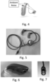
- Fig. 4 illustrates ambient noise being mixed with sound from the output transducer at the microphone system of the hearing aid.
- the present disclosure proposes to do a self-test when the HI is placed in a charger or similar box with a lid. When the lid is closed the ambient noise is reduced or even eliminated and the results become more reliable.
- the self-test can be initiated automatically for instance when the charging is completed or at a certain level or even when charging is initiated.
- the result of the self-test may be conveyed to the user via displayed on a mobile phone in wireless communication with the hearing aid or the charger device, or visually by means of e.g. LEDs on either hearing aid or charger.
- the self-test When the self-test is triggered by the charging device it may be safe to assume that the hearing aid is not placed on or in the ear of the user, and consequently it will be possible to test with full audio output without risk of injury to the user/wearer.
- Manually starting the test could also be an option, e.g. from an app on a smartphone or from a software running on a computer in communication with the hearing aid.
- enclosure e.g. a coffee mug could be used as enclosure.
- a charger box may be provided with a speaker and/or microphone in the inner space created in the charger when the lid is closed. Assuming these would be less exposed to the surroundings, it may be assumed that they are generally more reliable than those of the hearing aid and they thus will provide more accurate signals. Especially if combined with the microphones and speakers in the HI. As above, testing may be initiated at any point in the charging process, or after the charging process has been concluded.
- testing may be performed in pairs, advantageously in a charger with a closeable lid.
- Another way of increasing the accuracy of the self-test, possibly without adding additional components in the charger, is letting the hearing aids in a binaural set (Left and Right) test each other.
- a test signal may thus be emitted by one, or both, hearing aids, and the sound then be picked up by one or both of the hearing aids.
- the received audio signal may be compared to the reference (outputted) signal or the two received signals may be compared in some manner.
- One assumption during the test could be that in the charger box, the output transducer of one hearing aid is closer to the input transducer of the other hearing aid.
- speaker and microphone is included in the charger it would be possible to make a self-test of the charger box elements by rendering a test signal via the speaker which is then received by the microphone. By analyzing the signal, it can be detected if the microphone and speaker of the charger box are functioning as intended.
- One test could be that a speaker in the charger renders sound that is then picked up by the microphone system of one or more hearing aids in the charger.
- One test could be that the speaker of one hearing aid in the charger renders sound that is then picked up by the microphone system of the charger.
- One test could be that the speaker of one hearing aid renders sound that is then picked up by the microphone system of another hearing aid in the charger.
- Processing of the test signals may be performed by one or more of the hearing aids, a processor in the charger, a processor in an external device in wireless or wired communication with the charger and/or hearing aid(s).
- Self-test of the HI can reduce the risk of end-users not getting the help they need from the HI. Potentially warranty cost can be reduced because blocked filters are detected early.
- Fig. 5 illustrates an alternative charger device of a set of hearing aids.
- the basic idea is a cable charger which is able to charge 2 instruments simultaneously.
- a “base” which serves different purposes including providing stability and housing electronics.
- the base could include a weight element to provide extra stability.
- a power converter may be included in the base.
- the base may be connected at one end via a USB connector to a power supply.
- Alternative interfaces may of cause be provided.
- the hearing aids are charged via a physical interface which could be reused across different hearing aid styles to enable using one charger for different type and styles of hearing aids.
- This does not only reduce the number of different chargers but also enables using one charger even if the use is using different hearing aids at the left and right ear, such as a so-called BTE at one ear and a custom or RITE device at the other ear.
- a "Base" with significant weight(compared to the cable) and a non-slip bottom surface is placed at the fork. This could also include or be supplemented by a magnetic device.
- Some of the electronics needed for charging the battery in the hearing aid could be placed in the "base”. This could potentially save space in the hearing aid and reduce heating of the hearing aid during charging. Heating of a hearing aid is critical since it is a medical device which get in contact with the skin. Even if the hearing aid is not worn while changing it can be taken directly from the charger and placed on the ear/skin. Also, an increased heat may damage or reduce lifetime of the battery.
- a rotational symmetric connector system is preferred, see Figs. 6 and 7 . If possible the plugs should be guided towards each other using a combination of magnets and/or metal pieces, such as rings. With magnets there is however a risk of damaging the receiver/speaker so this will need to be considered in the design.
- the hearing aid is able to function while being charged, it may also be possible to charge the hearing aid via a Powerbank, a charging case, from a laptop, wallcharger etc. while on the move and wearing the hearing aids, see Figure 8 .
- the base could feature a clip which could be attached to e.g. a shirt to relieve the stress in the charging connector.
- Another option would be not having the "Base" at the Y of the cable and place the electronics in either the Hearing Aid or by the USB-plug since this will reduce the need for a "clip".
Priority Applications (1)
| Application Number | Priority Date | Filing Date | Title |
|---|---|---|---|
| EP23153285.4A EP4164251A2 (de) | 2023-01-25 | 2023-01-25 | Hörhilfe |
Applications Claiming Priority (1)
| Application Number | Priority Date | Filing Date | Title |
|---|---|---|---|
| EP23153285.4A EP4164251A2 (de) | 2023-01-25 | 2023-01-25 | Hörhilfe |
Publications (1)
| Publication Number | Publication Date |
|---|---|
| EP4164251A2 true EP4164251A2 (de) | 2023-04-12 |
Family
ID=85076476
Family Applications (1)
| Application Number | Title | Priority Date | Filing Date |
|---|---|---|---|
| EP23153285.4A Withdrawn EP4164251A2 (de) | 2023-01-25 | 2023-01-25 | Hörhilfe |
Country Status (1)
| Country | Link |
|---|---|
| EP (1) | EP4164251A2 (de) |
-
2023
- 2023-01-25 EP EP23153285.4A patent/EP4164251A2/de not_active Withdrawn
Similar Documents
| Publication | Publication Date | Title |
|---|---|---|
| US20160360328A1 (en) | Hearing aid configuration detection | |
| CN106341768B (zh) | 具有可分离扬声器单元的听力装置 | |
| EP3675524A1 (de) | Verfahren zur bestimmung eines zustands eines pfads von akustischem feedback eines am kopf tragbaren hörgeräts sowie am kopf tragbares hörgerät | |
| CN111669691B (zh) | 包括传感器配置检测器的听力装置 | |
| US11477585B2 (en) | Speaker unit for a hearing aid device system, and hearing aid device system | |
| US20210204077A1 (en) | Hearing device including an external antenna and an internal parasitic element | |
| US20220377473A1 (en) | Method for charging at least one hearing device and a hearing aid system | |
| CN111050260A (zh) | 降噪方法及系统 | |
| US11818550B2 (en) | Hearing instruments with receiver posterior to battery | |
| US20220322019A1 (en) | Method and system of fitting a hearing device | |
| EP3435689A1 (de) | Einstellung eines hörgeräts mit hörgeräteeigenschaftsidentifizierung | |
| EP4164251A2 (de) | Hörhilfe | |
| US20220046369A1 (en) | Hearing aid and a method for enhancing and/or protecting a user's hearing ability | |
| EP3113512A1 (de) | Kopplungsvorrichtung | |
| US20230209238A1 (en) | Charger device for hearing devices | |
| US11785398B2 (en) | Hearing aid with transmission power adaptation | |
| US11665489B2 (en) | Hearing aid with speaker unit assembly | |
| CN116032028A (zh) | 用于听力装置的充电装置 | |
| CN116939460A (zh) | 用于cros听力设备系统的cros单元 |
Legal Events
| Date | Code | Title | Description |
|---|---|---|---|
| PUAI | Public reference made under article 153(3) epc to a published international application that has entered the european phase |
Free format text: ORIGINAL CODE: 0009012 |
|
| STAA | Information on the status of an ep patent application or granted ep patent |
Free format text: STATUS: THE APPLICATION HAS BEEN PUBLISHED |
|
| AK | Designated contracting states |
Kind code of ref document: A2 Designated state(s): AL AT BE BG CH CY CZ DE DK EE ES FI FR GB GR HR HU IE IS IT LI LT LU LV MC ME MK MT NL NO PL PT RO RS SE SI SK SM TR |
|
| STAA | Information on the status of an ep patent application or granted ep patent |
Free format text: STATUS: THE APPLICATION HAS BEEN WITHDRAWN |
|
| RIC1 | Information provided on ipc code assigned before grant |
Ipc: H04R 25/00 20060101AFI20230614BHEP |
|
| 18W | Application withdrawn |
Effective date: 20230619 |