EP4164101A1 - Dc-to-dc converter assembly - Google Patents
Dc-to-dc converter assembly Download PDFInfo
- Publication number
- EP4164101A1 EP4164101A1 EP21201413.8A EP21201413A EP4164101A1 EP 4164101 A1 EP4164101 A1 EP 4164101A1 EP 21201413 A EP21201413 A EP 21201413A EP 4164101 A1 EP4164101 A1 EP 4164101A1
- Authority
- EP
- European Patent Office
- Prior art keywords
- choke coil
- coil system
- converter
- converter assembly
- assembly according
- Prior art date
- Legal status (The legal status is an assumption and is not a legal conclusion. Google has not performed a legal analysis and makes no representation as to the accuracy of the status listed.)
- Withdrawn
Links
Images

Classifications
-
- H—ELECTRICITY
- H02—GENERATION; CONVERSION OR DISTRIBUTION OF ELECTRIC POWER
- H02M—APPARATUS FOR CONVERSION BETWEEN AC AND AC, BETWEEN AC AND DC, OR BETWEEN DC AND DC, AND FOR USE WITH MAINS OR SIMILAR POWER SUPPLY SYSTEMS; CONVERSION OF DC OR AC INPUT POWER INTO SURGE OUTPUT POWER; CONTROL OR REGULATION THEREOF
- H02M1/00—Details of apparatus for conversion
- H02M1/32—Means for protecting converters other than automatic disconnection
-
- H—ELECTRICITY
- H02—GENERATION; CONVERSION OR DISTRIBUTION OF ELECTRIC POWER
- H02M—APPARATUS FOR CONVERSION BETWEEN AC AND AC, BETWEEN AC AND DC, OR BETWEEN DC AND DC, AND FOR USE WITH MAINS OR SIMILAR POWER SUPPLY SYSTEMS; CONVERSION OF DC OR AC INPUT POWER INTO SURGE OUTPUT POWER; CONTROL OR REGULATION THEREOF
- H02M1/00—Details of apparatus for conversion
- H02M1/40—Means for preventing magnetic saturation
-
- H—ELECTRICITY
- H02—GENERATION; CONVERSION OR DISTRIBUTION OF ELECTRIC POWER
- H02M—APPARATUS FOR CONVERSION BETWEEN AC AND AC, BETWEEN AC AND DC, OR BETWEEN DC AND DC, AND FOR USE WITH MAINS OR SIMILAR POWER SUPPLY SYSTEMS; CONVERSION OF DC OR AC INPUT POWER INTO SURGE OUTPUT POWER; CONTROL OR REGULATION THEREOF
- H02M3/00—Conversion of DC power input into DC power output
- H02M3/02—Conversion of DC power input into DC power output without intermediate conversion into AC
- H02M3/04—Conversion of DC power input into DC power output without intermediate conversion into AC by static converters
- H02M3/10—Conversion of DC power input into DC power output without intermediate conversion into AC by static converters using discharge tubes with control electrode or semiconductor devices with control electrode
- H02M3/145—Conversion of DC power input into DC power output without intermediate conversion into AC by static converters using discharge tubes with control electrode or semiconductor devices with control electrode using devices of a triode or transistor type requiring continuous application of a control signal
- H02M3/155—Conversion of DC power input into DC power output without intermediate conversion into AC by static converters using discharge tubes with control electrode or semiconductor devices with control electrode using devices of a triode or transistor type requiring continuous application of a control signal using semiconductor devices only
- H02M3/156—Conversion of DC power input into DC power output without intermediate conversion into AC by static converters using discharge tubes with control electrode or semiconductor devices with control electrode using devices of a triode or transistor type requiring continuous application of a control signal using semiconductor devices only with automatic control of output voltage or current, e.g. switching regulators
- H02M3/158—Conversion of DC power input into DC power output without intermediate conversion into AC by static converters using discharge tubes with control electrode or semiconductor devices with control electrode using devices of a triode or transistor type requiring continuous application of a control signal using semiconductor devices only with automatic control of output voltage or current, e.g. switching regulators including plural semiconductor devices as final control devices for a single load
- H02M3/1584—Conversion of DC power input into DC power output without intermediate conversion into AC by static converters using discharge tubes with control electrode or semiconductor devices with control electrode using devices of a triode or transistor type requiring continuous application of a control signal using semiconductor devices only with automatic control of output voltage or current, e.g. switching regulators including plural semiconductor devices as final control devices for a single load with a plurality of power processing stages connected in parallel
-
- G—PHYSICS
- G01—MEASURING; TESTING
- G01R—MEASURING ELECTRIC VARIABLES; MEASURING MAGNETIC VARIABLES
- G01R27/00—Arrangements for measuring resistance, reactance, impedance, or electric characteristics derived therefrom
- G01R27/02—Measuring real or complex resistance, reactance, impedance, or other two-pole characteristics derived therefrom, e.g. time constant
- G01R27/26—Measuring inductance or capacitance; Measuring quality factor, e.g. by using the resonance method; Measuring loss factor; Measuring dielectric constants ; Measuring impedance or related variables
- G01R27/2611—Measuring inductance
-
- G—PHYSICS
- G01—MEASURING; TESTING
- G01R—MEASURING ELECTRIC VARIABLES; MEASURING MAGNETIC VARIABLES
- G01R31/00—Arrangements for testing electric properties; Arrangements for locating electric faults; Arrangements for electrical testing characterised by what is being tested not provided for elsewhere
- G01R31/50—Testing of electric apparatus, lines, cables or components for short-circuits, continuity, leakage current or incorrect line connections
- G01R31/72—Testing of electric windings
Definitions
- the present invention relates to a DC-to-DC converter assembly.
- a known DC-to-DC converter assembly comprises a DC-to-DC converter system and a choke coil system adapted to limit rate of change of current in the DC-to-DC converter system. During normal operation of the assembly, it is controlled such that RMS current in the DC-to-DC converter system is less than or equal to the rated RMS current of the DC-to-DC converter system.
- One of the problems associated with the above known DC-to-DC converter assembly is that electric properties of the choke coil system are not accurately known. Saturation of the choke coil system is not supervised, and the choke coils of the choke coil system may fall into a saturated state. The saturated state of the choke coils causes noise and excess warming of the choke coil system. Further, accurately determining an electrical state of the DC-to-DC converter assembly during operation thereof is difficult since it requires information relating to electric properties of the choke coil system. Inaccurate information relating to the electrical state of the DC-to-DC converter assembly may lead, for example, to unnecessary tripping of the DC-to-DC converter system, or to inability to determine whether the DC-to-DC converter assembly operates in a continuous mode or discontinuous mode. Herein, a converter assembly operates in continuous mode if currents through the choke coils of the choke coil system never fall to zero during a commutation cycle.
- An object of the present invention is to provide a DC-to-DC converter assembly so as to solve the above problems.
- the objects of the invention are achieved by a DC-to-DC converter assembly which is characterized by what is stated in the independent claim.
- the preferred embodiments of the invention are disclosed in the dependent claims.
- the invention is based on the idea of providing a DC-to-DC converter assembly with a controller adapted to provide an identification mode for determining at least one electric property of the choke coil system, the identification mode comprising supplying a voltage pulse to the choke coil system.
- the at least one electric property of the choke coil system is determined based on a response the known voltage pulse generates in the DC-to-DC converter assembly, the response being detected by a voltage measuring system and current measuring system inherent in the DC-to-DC converter assembly.
- the at least one electric property of the choke coil system comprises an inductance of the choke coil system. In another embodiment, the at least one electric property of the choke coil system comprises saturation information relating to the choke coil system.
- An advantage of the DC-to-DC converter assembly of the invention is that knowledge of the at least one electric property of the choke coil system enables accurately determining an electrical state of the DC-to-DC converter assembly during operation thereof.
- the knowledge of the at least one electric property of the choke coil system enables controlling the DC-to-DC converter assembly such that the choke coil system does not fall into a saturated state by accident. Further, the knowledge of the at least one electric property of the choke coil system allows the controller of the DC-to-DC converter assembly to carry out accurate calculations relating to apparatuses electrically connected to the DC-to-DC converter assembly.
- FIG. 1 shows a circuit diagram of a DC-to-DC converter assembly according to an embodiment of the invention.
- Figure 1 shows a circuit diagram of a DC-to-DC converter assembly comprising a first direct current connection 11, a second direct current connection 12, a DC-to-DC converter system 2, a choke coil system 4, a controller 909, a data storage system 808, a voltage measuring system 512, a current measuring system 504, and a smoothing capacitor system C1.
- the DC-to-DC converter system 2 is electrically connected between the first direct current connection 11 and the second direct current connection 12.
- the DC-to-DC converter system 2 comprises six controllable semiconductor switches S1 to S6.
- the controller 909 is adapted to control the DC-to-DC converter system 2.
- the choke coil system 4 is adapted to limit rate of change of current in the DC-to-DC converter system 2.
- the choke coil system 4 is electrically connected between the first direct current connection 11 and the DC-to-DC converter system 2.
- the choke coil system 4 comprises three choke coils LI, L2 and L3.
- the voltage measuring system 512 is adapted for measuring a voltage of the second direct current connection 12.
- the current measuring system 504 is adapted for measuring current in the choke coil system 4.
- the voltage measuring system 512 and the current measuring system 504 are in data transfer connection with the controller 909.
- the controllable semiconductor switches S1 to S6 form three converter branches such that there are two series-connected semiconductor switches in each of the converter branches.
- a first converter branch comprises controllable semiconductor switches S1 and S4.
- a second converter branch comprises controllable semiconductor switches S2 and S5.
- a third converter branch comprises controllable semiconductor switches S3 and S6.
- Each of the three converter branches is electrically connected between a positive busbar DC+ and a negative busbar DC-.
- a voltage between the positive busbar DC+ and the negative busbar DC- is equal to a voltage of the second direct current connection 12.
- a nominal voltage of the second direct current connection 12 is 1300V. In an alternative embodiment, a nominal voltage of the second direct current connection is greater than or equal to 10V.
- a midpoint of the first converter branch is connected to the first direct current connection 11 through the choke coil L1.
- a midpoint of the second converter branch is connected to the first direct current connection 11 through the choke coil L2.
- a midpoint of the third converter branch is connected to the first direct current connection 11 through the choke coil L3.
- the choke coils LI, L2 and L3 are in star connection.
- the smoothing capacitor system C1 is electrically connected to the second direct current connection 12 such that one terminal of the smoothing capacitor system C1 is electrically connected to the positive busbar DC+, and another terminal of the smoothing capacitor system C1 is electrically connected to the negative busbar DC-.
- a capacitance of the smoothing capacitor system C1 is 5mF. In an alternative embodiment, a capacitance of the smoothing capacitor system is greater than or equal to 10 ⁇ F.
- the controller 909 is adapted to provide an identification mode for determining electric properties of the choke coil system 4.
- the identification mode comprises supplying a voltage pulse to the choke coil system 4 from the second direct current connection 12.
- the identification mode utilizes voltage information received from the voltage measuring system 512, and current information received from the current measuring system 504.
- the electric properties of the choke coil system 4 are determined based on a response the voltage pulse generates in the DC-to-DC converter assembly.
- a duration of the voltage pulse is 1ms. In an alternative embodiment, a duration of the voltage pulse is less than or equal to 100ms. A duration of the voltage pulse can be selected based on a periodic time of the DC-to-DC converter system.
- the electric properties of the choke coil system 4 determined by the identification mode comprises an inductance of the choke coil system 4, and saturation information relating to the choke coil system 4.
- the electric properties of the choke coil system determined by the identification mode comprises an inductance of the choke coil system.
- the electric properties of the choke coil system determined by the identification mode comprises saturation information relating to the choke coil system.
- the voltage pulse of the identification mode is supplied to the choke coil system 4 by controlling the controllable semiconductor switches of the DC-to-DC converter system 2. For example, by controlling the controllable semiconductor switches S1 and S5 to a conducting state, a current through the choke coils L1 and L2 is generated. Similarly, by controlling the controllable semiconductor switches S2 and S6 to a conducting state, a current through the choke coils L2 and L3 is generated.
- Determining the saturation information relating to the choke coil system 4 comprises supplying a plurality of voltage pulse to the choke coil system 4 in order to define a plurality of inductance values for the choke coil system 4, each of the plurality of inductance values corresponding to a different current value through the choke coil system 4.
- the identification mode also comprises storing the determined electric properties of the choke coil system 4 to the data storage system 808.
- the inductance value in question is a nominal inductance value.
- An inductance value corresponding to current value I 6 is 10% of the nominal value, so it can be considered to be close to null, and the choke coil system 4 can be considered to be in a completely saturated state.
- a plurality of successive voltage pulses are supplied to the choke coil system such that a current value through the choke coil system is raised until a determined inductance value for the choke coil system has decreased at least a predetermined portion compared to the maximum value thereof.
- a predetermined portion 20%
- the last voltage pulse corresponds to current value I 4
- the last voltage pulse corresponds to current value I 5 .
- the maximum value of the inductance is stored as an inductance of the choke coil system
- the current value corresponding to the predetermined decrease of the inductance is stored as the saturation information relating to the choke coil system.
- the controller 909 is adapted to determine an electrical state of the DC-to-DC converter assembly during operation thereof, and is adapted to use the at least one electric property of the choke coil system 4 for carrying out said determination.
- the controller 909 is also adapted to use the at least one electric property of the choke coil system 4 in controlling the DC-to-DC converter system 2.
- the controller 909 is adapted to limit a current of the DC-to-DC converter system 2 based on the saturation information relating to the choke coil system 4 such that the choke coil system 4 does not fall into a saturated state.
- the controller 909 is adapted to control the contactor 300. In the identification mode, the contactor 300 is kept in a non-conducting state during supplying the voltage pulse.
- the at least one electric property of the choke coil system 4 enables the controller 909 to accurately calculate a voltage of the direct current supply 200, and a power of the direct current supply 200.
- the current I es of the direct current supply may be determined by the current measuring system of the DC-to-DC converter assembly, for example.
- the controller is adapted to set a power limit for the direct current supply, which is not allowed to be exceeded.
- the controller is adapted to limit the power of the direct current supply to a desired value by appropriately controlling the controllable semiconductor switches of the DC-to-DC converter system.
- the controller is adapted to analyse results of the identification mode in order to determine whether components and connections of the choke coil system operate as expected.
- the identification mode may reveal that choke coils of the choke coil system have different inductances while they should be identical. If the analysis reveals problems, the controller prevents starting of the DC-to-DC converter system and/or notifies an operator of the DC-to-DC converter assembly about the problems.
Landscapes
- Engineering & Computer Science (AREA)
- Power Engineering (AREA)
- Dc-Dc Converters (AREA)
Abstract
A DC-to-DC converter assembly comprising a first direct current connection (11); a second direct current connection (12); a DC-to-DC converter system (2) electrically connected between the first direct current connection (11) and the second direct current connection (12); a controller (909); a choke coil system (4) adapted to limit rate of change of current in the DC-to-DC converter system (2); a voltage measuring system (512) adapted for measuring a voltage of the second direct current connection (12); and a current measuring system (504) adapted for measuring current in the choke coil system (4). The controller (909) is adapted to provide an identification mode for determining at least one electric property of the choke coil system (4), the identification mode comprising supplying a voltage pulse to the choke coil system (4), wherein the identification mode utilizes information received from the voltage measuring system (512) and the current measuring system (504).
Description
- The present invention relates to a DC-to-DC converter assembly.
- A known DC-to-DC converter assembly comprises a DC-to-DC converter system and a choke coil system adapted to limit rate of change of current in the DC-to-DC converter system. During normal operation of the assembly, it is controlled such that RMS current in the DC-to-DC converter system is less than or equal to the rated RMS current of the DC-to-DC converter system.
- One of the problems associated with the above known DC-to-DC converter assembly is that electric properties of the choke coil system are not accurately known. Saturation of the choke coil system is not supervised, and the choke coils of the choke coil system may fall into a saturated state. The saturated state of the choke coils causes noise and excess warming of the choke coil system. Further, accurately determining an electrical state of the DC-to-DC converter assembly during operation thereof is difficult since it requires information relating to electric properties of the choke coil system. Inaccurate information relating to the electrical state of the DC-to-DC converter assembly may lead, for example, to unnecessary tripping of the DC-to-DC converter system, or to inability to determine whether the DC-to-DC converter assembly operates in a continuous mode or discontinuous mode. Herein, a converter assembly operates in continuous mode if currents through the choke coils of the choke coil system never fall to zero during a commutation cycle.
- An object of the present invention is to provide a DC-to-DC converter assembly so as to solve the above problems. The objects of the invention are achieved by a DC-to-DC converter assembly which is characterized by what is stated in the independent claim. The preferred embodiments of the invention are disclosed in the dependent claims.
- The invention is based on the idea of providing a DC-to-DC converter assembly with a controller adapted to provide an identification mode for determining at least one electric property of the choke coil system, the identification mode comprising supplying a voltage pulse to the choke coil system. The at least one electric property of the choke coil system is determined based on a response the known voltage pulse generates in the DC-to-DC converter assembly, the response being detected by a voltage measuring system and current measuring system inherent in the DC-to-DC converter assembly.
- In an embodiment, the at least one electric property of the choke coil system comprises an inductance of the choke coil system. In another embodiment, the at least one electric property of the choke coil system comprises saturation information relating to the choke coil system.
- An advantage of the DC-to-DC converter assembly of the invention is that knowledge of the at least one electric property of the choke coil system enables accurately determining an electrical state of the DC-to-DC converter assembly during operation thereof. The knowledge of the at least one electric property of the choke coil system enables controlling the DC-to-DC converter assembly such that the choke coil system does not fall into a saturated state by accident. Further, the knowledge of the at least one electric property of the choke coil system allows the controller of the DC-to-DC converter assembly to carry out accurate calculations relating to apparatuses electrically connected to the DC-to-DC converter assembly.
- In the following the invention will be described in greater detail by means of preferred embodiments with reference to the attached
Figure 1 which shows a circuit diagram of a DC-to-DC converter assembly according to an embodiment of the invention. -
Figure 1 shows a circuit diagram of a DC-to-DC converter assembly comprising a first direct current connection 11, a second directcurrent connection 12, a DC-to-DC converter system 2, achoke coil system 4, acontroller 909, adata storage system 808, avoltage measuring system 512, acurrent measuring system 504, and a smoothing capacitor system C1. The DC-to-DC converter system 2 is electrically connected between the first direct current connection 11 and the second directcurrent connection 12. The DC-to-DC converter system 2 comprises six controllable semiconductor switches S1 to S6. Thecontroller 909 is adapted to control the DC-to-DC converter system 2. Thechoke coil system 4 is adapted to limit rate of change of current in the DC-to-DC converter system 2. Thechoke coil system 4 is electrically connected between the first direct current connection 11 and the DC-to-DC converter system 2. Thechoke coil system 4 comprises three choke coils LI, L2 and L3. Thevoltage measuring system 512 is adapted for measuring a voltage of the second directcurrent connection 12. Thecurrent measuring system 504 is adapted for measuring current in thechoke coil system 4. Thevoltage measuring system 512 and thecurrent measuring system 504 are in data transfer connection with thecontroller 909. - The controllable semiconductor switches S1 to S6 form three converter branches such that there are two series-connected semiconductor switches in each of the converter branches. A first converter branch comprises controllable semiconductor switches S1 and S4. A second converter branch comprises controllable semiconductor switches S2 and S5. A third converter branch comprises controllable semiconductor switches S3 and S6. Each of the three converter branches is electrically connected between a positive busbar DC+ and a negative busbar DC-.
- A voltage between the positive busbar DC+ and the negative busbar DC- is equal to a voltage of the second direct
current connection 12. A nominal voltage of the second directcurrent connection 12 is 1300V. In an alternative embodiment, a nominal voltage of the second direct current connection is greater than or equal to 10V. - A midpoint of the first converter branch is connected to the first direct current connection 11 through the choke coil L1. A midpoint of the second converter branch is connected to the first direct current connection 11 through the choke coil L2. A midpoint of the third converter branch is connected to the first direct current connection 11 through the choke coil L3. The choke coils LI, L2 and L3 are in star connection.
- The smoothing capacitor system C1 is electrically connected to the second direct
current connection 12 such that one terminal of the smoothing capacitor system C1 is electrically connected to the positive busbar DC+, and another terminal of the smoothing capacitor system C1 is electrically connected to the negative busbar DC-. A capacitance of the smoothing capacitor system C1 is 5mF. In an alternative embodiment, a capacitance of the smoothing capacitor system is greater than or equal to 10µF. - The
controller 909 is adapted to provide an identification mode for determining electric properties of thechoke coil system 4. The identification mode comprises supplying a voltage pulse to thechoke coil system 4 from the second directcurrent connection 12. The identification mode utilizes voltage information received from thevoltage measuring system 512, and current information received from thecurrent measuring system 504. The electric properties of thechoke coil system 4 are determined based on a response the voltage pulse generates in the DC-to-DC converter assembly. - A duration of the voltage pulse is 1ms. In an alternative embodiment, a duration of the voltage pulse is less than or equal to 100ms. A duration of the voltage pulse can be selected based on a periodic time of the DC-to-DC converter system.
- The electric properties of the
choke coil system 4 determined by the identification mode comprises an inductance of thechoke coil system 4, and saturation information relating to thechoke coil system 4. In an alternative embodiment, the electric properties of the choke coil system determined by the identification mode comprises an inductance of the choke coil system. In another alternative embodiment, the electric properties of the choke coil system determined by the identification mode comprises saturation information relating to the choke coil system. - The voltage pulse of the identification mode is supplied to the
choke coil system 4 by controlling the controllable semiconductor switches of the DC-to-DC converter system 2. For example, by controlling the controllable semiconductor switches S1 and S5 to a conducting state, a current through the choke coils L1 and L2 is generated. Similarly, by controlling the controllable semiconductor switches S2 and S6 to a conducting state, a current through the choke coils L2 and L3 is generated. An inductance of the two series-connected choke coils can be calculated by applying an equation L = u12dt/di, where u12 is an instantaneous voltage of the second directcurrent connection 12, dt is a duration of the voltage pulse, and di is the differential of the current passing through the choke coils. - Determining the saturation information relating to the
choke coil system 4 comprises supplying a plurality of voltage pulse to thechoke coil system 4 in order to define a plurality of inductance values for thechoke coil system 4, each of the plurality of inductance values corresponding to a different current value through thechoke coil system 4. - Below is a table showing inductance values corresponding to six current values I1 to I6. The current values are determined by the identification mode. In alternative embodiments, number of current values for which inductance values are determined is selected based on required accuracy for the saturation information. The identification mode also comprises storing the determined electric properties of the
choke coil system 4 to thedata storage system 808.I [A] L [µH] I1 1000 100 I2 1100 100 I3 1200 90 I4 1300 70 I5 1400 30 I6 1500 10 - Since current values I1 and I2 give the same inductance value, the inductance value in question is a nominal inductance value. An inductance value corresponding to current value I6 is 10% of the nominal value, so it can be considered to be close to null, and the
choke coil system 4 can be considered to be in a completely saturated state. - In an alternative embodiment, a plurality of successive voltage pulses are supplied to the choke coil system such that a current value through the choke coil system is raised until a determined inductance value for the choke coil system has decreased at least a predetermined portion compared to the maximum value thereof. Referring to the above table showing inductance values, if the predetermined portion is 20%, the last voltage pulse corresponds to current value I4, and if the predetermined portion is 50%, the last voltage pulse corresponds to current value I5. The maximum value of the inductance is stored as an inductance of the choke coil system, and the current value corresponding to the predetermined decrease of the inductance is stored as the saturation information relating to the choke coil system. Alternatively, it is possible to store a detailed graph representing a saturation behaviour of the choke coil system as a function of current.
- The
controller 909 is adapted to determine an electrical state of the DC-to-DC converter assembly during operation thereof, and is adapted to use the at least one electric property of thechoke coil system 4 for carrying out said determination. Thecontroller 909 is also adapted to use the at least one electric property of thechoke coil system 4 in controlling the DC-to-DC converter system 2. During a normal operation of the DC-to-DC converter assembly, thecontroller 909 is adapted to limit a current of the DC-to-DC converter system 2 based on the saturation information relating to thechoke coil system 4 such that thechoke coil system 4 does not fall into a saturated state. - There is a direct
current supply 200 connected to the first direct current connection 11 through acontactor 300. Thecontroller 909 is adapted to control thecontactor 300. In the identification mode, thecontactor 300 is kept in a non-conducting state during supplying the voltage pulse. - The at least one electric property of the
choke coil system 4 enables thecontroller 909 to accurately calculate a voltage of the directcurrent supply 200, and a power of the directcurrent supply 200. - In an embodiment, the controller is adapted to provide an identification mode for determining an inductance Lcs of the choke coil system, and to calculate an estimate Ues,est for a voltage of the direct current supply by an equation
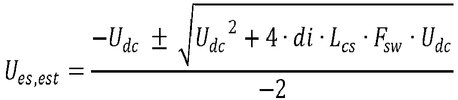
- Ues,est = the estimate for the voltage of the direct current supply;
- Udc = a voltage of the second direct current connection;
- di = a magnitude of current pulsation, "peak-to-peak" value;
- Lcs = the inductance of the choke coil system; and
- Fsw = a switching frequency of the DC-to-DC converter system
- With the estimate Ues,est for the voltage of the direct current supply, the controller is adapted to calculate an estimate Pes,est for a power of the direct current supply by an equation Pes,est = Ues,est · Ies, in which Ies is a current of the direct current supply. The current Ies of the direct current supply may be determined by the current measuring system of the DC-to-DC converter assembly, for example.
- Based on the estimate Pes,est for the power of the direct current supply, the controller is adapted to set a power limit for the direct current supply, which is not allowed to be exceeded. The controller is adapted to limit the power of the direct current supply to a desired value by appropriately controlling the controllable semiconductor switches of the DC-to-DC converter system.
- In another embodiment, the controller is adapted to analyse results of the identification mode in order to determine whether components and connections of the choke coil system operate as expected. For example, the identification mode may reveal that choke coils of the choke coil system have different inductances while they should be identical. If the analysis reveals problems, the controller prevents starting of the DC-to-DC converter system and/or notifies an operator of the DC-to-DC converter assembly about the problems.
- It will be obvious to a person skilled in the art that the inventive concept can be implemented in various ways. The invention and its embodiments are not limited to the examples described above but may vary within the scope of the claims.
Claims (13)
- A DC-to-DC converter assembly comprising:a first direct current connection (11);a second direct current connection (12);a DC-to-DC converter system (2) electrically connected between the first direct current connection (11) and the second direct current connection (12);a controller (909) adapted to control the DC-to-DC converter system (2);a choke coil system (4) adapted to limit rate of change of current in the DC-to-DC converter system (2), the choke coil system (4) comprising at least one choke coil (L1, L2, L3);a voltage measuring system (512) adapted for measuring a voltage of the second direct current connection (12); anda current measuring system (504) adapted for measuring current in the choke coil system (4),characterized in that the controller (909) is adapted to provide an identification mode for determining at least one electric property of the choke coil system (4), the identification mode comprising supplying a voltage pulse to the choke coil system (4), wherein the identification mode utilizes information received from the voltage measuring system (512) and the current measuring system (504).
- The DC-to-DC converter assembly according to claim 1, wherein the at least one electric property of the choke coil system (4) comprises at least one of the following: an inductance of the choke coil system (4), and saturation information relating to the choke coil system (4).
- The DC-to-DC converter assembly according to claim 1 or 2, wherein the DC-to-DC converter system (2) comprises a plurality of controllable semiconductor switches (S1-S6), and the voltage pulse is supplied to the choke coil system (4) by controlling at least part of the plurality of controllable semiconductor switches (S1-S6) to a conducting state.
- The DC-to-DC converter assembly according to claim 3, wherein the DC-to-DC converter system (2) comprises a positive busbar (DC+) and a negative busbar (DC-), wherein the voltage pulse is supplied to the choke coil system (4) by electrically connecting the positive busbar (DC+) to the negative busbar (DC-) through at least one choke coil (L1, L2, L3) of the choke coil system (4) by means of at least part of the plurality of controllable semiconductor switches (S1-S6).
- The DC-to-DC converter assembly according to claim 4, wherein there is a smoothing capacitor system (C1) connected electrically between the positive busbar (DC+) and a negative busbar (DC-), a capacitance of the smoothing capacitor system (C1) is greater than or equal to 10µF.
- The DC-to-DC converter assembly according to any one of the preceding claims, wherein a duration of the voltage pulse is less than or equal to 100ms.
- The DC-to-DC converter assembly according to any one of the preceding claims, wherein the DC-to-DC converter assembly comprises a data storage system (808), and the identification mode comprises storing at least one electric property of the choke coil system (4) to the data storage system (808).
- The DC-to-DC converter assembly according to claim 2, wherein the at least one electric property of the choke coil system (4) comprises the saturation information relating to the choke coil system (4), and determining the saturation information comprises supplying a plurality of voltage pulse to the choke coil system (4) in order to define a plurality of inductance values for the choke coil system (4), each of the plurality of inductance values corresponding to a different current value through the choke coil system (4).
- The DC-to-DC converter assembly according to claim 8, wherein determining the saturation information comprises supplying a plurality of voltage pulse to the choke coil system (4) such that a current value through the choke coil system (4) is raised until a determined inductance value for the choke coil system (4) has decreased at least a predetermined portion compared to the maximum value thereof.
- The DC-to-DC converter assembly according to claim 9, wherein the predetermined portion is greater than or equal to 20%.
- The DC-to-DC converter assembly according to any one of the preceding claims, wherein the controller (909) is adapted to determine an electrical state of the DC-to-DC converter assembly during operation thereof, and is adapted to use the at least one electric property of the choke coil system (4) for carrying out said determination.
- The DC-to-DC converter assembly according to any one of the preceding claims, wherein the controller (909) is adapted to use the at least one electric property of the choke coil system (4) in controlling the DC-to-DC converter system (2).
- The DC-to-DC converter assembly according to claim 12, wherein during a normal operation of the DC-to-DC converter assembly, the controller (909) is adapted to limit a current of the DC-to-DC converter system (2) based on the at least one electric property of the choke coil system (4).
Priority Applications (1)
| Application Number | Priority Date | Filing Date | Title |
|---|---|---|---|
| EP21201413.8A EP4164101A1 (en) | 2021-10-07 | 2021-10-07 | Dc-to-dc converter assembly |
Applications Claiming Priority (1)
| Application Number | Priority Date | Filing Date | Title |
|---|---|---|---|
| EP21201413.8A EP4164101A1 (en) | 2021-10-07 | 2021-10-07 | Dc-to-dc converter assembly |
Publications (1)
| Publication Number | Publication Date |
|---|---|
| EP4164101A1 true EP4164101A1 (en) | 2023-04-12 |
Family
ID=78085841
Family Applications (1)
| Application Number | Title | Priority Date | Filing Date |
|---|---|---|---|
| EP21201413.8A Withdrawn EP4164101A1 (en) | 2021-10-07 | 2021-10-07 | Dc-to-dc converter assembly |
Country Status (1)
| Country | Link |
|---|---|
| EP (1) | EP4164101A1 (en) |
Citations (1)
| Publication number | Priority date | Publication date | Assignee | Title |
|---|---|---|---|---|
| US10361554B1 (en) * | 2016-09-27 | 2019-07-23 | Altera Corporation | Techniques for determining inductances |
-
2021
- 2021-10-07 EP EP21201413.8A patent/EP4164101A1/en not_active Withdrawn
Patent Citations (1)
| Publication number | Priority date | Publication date | Assignee | Title |
|---|---|---|---|---|
| US10361554B1 (en) * | 2016-09-27 | 2019-07-23 | Altera Corporation | Techniques for determining inductances |
Similar Documents
| Publication | Publication Date | Title |
|---|---|---|
| US7835166B2 (en) | Method for controlling a polyphase converter with distributed energy stores | |
| US8102687B2 (en) | Control apparatus for controlling power conversion apparatus | |
| US6556462B1 (en) | High power factor converter with a boost circuit having continuous/discontinuous modes | |
| US5568035A (en) | Variable-capacitance power supply apparatus | |
| US4293812A (en) | Controlled d-c current supply system, with controlled current flow through a choke | |
| US20030026111A1 (en) | Power-electronic circuit arrangement, and a method for transmitting real power | |
| EP2099116B1 (en) | Motor driver provided with converter circuit | |
| NL8006259A (en) | DEVICE FOR CONTROLLING POWER SUPPLIED TO A TELEPHONE LINE. | |
| US10024898B2 (en) | System and method for determining inductance in a power converter | |
| AU2015389306B2 (en) | Step-up device and converter device | |
| US3530369A (en) | Regulator apparatus including static switching circuit having mid-tapped inductor | |
| US11033978B2 (en) | Arc voltage sensing and control for a welding apparatus | |
| CN113497556A (en) | DC-DC converter | |
| US10707777B2 (en) | Control of parallel connected power devices | |
| EP2393182A1 (en) | Method and arrangement for balancing voltages of series connection of storage units for electrical energy | |
| US6661205B1 (en) | Capacitor charging method and capacitor charger | |
| EP4164101A1 (en) | Dc-to-dc converter assembly | |
| EP0644648B1 (en) | Control method and apparatus and malefunction detection method and apparatus for AC motor | |
| US20210391791A1 (en) | Power supply system, control device, and method for measuring reactor current | |
| US20180367134A1 (en) | Voltage balancing of voltage source converters | |
| US6452360B1 (en) | Auto tuning and parameter identification of a control circuit | |
| EP4429099A1 (en) | Arrangement for current sharing of parallel-connected inverters | |
| US6359420B1 (en) | Circuit for coupling energy to a pulse forming network or capacitor | |
| JPH0923641A (en) | Switching power supply drive system | |
| EP2015436A1 (en) | Method for obtaining the average current in the inductive element of a DC-DC-converter |
Legal Events
| Date | Code | Title | Description |
|---|---|---|---|
| PUAI | Public reference made under article 153(3) epc to a published international application that has entered the european phase |
Free format text: ORIGINAL CODE: 0009012 |
|
| STAA | Information on the status of an ep patent application or granted ep patent |
Free format text: STATUS: THE APPLICATION HAS BEEN PUBLISHED |
|
| AK | Designated contracting states |
Kind code of ref document: A1 Designated state(s): AL AT BE BG CH CY CZ DE DK EE ES FI FR GB GR HR HU IE IS IT LI LT LU LV MC MK MT NL NO PL PT RO RS SE SI SK SM TR |
|
| STAA | Information on the status of an ep patent application or granted ep patent |
Free format text: STATUS: THE APPLICATION IS DEEMED TO BE WITHDRAWN |
|
| 18D | Application deemed to be withdrawn |
Effective date: 20231013 |