EP4164088A1 - Appareil de charge électrique de navire embarqué à moyenne tension et procédé de charge embarqué - Google Patents
Appareil de charge électrique de navire embarqué à moyenne tension et procédé de charge embarqué Download PDFInfo
- Publication number
- EP4164088A1 EP4164088A1 EP21201926.9A EP21201926A EP4164088A1 EP 4164088 A1 EP4164088 A1 EP 4164088A1 EP 21201926 A EP21201926 A EP 21201926A EP 4164088 A1 EP4164088 A1 EP 4164088A1
- Authority
- EP
- European Patent Office
- Prior art keywords
- voltage
- onboard
- medium
- series
- energy storage
- Prior art date
- Legal status (The legal status is an assumption and is not a legal conclusion. Google has not performed a legal analysis and makes no representation as to the accuracy of the status listed.)
- Pending
Links
- 238000000034 method Methods 0.000 title claims abstract description 45
- 238000004146 energy storage Methods 0.000 claims abstract description 56
- 230000001276 controlling effect Effects 0.000 description 9
- 230000001105 regulatory effect Effects 0.000 description 6
- 230000001419 dependent effect Effects 0.000 description 2
- 238000010079 rubber tapping Methods 0.000 description 2
- 238000006243 chemical reaction Methods 0.000 description 1
- 238000013461 design Methods 0.000 description 1
- 238000010586 diagram Methods 0.000 description 1
- 239000000446 fuel Substances 0.000 description 1
- 238000009434 installation Methods 0.000 description 1
- 238000012423 maintenance Methods 0.000 description 1
- 238000007726 management method Methods 0.000 description 1
- 238000005259 measurement Methods 0.000 description 1
- 238000012546 transfer Methods 0.000 description 1
- 230000001052 transient effect Effects 0.000 description 1
Images


Classifications
-
- H—ELECTRICITY
- H02—GENERATION; CONVERSION OR DISTRIBUTION OF ELECTRIC POWER
- H02J—CIRCUIT ARRANGEMENTS OR SYSTEMS FOR SUPPLYING OR DISTRIBUTING ELECTRIC POWER; SYSTEMS FOR STORING ELECTRIC ENERGY
- H02J7/00—Circuit arrangements for charging or depolarising batteries or for supplying loads from batteries
- H02J7/02—Circuit arrangements for charging or depolarising batteries or for supplying loads from batteries for charging batteries from ac mains by converters
-
- H—ELECTRICITY
- H02—GENERATION; CONVERSION OR DISTRIBUTION OF ELECTRIC POWER
- H02J—CIRCUIT ARRANGEMENTS OR SYSTEMS FOR SUPPLYING OR DISTRIBUTING ELECTRIC POWER; SYSTEMS FOR STORING ELECTRIC ENERGY
- H02J2207/00—Indexing scheme relating to details of circuit arrangements for charging or depolarising batteries or for supplying loads from batteries
- H02J2207/20—Charging or discharging characterised by the power electronics converter
-
- H—ELECTRICITY
- H02—GENERATION; CONVERSION OR DISTRIBUTION OF ELECTRIC POWER
- H02J—CIRCUIT ARRANGEMENTS OR SYSTEMS FOR SUPPLYING OR DISTRIBUTING ELECTRIC POWER; SYSTEMS FOR STORING ELECTRIC ENERGY
- H02J2310/00—The network for supplying or distributing electric power characterised by its spatial reach or by the load
- H02J2310/40—The network being an on-board power network, i.e. within a vehicle
- H02J2310/42—The network being an on-board power network, i.e. within a vehicle for ships or vessels
-
- Y—GENERAL TAGGING OF NEW TECHNOLOGICAL DEVELOPMENTS; GENERAL TAGGING OF CROSS-SECTIONAL TECHNOLOGIES SPANNING OVER SEVERAL SECTIONS OF THE IPC; TECHNICAL SUBJECTS COVERED BY FORMER USPC CROSS-REFERENCE ART COLLECTIONS [XRACs] AND DIGESTS
- Y02—TECHNOLOGIES OR APPLICATIONS FOR MITIGATION OR ADAPTATION AGAINST CLIMATE CHANGE
- Y02T—CLIMATE CHANGE MITIGATION TECHNOLOGIES RELATED TO TRANSPORTATION
- Y02T10/00—Road transport of goods or passengers
- Y02T10/60—Other road transportation technologies with climate change mitigation effect
- Y02T10/70—Energy storage systems for electromobility, e.g. batteries
-
- Y—GENERAL TAGGING OF NEW TECHNOLOGICAL DEVELOPMENTS; GENERAL TAGGING OF CROSS-SECTIONAL TECHNOLOGIES SPANNING OVER SEVERAL SECTIONS OF THE IPC; TECHNICAL SUBJECTS COVERED BY FORMER USPC CROSS-REFERENCE ART COLLECTIONS [XRACs] AND DIGESTS
- Y02—TECHNOLOGIES OR APPLICATIONS FOR MITIGATION OR ADAPTATION AGAINST CLIMATE CHANGE
- Y02T—CLIMATE CHANGE MITIGATION TECHNOLOGIES RELATED TO TRANSPORTATION
- Y02T10/00—Road transport of goods or passengers
- Y02T10/60—Other road transportation technologies with climate change mitigation effect
- Y02T10/7072—Electromobility specific charging systems or methods for batteries, ultracapacitors, supercapacitors or double-layer capacitors
Definitions
- the present invention is related to an onboard medium-voltage vessel electric charging apparatus, according to the preamble of claim 1.
- the present invention is also related to a method for onboard medium-voltage charging of at least one energy storage device onboard a marine vessel, according to the preamble of claim 12.
- DC direct current
- a DC power consumer To utilize the energy from the energy storage device, a DC power consumer must be connected to the energy storage device usually via a marine vessel DC consumer network.
- the marine vessel In order to charge the energy storage device, the marine vessel requires a power conversion stage, converting from an AC (alternating current) grid supply to DC voltage.
- MVAC medium-voltage alternating current
- the mentioned converters also result in power losses and there is a desire to reduce the power losses in the charging circuit as much as possible.
- the main object of the present invention is to provide an onboard medium-voltage vessel electric charging apparatus and method for onboard medium-voltage charging, partly or entirely solving the mentioned drawbacks of prior art, and/or partly or entirely meeting the mentioned needs.
- An object of the present invention is to provide an onboard medium-voltage vessel electric charging apparatus and method for onboard medium-voltage charging reducing the footprint of electrical equipment on a marine vessel.
- An object of the present invention is to provide an onboard medium-voltage vessel electric charging apparatus and method for onboard medium-voltage charging capable of rectification of the AC power supply and delivery of controlled DC current for charging of an onboard energy storage device.
- An object of the present invention is to provide an onboard medium-voltage vessel electric charging apparatus and method for onboard medium-voltage charging using as few active components as possible.
- An object of the present invention is to provide an onboard medium-voltage vessel electric charging apparatus and method for onboard medium-voltage charging resulting in minimum converter derating.
- An object of the present invention is to provide an onboard medium-voltage vessel electric charging apparatus and method for onboard medium-voltage charging requiring less investment and installation costs, as well as maintenance costs, compared to prior art solutions.
- An onboard medium-voltage vessel electric charging apparatus is defined by the technical features of claim 1. Preferable features of the charging apparatus are described in the dependent claims.
- a method for onboard medium-voltage electric charging of at least one onboard energy storage device according to the present invention is defined by the technical features of claim 12. Preferable features of the method are described in the dependent claims.
- An onboard medium-voltage vessel electric charging apparatus is configured for connection to an AC (alternating current) power supply at one side and to at least one onboard energy storage device at the other side, either directly or via a vessel DC (direct current) consumer network.
- the onboard medium-voltage vessel electric charging apparatus comprises a rectifier unit comprising a rectifier transformer and at least one rectifier bridge arranged in series between the AC power supply and the at least one energy storage device or vessel DC consumer network.
- the onboard medium-voltage vessel electric charging apparatus further comprises a controllable compensation unit arranged in series between the rectifier unit, vessel DC consumer network or at least one energy storage device and the AC power supply, in front of the rectifier transformer.
- the controllable compensation unit according to the present invention is configured to compensate for voltage variations of the vessel DC consumer network or at least one energy storage device by adding a series voltage phasor with different amplitude and phase angle to supplied AC voltage to adjust rectifier voltage of the rectifier unit.
- the mentioned rectifier unit and controllable compensation unit thus forms a charging circuit for charging of the at least one onboard energy storage device.
- the rectifier transformer is a Medium-Voltage to Low-Voltage AC transformer.
- controllable compensation unit comprises a compensation transformer arranged in series between the AC power supply and rectifier transformer of the rectifier unit.
- the controllable compensation unit further comprises at least one controllable compensation converter arranged in series between the at least one rectifier bridge of the rectifier unit, vessel DC consumer network or at least one energy storage device and the compensation transformer.
- controllable compensation converter is a Low-Voltage converter.
- the at least one compensation unit is configured to provide the series voltage phasor amplitude as a symmetric or asymmetric range of required DC-voltage to the vessel DC consumer network or at least one energy storage device.
- the symmetric range of the series voltage phasor amplitude is between -15 % to 15 %, more preferably between -10 % to 10 % of the required DC-voltage.
- the example ranges are not to be considered as limiting for the present invention, as these are only examples and other ranges will be within the knowledge of a skilled person.
- the asymmetric range of the series voltage phasor amplitude is between -30 to 0%, more preferably between -20 % to 0 %, of the required DC-voltage.
- the example ranges are not to be considered as limiting for the present invention, as these are only examples and other ranges will be within the knowledge of a skilled person.
- the onboard medium-voltage vessel electric charging apparatus is configured for scalar or vector control of the series voltage phasor amplitude and phase angle.
- the series voltage phasor amplitude and phase angle are continuously controlled.
- the series voltage phasor amplitude and phase angle are continuously controlled over the charging time based on the grid voltage, energy storage device voltage, and charging power set point.
- a method for onboard medium-voltage electric charging of at least one onboard energy storage device of a marine vessel from an AC power supply comprises charging the at least one onboard energy storage device directly or via a vessel DC consumer network by a rectifier transformer and rectifier unit arranged in series between the AC power supply and the at least one energy storage device.
- the method further comprises compensating for voltage variations of the vessel DC consumer network or at least one onboard energy storage device by adding a series voltage phasor with different amplitude and phase angle to supplied AC voltage to adjust rectifier voltage of the rectifier unit.
- the method according to one embodiment of the present invention comprises adding the series voltage phasor amplitude as a symmetric or asymmetric range of required DC-voltage to the vessel DC consumer network or at least one onboard energy storage device.
- the method according to the present invention comprises using a symmetric range of the series voltage phasor amplitude between -15 % to 15 %, more preferably between -10 % to 10 % of the required DC-voltage.
- the example ranges are not to be considered as limiting for the present invention, as these are only examples and other ranges will be within the knowledge of a skilled person.
- the method comprises using an asymmetric range of the series voltage phasor between -30% to 0%, more preferably between -20 % to 0 %, of the required DC-voltage.
- the example ranges are not to be considered as limiting for the present invention, as these are only examples and other ranges will be within the knowledge of a skilled person.
- the method comprises controlling the series voltage phasor amplitude and phase angle by scalar control or vector control.
- the method comprises continuously controlling the series voltage phasor amplitude and phase angle.
- the method comprises continuously controlling the series voltage phasor amplitude and phase angle over the charging time based on grid voltage, energy storage device voltage, and charging power set point.
- the onboard medium-voltage electric charging apparatus and method for onboard charging according to the present invention is provided a solution wherein one may use mostly passive components and wherein only the compensation converter will have to be active for performing voltage adjustment.
- the onboard medium-voltage charging apparatus and method for onboard charging according to present invention provides a solution wherein the marine vessel can connect to a standard MVAC (medium-voltage alternating current) grid and independently regulate its charging power based on the available power from the grid.
- MVAC medium-voltage alternating current
- the present invention provides a solution where a wide range of energy storage device voltage variations during charging can be compensated for.
- the present invention provides a solution where one may use compact, cheap and efficient diode rectifiers instead of costly active front-end converters.
- the present invention is limiting the volume and footprint of electrical equipment required on the marine vessel.
- an apparatus and method that are capable of rectification of the AC power supply and delivery of controlled DC current for charging of the at least one onboard energy storage device.
- the present invention also provides a voltage adjustment over a wider range, compared to prior art solutions.
- the present invention deals with power regulation using the series compensation, while DC decoupling is done naturally by the galvanically isolating transformers onboard.
- the present invention targets active power control to regulate energy storage device charging power while regulating the reactive power as well to optimize the converter operating point.
- the present invention is provided an electrical configuration and control system onboard the marine vessel that makes the marine vessel independent from specific charging stations.
- the marine vessel will be able to connect to standard Medium Voltage AC networks regulating its charging power independently.
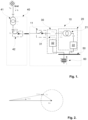
- Fig. 1 a principle drawing of an onboard medium-voltage vessel electric charging apparatus 10 (MVVECA) according to the present invention providing AC (alternating current) voltage adjustment over a wide range.
- MVVECA medium-voltage vessel electric charging apparatus 10
- the onboard MVVECA 10 is adapted to be arranged onboard a marine vessel (not shown) and adapted to be connected to an AC power supply 40 at one side and to at least one onboard energy storage device 60 of the marine vessel at the other side, either directly or via a vessel DC (direct current) consumer network 50, as shown in Fig. 1 .
- the consumer network 50 in the shown example is a DC-distribution system.
- the AC power supply 40 is e.g. an AC shore power grid.
- the DC-distribution system 50 is arranged to an energy storage device 60 formed by batteries. Intelligent charging electronics, can of course, be arranged between the DC-distribution system 50 and the energy storage device 60.
- the onboard MVVECA 10 comprises a rectifier unit 20 arranged between the AC power supply 40 and the at least one energy storage device 60 or vessel DC-consumer network 50.
- the rectifier unit 20 comprises a rectifier transformer 21, e.g. a DFE (Diode front end), and at least one rectifier bridge 22 arranged in series between the AC power supply 40 and the at least one energy storage device 60 or vessel DC consumer network 50.
- the rectifier transformer 21 is according to the present invention a MV (Medium Voltage) to LV (Low Voltage) transformer 21 and connected to the AC power supply 40 at one side.
- the at least one rectifier bridge 22 is according to the present invention preferably a diode rectifier.
- the onboard MVVECA 10 further comprises at least one controllable compensation unit 30 arranged in series between the rectifier unit 20 and the AC power supply 40, i.e. in front of the rectifier transformer 21 of the rectifier unit 20.
- the controllable compensation unit 30 according to the present invention comprises a compensation transformer 31, arranged in series between the AC power supply 40 and the rectifier transformer 21 of the rectifier unit 20.
- the controllable compensation unit 30 according to the present invention further comprises a controllable compensation converter 32, e.g. an AFE (active front end), arranged in series between the compensation transformer 41 and the rectifier bridge 22, vessel DC consumer network 50 or at least one energy storage device 60.
- the controllable compensation converter 32 is a LV (Low Voltage) converter.
- the mentioned controllable compensation unit 30 and rectifier unit 20 thus forms a controllable charging circuit for the at least one energy storage device 60.
- the onboard MVVECA 10 preferably comprises a controllable switch 11 for connection and disconnection of the onboard MVVECA 10 to the AC power supply 40.
- An AC grid will typically deliver high voltage
- the AC power supply 40 is according to one embodiment of the present invention comprising a HV to MV transformer 41 to transform the high AC voltage to a medium AC voltage suitable for supplying to a marine vessel and thus the onboard MVVECA 10 according to the present invention.
- the AC power supply 40 supplies a voltage V v and a current I v to the marine vessel and thus onboard MVVECA 10 according to the present invention.
- a controllable switch 42 is arranged at the output of the AC power supply 40.
- the cheapest devices to charge energy storage devices 60 from the AC power supply 40 are diode rectifiers. However, as the energy storage device 60 voltage varies in a wide range during the charging cycle, the diode rectifiers need an adjustable AC voltage varying with V DC to regulate the power.
- the series compensation according to the present invention provides an excellent possibility for AC voltage adjustment over a wide range.
- At least one compensation unit 30 By arranging at least one compensation unit 30 in series with the MV part of the AC power supply 40, wherein the current is low, this will enable the possibility to regulate large power flows with at least one controllable low voltage compensation converter 31. Accordingly, by the present invention the costly active front-ends on LV side of the rectifier unit 20 can be replaced by their compact, cheap, and efficient counterparts, diode bridges 22.
- the compensation unit 30 is adapted to add a series voltage phasor V s with different amplitudes and phase angles to the supplied medium AC voltage V v of the AC power supply 40 to adjust the rectifier voltage V rec supplied to the rectifier unit 20.
- Fig. 2 is a principle drawing of the control principle according to the present invention.
- the at least one controllable compensation converter 32 according to the present invention is able to apply any voltage vector within the dashed circle shown in the figure. However, any voltage within this dashed circle is not viable in practice, as it could lead to overcurrent or instability.
- the voltage of each device could independently vary, while their currents are equal. Accordingly, by the at least one controllable compensation converter 32 regulating its own current, the at least one controllable compensation converter 32 will regulate the currents of other devices/components of the onboard MVVECA 10 and consequently their active and reactive powers (as long as the AC power supply 40 is strong enough to maintain the voltage).
- the at least one controllable compensation converter 32 is configured to provide a voltage window of around 20 % range of the V DC and configured to adapt the AC voltage V rec supplied to the rectifier unit 20 by adding an adapted series voltage phasor V s to the supplied voltage V v of the AC power supply 40.
- the ranges may vary depending on the application and specifications of the system.
- the optimal design/operating conditions of the controllable compensation unit 30 is when the series voltage phasor V s vector is approximately aligned with the rectifier voltage vector V rec supplied to the rectifier unit 20.
- the required series voltage phasor V s amplitude is at the lowest, while the compensation unit 30 by the least one controllable compensation converter 32 contributes mainly with active power. Both of these conditions provide minimum converter derating.
- Fig. 3a-b showing a principle drawing of an embodiment of the present invention wherein the controllable compensation unit 30 is configured to provide a series voltage phasor V s amplitude varying from -20 % to 0 % of the V DC
- Fig. 4a-b showing a principle drawing of an embodiment of the present invention where the controllable compensation unit 40 is configured to provide a series voltage phasor V s amplitude varying from -10 % to 10 % of the V DC .
- the main advantage of the embodiment of Fig. 3a-b over the embodiment of Fig. 4a-b is that in the first embodiment one avoids circulating currents.
- the embodiment of Fig. 3a-b further have some disadvantages in relation to the embodiment of Fig. 4a-b .
- the compensation transformer 31 primary voltage (and power) and secondary current will be doubled compared with the embodiment of Fig. 4a-b . Accordingly, in the embodiment of Fig. 3a-b , double AFEs (Active Front End) are needed compared to the embodiment of Fig. 4a-b .
- One advantage of the embodiment of Fig. 4a-b over the embodiment of Fig. 3a-b is that the number of AFEs required is reduced. An equivalently rated DFE (Diode front end) needs to be added on DFE side instead, which is less costly than the AFE.
- the solution of the embodiment of Fig. 4a-b further results in lower losses compared to the solution of the embodiment of Fig. 3a-b .
- a further advantage with the embodiment of Fig. 4a-b is that the compensation transformer 31 will only be required to be half the size of the compensation transformer 31 of the embodiment in Fig. 3a-b . Accordingly, the embodiment of Fig. 4a-b in addition to the mentioned advantages requires less space than the embodiment of Fig. 3a-b .
- a disadvantage of solution of Fig. 4a-b in relation to Fig. 3a-b is that one during half of the charging cycle of the energy storage device 60 will have circulating current.
- a further disadvantage compared to the embodiment of Fig. 3a-b is slightly larger DFE/rectifier transformer 21.
- the onboard MVVECA 10 comprises a control device 100 provided with means and/or software for controlling the compensation unit 30 by finding/calculating the correct voltage under each condition to maintain all components of the onboard MVVECA 10 within their limits.
- the onboard MVVECA 10 is further preferably provided with one or more sensors and/or battery management system or other intelligent charging electronics to provide measurements of V DC , V v , I rec and V rec as input to the control device 100.
- the controllable converter 32 is arranged to provide measures of I converter and V converter as input to the control device 100.
- the mentioned control device 100 is provided with means and/or software for scalar control or vector control of the compensation unit 30, as described above.
- the control device 100 is adapted to control/setting the current as the control variable of the at least one controllable compensation converter 32 of the compensation unit 30.
- the control device 100 is adapted for scalar control by adjusting series voltage phasor V s amplitude and phase angle to be provided by the controllable compensation unit 30 to regulate active and reactive powers and indirectly regulate the rectifier unit 20 current I rec .
- the slow dynamics of this control method particularly when the series voltage phasor V s is close to zero, makes it prone to instability.
- the control device 100 is adapted for vector control, as shown in Fig. 6 , by control in d-q coordinate, which results in a much faster dynamics, compared to the scalar control method, while it is straightforward for this configuration.
- the key of the vector control method is to align the d-axis with the supplied AC V v from the AC power supply 40. Then, the d-axis current will be the active component of the rectifier unit 20 current l rec .
- the control device 100 will be adapted to use I d as control variable to regulate the charging power (active power) of the controllable compensation unit 30 and I q as control variable to maintain power factor of the inverter bridge of the at least one controllable compensation converter 32 at unity. By the latter one will achieve minimum derating of the at least one controllable compensation converter 32.
- the control device 100 is configured to/provided with means and/or software for continuously controlling the series voltage phasor V s amplitude and phase angle.
- the control device 100 is configured to/provided with means and/or software for continuously controlling the series voltage phasor V s amplitude and phase angle over the charging time based on grid voltage, energy storage device voltage, and charging power set point.
- a charging power of up to 10 MW can be regulated by a single 1700 kW rectifier bridge 22 due to the series configuration of the controllable compensation unit 30 according to the present invention.
- Short circuit voltage (uk%), secondary and primary voltages, and tapping of different transformers are important parameters in an optimized configuration of the onboard MVVECA 10.
- An example of a cost-effective configuration is when the vessel voltage V v is set at 0.9 pu, series voltage V s at 0.1 pu, and transformer 21 and 31 tappings are adjusted to compensate for the voltage drops across uk% of the transformers 21 and 31.
- the controllable compensation unit 30 is sensitive to overmodulation and m > 1.15 should be avoided even in transient; otherwise the system will become unstable. Therefore, the passive components of the onboard MVVECA 10 should be designed in such a way that m is strictly maintained below 1.15 in all conditions.
- the above described rectifier bridge 22 can be formed by one or more sub-rectifiers arranged in series or parallel configuration.
- controllable compensation converter 32 can be formed by one or more sub-AFEs arranged in series or parallel configuration.
- the present invention is applicable for marine vessel-to-vessel power transfer.
Landscapes
- Engineering & Computer Science (AREA)
- Power Engineering (AREA)
- Charge And Discharge Circuits For Batteries Or The Like (AREA)
Priority Applications (1)
| Application Number | Priority Date | Filing Date | Title |
|---|---|---|---|
| EP21201926.9A EP4164088A1 (fr) | 2021-10-11 | 2021-10-11 | Appareil de charge électrique de navire embarqué à moyenne tension et procédé de charge embarqué |
Applications Claiming Priority (1)
| Application Number | Priority Date | Filing Date | Title |
|---|---|---|---|
| EP21201926.9A EP4164088A1 (fr) | 2021-10-11 | 2021-10-11 | Appareil de charge électrique de navire embarqué à moyenne tension et procédé de charge embarqué |
Publications (1)
| Publication Number | Publication Date |
|---|---|
| EP4164088A1 true EP4164088A1 (fr) | 2023-04-12 |
Family
ID=78087179
Family Applications (1)
| Application Number | Title | Priority Date | Filing Date |
|---|---|---|---|
| EP21201926.9A Pending EP4164088A1 (fr) | 2021-10-11 | 2021-10-11 | Appareil de charge électrique de navire embarqué à moyenne tension et procédé de charge embarqué |
Country Status (1)
| Country | Link |
|---|---|
| EP (1) | EP4164088A1 (fr) |
Citations (4)
| Publication number | Priority date | Publication date | Assignee | Title |
|---|---|---|---|---|
| US6331765B1 (en) | 1999-02-25 | 2001-12-18 | Kabushiki Kaisha Toshiba | Series compensator |
| US20130016541A1 (en) | 2010-03-04 | 2013-01-17 | Abb Research Ltd | Ac/dc converter station and a method of operating an ac/dc converter station |
| WO2018202462A1 (fr) * | 2017-05-05 | 2018-11-08 | Siemens Aktiengesellschaft | Système et procédé de charge électrique |
| FR3070911A1 (fr) * | 2017-09-12 | 2019-03-15 | Valeo Systemes De Controle Moteur | Chargeur de vehicule comprenant un convertisseur dc/dc |
-
2021
- 2021-10-11 EP EP21201926.9A patent/EP4164088A1/fr active Pending
Patent Citations (5)
| Publication number | Priority date | Publication date | Assignee | Title |
|---|---|---|---|---|
| US6331765B1 (en) | 1999-02-25 | 2001-12-18 | Kabushiki Kaisha Toshiba | Series compensator |
| US20130016541A1 (en) | 2010-03-04 | 2013-01-17 | Abb Research Ltd | Ac/dc converter station and a method of operating an ac/dc converter station |
| WO2018202462A1 (fr) * | 2017-05-05 | 2018-11-08 | Siemens Aktiengesellschaft | Système et procédé de charge électrique |
| US20200189404A1 (en) | 2017-05-05 | 2020-06-18 | Siemens Aktiengesellschaft | Electric charging system and method |
| FR3070911A1 (fr) * | 2017-09-12 | 2019-03-15 | Valeo Systemes De Controle Moteur | Chargeur de vehicule comprenant un convertisseur dc/dc |
Similar Documents
| Publication | Publication Date | Title |
|---|---|---|
| EP3619787B1 (fr) | Système et procédé de recharge électrique | |
| US8546976B2 (en) | System and apparatus for power transfer to vessels | |
| US11239663B2 (en) | Energy storage device and power system and control method thereof | |
| US11799293B2 (en) | High-voltage DC transformation apparatus and power system and control method thereof | |
| US7596002B2 (en) | Power conversion system and method | |
| US5694306A (en) | Method and device for control of a series-compensated converter station | |
| CN103825278A (zh) | 功率质量控制 | |
| EP2975753A1 (fr) | Convertisseur à trois niveaux | |
| US10958068B2 (en) | DC transmission system and DC/DC converter used in the same | |
| US11811310B2 (en) | Power conversion system and control method | |
| EP2495864B1 (fr) | Agencement de contrôle et procédé de régulation du courant de sortie d'un convertisseur de puissance de source cc connecté à un système cc multi-source | |
| US20240162705A1 (en) | Method for operating an energy supply system, device for exchanging electrical power in an energy supply system, and energy supply system | |
| US3932799A (en) | Peak load levelling system | |
| US20220311337A1 (en) | Voltage balance systems and methods for multilevel converters | |
| US4649466A (en) | Method and circuit arrangemeant for operating a high voltage direct current line between two alternating voltage systems | |
| RU2543507C1 (ru) | Устройство для зарядки аккумуляторной батареи подводного объекта | |
| EA028401B1 (ru) | Управляемый подмагничиванием шунтирующий реактор (варианты) | |
| EP4164088A1 (fr) | Appareil de charge électrique de navire embarqué à moyenne tension et procédé de charge embarqué | |
| WO2023063830A1 (fr) | Appareil de charge électrique de récipient à moyenne tension embarqué et procédé de charge embarquée | |
| RU2367082C1 (ru) | Способ регулирования напряжения и устройство трехфазного выпрямителя | |
| US3612897A (en) | Arrangement for tapping the dc link of a high-voltage direct current transmission system | |
| CN118119526A (zh) | 船载中压船舶充电设备和船载充电方法 | |
| EP3985821A1 (fr) | Réseau électrique | |
| US10938213B2 (en) | Power transmission via a bipolar high-voltage DC transmission link | |
| CN105717388A (zh) | 一种变压器测试平台 |
Legal Events
| Date | Code | Title | Description |
|---|---|---|---|
| PUAI | Public reference made under article 153(3) epc to a published international application that has entered the european phase |
Free format text: ORIGINAL CODE: 0009012 |
|
| STAA | Information on the status of an ep patent application or granted ep patent |
Free format text: STATUS: THE APPLICATION HAS BEEN PUBLISHED |
|
| AK | Designated contracting states |
Kind code of ref document: A1 Designated state(s): AL AT BE BG CH CY CZ DE DK EE ES FI FR GB GR HR HU IE IS IT LI LT LU LV MC MK MT NL NO PL PT RO RS SE SI SK SM TR |
|
| P01 | Opt-out of the competence of the unified patent court (upc) registered |
Effective date: 20230526 |
|
| STAA | Information on the status of an ep patent application or granted ep patent |
Free format text: STATUS: REQUEST FOR EXAMINATION WAS MADE |
|
| 17P | Request for examination filed |
Effective date: 20231011 |
|
| RBV | Designated contracting states (corrected) |
Designated state(s): AL AT BE BG CH CY CZ DE DK EE ES FI FR GB GR HR HU IE IS IT LI LT LU LV MC MK MT NL NO PL PT RO RS SE SI SK SM TR |