EP4164068A1 - Connector plug, abutting structure of the same, and electrical connection mechanism having the same - Google Patents
Connector plug, abutting structure of the same, and electrical connection mechanism having the same Download PDFInfo
- Publication number
- EP4164068A1 EP4164068A1 EP22187225.2A EP22187225A EP4164068A1 EP 4164068 A1 EP4164068 A1 EP 4164068A1 EP 22187225 A EP22187225 A EP 22187225A EP 4164068 A1 EP4164068 A1 EP 4164068A1
- Authority
- EP
- European Patent Office
- Prior art keywords
- outer casing
- connector
- connector plug
- inner casing
- insertion port
- Prior art date
- Legal status (The legal status is an assumption and is not a legal conclusion. Google has not performed a legal analysis and makes no representation as to the accuracy of the status listed.)
- Pending
Links
Images



Classifications
-
- H—ELECTRICITY
- H01—ELECTRIC ELEMENTS
- H01R—ELECTRICALLY-CONDUCTIVE CONNECTIONS; STRUCTURAL ASSOCIATIONS OF A PLURALITY OF MUTUALLY-INSULATED ELECTRICAL CONNECTING ELEMENTS; COUPLING DEVICES; CURRENT COLLECTORS
- H01R13/00—Details of coupling devices of the kinds covered by groups H01R12/70 or H01R24/00 - H01R33/00
- H01R13/46—Bases; Cases
- H01R13/516—Means for holding or embracing insulating body, e.g. casing, hoods
-
- H—ELECTRICITY
- H01—ELECTRIC ELEMENTS
- H01R—ELECTRICALLY-CONDUCTIVE CONNECTIONS; STRUCTURAL ASSOCIATIONS OF A PLURALITY OF MUTUALLY-INSULATED ELECTRICAL CONNECTING ELEMENTS; COUPLING DEVICES; CURRENT COLLECTORS
- H01R13/00—Details of coupling devices of the kinds covered by groups H01R12/70 or H01R24/00 - H01R33/00
- H01R13/62—Means for facilitating engagement or disengagement of coupling parts or for holding them in engagement
- H01R13/627—Snap or like fastening
- H01R13/6271—Latching means integral with the housing
- H01R13/6273—Latching means integral with the housing comprising two latching arms
-
- H—ELECTRICITY
- H01—ELECTRIC ELEMENTS
- H01R—ELECTRICALLY-CONDUCTIVE CONNECTIONS; STRUCTURAL ASSOCIATIONS OF A PLURALITY OF MUTUALLY-INSULATED ELECTRICAL CONNECTING ELEMENTS; COUPLING DEVICES; CURRENT COLLECTORS
- H01R13/00—Details of coupling devices of the kinds covered by groups H01R12/70 or H01R24/00 - H01R33/00
- H01R13/46—Bases; Cases
- H01R13/502—Bases; Cases composed of different pieces
- H01R13/5025—Bases; Cases composed of different pieces one or more pieces being of resilient material
-
- H—ELECTRICITY
- H01—ELECTRIC ELEMENTS
- H01R—ELECTRICALLY-CONDUCTIVE CONNECTIONS; STRUCTURAL ASSOCIATIONS OF A PLURALITY OF MUTUALLY-INSULATED ELECTRICAL CONNECTING ELEMENTS; COUPLING DEVICES; CURRENT COLLECTORS
- H01R13/00—Details of coupling devices of the kinds covered by groups H01R12/70 or H01R24/00 - H01R33/00
- H01R13/46—Bases; Cases
- H01R13/502—Bases; Cases composed of different pieces
- H01R13/506—Bases; Cases composed of different pieces assembled by snap action of the parts
-
- H—ELECTRICITY
- H01—ELECTRIC ELEMENTS
- H01R—ELECTRICALLY-CONDUCTIVE CONNECTIONS; STRUCTURAL ASSOCIATIONS OF A PLURALITY OF MUTUALLY-INSULATED ELECTRICAL CONNECTING ELEMENTS; COUPLING DEVICES; CURRENT COLLECTORS
- H01R13/00—Details of coupling devices of the kinds covered by groups H01R12/70 or H01R24/00 - H01R33/00
- H01R13/62—Means for facilitating engagement or disengagement of coupling parts or for holding them in engagement
- H01R13/627—Snap or like fastening
- H01R13/6275—Latching arms not integral with the housing
Definitions
- the present disclosure relates to connectors and, more particularly, to a connector plug, an abutting structure of a connector plug, and an electrical connection mechanism having a connector plug.
- USB Type-C Universal specification
- USB Type-C Universal specification
- the present disclosure provides an external reinforcement structure conducive to the application of connectors with universal specification to the aforesaid scenarios which have stringent usage requirements.
- the present disclosure is further designed to ensure the abutting firmness of connectors.
- Another objective of the present disclosure is to provide a connector plug, an abutting structure of a connector plug, and an electrical connection mechanism having a connector plug, which comply with universal specification, such as USB Type-C specification.
- a connector plug comprising a connection body and an outer casing member.
- the connection body has a connector and a terminal member extending to a terminal end of the connector.
- the terminal member comprises a cable electrically connected to the connector and a sheath portion enclosing the cable.
- the outer casing member comprises an inner casing and an outer casing enclosing the inner casing.
- the inner casing fits to the sheath portion from outside.
- a circular sidewall at a front end of the inner casing defines an insertion port.
- the insertion port protrudes from a front end of the outer casing when the connector protrudes from a front end of the sheath portion and reaches an interior of the insertion port.
- At least one engaging arm is disposed on the inner casing and has a pressing portion protruding from the outer casing and an engaging portion extending forward from the pressing portion and hanging above a sidewall of the insertion port.
- the present disclosure provides an abutting structure of a connector plug, comprising a plug and a receptacle.
- the plug comprises a connection body and an outer casing member disposed outside the connection body.
- the outer casing member further comprises an inner casing and an outer casing enclosing the inner casing.
- a circular sidewall at a front end of the inner casing defines an insertion port.
- At least one engaging arm is disposed on the inner casing and has a pressing portion protruding from the outer casing and an engaging portion protruding forward from the pressing portion and hanging above the sidewall of the insertion port.
- the receptacle comprises an abutting body and an abutting outer casing.
- the abutting outer casing has an insertion opening.
- the sidewall of the inner casing is inserted into the insertion opening, and the abutting body reaches the interior of the insertion opening, wherein the abutting outer casing has at least one engaging hole.
- the abutting outer casing has at least one engaging hole. The engaging portion becomes engaged with the engaging hole as the connection body is inserted into the abutting body.
- an electrical connection mechanism having a connector plug and comprising a cable and a plug.
- the plug is disposed at one end of the cable and comprises a connection body electrically connected to the cable and an outer casing member disposed outside the connection body.
- the outer casing member comprises an inner casing and an outer casing enclosing the inner casing.
- a circular sidewall at a front end of the inner casing defines an insertion port.
- At least one engaging arm is disposed on the inner casing and has a pressing portion protruding from the outer casing and an engaging portion extending forward from the pressing portion and hanging above the sidewall of the insertion port.
- FIG. 1 there is shown an exploded view of a plug and a receptacle of the present disclosure.
- the present disclosure provides a connector plug, an abutting structure of the same, and an electrical connection mechanism having the same.
- a connector plug 1 is plugged into a receptacle 2.
- the connector plug 1 comprises a connection body 10 and an outer casing member 11 disposed outside the connection body 10.
- the connection body 10 has a connector 100 and a terminal member 101 extended to the terminal end of the connector 100.
- the connector 100 of the connector plug 1 is a connector with universal specification, such as USB Type-C specification, and is a female end of the specification.
- the terminal member 101 comprises a cable 102 electrically connected to the connector 100 of the connector plug 1 and a sheath portion 103 enclosing the cable 102.
- the electrical connection mechanism of the present disclosure is constructed by providing the connector plug 1 at one end of the cable 102, with the cable 102 electrically connected to the connection body 10. Depending on product needs, either connectors (not shown) with identical or different specifications are disposed at the other end of the cable 102, or the other end of the cable 102 is directly connected to a required apparatus (not shown).
- the outer casing member 11 comprises an inner casing 110 and an outer casing 111 enclosing the inner casing 110.
- the inner casing 110 fits to the sheath portion 103 of the connection body 10 from outside.
- the front end of the inner casing 110 has an insertion port 112 protruding from the front end of the outer casing 111.
- the insertion port 112 is an opening formed by a circular sidewall of the inner casing 110.
- the connector 100 of the connector plug 1 protrudes from the front end of the sheath portion 103 to thereby reach the interior of the insertion port 112.
- the receptacle 2 comprises an abutting body 20 and an abutting outer casing 21.
- the abutting body 20 has a connector 200 with universal specification, such as Type-C specification or the like.
- the connector 200 enables the connector plug 1 to achieve electrical connection.
- the abutting outer casing 21 has an insertion opening 210.
- the abutting body 20 is adapted to enter the insertion opening 210 smoothly in a way facilitated by the outline of the anterior sidewall of the inner casing 110 of the connector plug 1, so as to achieve the electrical connection of the connector 200 of the receptacle 2 and the connector 100 of the connector plug 1.
- the present disclosure is advantageous in that at least one engaging arm 113 is disposed on the inner casing 110 of the connector plug 1.
- the engaging arm 113 has a pressing portion 113a protruding upward from the outer casing 111 and an engaging portion 113b extending forward from the pressing portion 113a and hanging above the sidewall of the insertion port 112.
- At least one engaging hole 211 is disposed on the abutting outer casing 21 of the receptacle 2 and corresponds in position to the engaging portion 113b of the engaging arm 113; thus, the engaging portion 113b becomes engaged with the engaging hole 211 as the connector 100 of the connector plug 1 is inserted into the connector 200 of the receptacle 2.
- FIG. 1 As shown in FIG.
- a groove is defined on the sidewall of the insertion port 112 and adapted to hang the engaging portion 113b.
- the groove is of a length which can be increased according to the position of the pressing portion 113a and can be designed according to the pressing depth of the pressing portion 113a.
- at least one channel 103a is arranged on the sheath portion 103 and corresponds in position to the pressing portion 113a from below, thereby increasing the room for pressing the pressing portion 113a downward.
- two guide portions 212 are disposed in the insertion opening 210 of the abutting outer casing 21 of the receptacle 2 and correspond in position to two sides of the connector 200 of the receptacle 2, respectively, to facilitate the alignment and guidance required for the insertion of the connector 100 of the connector plug 1.
- the engaging arms 113 are in the number of two and are disposed on two opposite sidewalls of the insertion port 112, respectively; and, as shown in FIG. 3 , the engaging holes 211 are also in the number of two and are disposed at corresponding positions, respectively.
- the inner casing 110 is inserted into the front end of the outer casing 111, whereas the front edge of the outer casing 111 dents to form a notch 111a corresponding in position to the pressing portion 113a of the engaging arm 113, such that the pressing portion 113a becomes received in the notch 111a as the inner casing 110 is inserted into the front end of the outer casing 111.
- An engaging aperture 111b is defined at each of the two ends of the front edge of the outer casing 111 and corresponds in position to a bump 110c disposed at the inner casing 110.
- the cable 102 has a buffer structure 104 located at the terminal end of the outer casing member 11 of the connector plug 1; the buffer structure 104 is made by plastic injection molding and disposed between the cable 102 and the terminal end of the sheath portion 103; an inner link ring 110d is disposed at the terminal end of the inner casing 110; an outer link ring 111c is disposed at the terminal end of the outer casing 111; after the inner casing 110 and the outer casing 111 have been coupled together, the outer link ring 111c is fitted to the inner link ring 110d, allowing the outer link ring 111c to be coupled to the front edge of the buffer structure 104.
- the present disclosure achieves anticipated objectives of use and overcomes drawbacks of prior art. Furthermore, the present disclosure has novelty and inventiveness and thus meets patentability requirements. Therefore, a patent application is filed according to the Patent Act, and granting the application with patent rights is respectfully requested to ensure rights of the Inventor.
Landscapes
- Details Of Connecting Devices For Male And Female Coupling (AREA)
Abstract
Description
- The application claims priority to
U.S. Provisional Application No. 63/226,543, filed on July 28, 2021 - The present disclosure relates to connectors and, more particularly, to a connector plug, an abutting structure of a connector plug, and an electrical connection mechanism having a connector plug.
- To prevent glitches, such as a loosened connector otherwise required for signal or data transmission, conventional industrial computers applicable to vehicles or operating in compliance with special standards or military standards, usually come with a specially-designed connector plugging structure, albeit limiting the scope of their application because of an eclectic mix of specifications.
- Universal specification, such as USB Type-C specification, is conveniently available to conventional connectors but render it difficult to alter the plugging structures of the conventional connectors for use with the industrial computers in accordance with their stringent usage requirements. In view of this, the present disclosure provides an external reinforcement structure conducive to the application of connectors with universal specification to the aforesaid scenarios which have stringent usage requirements.
- The present disclosure is further designed to ensure the abutting firmness of connectors.
- It is an objective of the present disclosure to provide a connector plug, an abutting structure of a connector plug, and an electrical connection mechanism having a connector plug, all adapted to achieve structural reinforcement of connector casings while keeping their universal specification intact, and characterized by an engagement design whereby an abutting structure can be firmly fastened in place in the course of plugging, so as to prevent detachment of connectors in the course of male-female plugging.
- Another objective of the present disclosure is to provide a connector plug, an abutting structure of a connector plug, and an electrical connection mechanism having a connector plug, which comply with universal specification, such as USB Type-C specification.
- In order to achieve the above and other objectives, the present disclosure provides a connector plug, comprising a connection body and an outer casing member. The connection body has a connector and a terminal member extending to a terminal end of the connector. The terminal member comprises a cable electrically connected to the connector and a sheath portion enclosing the cable. The outer casing member comprises an inner casing and an outer casing enclosing the inner casing. The inner casing fits to the sheath portion from outside. A circular sidewall at a front end of the inner casing defines an insertion port. The insertion port protrudes from a front end of the outer casing when the connector protrudes from a front end of the sheath portion and reaches an interior of the insertion port. At least one engaging arm is disposed on the inner casing and has a pressing portion protruding from the outer casing and an engaging portion extending forward from the pressing portion and hanging above a sidewall of the insertion port.
- In order to achieve the above and other objectives, the present disclosure provides an abutting structure of a connector plug, comprising a plug and a receptacle. The plug comprises a connection body and an outer casing member disposed outside the connection body. The outer casing member further comprises an inner casing and an outer casing enclosing the inner casing. A circular sidewall at a front end of the inner casing defines an insertion port. At least one engaging arm is disposed on the inner casing and has a pressing portion protruding from the outer casing and an engaging portion protruding forward from the pressing portion and hanging above the sidewall of the insertion port. The receptacle comprises an abutting body and an abutting outer casing. The abutting outer casing has an insertion opening. The sidewall of the inner casing is inserted into the insertion opening, and the abutting body reaches the interior of the insertion opening, wherein the abutting outer casing has at least one engaging hole. The abutting outer casing has at least one engaging hole. The engaging portion becomes engaged with the engaging hole as the connection body is inserted into the abutting body.
- In order to achieve the above and other objectives, the present disclosure provides an electrical connection mechanism having a connector plug and comprising a cable and a plug. The plug is disposed at one end of the cable and comprises a connection body electrically connected to the cable and an outer casing member disposed outside the connection body. The outer casing member comprises an inner casing and an outer casing enclosing the inner casing. A circular sidewall at a front end of the inner casing defines an insertion port. At least one engaging arm is disposed on the inner casing and has a pressing portion protruding from the outer casing and an engaging portion extending forward from the pressing portion and hanging above the sidewall of the insertion port.
-
-
FIG. 1 is an exploded view of a plug and a receptacle of the present disclosure. -
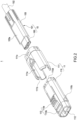
FIG. 2 is an exploded view of the plug of the present disclosure. -
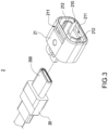
FIG. 3 is an exploded view of the receptacle of the present disclosure. -
FIG. 4 is a cross-sectional view of the receptacle and the plug plugged thereinto according to the present disclosure. -
FIG. 5 is a cross-sectional view of the receptacle and plug separated from each other according to the present disclosure. - Technical features of the present disclosure are depicted by accompanying drawings and described below. However, the accompanying drawings are illustrative rather than restrictive of the present disclosure.
- Referring to
FIG. 1 , there is shown an exploded view of a plug and a receptacle of the present disclosure. The present disclosure provides a connector plug, an abutting structure of the same, and an electrical connection mechanism having the same. Aconnector plug 1 is plugged into areceptacle 2. Referring toFIG. 2 , theconnector plug 1 comprises aconnection body 10 and anouter casing member 11 disposed outside theconnection body 10. - The
connection body 10 has aconnector 100 and aterminal member 101 extended to the terminal end of theconnector 100. In an embodiment of the present disclosure, theconnector 100 of theconnector plug 1 is a connector with universal specification, such as USB Type-C specification, and is a female end of the specification. Theterminal member 101 comprises acable 102 electrically connected to theconnector 100 of theconnector plug 1 and asheath portion 103 enclosing thecable 102. The electrical connection mechanism of the present disclosure is constructed by providing theconnector plug 1 at one end of thecable 102, with thecable 102 electrically connected to theconnection body 10. Depending on product needs, either connectors (not shown) with identical or different specifications are disposed at the other end of thecable 102, or the other end of thecable 102 is directly connected to a required apparatus (not shown). - The
outer casing member 11 comprises aninner casing 110 and anouter casing 111 enclosing theinner casing 110. Theinner casing 110 fits to thesheath portion 103 of theconnection body 10 from outside. The front end of theinner casing 110 has aninsertion port 112 protruding from the front end of theouter casing 111. Theinsertion port 112 is an opening formed by a circular sidewall of theinner casing 110. Theconnector 100 of the connector plug 1 protrudes from the front end of thesheath portion 103 to thereby reach the interior of theinsertion port 112. - Referring to
FIG. 1 andFIG. 3 , thereceptacle 2 comprises anabutting body 20 and an abuttingouter casing 21. Theabutting body 20 has aconnector 200 with universal specification, such as Type-C specification or the like. Theconnector 200 enables theconnector plug 1 to achieve electrical connection. The abuttingouter casing 21 has an insertion opening 210. Theabutting body 20 is adapted to enter the insertion opening 210 smoothly in a way facilitated by the outline of the anterior sidewall of theinner casing 110 of theconnector plug 1, so as to achieve the electrical connection of theconnector 200 of thereceptacle 2 and theconnector 100 of theconnector plug 1. - As shown in
FIG. 1 andFIG. 4 , the present disclosure is advantageous in that at least oneengaging arm 113 is disposed on theinner casing 110 of theconnector plug 1. Theengaging arm 113 has apressing portion 113a protruding upward from theouter casing 111 and anengaging portion 113b extending forward from thepressing portion 113a and hanging above the sidewall of theinsertion port 112. At least oneengaging hole 211 is disposed on the abuttingouter casing 21 of thereceptacle 2 and corresponds in position to theengaging portion 113b of theengaging arm 113; thus, theengaging portion 113b becomes engaged with theengaging hole 211 as theconnector 100 of theconnector plug 1 is inserted into theconnector 200 of thereceptacle 2. As shown inFIG. 2 , a groove is defined on the sidewall of theinsertion port 112 and adapted to hang the engagingportion 113b. The groove is of a length which can be increased according to the position of thepressing portion 113a and can be designed according to the pressing depth of thepressing portion 113a. Referring toFIG. 4 , at least onechannel 103a is arranged on thesheath portion 103 and corresponds in position to thepressing portion 113a from below, thereby increasing the room for pressing thepressing portion 113a downward. Referring toFIG. 3 , twoguide portions 212 are disposed in theinsertion opening 210 of the abuttingouter casing 21 of thereceptacle 2 and correspond in position to two sides of theconnector 200 of thereceptacle 2, respectively, to facilitate the alignment and guidance required for the insertion of theconnector 100 of theconnector plug 1. - Referring to
FIG. 5 , to unplug theconnector plug 1 from thereceptacle 2, a user presses thepressing portion 113a of theengaging arm 113, for example, by hand, to exert a force on theengaging arm 113 and thereby allow theengaging portion 113b to bend inward, deform and separate from the engaginghole 211. It is possible to increase the number of theengaging arm 113. As shown inFIG. 2 , in an embodiment of the present disclosure, the engagingarms 113 are in the number of two and are disposed on two opposite sidewalls of theinsertion port 112, respectively; and, as shown inFIG. 3 , the engagingholes 211 are also in the number of two and are disposed at corresponding positions, respectively. - Referring to
FIG. 2 , in an embodiment of the present disclosure, to couple theinner casing 110 and theouter casing 111 of theconnector plug 1 together, theinner casing 110 is inserted into the front end of theouter casing 111, whereas the front edge of theouter casing 111 dents to form anotch 111a corresponding in position to thepressing portion 113a of theengaging arm 113, such that thepressing portion 113a becomes received in thenotch 111a as theinner casing 110 is inserted into the front end of theouter casing 111. An engagingaperture 111b is defined at each of the two ends of the front edge of theouter casing 111 and corresponds in position to abump 110c disposed at theinner casing 110. Upon insertion of theinner casing 110 into the front end of theouter casing 111, thebumps 110c engagingly enter the engagingapertures 111b, respectively, such that theinner casing 110 and theouter casing 111 are coupled together more firmly. - Referring to
FIG. 1 andFIG. 2 , in addition to the aforesaid technical features of the electrical connection mechanism of the present disclosure, thecable 102 has abuffer structure 104 located at the terminal end of theouter casing member 11 of theconnector plug 1; thebuffer structure 104 is made by plastic injection molding and disposed between thecable 102 and the terminal end of thesheath portion 103; aninner link ring 110d is disposed at the terminal end of theinner casing 110; anouter link ring 111c is disposed at the terminal end of theouter casing 111; after theinner casing 110 and theouter casing 111 have been coupled together, theouter link ring 111c is fitted to theinner link ring 110d, allowing theouter link ring 111c to be coupled to the front edge of thebuffer structure 104. - Therefore, given the aforesaid technical features, it is feasible to implement the connector plug, abutting structure of the same, and electrical connection mechanism having the same according to the present disclosure.
- In conclusion, the present disclosure achieves anticipated objectives of use and overcomes drawbacks of prior art. Furthermore, the present disclosure has novelty and inventiveness and thus meets patentability requirements. Therefore, a patent application is filed according to the Patent Act, and granting the application with patent rights is respectfully requested to ensure rights of the Inventor.
- The present disclosure is disclosed above by preferred embodiments. However, persons skilled in the art should understand that the preferred embodiments are illustrative of the present disclosure only, but shall not be interpreted as restrictive of the scope of the present disclosure. Hence, all equivalent changes made to the aforesaid embodiments shall fall within the scope of the present disclosure. Accordingly, the legal protection for the present disclosure shall be defined by the appended claims.
Claims (17)
- A connector plug, comprising:a connection body having a connector and a terminal member extending to a terminal end of the connector, and the terminal member comprising a cable electrically connected to the connector and a sheath portion enclosing the cable; andan outer casing member comprising an inner casing and an outer casing enclosing the inner casing, the inner casing fitting to the sheath portion from outside, wherein a circular sidewall at a front end of the inner casing defines an insertion port, wherein the insertion port protrudes from a front end of the outer casing when the connector protrudes from a front end of the sheath portion and reaches an interior of the insertion port,wherein at least one engaging arm is disposed on the inner casing and has a pressing portion protruding from the outer casing and an engaging portion extending forward from the pressing portion and hanging above a sidewall of the insertion port.
- The connector plug of claim 1, wherein the connector complies with Type-C specification.
- The connector plug of claim 1, wherein the sheath portion has thereon at least one slot, such that the inner casing is engaged with the slot and thereby fitted to the sheath portion from outside.
- The connector plug of claim 1, wherein a front edge of the outer casing dents to form a notch for receiving the pressing portion.
- The connector plug of claim 1, wherein the engaging arms are in the number of two and are disposed on the two opposite sidewalls of the insertion port, respectively.
- The connector plug of claim 1, wherein a sidewall of the insertion port has a groove which the engaging portion hangs at.
- An abutting structure of a connector plug, comprising:a plug comprising a connection body and an outer casing member disposed outside the connection body, the outer casing member further comprising an inner casing and an outer casing enclosing the inner casing, wherein a circular sidewall at a front end of the inner casing defines an insertion port, wherein at least one engaging arm is disposed on the inner casing and has a pressing portion protruding from the outer casing and an engaging portion protruding forward from the pressing portion and hanging above the sidewall of the insertion port; anda receptacle comprising an abutting body and an abutting outer casing, the abutting outer casing having an insertion opening, wherein the sidewall of the inner casing is inserted into the insertion opening, and the abutting body reaches an interior of the insertion opening, wherein the abutting outer casing has at least one engaging hole,wherein the engaging portion becomes engaged with the engaging hole as the connection body is inserted into the abutting body.
- The abutting structure of a connector plug according to claim 7, wherein the plug and the receptacle each have a connector which complies with Type-C specification.
- The abutting structure of a connector plug according to claim 1, wherein two guide portions are disposed in the insertion opening of the abutting outer casing and correspond in position to two sides of the connector of the plug, respectively.
- An electrical connection mechanism having a connector plug, comprising:a cable; anda plug disposed at an end of the cable and comprising a connection body electrically connected to the cable and an outer casing member disposed outside the connection body, the outer casing member comprising an inner casing and an outer casing enclosing the inner casing, wherein a circular sidewall at a front end of the inner casing defines an insertion port,wherein at least one engaging arm is disposed on the inner casing and has a pressing portion protruding from the outer casing and an engaging portion extending forward from the pressing portion and hanging above the sidewall of the insertion port.
- The electrical connection mechanism having a connector plug according to claim 10, wherein the cable has a buffer structure located at a terminal end of the outer casing member.
- The electrical connection mechanism having a connector plug according to claim 10, wherein the connection body has a connector and a terminal member extending to a terminal end of the connector, wherein the terminal member comprises the cable and a sheath portion enclosing the cable.
- The electrical connection mechanism having a connector plug according to claim 12, wherein the connector complies with Type-C specification.
- The electrical connection mechanism having a connector plug according to claim 12, wherein the sheath portion has thereon at least one slot, such that the inner casing is engaged with the slot and thereby fitted to the sheath portion from outside.
- The electrical connection mechanism having a connector plug according to claim 10, wherein a front edge of the outer casing dents to form a notch for receiving the pressing portion.
- The electrical connection mechanism having a connector plug according to claim 10, wherein the engaging arms are in the number of two and are disposed on the two opposite sidewalls of the insertion port, respectively.
- The electrical connection mechanism having a connector plug according to claim 10, wherein a sidewall of the insertion port has a groove which the engaging portion hangs at.
Applications Claiming Priority (1)
| Application Number | Priority Date | Filing Date | Title |
|---|---|---|---|
| US202163226543P | 2021-07-28 | 2021-07-28 |
Publications (1)
| Publication Number | Publication Date |
|---|---|
| EP4164068A1 true EP4164068A1 (en) | 2023-04-12 |
Family
ID=82748213
Family Applications (2)
| Application Number | Title | Priority Date | Filing Date |
|---|---|---|---|
| EP22187225.2A Pending EP4164068A1 (en) | 2021-07-28 | 2022-07-27 | Connector plug, abutting structure of the same, and electrical connection mechanism having the same |
| EP22187177.5A Pending EP4125162A1 (en) | 2021-07-28 | 2022-07-27 | Connector plug, abutting structure of the same, and electrical connection mechanism having the same |
Family Applications After (1)
| Application Number | Title | Priority Date | Filing Date |
|---|---|---|---|
| EP22187177.5A Pending EP4125162A1 (en) | 2021-07-28 | 2022-07-27 | Connector plug, abutting structure of the same, and electrical connection mechanism having the same |
Country Status (3)
| Country | Link |
|---|---|
| US (2) | US12283771B2 (en) |
| EP (2) | EP4164068A1 (en) |
| CN (2) | CN115693283A (en) |
Families Citing this family (1)
| Publication number | Priority date | Publication date | Assignee | Title |
|---|---|---|---|---|
| CN117335193B (en) * | 2023-08-16 | 2024-08-20 | 上海毕科电子有限公司 | Reinforced TYPE-C plug connector and assembly method |
Citations (5)
| Publication number | Priority date | Publication date | Assignee | Title |
|---|---|---|---|---|
| US20090068904A1 (en) * | 2007-09-06 | 2009-03-12 | Honda Tsushin Kogyo Co., Ltd | Mold case attached with retainer |
| CN107394520A (en) * | 2017-09-05 | 2017-11-24 | 苏州正耀电子有限公司 | Electric connector combination |
| CN208045870U (en) * | 2018-04-03 | 2018-11-02 | 富誉电子科技(淮安)有限公司 | Female end socket, public terminal plug and electric connector combination |
| US20200076128A1 (en) * | 2018-08-28 | 2020-03-05 | Yazaki Corporation | Connector structure |
| US20200274278A1 (en) * | 2019-02-27 | 2020-08-27 | Yazaki Corporation | Connector for vehicle |
Family Cites Families (21)
| Publication number | Priority date | Publication date | Assignee | Title |
|---|---|---|---|---|
| US4872736A (en) * | 1988-04-19 | 1989-10-10 | American Telephone And Telegraph Company, At&T Bell Laboratories | Connector assembly having a latching mechanism |
| JPH0773068B2 (en) * | 1988-08-05 | 1995-08-02 | 英朗 茂治 | Connector with locking mechanism |
| JP4129981B2 (en) * | 2004-04-02 | 2008-08-06 | インターナショナル・ビジネス・マシーンズ・コーポレーション | Compiler, compiler program, recording medium, control method, and central processing unit |
| US7175465B1 (en) * | 2005-08-26 | 2007-02-13 | Advanced Connectex Inc. | Electrical connector with a spring push button for disengagement with jack |
| BRPI0621290A2 (en) | 2006-01-26 | 2011-12-06 | Huber + Suhner Ag | FITTING COAXIAL CONNECTOR ARRANGEMENT |
| JP2009037986A (en) | 2007-08-03 | 2009-02-19 | Smk Corp | Connector |
| US7857651B2 (en) | 2008-06-04 | 2010-12-28 | Hon Hai Precision Ind. Co., Ltd | Coxial connector having resilient ring and sealing ring |
| US7934943B2 (en) * | 2008-10-31 | 2011-05-03 | Tyco Electronics Corporation | Strain relief boot for a connector and cable assembly |
| CN101834355B (en) * | 2009-03-13 | 2012-08-29 | 富士康(昆山)电脑接插件有限公司 | Cable connector |
| US7758370B1 (en) * | 2009-06-26 | 2010-07-20 | Corning Gilbert Inc. | Quick release electrical connector |
| US8591249B2 (en) * | 2010-08-17 | 2013-11-26 | Souraiu USA, Inc. | Flexible breakaway connector |
| CN102480081B (en) | 2010-11-22 | 2014-12-24 | 富士康(昆山)电脑接插件有限公司 | Stress release element |
| JP5282156B1 (en) | 2012-04-27 | 2013-09-04 | 日本航空電子工業株式会社 | connector |
| CN202872046U (en) * | 2012-10-19 | 2013-04-10 | 深圳立讯精密工业股份有限公司 | Electric connector assembly |
| CN204243361U (en) * | 2014-09-30 | 2015-04-01 | 深圳吉诺电子有限公司 | Plug connector |
| CN108092067B (en) * | 2016-11-23 | 2020-07-28 | 富士康(昆山)电脑接插件有限公司 | Plug connector assembly |
| JP6769353B2 (en) * | 2017-03-13 | 2020-10-14 | 株式会社オートネットワーク技術研究所 | Terminal unit and connector |
| CN208024587U (en) | 2018-01-20 | 2018-10-30 | 云南鸣丰鹅业科技开发有限公司 | A kind of goose house frequency conversion fan |
| CN109830831B (en) * | 2019-02-26 | 2024-08-09 | 苏州多思达连接技术有限公司 | One drags four core plastic connector |
| CN209963343U (en) * | 2019-07-04 | 2020-01-17 | 浙江春生电子有限公司 | Plug connector |
| CN213043157U (en) * | 2020-10-24 | 2021-04-23 | 深圳昆联技术有限公司 | High-voltage connector for new energy storage |
-
2022
- 2022-01-29 CN CN202210112074.9A patent/CN115693283A/en active Pending
- 2022-01-29 CN CN202210112056.0A patent/CN115693267A/en active Pending
- 2022-07-26 US US17/874,168 patent/US12283771B2/en active Active
- 2022-07-26 US US17/874,177 patent/US12212096B2/en active Active
- 2022-07-27 EP EP22187225.2A patent/EP4164068A1/en active Pending
- 2022-07-27 EP EP22187177.5A patent/EP4125162A1/en active Pending
Patent Citations (5)
| Publication number | Priority date | Publication date | Assignee | Title |
|---|---|---|---|---|
| US20090068904A1 (en) * | 2007-09-06 | 2009-03-12 | Honda Tsushin Kogyo Co., Ltd | Mold case attached with retainer |
| CN107394520A (en) * | 2017-09-05 | 2017-11-24 | 苏州正耀电子有限公司 | Electric connector combination |
| CN208045870U (en) * | 2018-04-03 | 2018-11-02 | 富誉电子科技(淮安)有限公司 | Female end socket, public terminal plug and electric connector combination |
| US20200076128A1 (en) * | 2018-08-28 | 2020-03-05 | Yazaki Corporation | Connector structure |
| US20200274278A1 (en) * | 2019-02-27 | 2020-08-27 | Yazaki Corporation | Connector for vehicle |
Also Published As
| Publication number | Publication date |
|---|---|
| US20230032566A1 (en) | 2023-02-02 |
| EP4125162A1 (en) | 2023-02-01 |
| US12283771B2 (en) | 2025-04-22 |
| CN115693267A (en) | 2023-02-03 |
| US12212096B2 (en) | 2025-01-28 |
| US20230030048A1 (en) | 2023-02-02 |
| CN115693283A (en) | 2023-02-03 |
Similar Documents
| Publication | Publication Date | Title |
|---|---|---|
| US6722917B2 (en) | USB hub | |
| US7744382B2 (en) | Electrical connector with improved contact arrangement | |
| US7559805B1 (en) | Electrical connector with power contacts | |
| US7462078B2 (en) | Power connectors | |
| EP1274155B1 (en) | Connector for plural mating connectors having different shapes of interfaces | |
| US7467977B1 (en) | Electrical connector with additional mating port | |
| CN102074838B (en) | Electrical connector having locking collar | |
| US20090186503A1 (en) | Xlr cable connector | |
| EP1801936A1 (en) | Electrical connector | |
| US6494744B1 (en) | Connector assembly | |
| CN101494337A (en) | Connector assembly having a slider element | |
| US10422966B2 (en) | Optical fiber connection system | |
| US10992090B2 (en) | Cable connector assembly having two plugs for providing a secure connection | |
| US12212096B2 (en) | Connector plug, abutting structure of the same, and electrical connection mechanism having the same | |
| CN114442233B (en) | Buckle structure and optical connector socket thereof | |
| EP2568784A2 (en) | USB application device and method for assembling USB application device | |
| US7387532B1 (en) | Power connector | |
| KR100396978B1 (en) | Latching post, latching system and electrical connector | |
| US20190221976A1 (en) | Electronic device with replaceable adapter | |
| US8746990B2 (en) | Universal modular connector | |
| US20140220828A1 (en) | Signal connector module | |
| US20100087093A1 (en) | Connector for adapting adaptors of various protocols | |
| CN223023725U (en) | Plug, socket structure and endoscope | |
| CN207625011U (en) | Socket connector | |
| US20070072491A1 (en) | Integrated signal connecting port |
Legal Events
| Date | Code | Title | Description |
|---|---|---|---|
| PUAI | Public reference made under article 153(3) epc to a published international application that has entered the european phase |
Free format text: ORIGINAL CODE: 0009012 |
|
| STAA | Information on the status of an ep patent application or granted ep patent |
Free format text: STATUS: THE APPLICATION HAS BEEN PUBLISHED |
|
| AK | Designated contracting states |
Kind code of ref document: A1 Designated state(s): AL AT BE BG CH CY CZ DE DK EE ES FI FR GB GR HR HU IE IS IT LI LT LU LV MC MK MT NL NO PL PT RO RS SE SI SK SM TR |
|
| STAA | Information on the status of an ep patent application or granted ep patent |
Free format text: STATUS: REQUEST FOR EXAMINATION WAS MADE |
|
| 17P | Request for examination filed |
Effective date: 20230918 |
|
| RBV | Designated contracting states (corrected) |
Designated state(s): AL AT BE BG CH CY CZ DE DK EE ES FI FR GB GR HR HU IE IS IT LI LT LU LV MC MK MT NL NO PL PT RO RS SE SI SK SM TR |
|
| STAA | Information on the status of an ep patent application or granted ep patent |
Free format text: STATUS: EXAMINATION IS IN PROGRESS |
|
| 17Q | First examination report despatched |
Effective date: 20250812 |