EP4164052A1 - Système de guide d'ondes - Google Patents
Système de guide d'ondes Download PDFInfo
- Publication number
- EP4164052A1 EP4164052A1 EP22200415.2A EP22200415A EP4164052A1 EP 4164052 A1 EP4164052 A1 EP 4164052A1 EP 22200415 A EP22200415 A EP 22200415A EP 4164052 A1 EP4164052 A1 EP 4164052A1
- Authority
- EP
- European Patent Office
- Prior art keywords
- waveguide
- node
- radio frequency
- waveguide core
- frequency power
- Prior art date
- Legal status (The legal status is an assumption and is not a legal conclusion. Google has not performed a legal analysis and makes no representation as to the accuracy of the status listed.)
- Pending
Links
- 230000005540 biological transmission Effects 0.000 claims abstract description 72
- 238000004891 communication Methods 0.000 claims abstract description 54
- 238000001465 metallisation Methods 0.000 claims description 19
- 239000002861 polymer material Substances 0.000 claims description 18
- 229920000642 polymer Polymers 0.000 claims description 16
- 238000000034 method Methods 0.000 claims description 14
- 230000005670 electromagnetic radiation Effects 0.000 claims description 10
- 230000000644 propagated effect Effects 0.000 claims description 6
- 230000001902 propagating effect Effects 0.000 claims 1
- 239000011162 core material Substances 0.000 description 42
- 238000012544 monitoring process Methods 0.000 description 6
- 238000012545 processing Methods 0.000 description 6
- 230000007613 environmental effect Effects 0.000 description 5
- 230000000694 effects Effects 0.000 description 4
- 230000006870 function Effects 0.000 description 4
- 230000036541 health Effects 0.000 description 4
- 239000000463 material Substances 0.000 description 4
- 230000009467 reduction Effects 0.000 description 4
- 229910052751 metal Inorganic materials 0.000 description 3
- 239000002184 metal Substances 0.000 description 3
- 238000012546 transfer Methods 0.000 description 3
- 229910045601 alloy Inorganic materials 0.000 description 2
- 239000000956 alloy Substances 0.000 description 2
- 230000008859 change Effects 0.000 description 2
- 230000004044 response Effects 0.000 description 2
- 238000004513 sizing Methods 0.000 description 2
- 230000003068 static effect Effects 0.000 description 2
- 239000004642 Polyimide Substances 0.000 description 1
- 239000004809 Teflon Substances 0.000 description 1
- 229920006362 Teflon® Polymers 0.000 description 1
- RTAQQCXQSZGOHL-UHFFFAOYSA-N Titanium Chemical compound [Ti] RTAQQCXQSZGOHL-UHFFFAOYSA-N 0.000 description 1
- 230000009471 action Effects 0.000 description 1
- 238000013459 approach Methods 0.000 description 1
- JJWKPURADFRFRB-UHFFFAOYSA-N carbonyl sulfide Chemical compound O=C=S JJWKPURADFRFRB-UHFFFAOYSA-N 0.000 description 1
- 230000015556 catabolic process Effects 0.000 description 1
- 239000000919 ceramic Substances 0.000 description 1
- 239000002131 composite material Substances 0.000 description 1
- 230000006835 compression Effects 0.000 description 1
- 238000007906 compression Methods 0.000 description 1
- 238000013481 data capture Methods 0.000 description 1
- 238000006731 degradation reaction Methods 0.000 description 1
- 238000013461 design Methods 0.000 description 1
- 239000012636 effector Substances 0.000 description 1
- 230000005284 excitation Effects 0.000 description 1
- 239000012530 fluid Substances 0.000 description 1
- 239000000446 fuel Substances 0.000 description 1
- 239000011521 glass Substances 0.000 description 1
- 238000003780 insertion Methods 0.000 description 1
- 230000037431 insertion Effects 0.000 description 1
- 229910001095 light aluminium alloy Inorganic materials 0.000 description 1
- 238000005259 measurement Methods 0.000 description 1
- 230000007246 mechanism Effects 0.000 description 1
- 150000002739 metals Chemical class 0.000 description 1
- 238000002044 microwave spectrum Methods 0.000 description 1
- 239000000203 mixture Substances 0.000 description 1
- 238000012986 modification Methods 0.000 description 1
- 230000004048 modification Effects 0.000 description 1
- 230000003287 optical effect Effects 0.000 description 1
- 229920000573 polyethylene Polymers 0.000 description 1
- 229920001721 polyimide Polymers 0.000 description 1
- 230000008569 process Effects 0.000 description 1
- 238000012797 qualification Methods 0.000 description 1
- 230000005855 radiation Effects 0.000 description 1
- 238000000926 separation method Methods 0.000 description 1
- 230000011664 signaling Effects 0.000 description 1
- 239000010936 titanium Substances 0.000 description 1
- 229910052719 titanium Inorganic materials 0.000 description 1
Images


Classifications
-
- H—ELECTRICITY
- H01—ELECTRIC ELEMENTS
- H01P—WAVEGUIDES; RESONATORS, LINES, OR OTHER DEVICES OF THE WAVEGUIDE TYPE
- H01P3/00—Waveguides; Transmission lines of the waveguide type
- H01P3/12—Hollow waveguides
- H01P3/123—Hollow waveguides with a complex or stepped cross-section, e.g. ridged or grooved waveguides
-
- H—ELECTRICITY
- H04—ELECTRIC COMMUNICATION TECHNIQUE
- H04B—TRANSMISSION
- H04B7/00—Radio transmission systems, i.e. using radiation field
- H04B7/14—Relay systems
- H04B7/15—Active relay systems
- H04B7/185—Space-based or airborne stations; Stations for satellite systems
- H04B7/18502—Airborne stations
- H04B7/18506—Communications with or from aircraft, i.e. aeronautical mobile service
-
- F—MECHANICAL ENGINEERING; LIGHTING; HEATING; WEAPONS; BLASTING
- F01—MACHINES OR ENGINES IN GENERAL; ENGINE PLANTS IN GENERAL; STEAM ENGINES
- F01D—NON-POSITIVE DISPLACEMENT MACHINES OR ENGINES, e.g. STEAM TURBINES
- F01D17/00—Regulating or controlling by varying flow
- F01D17/02—Arrangement of sensing elements
-
- F—MECHANICAL ENGINEERING; LIGHTING; HEATING; WEAPONS; BLASTING
- F01—MACHINES OR ENGINES IN GENERAL; ENGINE PLANTS IN GENERAL; STEAM ENGINES
- F01D—NON-POSITIVE DISPLACEMENT MACHINES OR ENGINES, e.g. STEAM TURBINES
- F01D21/00—Shutting-down of machines or engines, e.g. in emergency; Regulating, controlling, or safety means not otherwise provided for
- F01D21/003—Arrangements for testing or measuring
-
- F—MECHANICAL ENGINEERING; LIGHTING; HEATING; WEAPONS; BLASTING
- F02—COMBUSTION ENGINES; HOT-GAS OR COMBUSTION-PRODUCT ENGINE PLANTS
- F02C—GAS-TURBINE PLANTS; AIR INTAKES FOR JET-PROPULSION PLANTS; CONTROLLING FUEL SUPPLY IN AIR-BREATHING JET-PROPULSION PLANTS
- F02C7/00—Features, components parts, details or accessories, not provided for in, or of interest apart form groups F02C1/00 - F02C6/00; Air intakes for jet-propulsion plants
- F02C7/32—Arrangement, mounting, or driving, of auxiliaries
-
- F—MECHANICAL ENGINEERING; LIGHTING; HEATING; WEAPONS; BLASTING
- F05—INDEXING SCHEMES RELATING TO ENGINES OR PUMPS IN VARIOUS SUBCLASSES OF CLASSES F01-F04
- F05D—INDEXING SCHEME FOR ASPECTS RELATING TO NON-POSITIVE-DISPLACEMENT MACHINES OR ENGINES, GAS-TURBINES OR JET-PROPULSION PLANTS
- F05D2270/00—Control
- F05D2270/80—Devices generating input signals, e.g. transducers, sensors, cameras or strain gauges
Definitions
- This disclosure relates to electromagnetic communication, and more particularly to a waveguide system for transmitting communication and power in an aerospace environment.
- interconnect count between system components increases, which also increases failure probabilities.
- interconnects large amounts of cabling may be used to connect sensors and actuators to controllers and/or diagnostic units of a machine.
- Long cable runs, including multiple wires can add substantial weight and may increase susceptibility to noise effects and/or other forms of signal degradation.
- Increased wire connections can also result in a larger number of wire harnesses to remove and attach when servicing machine components.
- a larger number of wires and wire harnesses can increase the possibility of damage at pin/socket interconnects, particularly when the wire harnesses are attached and detached from components.
- sensing systems may need information from locations that can be difficult to access due to moving parts, internal operating environment or machine configuration.
- the access limitations can make wire routing bulky, expensive, and potentially vulnerable to interconnect failures.
- Sensor and interconnect operating environments for desired sensor locations may exceed the capability of interconnect systems.
- cable cost, volume, and weight may exceed desired limits for practical applications.
- Placement options and total number of sensors and actuators that may be installed in a machine can be limited by wiring and connector impacts on weight, reliability, physical sizing, and operating temperature limitations. Further, where power lines are routed in close proximity to communication lines, there can be a greater risk of crosstalk or noise transfer from the power lines to the communication lines. Such impacts may reduce signal-to-noise ratio and thereby reduce accuracy and/or reliability of data transmitted on the communication lines.
- a waveguide system includes a first node, a second node, and a double-ridge waveguide.
- the double-ridge waveguide includes a metallic shell surrounding a waveguide core that forms a communication and radio frequency power transmission path in an aerospace environment.
- the first node is configured to propagate at least one communication channel and a radio frequency power transmission through the waveguide core to the second node during operation of the waveguide system in the aerospace environment.
- further embodiments may include a plurality of nodes connected by two or more instances of the double-ridge waveguide.
- further embodiments may include where the waveguide core is sized to propagate the at least one communication channel, and the radio frequency power transmission at a frequency range between 4 Gigahertz and 8 Gigahertz.
- further embodiments may include where the metallic shell includes a plurality of ribbed supports distributed along an axis of transmission between a first transmission volume and a second transmission volume of the waveguide core.
- further embodiments may include where a metallization thickness of the metallic shell is equal to or greater than a skin depth to confine electromagnetic radiation within a structure formed by the double-ridge waveguide.
- waveguide core includes a polymer material through which the at least one communication channel and the radio frequency power transmission are propagated.
- further embodiments may include a polymer intensifier having a different dielectric property than the polymer material, where the polymer intensifier is formed between a first transmission volume and a second transmission volume of the waveguide core.
- a system for a gas turbine engine includes a first node of the gas turbine engine, a second node of the gas turbine engine, and double-ridge waveguide.
- the second node is configured to interface with at least one sensor or at least one actuator of the gas turbine engine.
- the double-ridge waveguide includes a metallic shell surrounding a waveguide core that forms a communication and radio frequency power transmission path, where the first node is configured to propagate at least one communication channel and a radio frequency power transmission through the waveguide core to the second node during operation of the gas turbine engine.
- a double-ridge waveguide is provided with a metallic shell surrounding a waveguide core.
- the double-ridge waveguide is installed between two nodes to form a communication and radio frequency power transmission path in an aerospace environment. At least one communication channel and a radio frequency power transmission propagate through the waveguide core between the two nodes during operation of a system in the aerospace environment.
- a technical effect of the apparatus, systems and methods is achieved by a waveguide system as described herein.
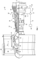
- FIG. 1 schematically illustrates a gas turbine engine 20 as one example of a machine or system in an aerospace environment as further described herein.
- the gas turbine engine 20 is depicted as a two-spool turbofan that generally incorporates a fan section 22, a compressor section 24, a combustor section 26 and a turbine section 28.
- the fan section 22 drives air along a bypass flow path B in a bypass duct to provide a majority of the thrust, while the compressor section 24 drives air along a core flow path C for compression and communication into the combustor section 26 then expansion through the turbine section 28.
- the exemplary engine 20 generally includes a low speed spool 30 and a high speed spool 32 mounted for rotation about an engine central longitudinal axis A relative to an engine static structure 36 via several bearing systems 38. It should be understood that various bearing systems 38 at various locations may alternatively or additionally be provided, and the location of bearing systems 38 may be varied as appropriate to the application.
- the low speed spool 30 generally includes an inner shaft 40 that interconnects a fan 42, a first (or low) pressure compressor 44 and a first (or low) pressure turbine 46.
- the inner shaft 40 is connected to the fan 42 through a speed change mechanism, which in exemplary gas turbine engine 20 is illustrated as a geared architecture 48 to drive the fan 42 at a lower speed than the low speed spool 30.
- the high speed spool 32 includes an outer shaft 50 that interconnects a second (or high) pressure compressor 52 and a second (or high) pressure turbine 54.
- a combustor 56 is arranged in exemplary gas turbine engine 20 between the high pressure compressor 52 and the high pressure turbine 54.
- a mid-turbine frame 58 of the engine static structure 36 is arranged generally between the high pressure turbine 54 and the low pressure turbine 46.
- the mid-turbine frame 58 further supports bearing systems 38 in the turbine section 28.
- the inner shaft 40 and the outer shaft 50 are concentric and rotate via bearing systems 38 about the engine central longitudinal axis A which is collinear with their longitudinal axes.
- the core airflow is compressed by the low pressure compressor 44 then the high pressure compressor 52, mixed and burned with fuel in the combustor 56, then expanded over the high pressure turbine 54 and low pressure turbine 46.
- the mid-turbine frame 58 includes airfoils 60 which are in the core airflow path C.
- the turbines 46, 54 rotationally drive the respective low speed spool 30 and high speed spool 32 in response to the expansion.
- gear system 48 may be located aft of combustor section 26 or even aft of turbine section 28, and fan section 22 may be positioned forward or aft of the location of gear system 48. In direct drive configurations, the gear system 48 can be omitted.
- the engine 20 in one example is a high-bypass geared aircraft engine.
- Low pressure turbine 46 pressure ratio is pressure measured prior to inlet of low pressure turbine 46 as related to the pressure at the outlet of the low pressure turbine 46 prior to an exhaust nozzle. A significant amount of thrust can be provided by the bypass flow B due to the high bypass ratio.
- the example low pressure turbine 46 can provide the driving power to rotate the fan section 22 and therefore the relationship between the number of turbine rotors 34 in the low pressure turbine 46 and the number of blades in the fan section 22 can establish increased power transfer efficiency.
- the disclosed example gas turbine engine 20 includes a control and health monitoring system 64 (generally referred to as system 64) utilized to monitor component performance and function.
- the system 64 includes a network 65, which is an example of a guided electromagnetic transmission network.
- the network 65 includes a controller 66 operable to communicate with nodes 68a, 68b through electromagnetic signals.
- the controller 66 may include various support interfaces and processing resources, such as input/output interfaces, processing systems, memory systems, communication interfaces, power management systems, and the like.
- the nodes 68a, 68b can be distributed throughout the gas turbine engine 20 or other such machine.
- Node 68a is an example of an actuator node that can drive one or more actuators/effectors of the gas turbine engine 20.
- Node 68b is an example of a sensor node that can interface with one or more sensors of the gas turbine engine 20.
- Nodes 68a, 68b can include processing support circuitry to transmit/receive electromagnetic signals between sensors or actuators and the controller 66.
- a coupler 67 can be configured as a splitter between a waveguide 70 coupled to the controller 66 and waveguides 71 and 72 configured to establish wireless communication with nodes 68a and 68b respectively.
- the coupler 67 can be a simple splitter or may include a repeater function to condition electromagnetic signals sent between the controller 66 and nodes 68a, 68b. In the example of FIG.
- a radio frequency-based repeater 76 is interposed between the coupler 67 and node 68b, where waveguide 72 is a first waveguide coupled to the coupler 67 and radio frequency-based repeater 76, and waveguide 73 is a second waveguide coupled to the radio frequency-based repeater 76 and node 68b.
- waveguides 70, 71, 72, 73 are configured to guide transmission of the radio frequencies (e.g., electromagnetic signals) between the controller 66 and one or more of the nodes 68a, 68b.
- the transmission media within waveguides 70-73 may include dielectric or gaseous material.
- the waveguides 70-73 can be hollow metal tubes.
- the waveguides 70-73 may be rigid or may include flexible material.
- the disclosed system 64 may be utilized to control and/or monitor any component function or characteristic of a turbomachine, aircraft component operation, and/or other machines.
- Prior control and diagnostic system architectures utilized in various applications may include a centralized system architecture in which the processing functions reside in an electronic control module. Actuator and sensor communications were accomplished through analog wiring for power, command, position feedback, sensor excitation and sensor signals. Cables and connections include shielding to minimize effects caused by electromagnetic interference (EMI). The use of analog wiring and the required connections can limit application and capability of such systems due to the ability to locate wires, connectors and electronics in harsh environments that experience extremes in temperature, pressure, and/or vibration. Exemplary embodiments can use radio frequencies guided by the waveguides 70-73 in a wireless architecture to provide both electromagnetic communication signals and power to the individual elements of the network 65.
- EMI electromagnetic interference
- Embodiments provide extension of a network where reduced signal-to-noise ratio (SNR) may compromise network performance by trading off data rates for an expansion of the number of nodes and distribution lines; thereby providing more nodes / sensors, with greater interconnectivity.
- SNR signal-to-noise ratio
- Embodiments can operate in the C-band of electromagnetic frequencies that can span 4 GHz to 8 GHz, for example.
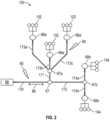
- a guided electromagnetic transmission network 100 is depicted as an example expansion of the network 65 of FIG. 1 .
- the guided electromagnetic transmission network 100 can include the controller 66 coupled to coupler 67 through waveguide 170.
- the coupler 67 is further coupled to coupler 67a through waveguide 171 and to coupler 67b through waveguide 172.
- Coupler 67a is further coupled to three nodes 68a through waveguides 173a, 173b, 173c in parallel.
- Each of the nodes 68a can interface or be combined with multiple actuators 102.
- Coupler 67b is also coupled to two nodes 68b through waveguides 174a, 174b in parallel.
- Each of the nodes 68b can interface or be combined with multiple sensors 104.
- Couplers 67, 67a, 67b can be splitters and/or can incorporate instances of the radio frequency-based repeater 76 of FIG. 1 . Further, one or more instances of the radio frequency-based repeater 76 can be installed at any of the waveguides 170, 171, 172, 173a-c, and/or 174a-b depending on the signal requirements of the guided electromagnetic transmission network 100.
- Nodes 68a, 68b can be associated with particular engine components, actuators or any other machine part from which information and communication is performed for monitoring and/or control purposes.
- the nodes 68a, 68b may contain a single or multiple electronic circuits or sensors configured to communicate over the guided electromagnetic transmission network 100.
- the controller 66 can send and receive power and data to and from the nodes 68a, 68b.
- the controller 66 may be located on equipment near other system components or located remotely as desired to meet application requirements.
- a transmission path (TP) between the controller 66 and nodes 68a, 68b can be used to send and receive data routed through the controller 66 from a control module or other components.
- the TP may utilize electromagnetic communication including radio frequency/microwave electromagnetic energy transferred through waveguides.
- the interface between the controller 66 and nodes 68a, 68b can transmit power and signals.
- the example nodes 68a, 68b may include radio-frequency identification devices along with processing, memory and/or the interfaces to connect to conventional sensors or actuators, such as solenoids or electro-hydraulic servo valves.
- the waveguides 170, 171, 172, 173a-c, and/or 174a-b can be shielded paths that support electromagnetic communication, including, for instance, radio frequency, microwaves, magnetic or optic waveguide transmission. Shielding can be provided such that electromagnetic energy or light interference 85 with electromagnetic signals 86 (shown schematically as arrows) are mitigated in the guided electromagnetic transmission network 100. Moreover, the shielding provides that the electromagnetic signals 86 are less likely to propagate into the environment outside the guided electromagnetic transmission network 100 and provide unauthorized access to information.
- guided electromagnetic radiation is in the range 1-100 GHz. Electromagnetic radiation can be more tightly arranged around specific carrier frequencies, such as 3-4.5 GHz, 24 GHz, 60 GHz, or 76-77 GHz as examples in the microwave spectrum. One or more carrier frequencies can transmit electric power, as well as communicate information, to multiple nodes 68a, 68b using various modulation and signaling techniques.
- the nodes 68a with actuators 102 may include control devices, such as a solenoid, switch or other physical actuation devices.
- Radio frequency identification, electromagnetic or optical devices implemented as the nodes 68b with sensors 104 can provide information indicative of a physical parameter, such as pressure, temperature, speed, proximity, vibration, identification, and/or other parameters used for identifying, monitoring or controlling component operation.
- Signals communicated in the guided electromagnetic transmission network 100 may employ techniques such as checksums, hash algorithms, error control algorithms and/or encryption to mitigate cyber security threats and interference.
- shielding in the guided electromagnetic transmission network 100 can be provided such that power and communication signals are shielded from outside interference, which may be caused by environmental electromagnetic or optic interference. Moreover, the shielding limits intentional interference 85 with communication at each component. Intentional interference 85 may take the form of unauthorized data capture, data insertion, general disruption and/or any other action that degrades system communication. Environmental sources of interference 85 may originate from noise generated from proximate electrical systems in other components or machinery along with electrostatic and magnetic fields, and/or any broadcast signals from transmitters or receivers. Additionally, environmental phenomena, such as cosmic radio frequency radiation, lightning or other atmospheric effects, could interfere with local electromagnetic communications.
- the system 64 provides for a reduction in cable and interconnecting systems to reduce cost and increases reliability by reducing the number of physical interconnections. Reductions in cable and connecting systems further provides for a reduction in weight while providing additional redundancy. Moreover, additional sensors can be added without the need for additional wiring and physical connections to the controller 66, which may provide for increased system accuracy and response. Embodiments can provide a "plug-n-play" approach to add a new node, potentially without a requalification of the entire system but only the new component; thereby greatly reducing qualification burdens.
- FIG. 3 is a schematic view of a waveguide system 200 in accordance with an embodiment of the disclosure.
- a first node 202 and a second node 212 are configured to establish a communication path to propagate at least one communication channel 206 and a radio frequency power transmission 208 through a waveguide 210 in a system, such as the gas turbine engine 20 of FIG. 1 .
- the first node 202 can include processing system elements, input/output, and communication interfaces to interface with the second node 212.
- the waveguide 210 can be an instance of the waveguides 70-73, 170, 171, 172, 173a-c, and/or 174a-b of FIGS. 1 and 2 .
- the first node 202 can be an instance of the controller 66 of FIGS. 1 and 2
- the second node 212 can be an instance of node 68a, 68b of FIGS. 1 and 2 , for example.
- the waveguide 210 can incorporate any combination of the design features as further described in reference to FIGS. 4-8 .
- a plurality of nodes can be connected by two or more instances of the waveguide 210, such as double-ridge waveguides 300, 400, 500, 600, 700 having first and second ridges as further described herein.
- FIG. 4 is a schematic view of a double-ridge waveguide 300 as one example of the waveguide 210 of FIG. 3 in accordance with an embodiment of the disclosure.
- the double-ridge waveguide 300 is an example that includes a metallic shell 302 surrounding a waveguide core 304 that forms a communication and radio frequency power transmission path in an aerospace environment.
- the waveguide core 304 in a cross-section of the double-ridge waveguide 300 can appear as an "H", where signals propagate through the interior portion of the waveguide core 304.
- the double-ridge waveguide 300 appears to have a consistent shape, the geometry of the double-ridge waveguide 300 can change externally and/or internally.
- the double-ridge waveguide 300 may include bends and junctions to support a one-to-many node connection architecture.
- the double-ridge waveguide 300 can be installed between the first node 202 and the second node 212 of FIG. 3 .
- the first node 202 can be configured to propagate at least one communication channel 206 and a radio frequency power transmission 208 through the waveguide core 304 to the second node 212 during operation of the system in the aerospace environment.
- the geometry of the waveguide core 304 can be sized based on the transmission frequency wavelengths.
- the wavelength can be computed as the speed of light divided by the frequency. For example, when operating in the C-Band with a frequency range of 4 GHz to 8 GHz, the resulting wavelengths can be computed and used to size the interior dimensions of the waveguide core 304.
- the double-ridge shape can provide more efficient transmission than a non-ridged configuration, which may require a larger core width and/or height.
- Sizing of the waveguide core 304 can also be determined with respect to a frequency gap and power differential between the communication channel 206 and a radio frequency power transmission 208, such that transmission of both signals can be accommodated within the waveguide core 304 as a multiplexed transmission.
- a metallization thickness (T1) of the metallic shell 302 surrounding a waveguide core 304 is equal to or greater than a skin depth to confine electromagnetic radiation within a structure formed by the double-ridge waveguide 300.
- the metallization thickness (T1) may be greater to provide more structural rigidity, for example, when longer separation distances exist between nodes 202, 212 and/or harsher environmental conditions exist.
- the double-ridge waveguide 400 of FIG. 5 can include a metallization thickness (T2) of a metallic shell 402 surrounding a waveguide core 404 that is thinner than the metallization thickness (T1) of double-ridge waveguide 300 of FIG. 4 .
- the waveguide core 404 may have substantially similar dimensions to the waveguide core 304 of FIG. 4 .
- the reduced metallization thickness (T2) of metallic shell 402 as compared to the metallization thickness (T1) of double-ridge waveguide 300 may be used to reduce weight.
- the metallization thickness (T2) can be less than the metallization thickness (T1), the metallization thickness (T2) is equal to or greater than a skin depth to confine electromagnetic radiation within a structure formed by the double-ridge waveguide 400.
- various metals and alloys can be used, such as titanium or aerospace aluminum alloy, for instance.
- FIG. 6 is a schematic view of a double-ridge waveguide 500 in accordance with an embodiment of the disclosure.
- the double-ridge waveguide 500 includes a metallic shell 502 surrounding a waveguide core 504 that forms a communication and radio frequency power transmission path in an aerospace environment.
- the metallic shell 502 can include a plurality of ribbed supports 510 distributed along an axis of transmission (A) between a first transmission volume 506 and a second transmission volume 508 of the waveguide core 504.
- the ribbed supports 510 can be incorporated in various embodiments as disclosed herein to enhance the structural integrity of a double-ridge waveguide, such as the double-ridge waveguide 500.
- FIG. 7 is a schematic view of a double-ridge waveguide 600 in accordance with an embodiment of the disclosure.
- the double-ridge waveguide 600 includes a metallic shell 602 surrounding a waveguide core 604 that forms a communication and radio frequency power transmission path in an aerospace environment.
- the waveguide core 604 can be made of a polymer material 605 through which at least one communication channel 206 and radio frequency power transmission 208 of FIG. 3 can be propagated.
- the polymer material 605 can be a high-dielectric, low-loss polymer, such as polyethene, Teflon, polyimide, or other such materials.
- a metallization thickness (T3) of the metallic shell 602 is equal to or greater than a skin depth to confine electromagnetic radiation within a structure formed by the double-ridge waveguide 600.
- the metallization thickness (T3) can be less than the metallization thickness (T2) of double-ridge waveguide 400 of FIG. 5 , as the polymer material 605 can provide more structural support than the waveguide core 404 (e.g., where waveguide core 404 is hollow or contains a fluid).
- FIG. 8 is a schematic view of a double-ridge waveguide 700 in accordance with an embodiment of the disclosure.
- the double-ridge waveguide 700 includes a metallic shell 702 surrounding a waveguide core 704 that forms a communication and radio frequency power transmission path in an aerospace environment.
- the waveguide core 704 can be made of a polymer material 705 through which at least one communication channel 206 and radio frequency power transmission 208 of FIG. 3 can be propagated.
- the polymer material 705 can be the same as polymer material 605 of FIG. 7 or have a different composition.
- a metallization thickness (T4) of the metallic shell 702 is equal to or greater than a skin depth to confine electromagnetic radiation within a structure formed by the double-ridge waveguide 700.
- the metallization thickness (T4) can be the same or less than the metallization thickness (T3) of double-ridge waveguide 600 of FIG. 7 .
- the double-ridge waveguide 700 also includes a polymer intensifier 707 having a different dielectric property than the polymer material 705.
- the polymer intensifier 707 can be formed between a first transmission volume 706 and a second transmission volume 708 of the waveguide core 704.
- the polymer intensifier 707 can be a polymer having a greater dielectric constant at a targeted frequency than the polymer material 705.
- the polymer intensifier 707 can be a ceramic or a composite material.
- the inclusion of the polymer intensifier 707 can result in a greater field concentration within the waveguide core 704. Properties of the polymer intensifier 707 can be selected to ensure that any bandwidth reduction can accommodate the frequencies selected for the communication channel 206 and radio frequency power transmission 208 of FIG. 3 .
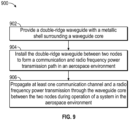
- FIG. 9 is a flow chart illustrating a method 900 of providing a waveguide system for transmitting communication and power in an aerospace environment, such as the gas turbine engine 20 of FIG. 1 in accordance with an embodiment.
- the method 900 of FIG. 9 is described in reference to FIGS. 1-9 and may be performed with an alternate order and include additional steps.
- a double-ridge waveguide with a metallic shell surrounding a waveguide core can be provided. Examples include any combination of features of the double-ridge waveguide 300, 400, 500, 600, 700. Each of the double-ridge waveguide 300, 400, 500, 600, 700 can include first and second ridges. Some embodiments can include additional ridges, e.g., a third ridge, a fourth ridge, etc.
- the double-ridge waveguide can be formed using a metallization process over a core material, such the polymer material 605 or the polymer material 705 with polymer intensifier 707.
- the double-ridge waveguide can be installed between two nodes, such as nodes 202, 212, to form a communication and radio frequency power transmission path in an aerospace environment.
- Each end of the double-ridge waveguide may be flush mounted to an interface of nodes 202, 212 such that the waveguide core aligns with a transmitter/receiver interface of the nodes 202, 212.
- the first node 202 can be a controller, such as controller 66
- the second node 212 can be configured to interface with at least one sensor 104 or at least one actuator 102 of the gas turbine engine 20.
- At block 906 at least one communication channel 206 and a radio frequency power transmission 208 can be propagated through the waveguide core between the two nodes 202, 212 during operation of a system in the aerospace environment.
- node 202 may broadcast commands to node 212 through communication channel 206, and node 212 may respond with status or data.
- Node 202 can also wirelessly provide power to the node 212 via radio frequency power transmission 208.
- the double-ridge waveguide configuration can provide a reduced size and weight profile as compared to other waveguide configurations.
Applications Claiming Priority (1)
| Application Number | Priority Date | Filing Date | Title |
|---|---|---|---|
| US17/497,612 US11929818B2 (en) | 2021-10-08 | 2021-10-08 | Waveguide system |
Publications (1)
| Publication Number | Publication Date |
|---|---|
| EP4164052A1 true EP4164052A1 (fr) | 2023-04-12 |
Family
ID=83689297
Family Applications (1)
| Application Number | Title | Priority Date | Filing Date |
|---|---|---|---|
| EP22200415.2A Pending EP4164052A1 (fr) | 2021-10-08 | 2022-10-07 | Système de guide d'ondes |
Country Status (2)
| Country | Link |
|---|---|
| US (1) | US11929818B2 (fr) |
| EP (1) | EP4164052A1 (fr) |
Citations (5)
| Publication number | Priority date | Publication date | Assignee | Title |
|---|---|---|---|---|
| KR101044959B1 (ko) * | 2010-03-26 | 2011-06-28 | (주)하이게인안테나 | 더블리지드 도파관을 이용한 삼중대역 스위처블 피더 시스템 |
| US20160254582A1 (en) * | 2015-02-27 | 2016-09-01 | Viasat, Inc. | Ridge loaded waveguide combiner/divider |
| US20170170571A1 (en) * | 2014-05-30 | 2017-06-15 | Mitsubishi Electric Corporation | Circularly polarized wave generator |
| US20170214110A1 (en) * | 2014-08-01 | 2017-07-27 | Bae Systems Plc | Dielectric loaded antenna for high temperature environment |
| US20200395649A1 (en) * | 2019-06-11 | 2020-12-17 | Intel Corporation | Low dispersion and low loss waveguides |
Family Cites Families (6)
| Publication number | Priority date | Publication date | Assignee | Title |
|---|---|---|---|---|
| US9748665B2 (en) | 2012-03-16 | 2017-08-29 | Raytheon Company | Ridged waveguide flared radiator array using electromagnetic bandgap material |
| EP3111075B1 (fr) | 2014-02-28 | 2020-11-25 | United Technologies Corporation | Réseau sans fil protégé |
| US9559428B1 (en) | 2015-08-25 | 2017-01-31 | Viasat, Inc. | Compact waveguide power combiner/divider for dual-polarized antenna elements |
| FR3051924B1 (fr) | 2016-05-30 | 2020-04-10 | Swissto 12 Sa | Guide d'ondes comprenant une couche conductrice epaisse |
| US10027004B2 (en) | 2016-07-28 | 2018-07-17 | The Boeing Company | Apparatus including a dielectric material disposed in a waveguide, wherein the dielectric permittivity is lower in a mode combiner portion than in a mode transition portion |
| US11329359B2 (en) | 2018-05-18 | 2022-05-10 | Intel Corporation | Dielectric waveguide including a dielectric material with cavities therein surrounded by a conductive coating forming a wall for the cavities |
-
2021
- 2021-10-08 US US17/497,612 patent/US11929818B2/en active Active
-
2022
- 2022-10-07 EP EP22200415.2A patent/EP4164052A1/fr active Pending
Patent Citations (5)
| Publication number | Priority date | Publication date | Assignee | Title |
|---|---|---|---|---|
| KR101044959B1 (ko) * | 2010-03-26 | 2011-06-28 | (주)하이게인안테나 | 더블리지드 도파관을 이용한 삼중대역 스위처블 피더 시스템 |
| US20170170571A1 (en) * | 2014-05-30 | 2017-06-15 | Mitsubishi Electric Corporation | Circularly polarized wave generator |
| US20170214110A1 (en) * | 2014-08-01 | 2017-07-27 | Bae Systems Plc | Dielectric loaded antenna for high temperature environment |
| US20160254582A1 (en) * | 2015-02-27 | 2016-09-01 | Viasat, Inc. | Ridge loaded waveguide combiner/divider |
| US20200395649A1 (en) * | 2019-06-11 | 2020-12-17 | Intel Corporation | Low dispersion and low loss waveguides |
Non-Patent Citations (1)
| Title |
|---|
| BOUSALAH FAYZA ET AL: "Design of Simple and Double Ridge Waveguide T-Coupler for Space Domain", ADVANCES IN APPLIED SCIENCES, vol. 4, no. 3, 1 January 2019 (2019-01-01), pages 78, XP093016227, ISSN: 2575-2065, DOI: 10.11648/j.aas.20190403.12 * |
Also Published As
| Publication number | Publication date |
|---|---|
| US11929818B2 (en) | 2024-03-12 |
| US20230112230A1 (en) | 2023-04-13 |
Similar Documents
| Publication | Publication Date | Title |
|---|---|---|
| US10484760B2 (en) | Electromagnetic communication from waveguide confinement | |
| EP3826192B1 (fr) | Répétiteur basé sur fréquence radio dans un système de guide d'ondes | |
| US11750236B2 (en) | Radio frequency waveguide communication in high temperature environments | |
| EP3978952A1 (fr) | Système de détection à micro-ondes à auto-référencement | |
| EP3979510A1 (fr) | Extraction de la puissance des n uds dans un système de guide d'ondes | |
| US20220190855A1 (en) | Radio frequency interface to sensor | |
| US11677831B2 (en) | Radio frequency waveguide system for mixed temperature environments | |
| EP3291363B1 (fr) | Communication électromagnétique par guide d'ondes | |
| EP4164052A1 (fr) | Système de guide d'ondes | |
| US11700567B2 (en) | Waveguide system with redundancy | |
| EP3291040B1 (fr) | Communication électromagnétique au travers de composants d'une machine | |
| US11652508B2 (en) | Radio frequency waveguide system nodes | |
| US11619567B2 (en) | Multi-mode microwave waveguide blade sensing system |
Legal Events
| Date | Code | Title | Description |
|---|---|---|---|
| PUAI | Public reference made under article 153(3) epc to a published international application that has entered the european phase |
Free format text: ORIGINAL CODE: 0009012 |
|
| STAA | Information on the status of an ep patent application or granted ep patent |
Free format text: STATUS: THE APPLICATION HAS BEEN PUBLISHED |
|
| AK | Designated contracting states |
Kind code of ref document: A1 Designated state(s): AL AT BE BG CH CY CZ DE DK EE ES FI FR GB GR HR HU IE IS IT LI LT LU LV MC ME MK MT NL NO PL PT RO RS SE SI SK SM TR |
|
| STAA | Information on the status of an ep patent application or granted ep patent |
Free format text: STATUS: REQUEST FOR EXAMINATION WAS MADE |
|
| RAP3 | Party data changed (applicant data changed or rights of an application transferred) |
Owner name: RTX CORPORATION |
|
| 17P | Request for examination filed |
Effective date: 20231012 |
|
| RBV | Designated contracting states (corrected) |
Designated state(s): AL AT BE BG CH CY CZ DE DK EE ES FI FR GB GR HR HU IE IS IT LI LT LU LV MC ME MK MT NL NO PL PT RO RS SE SI SK SM TR |