EP4164048A1 - Energiespeicherelement und herstellungsverfahren - Google Patents
Energiespeicherelement und herstellungsverfahren Download PDFInfo
- Publication number
- EP4164048A1 EP4164048A1 EP21200967.4A EP21200967A EP4164048A1 EP 4164048 A1 EP4164048 A1 EP 4164048A1 EP 21200967 A EP21200967 A EP 21200967A EP 4164048 A1 EP4164048 A1 EP 4164048A1
- Authority
- EP
- European Patent Office
- Prior art keywords
- free edge
- current collector
- strip
- anode
- cathode
- Prior art date
- Legal status (The legal status is an assumption and is not a legal conclusion. Google has not performed a legal analysis and makes no representation as to the accuracy of the status listed.)
- Pending
Links
- 238000004146 energy storage Methods 0.000 title claims abstract description 67
- 238000004519 manufacturing process Methods 0.000 title claims description 6
- 239000002131 composite material Substances 0.000 claims abstract description 65
- 238000007373 indentation Methods 0.000 claims abstract description 31
- 238000000034 method Methods 0.000 claims abstract description 26
- 239000007784 solid electrolyte Substances 0.000 claims abstract description 25
- 239000007772 electrode material Substances 0.000 claims abstract description 18
- 238000004804 winding Methods 0.000 claims description 46
- 229910052751 metal Inorganic materials 0.000 claims description 24
- 239000002184 metal Substances 0.000 claims description 24
- 239000007773 negative electrode material Substances 0.000 claims description 14
- 239000007774 positive electrode material Substances 0.000 claims description 14
- 238000003466 welding Methods 0.000 claims description 10
- 229910001416 lithium ion Inorganic materials 0.000 description 16
- PXHVJJICTQNCMI-UHFFFAOYSA-N Nickel Chemical compound [Ni] PXHVJJICTQNCMI-UHFFFAOYSA-N 0.000 description 13
- 229910052782 aluminium Inorganic materials 0.000 description 12
- XAGFODPZIPBFFR-UHFFFAOYSA-N aluminium Chemical compound [Al] XAGFODPZIPBFFR-UHFFFAOYSA-N 0.000 description 12
- 229910052744 lithium Inorganic materials 0.000 description 12
- WHXSMMKQMYFTQS-UHFFFAOYSA-N Lithium Chemical compound [Li] WHXSMMKQMYFTQS-UHFFFAOYSA-N 0.000 description 11
- 239000011149 active material Substances 0.000 description 9
- 239000000463 material Substances 0.000 description 9
- 239000004020 conductor Substances 0.000 description 8
- RYGMFSIKBFXOCR-UHFFFAOYSA-N Copper Chemical compound [Cu] RYGMFSIKBFXOCR-UHFFFAOYSA-N 0.000 description 7
- 239000011324 bead Substances 0.000 description 7
- 239000003792 electrolyte Substances 0.000 description 7
- -1 lithium hexafluorophosphate Chemical compound 0.000 description 6
- 229910052759 nickel Inorganic materials 0.000 description 6
- 239000002245 particle Substances 0.000 description 6
- OKTJSMMVPCPJKN-UHFFFAOYSA-N Carbon Chemical compound [C] OKTJSMMVPCPJKN-UHFFFAOYSA-N 0.000 description 5
- 239000010949 copper Substances 0.000 description 5
- 239000011883 electrode binding agent Substances 0.000 description 5
- 239000011888 foil Substances 0.000 description 5
- HBBGRARXTFLTSG-UHFFFAOYSA-N Lithium ion Chemical compound [Li+] HBBGRARXTFLTSG-UHFFFAOYSA-N 0.000 description 4
- 239000002033 PVDF binder Substances 0.000 description 4
- 230000015572 biosynthetic process Effects 0.000 description 4
- 229910052799 carbon Inorganic materials 0.000 description 4
- 238000005259 measurement Methods 0.000 description 4
- 229920000642 polymer Polymers 0.000 description 4
- 229920002981 polyvinylidene fluoride Polymers 0.000 description 4
- 239000010935 stainless steel Substances 0.000 description 4
- 229910001220 stainless steel Inorganic materials 0.000 description 4
- 229910000838 Al alloy Inorganic materials 0.000 description 3
- 229910013870 LiPF 6 Inorganic materials 0.000 description 3
- RTAQQCXQSZGOHL-UHFFFAOYSA-N Titanium Chemical compound [Ti] RTAQQCXQSZGOHL-UHFFFAOYSA-N 0.000 description 3
- 239000000654 additive Substances 0.000 description 3
- 239000004411 aluminium Substances 0.000 description 3
- 150000001875 compounds Chemical class 0.000 description 3
- 229910052802 copper Inorganic materials 0.000 description 3
- 150000002500 ions Chemical class 0.000 description 3
- 229910003473 lithium bis(trifluoromethanesulfonyl)imide Inorganic materials 0.000 description 3
- 229910003002 lithium salt Inorganic materials 0.000 description 3
- 159000000002 lithium salts Chemical class 0.000 description 3
- QSZMZKBZAYQGRS-UHFFFAOYSA-N lithium;bis(trifluoromethylsulfonyl)azanide Chemical compound [Li+].FC(F)(F)S(=O)(=O)[N-]S(=O)(=O)C(F)(F)F QSZMZKBZAYQGRS-UHFFFAOYSA-N 0.000 description 3
- 239000011159 matrix material Substances 0.000 description 3
- 239000002985 plastic film Substances 0.000 description 3
- 229920006255 plastic film Polymers 0.000 description 3
- 229910052710 silicon Inorganic materials 0.000 description 3
- 239000010703 silicon Substances 0.000 description 3
- 210000002023 somite Anatomy 0.000 description 3
- 229920002134 Carboxymethyl cellulose Polymers 0.000 description 2
- 229910000881 Cu alloy Inorganic materials 0.000 description 2
- 229910013063 LiBF 4 Inorganic materials 0.000 description 2
- 229910012851 LiCoO 2 Inorganic materials 0.000 description 2
- 229910010707 LiFePO 4 Inorganic materials 0.000 description 2
- 239000002202 Polyethylene glycol Substances 0.000 description 2
- XUIMIQQOPSSXEZ-UHFFFAOYSA-N Silicon Chemical compound [Si] XUIMIQQOPSSXEZ-UHFFFAOYSA-N 0.000 description 2
- 229910000831 Steel Inorganic materials 0.000 description 2
- ATJFFYVFTNAWJD-UHFFFAOYSA-N Tin Chemical compound [Sn] ATJFFYVFTNAWJD-UHFFFAOYSA-N 0.000 description 2
- 229910052787 antimony Inorganic materials 0.000 description 2
- WATWJIUSRGPENY-UHFFFAOYSA-N antimony atom Chemical compound [Sb] WATWJIUSRGPENY-UHFFFAOYSA-N 0.000 description 2
- 239000001768 carboxy methyl cellulose Substances 0.000 description 2
- 235000010948 carboxy methyl cellulose Nutrition 0.000 description 2
- 239000008112 carboxymethyl-cellulose Substances 0.000 description 2
- 230000006835 compression Effects 0.000 description 2
- 238000007906 compression Methods 0.000 description 2
- 230000000694 effects Effects 0.000 description 2
- 238000012983 electrochemical energy storage Methods 0.000 description 2
- 238000005516 engineering process Methods 0.000 description 2
- 229910001496 lithium tetrafluoroborate Inorganic materials 0.000 description 2
- VDVLPSWVDYJFRW-UHFFFAOYSA-N lithium;bis(fluorosulfonyl)azanide Chemical compound [Li+].FS(=O)(=O)[N-]S(F)(=O)=O VDVLPSWVDYJFRW-UHFFFAOYSA-N 0.000 description 2
- 239000011572 manganese Substances 0.000 description 2
- 150000002739 metals Chemical class 0.000 description 2
- 239000000203 mixture Substances 0.000 description 2
- 239000003960 organic solvent Substances 0.000 description 2
- 229920003229 poly(methyl methacrylate) Polymers 0.000 description 2
- 229920001223 polyethylene glycol Polymers 0.000 description 2
- 239000004926 polymethyl methacrylate Substances 0.000 description 2
- 230000000284 resting effect Effects 0.000 description 2
- 150000003839 salts Chemical class 0.000 description 2
- 239000010959 steel Substances 0.000 description 2
- 239000000126 substance Substances 0.000 description 2
- 229910052718 tin Inorganic materials 0.000 description 2
- 239000010936 titanium Substances 0.000 description 2
- BTBUEUYNUDRHOZ-UHFFFAOYSA-N Borate Chemical compound [O-]B([O-])[O-] BTBUEUYNUDRHOZ-UHFFFAOYSA-N 0.000 description 1
- 241000219504 Caryophyllales Species 0.000 description 1
- 229910015643 LiMn 2 O 4 Inorganic materials 0.000 description 1
- 229910013716 LiNi Inorganic materials 0.000 description 1
- 229910000990 Ni alloy Inorganic materials 0.000 description 1
- VYPSYNLAJGMNEJ-UHFFFAOYSA-N Silicium dioxide Chemical compound O=[Si]=O VYPSYNLAJGMNEJ-UHFFFAOYSA-N 0.000 description 1
- 229920002125 Sokalan® Polymers 0.000 description 1
- 229910001069 Ti alloy Inorganic materials 0.000 description 1
- SFKQQYOXXWIJSA-UHFFFAOYSA-N [Li+].[O--].[O--].[O--].[O--].[O--].[Al+3].[Mn++].[Co++].[Ni++] Chemical compound [Li+].[O--].[O--].[O--].[O--].[O--].[Al+3].[Mn++].[Co++].[Ni++] SFKQQYOXXWIJSA-UHFFFAOYSA-N 0.000 description 1
- KLARSDUHONHPRF-UHFFFAOYSA-N [Li].[Mn] Chemical compound [Li].[Mn] KLARSDUHONHPRF-UHFFFAOYSA-N 0.000 description 1
- 239000002253 acid Substances 0.000 description 1
- 230000000996 additive effect Effects 0.000 description 1
- 238000004026 adhesive bonding Methods 0.000 description 1
- 239000002390 adhesive tape Substances 0.000 description 1
- 229910045601 alloy Inorganic materials 0.000 description 1
- 239000000956 alloy Substances 0.000 description 1
- NDPGDHBNXZOBJS-UHFFFAOYSA-N aluminum lithium cobalt(2+) nickel(2+) oxygen(2-) Chemical compound [Li+].[O--].[O--].[O--].[O--].[Al+3].[Co++].[Ni++] NDPGDHBNXZOBJS-UHFFFAOYSA-N 0.000 description 1
- OJIJEKBXJYRIBZ-UHFFFAOYSA-N cadmium nickel Chemical group [Ni].[Cd] OJIJEKBXJYRIBZ-UHFFFAOYSA-N 0.000 description 1
- 239000006229 carbon black Substances 0.000 description 1
- 239000002388 carbon-based active material Substances 0.000 description 1
- 239000003575 carbonaceous material Substances 0.000 description 1
- BVKZGUZCCUSVTD-UHFFFAOYSA-N carbonic acid Chemical compound OC(O)=O BVKZGUZCCUSVTD-UHFFFAOYSA-N 0.000 description 1
- 238000006243 chemical reaction Methods 0.000 description 1
- 239000006258 conductive agent Substances 0.000 description 1
- 239000011889 copper foil Substances 0.000 description 1
- 150000004292 cyclic ethers Chemical class 0.000 description 1
- 230000001419 dependent effect Effects 0.000 description 1
- 238000007599 discharging Methods 0.000 description 1
- 239000011262 electrochemically active material Substances 0.000 description 1
- 238000003411 electrode reaction Methods 0.000 description 1
- 238000004049 embossing Methods 0.000 description 1
- 150000002148 esters Chemical class 0.000 description 1
- 150000002170 ethers Chemical class 0.000 description 1
- 239000004744 fabric Substances 0.000 description 1
- 239000010439 graphite Substances 0.000 description 1
- 229910002804 graphite Inorganic materials 0.000 description 1
- 238000009830 intercalation Methods 0.000 description 1
- 238000003475 lamination Methods 0.000 description 1
- 239000007788 liquid Substances 0.000 description 1
- 229910000625 lithium cobalt oxide Inorganic materials 0.000 description 1
- GELKBWJHTRAYNV-UHFFFAOYSA-K lithium iron phosphate Chemical compound [Li+].[Fe+2].[O-]P([O-])([O-])=O GELKBWJHTRAYNV-UHFFFAOYSA-K 0.000 description 1
- 229910021450 lithium metal oxide Inorganic materials 0.000 description 1
- CJYZTOPVWURGAI-UHFFFAOYSA-N lithium;manganese;manganese(3+);oxygen(2-) Chemical compound [Li+].[O-2].[O-2].[O-2].[O-2].[Mn].[Mn+3] CJYZTOPVWURGAI-UHFFFAOYSA-N 0.000 description 1
- VGYDTVNNDKLMHX-UHFFFAOYSA-N lithium;manganese;nickel;oxocobalt Chemical compound [Li].[Mn].[Ni].[Co]=O VGYDTVNNDKLMHX-UHFFFAOYSA-N 0.000 description 1
- BFZPBUKRYWOWDV-UHFFFAOYSA-N lithium;oxido(oxo)cobalt Chemical compound [Li+].[O-][Co]=O BFZPBUKRYWOWDV-UHFFFAOYSA-N 0.000 description 1
- 229910052987 metal hydride Inorganic materials 0.000 description 1
- 239000006262 metallic foam Substances 0.000 description 1
- 229910001317 nickel manganese cobalt oxide (NMC) Inorganic materials 0.000 description 1
- 150000002825 nitriles Chemical class 0.000 description 1
- 239000004745 nonwoven fabric Substances 0.000 description 1
- 150000005677 organic carbonates Chemical class 0.000 description 1
- 230000003647 oxidation Effects 0.000 description 1
- 238000007254 oxidation reaction Methods 0.000 description 1
- 150000003013 phosphoric acid derivatives Chemical class 0.000 description 1
- 239000004033 plastic Substances 0.000 description 1
- 229920003023 plastic Polymers 0.000 description 1
- 229920001643 poly(ether ketone) Polymers 0.000 description 1
- 229920000058 polyacrylate Polymers 0.000 description 1
- 229920000098 polyolefin Polymers 0.000 description 1
- 239000000843 powder Substances 0.000 description 1
- 238000003825 pressing Methods 0.000 description 1
- 238000006479 redox reaction Methods 0.000 description 1
- 230000001105 regulatory effect Effects 0.000 description 1
- 230000002441 reversible effect Effects 0.000 description 1
- 229910052814 silicon oxide Inorganic materials 0.000 description 1
- 229910052596 spinel Inorganic materials 0.000 description 1
- 239000011029 spinel Substances 0.000 description 1
- 239000000758 substrate Substances 0.000 description 1
- 125000005463 sulfonylimide group Chemical group 0.000 description 1
- 229910052719 titanium Inorganic materials 0.000 description 1
- XPDWGBQVDMORPB-UHFFFAOYSA-N trifluoromethane acid Natural products FC(F)F XPDWGBQVDMORPB-UHFFFAOYSA-N 0.000 description 1
Images


Classifications
-
- H—ELECTRICITY
- H01—ELECTRIC ELEMENTS
- H01M—PROCESSES OR MEANS, e.g. BATTERIES, FOR THE DIRECT CONVERSION OF CHEMICAL ENERGY INTO ELECTRICAL ENERGY
- H01M50/00—Constructional details or processes of manufacture of the non-active parts of electrochemical cells other than fuel cells, e.g. hybrid cells
- H01M50/50—Current conducting connections for cells or batteries
- H01M50/531—Electrode connections inside a battery casing
- H01M50/533—Electrode connections inside a battery casing characterised by the shape of the leads or tabs
-
- H—ELECTRICITY
- H01—ELECTRIC ELEMENTS
- H01M—PROCESSES OR MEANS, e.g. BATTERIES, FOR THE DIRECT CONVERSION OF CHEMICAL ENERGY INTO ELECTRICAL ENERGY
- H01M50/00—Constructional details or processes of manufacture of the non-active parts of electrochemical cells other than fuel cells, e.g. hybrid cells
- H01M50/50—Current conducting connections for cells or batteries
- H01M50/531—Electrode connections inside a battery casing
- H01M50/538—Connection of several leads or tabs of wound or folded electrode stacks
-
- H—ELECTRICITY
- H01—ELECTRIC ELEMENTS
- H01M—PROCESSES OR MEANS, e.g. BATTERIES, FOR THE DIRECT CONVERSION OF CHEMICAL ENERGY INTO ELECTRICAL ENERGY
- H01M50/00—Constructional details or processes of manufacture of the non-active parts of electrochemical cells other than fuel cells, e.g. hybrid cells
- H01M50/50—Current conducting connections for cells or batteries
- H01M50/531—Electrode connections inside a battery casing
- H01M50/54—Connection of several leads or tabs of plate-like electrode stacks, e.g. electrode pole straps or bridges
-
- Y—GENERAL TAGGING OF NEW TECHNOLOGICAL DEVELOPMENTS; GENERAL TAGGING OF CROSS-SECTIONAL TECHNOLOGIES SPANNING OVER SEVERAL SECTIONS OF THE IPC; TECHNICAL SUBJECTS COVERED BY FORMER USPC CROSS-REFERENCE ART COLLECTIONS [XRACs] AND DIGESTS
- Y02—TECHNOLOGIES OR APPLICATIONS FOR MITIGATION OR ADAPTATION AGAINST CLIMATE CHANGE
- Y02E—REDUCTION OF GREENHOUSE GAS [GHG] EMISSIONS, RELATED TO ENERGY GENERATION, TRANSMISSION OR DISTRIBUTION
- Y02E60/00—Enabling technologies; Technologies with a potential or indirect contribution to GHG emissions mitigation
- Y02E60/10—Energy storage using batteries
-
- Y—GENERAL TAGGING OF NEW TECHNOLOGICAL DEVELOPMENTS; GENERAL TAGGING OF CROSS-SECTIONAL TECHNOLOGIES SPANNING OVER SEVERAL SECTIONS OF THE IPC; TECHNICAL SUBJECTS COVERED BY FORMER USPC CROSS-REFERENCE ART COLLECTIONS [XRACs] AND DIGESTS
- Y02—TECHNOLOGIES OR APPLICATIONS FOR MITIGATION OR ADAPTATION AGAINST CLIMATE CHANGE
- Y02P—CLIMATE CHANGE MITIGATION TECHNOLOGIES IN THE PRODUCTION OR PROCESSING OF GOODS
- Y02P70/00—Climate change mitigation technologies in the production process for final industrial or consumer products
- Y02P70/50—Manufacturing or production processes characterised by the final manufactured product
Definitions
- the invention relates to an energy storage element that is suitable for providing very high currents, and to a method for producing such an energy storage element.
- Electrochemical energy storage elements are capable of converting stored chemical energy into electrical energy through a redox reaction.
- the simplest form of electrochemical energy storage element is the electrochemical cell. It comprises a positive and a negative electrode separated from each other by a separator. During a discharge, electrons are released at the negative electrode as a result of an oxidation process. This results in an electron stream that can be tapped off by an external electrical consumer for which the electrochemical cell serves as an energy supplier. At the same time, an ion current corresponding to the electrode reaction occurs within the cell. This flow of ions traverses the separator and is made possible by an ion-conducting electrolyte.
- the discharge is reversible, i.e. if there is the possibility of reversing the conversion of chemical energy into electrical energy during the discharge and charging the cell again, this is referred to as a secondary cell.
- Secondary lithium-ion cells are used today as energy storage elements for many applications, since they can provide high currents and are characterized by a comparatively high energy density. They are based on the use of lithium, which can migrate back and forth between the electrodes of the cell in the form of ions.
- the negative electrode and the positive electrode of a lithium-ion cell are usually formed by what are known as composite electrodes, which also include electrochemically inactive components in addition to electrochemically active components.
- electrochemically active components for secondary lithium-ion cells.
- active materials for the negative electrode
- carbon-based particles such as graphitic carbon.
- lithium cobalt oxide (LiCoO 2 ), lithium manganese oxide (LiMn 2 O 4 ), lithium iron phosphate (LiFePO 4 ) or derivatives thereof can be used as active materials for the positive electrode.
- the electrochemically active materials are usually contained in the electrodes in particle form.
- the composite electrodes generally include a flat and/or strip-shaped current collector, for example a metallic foil, which serves as a carrier for the respective active material.
- the current collector for the negative electrode can be formed of, for example, copper or nickel
- the current collector for the positive electrode can be formed of, for example, aluminum.
- the electrodes can comprise an electrode binder (e.g. polyvinylidene fluoride (PVDF) or another polymer, for example carboxymethyl cellulose), conductivity-improving additives and other additives as electrochemically inactive components.
- PVDF polyvinylidene fluoride
- the electrode binder ensures the mechanical stability of the electrodes and often also the adhesion of the active material to the current collectors.
- lithium-ion cells usually include solutions of lithium salts such as lithium hexafluorophosphate (LiPF 6 ) in organic solvents (e.g. ethers and esters of carbonic acid).
- lithium salts such as lithium hexafluorophosphate (LiPF 6 ) in organic solvents (e.g. ethers and esters of carbonic acid).
- the composite electrodes are combined with one or more separators to form a composite body.
- the electrodes and separators are usually connected to one another under pressure, optionally also by lamination or by gluing.
- the basic functionality of the cell can then be established by impregnating the composite with the electrolyte.
- the composite body is formed in the form of a coil or fabricated into a coil.
- the composite body can also be a stack of electrodes.
- Lithium-ion cells with the highest possible energy density are required for applications in the automotive sector, for e-bikes or for other applications with high energy requirements such as in tools, which are also able to withstand high currents during charging and discharging .
- Cylindrical round cells are described in which a composite body is formed from strip-shaped electrodes and is in the form of a coil.
- the electrodes each have current collectors loaded with electrode material.
- Oppositely polarized electrodes are arranged offset to one another within the composite body, so that longitudinal edges of the current collectors of the positive electrodes emerge from the winding on one side and longitudinal edges of the current collectors of the negative electrodes on another side.
- the cell has contact plates which are seated on the end faces of the winding and are connected to the longitudinal edges of the current collectors by welding. This makes it possible to electrically contact the current collectors and thus also the associated electrodes over their entire length. This significantly lowers the internal resistance within the described cell. As a result, the occurrence of large currents can be intercepted much better and heat can also be better dissipated from the winding.
- a potential problem here is that the edges of the current collectors are often compressed in an uncontrolled manner when the contact plates are applied, which can result in undefined folds. A large-area, form-fitting contact between the end faces and the contact plates is made more difficult as a result. In addition, there is an increased risk of fine or short circuits on the end face, for example as a result of damage to the separator arranged between the electrodes.
- a targeted pre-deformation of the edges of current collectors is from the U.S. 2018/0190962 A1 and from the JP 2015-149499 A known.
- the present invention was based on the object of providing energy storage elements which are characterized by a composite body made of electrodes and optionally one or more separators, which can be contacted more easily by means of said contact plates.
- the energy storage element according to the invention is therefore characterized in particular by the fact that it has current collectors whose free edge strips have been subjected to a forming process. This enables a better connection of the current collectors to the contact plates, which in turn can reduce the thermal connection of the electrodes to the housing and the internal resistance of the cell. In addition, the risk of an internal short circuit is also reduced, since the U- or V-shaped cross section enables the edge strip to be folded in a very defined manner when a contact plate is pressed on. The uncontrolled compression mentioned at the beginning cannot occur in this way.
- both the edge strip of the anode current collector and the edge strip of the cathode current collector have the U-shaped or V-shaped cross section.
- U-shaped and V-shaped should not be construed as implying that the cross section has a perfect U or V shape.
- a V-shaped cross section is very pointed, i.e. the legs of the V enclose a very small angle, or the U is deformed in the area of its opening.
- the edge strip or strips do not necessarily have the U-shaped or V-shaped cross section in their entirety. Rather, it is preferred that only a portion of the edge strip or strips is subjected to the forming process.
- the edge strip or strips thus comprise at least one area that is not deformed by the forming process. This preferably extends along the elongated depression or indentation or along the elongated elevation corresponding to the depression or indentation.
- the composite body preferably comprises a strip-shaped separator or two strip-shaped separators which each have a first and a second longitudinal edge and two end pieces.
- the contact plates preferably sit flat on the two end faces.
- a number of particular advantages are associated with the cylindrical embodiment of the energy storage element according to the invention. It is known from the prior art that when producing cylindrical windings from electrodes, a so-called “telescoping effect” can occur due to imprecise winding of the electrode edges, which can result in uneven end faces of the winding. As a result, there are dimensional, mechanical and welding problems. With according to the Invention reshaped edge strips, this effect can be avoided.
- the edge strip with the U-shaped or the V-shaped cross-section can offer guidance in the case of windings, so that inaccuracies in the production of the winding are counteracted.
- the cover component preferably has a circular circumference and is arranged in the circular opening of the cup-shaped housing part in such a way that the edge along a circumferential contact zone rests against the inside of the cup-shaped housing part, the edge of the cover component being in contact with the cup-shaped housing part via a circumferential weld is connected.
- the two housing parts preferably have the same polarity, ie are electrically coupled to either a positive or a negative electrode.
- the housing also includes a pole bushing, which is used for making electrical contact with the electrode that is not electrically connected to the housing.
- an electrically insulating seal is pulled onto the edge of the cover component, which seal electrically separates the cover component from the cup-shaped housing part.
- the housing is usually sealed with a crimp closure.
- the height of energy storage elements designed as a cylindrical round cell is preferably in the range from 50 mm to 150 mm.
- the diameter of the cylindrical round cells is preferably in the range from 15 mm to 60 mm. Cylindrical round cells with these form factors are particularly suitable for powering electric drives in motor vehicles.
- the contact sheets preferably have a circular basic shape.
- the continuous metal layer is a closed layer that completely covers the first end face.
- the adjacent turns formed during manufacture of the coil have different diameters. Inside turns always have a smaller diameter than outside ones, or in other words, the diameter of the coil increases with each turn of the coil towards the outside.
- the features a. to c. particularly preferably even the features a. to d., are realized in combination with one another.
- oppositely polarized electrodes are always separated from one another by a separator or solid electrolyte layer.
- the prismatic housing is preferably composed of a cup-shaped housing part with an opening at the end and a cover component.
- the bottom of the cup-shaped housing part and the cover component preferably have a polygonal, particularly preferably a rectangular, base area.
- the shape of the terminal opening of the cup-shaped housing part corresponds to the shape of the base and the lid component.
- the housing comprises a plurality of, preferably four, rectangular side parts which connect the base and the cover component to one another.
- the separator layers can be formed by a plurality of separators, each of which is arranged between adjacent electrodes. However, it is also possible for a band-shaped separator to separate the electrodes of the stack from one another. In the case of several separators between the anodes and cathodes, the separators preferably also have a polygonal, in particular rectangular, base area.
- the contact sheets preferably have a rectangular basic shape.
- Feature a refers in particular to the described embodiment of the energy storage element according to the invention as a cylindrical round cell.
- the energy storage element preferably comprises exactly one electrochemical cell.
- feature b refers in particular to the described prismatic embodiment of the energy storage element according to the invention.
- the energy storage element can also comprise more than one electrochemical cell.
- all electrode materials known for secondary lithium-ion cells can be used for the electrodes of the energy storage element.
- Particles based on carbon such as graphitic carbon, or non-graphitic carbon materials capable of intercalating lithium, preferably also in particle form, can be used as active materials in the negative electrodes.
- lithium titanate (Li 4 Ti 5 O 12 ) or a derivative thereof can also be contained in the negative electrode, preferably also in particle form.
- the negative electrode can contain as active material at least one material from the group consisting of silicon, aluminum, tin, antimony or a compound or alloy of these materials which can reversibly intercalate and deintercalate lithium, for example silicon oxide, optionally in combination with carbon-based active materials .
- Tin, aluminum, antimony and silicon able to form intermetallic phases with lithium.
- the capacity for absorbing lithium is many times greater than that of graphite or comparable materials, particularly in the case of silicon.
- thin anodes made of metallic lithium can also be used.
- lithium nickel manganese cobalt oxide (NMC) with the molecular formula Li-Ni x Mn y Co z O 2 (where x + y + z is typically 1)
- lithium manganese spinel (LMO) with the molecular formula LiMn 2 O 4
- lithium nickel cobalt aluminum oxide (NCA ) with the molecular formula LiNi x Co y Al z O 2 (where x + y + z is typically 1).
- lithium nickel manganese cobalt aluminum oxide with the molecular formula Li 1.11 (Ni 0.40 Mn 0.39 Co 0.16 Al 0.05 ) 0.89 O 2 or Li 1+x MO compounds and/or mixtures of the materials mentioned can be used.
- the cathodic active materials are also preferably used in particulate form.
- the electrodes of an energy storage element according to the invention preferably contain an electrode binder and/or an additive to improve the electrical conductivity.
- the active materials are preferably embedded in a matrix of the electrode binder, with neighboring particles in the matrix preferably being in direct contact with one another.
- Conductors serve to increase the electrical conductivity of the electrodes.
- Customary electrode binders are based, for example, on polyvinylidene fluoride (PVDF), polyacrylate or carboxymethyl cellulose.
- Common conductive agents are carbon black and metal powder.
- the energy storage element according to the invention preferably comprises an electrolyte, in the case of a lithium-ion cell in particular an electrolyte based on at least one lithium salt such as lithium hexafluorophosphate (LiPF 6 ), which is dissolved in an organic solvent (e.g. in a mixture of organic carbonates or a cyclic ether such as THF or a nitrile).
- an organic solvent e.g. in a mixture of organic carbonates or a cyclic ether such as THF or a nitrile.
- lithium tetrafluoroborate LiBF 4
- LiTFSI lithium bis(trifluoromethanesulfonyl)imide
- LiFSI lithium bis(fluorosulfonyl)imide
- LiBOB lithium bis(oxalato)borate
- the nominal capacity of a lithium-ion-based energy storage element according to the invention designed as a cylindrical round cell is preferably up to 90,000 mAh.
- the energy storage element is preferred in one embodiment as a lithium-ion cell a nominal capacity in the range of 1500 mAh to 7000 mAh, more preferably in the range of 3000 to 5500 mAh.
- the cell in one embodiment as a lithium-ion cell preferably has a nominal capacity in the range from 1000 mAh to 5000 mAh, particularly preferably in the range from 2000 to 4000 mAh.
- the separator or separators are preferably formed from electrically insulating plastic films. It is preferred that the separators can be penetrated by the electrolyte.
- the plastic films used can have micropores, for example.
- the film can consist, for example, of a polyolefin or of a polyether ketone. Fleeces and fabrics made from plastic materials or other electrically insulating flat structures can also be used as separators. Separators are preferably used which have a thickness in the range from 5 ⁇ m to 50 ⁇ m.
- the separator or separators of the composite can also be one or more layers of a solid electrolyte.
- the solid electrolyte is, for example, a polymer solid electrolyte based on a polymer-conductive salt complex, which is present in a single phase without any liquid component.
- a polymer solid electrolyte can have polyacrylic acid (PAA), polyethylene glycol (PEG) or polymethyl methacrylate (PMMA) as the polymer matrix.
- Lithium conductive salts such as lithium bis-(trifluoromethane)sulfonylimide (LiTFSI), lithium hexafluorophosphate (LiPF 6 ) and lithium tetrafluoroborate (LiBF 4 ) can be present dissolved in these.
- the strip-shaped anode, the strip-shaped cathode and the strip-shaped separator or separators are preferably wound up in a spiral shape.
- the strip-shaped electrodes are fed together with the strip-shaped separator or separators to a winding device and are preferably wound up spirally in this device around a winding axis.
- the electrodes and the separator are wound onto a cylindrical or hollow-cylindrical winding core, which sits on a winding mandrel and remains in the winding after winding.
- the winding jacket can be formed, for example, by a plastic film or an adhesive tape. It is also possible for the winding jacket to be formed by one or more separator turns.
- the current collectors of the energy storage element serve to electrically contact electrochemically active components contained in the respective electrode material over as large an area as possible.
- the current collectors preferably consist of a metal or are at least metallized on the surface.
- copper or nickel for example, or also other electrically conductive materials, in particular copper and nickel alloys or metals coated with nickel, are suitable as the metal for the anode current collector.
- stainless steel is also an option.
- aluminum or other electrically conductive materials, including aluminum alloys are particularly suitable as the metal for the cathode current collector.
- the anode current collector and/or the cathode current collector is preferably a metal foil with a thickness in the range of 4 ⁇ m to 30 ⁇ m, in the case of the described configuration of the energy storage element as a cylindrical round cell it is a strip-shaped metal foil with a thickness in the range of 4 ⁇ m up to 30 ⁇ m.
- strip-shaped substrates such as metallic ones can also be used as current collectors or metallized nonwovens or open-pored metallic foams or expanded metals can be used.
- the longitudinal edges of the separator or separators form the end faces of the composite body designed as a coil.
- edges of the separator or separators form the sides of the stack from which the free edge strips of the current collectors emerge.
- the free edge strips of the current collectors emerging from the end faces of the coil or sides of the stack do not protrude by more than 5500 ⁇ m, preferably no more than 4000 ⁇ m, from the end faces or sides.
- the free edge strip of the anode current collector protrudes from the side of the stack or the face of the coil by no more than 3000 ⁇ m, particularly preferably no more than 2000 ⁇ m.
- the free edge strip of the cathode current collector particularly preferably protrudes from the side of the stack or the face of the coil by no more than 4000 ⁇ m, particularly preferably no more than 3000 ⁇ m.
- the first contact plate is preferably electrically connected to the anode current collector. It is particularly preferably connected directly to the free edge strip of the anode current collector by welding.
- the first contact sheet can also be mechanically connected to the free edge strip of the anode current collector, for example by a press connection or a clamp connection or a spring connection.
- the contact plate is either electrically connected to the housing or to a contact pole that is routed through the housing and is electrically insulated from the housing.
- the electrical contact can be realized by direct welding or a mechanical connection. If necessary, the electrical connection can also be made via a separate electrical conductor.
- features a. and b. and d. are realized in combination with each other.
- the features a. and b. and d. in combination with one of the features c. or e. or the features f. and g realized. All features a. to g. implemented in combination.
- the largest possible covering of the end face is important for the thermal management of the grounded energy storage element.
- the larger the cover the more likely it is possible to contact the first edge of the anode current collector over its entire length if possible. Heat generated in the composite body can thus be dissipated easily via the contact sheet.
- the at least one opening in the contact sheet can be expedient, for example, in order to be able to saturate the composite body with an electrolyte.
- the second contact plate is preferably electrically connected to the cathode current collector. It is particularly preferably connected directly to the free edge strip of the cathode current collector by welding.
- the second contact sheet can also be mechanically connected to the free edge strip of the cathode current collector, for example by a press connection, a spring connection or a clamp connection.
- the contact plate is either electrically connected to the housing or to a contact pole that is routed through the housing and is electrically insulated from the housing.
- the electrical contact can be made directly by welding or by a mechanical connection be realised. If necessary, the electrical connection can also be made via a separate electrical conductor.
- the features a. and b. and d. are realized in combination with each other.
- the features a. and b. and d. in combination with one of the features c. or e. or the features f. and g realized.
- all features a are particularly preferred. to g. implemented in combination.
- connection or welding of the free edge strip of the cathode current collector to the second contact plate is preferably implemented analogously to the connection of the free edge strip of the anode current collector described above, ie particularly preferably via a weld in the area of the bead.
- the second contact plate is welded directly to the bottom of the cup-shaped housing part or to a part of the bottom.
- the second contact plate is connected to the base of the cup-shaped housing part via a separate current conductor.
- the separate current conductor is welded both to the base of the cup-shaped housing part and to the second contact plate.
- the separate current conductor is preferably made of aluminum or an aluminum alloy.
- the free edge strip can be welded to the bottom of the cup-shaped housing part, for example by means of a laser.
- the bottom of the cup-shaped housing part serves as a second contact plate.
- the first contact plate serves as a cover component, ie serves as part of the housing.
- the process is characterized in particular by the following step: H.
- at least one edge strip is subjected to a forming process, as a result of which it has a U-shaped or V-shaped cross section and thus an elongated depression or indentation on one side and an elongated elevation corresponding to the depression on the other side.
- This variant of the method is used to produce an energy storage element in a cylindrical embodiment.
- This variant of the method is used to produce an energy storage element in a prismatic embodiment.
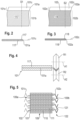
- FIG. 1 1 illustrates the result of a contact plate 201 being pressed onto an overhanging edge 202 of a current collector which emerges from one side of a composite body 203 made up of negative and positive electrodes and separators lying between them (not shown in the drawing).
- the edge 202 of the current collector was compressed in an uncontrolled manner. The compression in turn partially results in undefined folds, as can be seen particularly well in the right-hand area of edge 202 .
- a large-area, form-fitting contact between the current collector edge 202 and the contact plate 201 is made more difficult as a result.
- the current collector 101 is preferably an aluminum foil.
- the strip-shaped current collector 101a comprises a main region 101b loaded with the electrode material 117 and a strip-shaped edge strip 101c which is free of electrode material.
- FIG. 3 12 shows a current collector 102a, to which a layer of a negative electrode material 118 is applied on both sides, on the one hand in a plan view from above and on the other hand in a cross-sectional representation (section along S2).
- the current collector 101 is preferably a copper foil.
- the strip-shaped current collector 102a comprises a main region 102b loaded with the electrode material 118 and a strip-shaped edge strip 102c which is free of electrode material.
- Figure 12 illustrates the formation of a V-shaped cross-section edge strip.
- the free edge strip 101c of a current collector 101a, as shown in 2 is guided longitudinally through a V-shaped nip formed by two rollers R1 and R2.
- the edge strip 101c is deformed and acquires the V-shaped cross section which characterizes it, with an elongated depression or indentation 121 on one side and an elongated elevation 122 corresponding to the depression 121 on the other side.
- FIG. 5 Shown is a section through a few windings of a cylindrical composite body 109 which was formed by spirally winding up a band-shaped cathode 101 and a band-shaped anode 102 .
- the cathode 101 and the anode 102 are separated from one another by two strip-shaped separator or solid electrolyte layers 110 and 111.
- Both the cathode 101 as well as the anode 102 have been subjected to a pretreatment 4 subjected to which the free edge strips 101c and 102c of their current collectors were given a V-shaped cross section.
- the composite body 109 designed as a cylindrical winding has a first and a second end face 109a, 109b and a winding jacket.
- the free edge strip 101c of the cathode current collector emerges from the first face 109a and the free edge strip 102c of the anode current collector emerges from the second face 109b.
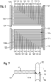
- In 6 1 is a sectional view of another embodiment of a coiled cylindrical composite formed by spirally winding a ribbon cathode and ribbon anode.
- the coil has a first end face 109a and a second end face 109b.
- the current collectors 101a and 102a together with their respective free edge strips 101c and 102c are shown here.
- the electrode materials and the separators arranged between the electrodes are not shown.
- the free edge strip 101c of the cathode current collector emerging from the end face 109a comprises a radial sequence of adjacent windings 141-156 in the winding.
- the free edge strip 102c of the anode current collector emerging from the end face 109b comprises a radial sequence of adjacent turns 160-174 in the winding.
- the free edge strips 101c and 102c were pretreated according to 4 subjected to which they each received a V-shaped cross section. In the winding itself, the anode and cathode were arranged slightly offset from one another.
- the elongate elevation 122 of the free edge strip 101c of the cathode current collector points radially inward and the elongate elevation 123 of the free edge strip 102c of the anode current collector points radially outward. It is of course also conceivable that in alternative embodiments the elongate elevations 122 and 123 point inwards in both cases or in both cases outwards, or that the elongate elevation 123 points radially inwards and the elongate elevation 122 points radially outwards.
- the width of the edge strips 101c and 102c is dimensioned in such a way that, in the case of adjacent turns, the elongated elevation of one turn is pushed into the elongated depression or indentation of a radially adjacent turn.
- the elevation 122 is pushed into the depression 121 of the next inner turn for each turn (apart from the innermost and the outermost).
- the elevation 123 is pushed into the depression 124 of the next outer turn for each turn (apart from the innermost and the outermost).
- the free edge strip 101c of the cathode current collector forms a continuous metal layer in the viewing direction perpendicular to the end face 109a, which completely covers the end face 109a in the present case.
- the free edge strip 102c of the anode current collector forms a continuous metal layer in the viewing direction perpendicular to the end face 109b, which completely covers the end face 109b in the present case.
- the end faces 109a and 109b of the coil are covered by the contact sheets 119 and 120.
- the contact plate 119 is in direct contact with the edge strip 101c
- the contact plate 120 is in direct contact with the edge strip 102c.
- the edge strips 101c and 102c can be pressed together a little.
- the edge strips 101c and 102c can exert a spring force on the contact sheets, which strengthens the contact with the sheets.
- Figure 12 illustrates the formation of a U-shaped cross-section edge strip.
- the free edge strip 101c of a cathode 101, as shown in 2 is guided longitudinally through a U-shaped gap formed by two rollers R1 and R2.
- the edge strip 101c is deformed and acquires the U-shaped cross section which characterizes it, with an elongated depression or indentation 121 on one side and an elongated elevation 122 corresponding to the depression 121 on the other side.
- an energy storage element 100 according to the invention is shown. It comprises the prismatic composite body 109 and a prismatic housing 125.
- the prismatic housing 125 is made up of the cup-shaped housing part 128 and the cover component 129.
- the contact pole 126 which is connected to the contact plate 120 by welding, is guided through the cover component 129.
- the contact pole 126 is electrically insulated from the cover component 129 by means of the insulating element 127 .
- the contact sheet 119 is welded to the bottom of the housing part 128 .
- the composite body 109 which is in the form of a prismatic stack, is located in the housing part.
- the electrodes each have a rectangular basic shape.
- the positive electrode free edge strips 101c, 103c, 105c and 107c and the negative electrode free edge strips 102c, 104c, 106c and 108c were subjected to a pretreatment according to 4 subjected to which they each received a V-shaped cross section. They thus each have one side with an elongate recess and another side with an elongate elevation.
- the free edge strips 101c, 103c, 105c, 107c emerge from one side of the prismatic stack and are all in direct contact with the contact plate 119. They are all arranged parallel to each other, the elongated elevations of the edge strips all point in the same direction.
- the free edge strips 102c, 104c, 106c and 108c emerge from the opposite side of the prismatic stack and are all in direct contact with the contact plate 120. They, too, are all arranged parallel to one another, and their elongated elevations also all point in the same direction.
- the free edge strips 101c, 103c, 105c and 107c are coupled to one another via their elongated elevations or their elongated depressions or indentations.
- the elongated ridge of edge strip 101c is inserted into the elongated depression or indentation of edge strip 103c
- the elongated ridge of edge strip 103c is inserted into the elongated depression or indentation of edge strip 105c
- the elongated ridge of edge strip 105c is inserted into the elongated depression or indentation of the edge strip 107c is inserted.
- the picture is the same on the anode side, here the elongated elevation of edge strip 108c is inserted into the elongated depression or indentation of edge strip 106c, which the elongated elevation of edge strip 106c is inserted in the elongated depression or indentation of edge strip 104c and the elongated elevation of Edge strip 104c is inserted into the elongated depression or indentation of edge strip 102c.
- the free edge strips 101c, 103c, 105c and 107c form a continuous metal layer which almost completely covers the side when viewed perpendicularly to the side of the stack from which they emerge.
- the free edge strips 102c, 104c, 106c and 108c form a continuous metal layer, viewed in the direction perpendicular to the side of the stack from which they emerge, which almost completely covers this side.
Landscapes
- Chemical & Material Sciences (AREA)
- Chemical Kinetics & Catalysis (AREA)
- Electrochemistry (AREA)
- General Chemical & Material Sciences (AREA)
- Secondary Cells (AREA)
Priority Applications (4)
| Application Number | Priority Date | Filing Date | Title |
|---|---|---|---|
| EP21200967.4A EP4164048A1 (de) | 2021-10-05 | 2021-10-05 | Energiespeicherelement und herstellungsverfahren |
| KR1020247012546A KR20240088884A (ko) | 2021-10-05 | 2022-08-04 | 에너지 저장 소자 및 제조 공정 |
| CN202280067316.5A CN118056330A (zh) | 2021-10-05 | 2022-08-04 | 蓄能器元件以及制造方法 |
| PCT/EP2022/072023 WO2023057112A1 (de) | 2021-10-05 | 2022-08-04 | Energiespeicherelement und herstellungsverfahren |
Applications Claiming Priority (1)
| Application Number | Priority Date | Filing Date | Title |
|---|---|---|---|
| EP21200967.4A EP4164048A1 (de) | 2021-10-05 | 2021-10-05 | Energiespeicherelement und herstellungsverfahren |
Publications (1)
| Publication Number | Publication Date |
|---|---|
| EP4164048A1 true EP4164048A1 (de) | 2023-04-12 |
Family
ID=78078123
Family Applications (1)
| Application Number | Title | Priority Date | Filing Date |
|---|---|---|---|
| EP21200967.4A Pending EP4164048A1 (de) | 2021-10-05 | 2021-10-05 | Energiespeicherelement und herstellungsverfahren |
Country Status (4)
| Country | Link |
|---|---|
| EP (1) | EP4164048A1 (zh) |
| KR (1) | KR20240088884A (zh) |
| CN (1) | CN118056330A (zh) |
| WO (1) | WO2023057112A1 (zh) |
Citations (7)
| Publication number | Priority date | Publication date | Assignee | Title |
|---|---|---|---|---|
| WO2007142040A1 (ja) * | 2006-06-02 | 2007-12-13 | Panasonic Corporation | 二次電池 |
| JP2015149499A (ja) | 2015-04-13 | 2015-08-20 | 日本ケミコン株式会社 | コンデンサの製造方法 |
| WO2017215900A1 (de) | 2016-06-16 | 2017-12-21 | Varta Microbattery Gmbh | Elektrochemische zelle mit optimiertem innenwiderstand |
| US20180190962A1 (en) | 2015-06-22 | 2018-07-05 | Commissariat A L'energie Atomique Et Aux Energies Alternatives | Method for producing an electrochemical bundle for a metal-ion accumulator comprising folding or coiling the foil ends around themselves |
| EP2324530B1 (en) * | 2008-09-09 | 2018-11-07 | Johnson Controls Advanced Power Solutions LLC | Electrochemical cell having a folded electrode |
| JP2019125565A (ja) * | 2018-01-19 | 2019-07-25 | 株式会社豊田自動織機 | 蓄電モジュール及びその製造方法 |
| WO2020096973A1 (en) | 2018-11-05 | 2020-05-14 | Tesla, Inc. | A cell with a tabless electrode |
-
2021
- 2021-10-05 EP EP21200967.4A patent/EP4164048A1/de active Pending
-
2022
- 2022-08-04 CN CN202280067316.5A patent/CN118056330A/zh active Pending
- 2022-08-04 KR KR1020247012546A patent/KR20240088884A/ko unknown
- 2022-08-04 WO PCT/EP2022/072023 patent/WO2023057112A1/de active Application Filing
Patent Citations (7)
| Publication number | Priority date | Publication date | Assignee | Title |
|---|---|---|---|---|
| WO2007142040A1 (ja) * | 2006-06-02 | 2007-12-13 | Panasonic Corporation | 二次電池 |
| EP2324530B1 (en) * | 2008-09-09 | 2018-11-07 | Johnson Controls Advanced Power Solutions LLC | Electrochemical cell having a folded electrode |
| JP2015149499A (ja) | 2015-04-13 | 2015-08-20 | 日本ケミコン株式会社 | コンデンサの製造方法 |
| US20180190962A1 (en) | 2015-06-22 | 2018-07-05 | Commissariat A L'energie Atomique Et Aux Energies Alternatives | Method for producing an electrochemical bundle for a metal-ion accumulator comprising folding or coiling the foil ends around themselves |
| WO2017215900A1 (de) | 2016-06-16 | 2017-12-21 | Varta Microbattery Gmbh | Elektrochemische zelle mit optimiertem innenwiderstand |
| JP2019125565A (ja) * | 2018-01-19 | 2019-07-25 | 株式会社豊田自動織機 | 蓄電モジュール及びその製造方法 |
| WO2020096973A1 (en) | 2018-11-05 | 2020-05-14 | Tesla, Inc. | A cell with a tabless electrode |
Also Published As
| Publication number | Publication date |
|---|---|
| WO2023057112A1 (de) | 2023-04-13 |
| KR20240088884A (ko) | 2024-06-20 |
| CN118056330A (zh) | 2024-05-17 |
Similar Documents
| Publication | Publication Date | Title |
|---|---|---|
| EP3916877A1 (de) | Energiespeicherzelle und herstellungsverfahren | |
| WO2022034156A1 (de) | Energiespeicherzelle und herstellungsverfahren | |
| EP3916828A1 (de) | Lithium-ionen-zelle mit hoher spezifischer energiedichte | |
| EP3965196A1 (de) | Energiespeicherzelle | |
| EP3916868A1 (de) | Energiespeicherzelle und herstellungsverfahren | |
| EP4158712B1 (de) | Lithium-ionen-zelle mit hoher spezifischer energiedichte | |
| WO2023066791A1 (de) | Lithium-ionen-zelle | |
| WO2022058342A1 (de) | Lithium-ionen-zelle mit hoher spezifischer energiedichte | |
| EP4164048A1 (de) | Energiespeicherelement und herstellungsverfahren | |
| EP4164049A1 (de) | Energiespeicherelement und herstellungsverfahren | |
| EP3905388A1 (de) | Sekundäre elektrochemische lithium-ionen-zelle | |
| EP4152434A1 (de) | Energiespeicherelement | |
| EP4135088A1 (de) | Energiespeicherelement, verbund aus energiespeicherelementen und herstellungsverfahren | |
| EP4333138A1 (de) | Energiespeicherzelle und verfahren zum herstellen einer solchen energiespeicherzelle | |
| WO2023016769A1 (de) | Energiespeicherelement, verbund aus energiespeicherelementen und herstellungsverfahren | |
| EP4270614A1 (de) | Energiespeicherzelle | |
| EP4187688A1 (de) | Energiespeicherzelle, verbund aus energiespeicherzellen und herstellungsverfahren | |
| EP4266438A1 (de) | Energiespeicherelement und herstellungsverfahren | |
| EP4250412A1 (de) | Energiespeicherzelle | |
| EP4197051A1 (de) | Energiespeicherzelle und herstellungsverfahren | |
| EP4258397A1 (de) | Energiespeicherzelle mit zylindrischem gehäuse und verfahren zur herstellung | |
| EP4329083A1 (de) | Elektrochemische energiespeicherzelle und verfahren zur herstellung | |
| WO2023194591A1 (de) | Energiespeicherzelle mit zylindrischem gehäuse und verfahren zur herstellung | |
| WO2024052435A1 (de) | Energiespeicherelement und verfahren zum herstellen eines solchen energiespeicherelements | |
| DE102022113906A1 (de) | Energiespeicherzelle mit zylindrischem Gehäuse und Verfahren zur Herstellung |
Legal Events
| Date | Code | Title | Description |
|---|---|---|---|
| PUAI | Public reference made under article 153(3) epc to a published international application that has entered the european phase |
Free format text: ORIGINAL CODE: 0009012 |
|
| STAA | Information on the status of an ep patent application or granted ep patent |
Free format text: STATUS: THE APPLICATION HAS BEEN PUBLISHED |
|
| AK | Designated contracting states |
Kind code of ref document: A1 Designated state(s): AL AT BE BG CH CY CZ DE DK EE ES FI FR GB GR HR HU IE IS IT LI LT LU LV MC MK MT NL NO PL PT RO RS SE SI SK SM TR |
|
| STAA | Information on the status of an ep patent application or granted ep patent |
Free format text: STATUS: REQUEST FOR EXAMINATION WAS MADE |
|
| 17P | Request for examination filed |
Effective date: 20231006 |
|
| RBV | Designated contracting states (corrected) |
Designated state(s): AL AT BE BG CH CY CZ DE DK EE ES FI FR GB GR HR HU IE IS IT LI LT LU LV MC MK MT NL NO PL PT RO RS SE SI SK SM TR |