EP4164034B1 - Method for manufacturing secondary battery and secondary battery manufactured using the manufacturing method - Google Patents
Method for manufacturing secondary battery and secondary battery manufactured using the manufacturing method Download PDFInfo
- Publication number
- EP4164034B1 EP4164034B1 EP21869673.0A EP21869673A EP4164034B1 EP 4164034 B1 EP4164034 B1 EP 4164034B1 EP 21869673 A EP21869673 A EP 21869673A EP 4164034 B1 EP4164034 B1 EP 4164034B1
- Authority
- EP
- European Patent Office
- Prior art keywords
- circumferential portion
- upper cover
- height
- accommodation part
- jig
- Prior art date
- Legal status (The legal status is an assumption and is not a legal conclusion. Google has not performed a legal analysis and makes no representation as to the accuracy of the status listed.)
- Active
Links
Images


Classifications
-
- B—PERFORMING OPERATIONS; TRANSPORTING
- B23—MACHINE TOOLS; METAL-WORKING NOT OTHERWISE PROVIDED FOR
- B23K—SOLDERING OR UNSOLDERING; WELDING; CLADDING OR PLATING BY SOLDERING OR WELDING; CUTTING BY APPLYING HEAT LOCALLY, e.g. FLAME CUTTING; WORKING BY LASER BEAM
- B23K26/00—Working by laser beam, e.g. welding, cutting or boring
- B23K26/20—Bonding
- B23K26/21—Bonding by welding
- B23K26/24—Seam welding
- B23K26/244—Overlap seam welding
-
- B—PERFORMING OPERATIONS; TRANSPORTING
- B23—MACHINE TOOLS; METAL-WORKING NOT OTHERWISE PROVIDED FOR
- B23K—SOLDERING OR UNSOLDERING; WELDING; CLADDING OR PLATING BY SOLDERING OR WELDING; CUTTING BY APPLYING HEAT LOCALLY, e.g. FLAME CUTTING; WORKING BY LASER BEAM
- B23K26/00—Working by laser beam, e.g. welding, cutting or boring
- B23K26/20—Bonding
- B23K26/21—Bonding by welding
-
- B—PERFORMING OPERATIONS; TRANSPORTING
- B23—MACHINE TOOLS; METAL-WORKING NOT OTHERWISE PROVIDED FOR
- B23K—SOLDERING OR UNSOLDERING; WELDING; CLADDING OR PLATING BY SOLDERING OR WELDING; CUTTING BY APPLYING HEAT LOCALLY, e.g. FLAME CUTTING; WORKING BY LASER BEAM
- B23K37/00—Auxiliary devices or processes, not specially adapted for a procedure covered by only one of the other main groups of this subclass
- B23K37/04—Auxiliary devices or processes, not specially adapted for a procedure covered by only one of the other main groups of this subclass for holding or positioning work
- B23K37/0426—Fixtures for other work
- B23K37/0435—Clamps
- B23K37/0443—Jigs
-
- H—ELECTRICITY
- H01—ELECTRIC ELEMENTS
- H01M—PROCESSES OR MEANS, e.g. BATTERIES, FOR THE DIRECT CONVERSION OF CHEMICAL ENERGY INTO ELECTRICAL ENERGY
- H01M10/00—Secondary cells; Manufacture thereof
- H01M10/05—Accumulators with non-aqueous electrolyte
- H01M10/052—Li-accumulators
-
- H—ELECTRICITY
- H01—ELECTRIC ELEMENTS
- H01M—PROCESSES OR MEANS, e.g. BATTERIES, FOR THE DIRECT CONVERSION OF CHEMICAL ENERGY INTO ELECTRICAL ENERGY
- H01M50/00—Constructional details or processes of manufacture of the non-active parts of electrochemical cells other than fuel cells, e.g. hybrid cells
- H01M50/10—Primary casings; Jackets or wrappings
-
- H—ELECTRICITY
- H01—ELECTRIC ELEMENTS
- H01M—PROCESSES OR MEANS, e.g. BATTERIES, FOR THE DIRECT CONVERSION OF CHEMICAL ENERGY INTO ELECTRICAL ENERGY
- H01M50/00—Constructional details or processes of manufacture of the non-active parts of electrochemical cells other than fuel cells, e.g. hybrid cells
- H01M50/10—Primary casings; Jackets or wrappings
- H01M50/102—Primary casings; Jackets or wrappings characterised by their shape or physical structure
- H01M50/103—Primary casings; Jackets or wrappings characterised by their shape or physical structure prismatic or rectangular
-
- H—ELECTRICITY
- H01—ELECTRIC ELEMENTS
- H01M—PROCESSES OR MEANS, e.g. BATTERIES, FOR THE DIRECT CONVERSION OF CHEMICAL ENERGY INTO ELECTRICAL ENERGY
- H01M50/00—Constructional details or processes of manufacture of the non-active parts of electrochemical cells other than fuel cells, e.g. hybrid cells
- H01M50/10—Primary casings; Jackets or wrappings
- H01M50/102—Primary casings; Jackets or wrappings characterised by their shape or physical structure
- H01M50/105—Pouches or flexible bags
-
- H—ELECTRICITY
- H01—ELECTRIC ELEMENTS
- H01M—PROCESSES OR MEANS, e.g. BATTERIES, FOR THE DIRECT CONVERSION OF CHEMICAL ENERGY INTO ELECTRICAL ENERGY
- H01M50/00—Constructional details or processes of manufacture of the non-active parts of electrochemical cells other than fuel cells, e.g. hybrid cells
- H01M50/10—Primary casings; Jackets or wrappings
- H01M50/102—Primary casings; Jackets or wrappings characterised by their shape or physical structure
- H01M50/107—Primary casings; Jackets or wrappings characterised by their shape or physical structure having curved cross-section, e.g. round or elliptic
-
- H—ELECTRICITY
- H01—ELECTRIC ELEMENTS
- H01M—PROCESSES OR MEANS, e.g. BATTERIES, FOR THE DIRECT CONVERSION OF CHEMICAL ENERGY INTO ELECTRICAL ENERGY
- H01M50/00—Constructional details or processes of manufacture of the non-active parts of electrochemical cells other than fuel cells, e.g. hybrid cells
- H01M50/10—Primary casings; Jackets or wrappings
- H01M50/102—Primary casings; Jackets or wrappings characterised by their shape or physical structure
- H01M50/109—Primary casings; Jackets or wrappings characterised by their shape or physical structure of button or coin shape
-
- H—ELECTRICITY
- H01—ELECTRIC ELEMENTS
- H01M—PROCESSES OR MEANS, e.g. BATTERIES, FOR THE DIRECT CONVERSION OF CHEMICAL ENERGY INTO ELECTRICAL ENERGY
- H01M50/00—Constructional details or processes of manufacture of the non-active parts of electrochemical cells other than fuel cells, e.g. hybrid cells
- H01M50/10—Primary casings; Jackets or wrappings
- H01M50/116—Primary casings; Jackets or wrappings characterised by the material
-
- H—ELECTRICITY
- H01—ELECTRIC ELEMENTS
- H01M—PROCESSES OR MEANS, e.g. BATTERIES, FOR THE DIRECT CONVERSION OF CHEMICAL ENERGY INTO ELECTRICAL ENERGY
- H01M50/00—Constructional details or processes of manufacture of the non-active parts of electrochemical cells other than fuel cells, e.g. hybrid cells
- H01M50/10—Primary casings; Jackets or wrappings
- H01M50/147—Lids or covers
-
- H—ELECTRICITY
- H01—ELECTRIC ELEMENTS
- H01M—PROCESSES OR MEANS, e.g. BATTERIES, FOR THE DIRECT CONVERSION OF CHEMICAL ENERGY INTO ELECTRICAL ENERGY
- H01M50/00—Constructional details or processes of manufacture of the non-active parts of electrochemical cells other than fuel cells, e.g. hybrid cells
- H01M50/10—Primary casings; Jackets or wrappings
- H01M50/147—Lids or covers
- H01M50/148—Lids or covers characterised by their shape
- H01M50/15—Lids or covers characterised by their shape for prismatic or rectangular cells
-
- H—ELECTRICITY
- H01—ELECTRIC ELEMENTS
- H01M—PROCESSES OR MEANS, e.g. BATTERIES, FOR THE DIRECT CONVERSION OF CHEMICAL ENERGY INTO ELECTRICAL ENERGY
- H01M50/00—Constructional details or processes of manufacture of the non-active parts of electrochemical cells other than fuel cells, e.g. hybrid cells
- H01M50/10—Primary casings; Jackets or wrappings
- H01M50/147—Lids or covers
- H01M50/148—Lids or covers characterised by their shape
- H01M50/152—Lids or covers characterised by their shape for cells having curved cross-section, e.g. round or elliptic
-
- H—ELECTRICITY
- H01—ELECTRIC ELEMENTS
- H01M—PROCESSES OR MEANS, e.g. BATTERIES, FOR THE DIRECT CONVERSION OF CHEMICAL ENERGY INTO ELECTRICAL ENERGY
- H01M50/00—Constructional details or processes of manufacture of the non-active parts of electrochemical cells other than fuel cells, e.g. hybrid cells
- H01M50/10—Primary casings; Jackets or wrappings
- H01M50/147—Lids or covers
- H01M50/148—Lids or covers characterised by their shape
- H01M50/153—Lids or covers characterised by their shape for button or coin cells
-
- H—ELECTRICITY
- H01—ELECTRIC ELEMENTS
- H01M—PROCESSES OR MEANS, e.g. BATTERIES, FOR THE DIRECT CONVERSION OF CHEMICAL ENERGY INTO ELECTRICAL ENERGY
- H01M50/00—Constructional details or processes of manufacture of the non-active parts of electrochemical cells other than fuel cells, e.g. hybrid cells
- H01M50/10—Primary casings; Jackets or wrappings
- H01M50/147—Lids or covers
- H01M50/155—Lids or covers characterised by the material
-
- H—ELECTRICITY
- H01—ELECTRIC ELEMENTS
- H01M—PROCESSES OR MEANS, e.g. BATTERIES, FOR THE DIRECT CONVERSION OF CHEMICAL ENERGY INTO ELECTRICAL ENERGY
- H01M50/00—Constructional details or processes of manufacture of the non-active parts of electrochemical cells other than fuel cells, e.g. hybrid cells
- H01M50/10—Primary casings; Jackets or wrappings
- H01M50/147—Lids or covers
- H01M50/166—Lids or covers characterised by the methods of assembling casings with lids
-
- H—ELECTRICITY
- H01—ELECTRIC ELEMENTS
- H01M—PROCESSES OR MEANS, e.g. BATTERIES, FOR THE DIRECT CONVERSION OF CHEMICAL ENERGY INTO ELECTRICAL ENERGY
- H01M50/00—Constructional details or processes of manufacture of the non-active parts of electrochemical cells other than fuel cells, e.g. hybrid cells
- H01M50/10—Primary casings; Jackets or wrappings
- H01M50/147—Lids or covers
- H01M50/166—Lids or covers characterised by the methods of assembling casings with lids
- H01M50/169—Lids or covers characterised by the methods of assembling casings with lids by welding, brazing or soldering
-
- B—PERFORMING OPERATIONS; TRANSPORTING
- B23—MACHINE TOOLS; METAL-WORKING NOT OTHERWISE PROVIDED FOR
- B23K—SOLDERING OR UNSOLDERING; WELDING; CLADDING OR PLATING BY SOLDERING OR WELDING; CUTTING BY APPLYING HEAT LOCALLY, e.g. FLAME CUTTING; WORKING BY LASER BEAM
- B23K2101/00—Articles made by soldering, welding or cutting
- B23K2101/36—Electric or electronic devices
-
- H—ELECTRICITY
- H01—ELECTRIC ELEMENTS
- H01M—PROCESSES OR MEANS, e.g. BATTERIES, FOR THE DIRECT CONVERSION OF CHEMICAL ENERGY INTO ELECTRICAL ENERGY
- H01M50/00—Constructional details or processes of manufacture of the non-active parts of electrochemical cells other than fuel cells, e.g. hybrid cells
- H01M50/10—Primary casings; Jackets or wrappings
- H01M50/116—Primary casings; Jackets or wrappings characterised by the material
- H01M50/117—Inorganic material
- H01M50/119—Metals
-
- Y—GENERAL TAGGING OF NEW TECHNOLOGICAL DEVELOPMENTS; GENERAL TAGGING OF CROSS-SECTIONAL TECHNOLOGIES SPANNING OVER SEVERAL SECTIONS OF THE IPC; TECHNICAL SUBJECTS COVERED BY FORMER USPC CROSS-REFERENCE ART COLLECTIONS [XRACs] AND DIGESTS
- Y02—TECHNOLOGIES OR APPLICATIONS FOR MITIGATION OR ADAPTATION AGAINST CLIMATE CHANGE
- Y02E—REDUCTION OF GREENHOUSE GAS [GHG] EMISSIONS, RELATED TO ENERGY GENERATION, TRANSMISSION OR DISTRIBUTION
- Y02E60/00—Enabling technologies; Technologies with a potential or indirect contribution to GHG emissions mitigation
- Y02E60/10—Energy storage using batteries
-
- Y—GENERAL TAGGING OF NEW TECHNOLOGICAL DEVELOPMENTS; GENERAL TAGGING OF CROSS-SECTIONAL TECHNOLOGIES SPANNING OVER SEVERAL SECTIONS OF THE IPC; TECHNICAL SUBJECTS COVERED BY FORMER USPC CROSS-REFERENCE ART COLLECTIONS [XRACs] AND DIGESTS
- Y02—TECHNOLOGIES OR APPLICATIONS FOR MITIGATION OR ADAPTATION AGAINST CLIMATE CHANGE
- Y02P—CLIMATE CHANGE MITIGATION TECHNOLOGIES IN THE PRODUCTION OR PROCESSING OF GOODS
- Y02P70/00—Climate change mitigation technologies in the production process for final industrial or consumer products
- Y02P70/50—Manufacturing or production processes characterised by the final manufactured product
Definitions
- the present invention relates to a method for manufacturing a secondary battery and a secondary battery manufactured by using the manufacturing method, and more particularly, to a method for manufacturing a secondary battery, in which, when a thin film can is welded, a bonding portion is improved in adhesion to prevent an non-welded portion from occurring, thereby remarkably improving sealing properties, and a secondary battery manufactured by using the manufacturing method.
- lithium secondary batteries such as lithium ion batteries and lithium ion polymer batteries having advantages such as high energy density, discharge voltage, and output stability.
- the secondary batteries are classified into cylindrical batteries and prismatic batteries, in which an electrode assembly is embedded in a cylindrical or prismatic metal can, and pouch-type batteries, in which an electrode assembly is embedded in a pouch-type case made of an aluminum laminate sheet according to shapes of battery cases.
- a thin film can-type battery using a metal thin film has been developed and used due to an increase in customer preference for a high output and long lifespan.
- Such a thin film can-type battery is generally manufactured by accommodating an electrode assembly in a can, covering the electrode assembly, and performing laser welding (the thin film can means a thin metal). Also, in the laser welding, it is necessary to manufacture a product having excellent sealing properties by preventing a non-welded portion from occurring.
- JP 2012 028490 A discloses a method of manufacturing an electrochemical device by laser welding of a lid onto the frame part using an appropriate jig.
- the present invention has been devised to solve the above problems, and an object of the present invention is to provide a method for manufacturing a secondary battery, in which, when a thin film can is welded, a bonding portion is improved in adhesion to prevent an non-welded portion from occurring, thereby remarkably improving sealing properties, and a secondary battery manufactured by using the manufacturing method.
- a method for manufacturing a secondary battery according to the present invention comprises: a welding preparation process of preparing a lower can comprising an accommodation part in which an electrode assembly is accommodated, and an upper cover covering an upper opening of the lower can; a gripping process of gripping an end of a lower can circumferential portion and an end of an upper cover circumferential portion at upper and lower portions by using an upper jig and a lower jig in order to weld the lower can circumferential portion that is a portion extending outward from an edge of the accommodation part to the upper cover circumferential portion that is a circumferential area of the upper cover; and a welding process of irradiating laser onto a bonding portion that is a point, at which the lower can circumferential portion and the upper cover circumferential portion are bonded to each other, to bond the lower can circumferential portion to the upper cover circumferential portion through laser welding.
- the laser welding may be performed in a state in which a height (b) of the accommodation part is formed to be higher than a height (a) of the end of the lower can circumferential portion.
- a height of a central point of the upper cover may be higher than the height b of the accommodation part.
- the lower jig may comprise a bottom part on which the lower can is placed and a sidewall formed on a circumference of the bottom part, the height (b) may mean a distance from the bottom part to an upper end of the accommodation part, and the height (a) of the end of the lower can circumferential portion may mean a distance from the bottom part to the end of the lower can circumferential portion.
- an upper pressing surface that is a surface pressing the end of the upper cover circumferential portion in the upper jig and a lower pressing surface that is a surface pressing the end of the lower can circumferential portion in the lower jig may be parallel to the bottom part.
- a value (b-a) obtained by subtracting the height (a) of the end of the lower can circumferential portion from the height (b) of the accommodation part may be greater than or equal to a thickness of a thinner base material of the lower can and the upper cover, which are welding base materials, and be less than three times the thickness of the thinner base material.
- an upper pressing surface that is a surface pressing the end of the upper cover circumferential portion in the upper jig may further extend in a direction of the laser than a lower pressing surface that is a surface pressing the end of the lower can circumferential portion in the lower jig.
- a width (c) of the upper pressing surface may be greater than a width (d) of the lower pressing surface.
- An outer end point of the upper pressing surface and an outer end point of the lower pressing surface may be disposed in the same vertical line.
- the upper jig may be provided in a right-angled triangle shape in cross section, and in the welding process, the upper jig may be disposed so that an oblique side of the right-angled triangle faces the laser.
- a secondary battery according to the present invention comprises: an electrode assembly; a lower can comprising an accommodation part in which the electrode assembly is accommodated; and an upper cover configured to cover an upper opening of the lower can, wherein the lower can comprises a lower can circumferential portion that is a portion extending outward from an edge of the accommodation part, the upper cover comprises an upper cover circumferential portion bonded to the lower can circumferential portion as a circumferential area of the upper cover, and a bonding portion that is a point at which the lower can circumferential portion and the upper cover circumferential portion are bonded to each other has a height lower than a height (b) of the accommodation part.
- a height of a central point of the upper cover may be higher than the height (b) of the accommodation part.
- the method for manufacturing the secondary battery according to the present invention may comprise: the welding preparation process of preparing the lower can comprising the accommodation part in which the electrode assembly is accommodated, and the upper cover covering the upper opening of the lower can; the gripping process of gripping the end of the lower can circumferential portion and the end of the upper cover circumferential portion at the upper and lower portions by using the upper jig and the lower jig in order to weld the lower can circumferential portion that is the portion extending outward from the edge of the accommodation part to the upper cover circumferential portion that is the circumferential area of the upper cover; and the welding process of irradiating laser onto the bonding portion that is the point, at which the lower can circumferential portion and the upper cover circumferential portion are bonded to each other, to bond the lower can circumferential portion to the upper cover circumferential portion through laser welding, and thus, when the thin film can is welded, the adhesion of the bonding portion, it is possible to prevent the non-welded portion from occurring, thereby realizing
- the secondary battery according to the present invention may comprise: the electrode assembly; the lower can comprising the accommodation part in which the electrode assembly is accommodated; and the upper cover configured to cover the upper opening of the lower can, wherein the lower can may comprise the lower can circumferential portion that is the portion extending outward from the edge of the accommodation part, the upper cover may comprise the upper cover circumferential portion bonded to the lower can circumferential portion as the circumferential area of the upper cover, and a bonding portion that is the point at which the lower can circumferential portion and the upper cover circumferential portion may be bonded to each other has the height lower than the height (b) of the accommodation part. Therefore, it may be possible to realize the significantly improved sealing properties in the thin film can-type battery.
- FIG. 1 is a cross-sectional view illustrating a method for manufacturing a secondary battery through laser welding according to a related art that is Comparative Example.
- a lower can 10 comprising an accommodation part 11 in which an electrode assembly 20 is accommodated, and an upper cover 30 covering an upper opening of the lower can 10 may be prepared, and a lower can circumferential portion 12 and an upper cover circumferential portion 32 may be welded to manufacture a secondary battery.
- each of the lower can 10 and the upper cover 30 may be a thin film can made of a thin metal.
- the lower can circumferential portion 12 and the upper cover circumferential portion 32 may be disposed to overlap each other to weld the lower can circumferential portion 12 that is a portion extending outward from an edge of the accommodation part 11 to the upper cover circumferential portion 32 that is a circumferential area of the upper cover 30.
- an end 13 of the lower can circumferential portion and an end 33 of the upper cover circumferential portion may be gripped at upper and lower portions thereof by using an upper jig 50 and a lower jig 40.
- a non-welded portion may not occur, and the welding may be performed well. For example, when welding a thin plate having a thickness of 75 ⁇ m (micrometer), the non-welded portion may occur even if a gap between base metals exceeds 10 ⁇ m (micrometer).
- laser L is irradiated onto a bonding portion that is a point, at which the lower can circumferential portion 12 and the upper cover circumferential portion 32 are bonded to each other, to bond the lower can circumferential portion 12 to the upper cover circumferential portion 32 through laser welding.
- the lower jig 40 comprises a bottom part 42 on which the lower can 10 is placed and a sidewall 43 formed on a circumference of the bottom part 42.
- a height b means a distance from the bottom part 42 to an upper end of the accommodation part 11, and a height a of the end 13 of the lower can circumferential portion means a distance from the bottom part 42 to the end 13 of the lower can circumferential portion.
- a surface pressing an end 33 of the upper cover circumferential portion is referred to as an upper pressing surface 51 in the upper jig 50
- a surface pressing the end 13 of the lower can circumferential portion is referred to as a lower pressing surface 41
- a width c of the upper pressing surface 51 and a width d of the lower pressing surface 41 are formed to be the same in Comparative Example. That is, the upper pressing surface 51 and the lower pressing surface 41 have widths corresponding to each other and face each other vertically, and an orthographic projection of the upper pressing surface 51 becomes the lower pressing surface 41.
- an inner end point of the upper pressing surface 51 and an inner end point of the lower pressing surface 41 may be disposed in the same vertical line.
- the secondary battery is manufactured through the laser welding in the same manner as in Comparative Example.
- two base materials that is, the lower can circumferential portion 12 and the upper cover circumferential portion 32 are in close contact with each other at both ends, possibility of occurrence of the gap is high at a portion at which actual welding is performed. Therefore, there is a problem because adhesion is not performed properly, resulting in non-welded portion and poor sealing properties.
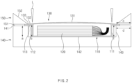
- FIG. 2 is a cross-sectional view illustrating a method for manufacturing a secondary battery through laser welding according to Embodiment 1 of the present invention.
- a method for manufacturing a secondary battery according to Example 1 of the present invention comprises a welding preparation process, a gripping process, and a welding process.
- the welding preparation process is a process of preparing a lower can 110 comprising an accommodation part 111 in which an electrode assembly 120 is accommodated, and an upper cover 130 covering an upper opening of the lower can 110.
- the accommodation part 111 of the lower can 110 may have a space recessed downward, and the upper cover 130 may have a flat plate shape.
- Each of the lower can 110 and the upper cover 130 may be a thin film can made of a thin metal.
- a lower can circumferential portion 112 that is a portion extending outward from an edge of the accommodation part 111 to an upper cover circumferential portion 132 that is a circumferential area of the upper cover 130
- the lower can circumferential portion 112 and the upper cover circumferential portion 132 are disposed to overlap each other, and an end 113 of the lower can circumferential portion and an end 133 of the upper cover circumferential portion are gripped at upper and lower portions thereof by using an upper jig 150 and a lower jig 140.
- laser L is irradiated onto a bonding portion that is a point, at which the lower can circumferential portion 112 and the upper cover circumferential portion 132 are bonded to each other, to bond the lower can circumferential portion 112 to the upper cover circumferential portion 132 through laser welding.
- the laser welding is performed in a state in which a height b of the accommodation part 111 is formed to be higher than a height a of the end 113 of the lower can circumferential portion.
- the lower jig 140 comprises a bottom part 142 on which the lower can 110 is placed and a sidewall 143 formed on a circumference of the bottom part 142.
- the height b means a distance from the bottom part 142 to an upper end of the accommodation part 111
- the height a of the end 113 of the lower can circumferential portion means a distance from the bottom part 142 to the end 113 of the lower can circumferential portion.
- the method for manufacturing the secondary battery according to Embodiment 1 of the present invention may realize significantly improved sealing properties by preventing an occurrence of a non-welded portion by improving adhesion of the bonding portion through the welding in this manner.
- One method of interpreting this may be interpreted that, as the bottom part 142 of the lower jig 140 pushes up the accommodation part 111 of the lower can 110, an edge of the accommodation part 111 applies the force of pushing up the lower can circumferential portion 112 so that the close contact is reliably realized at the bonding portion.
- the upper jig 150 applies relatively downward pushing force to the end 133 of the upper cover circumferential portion so that the close contact is reliably realized at the bonding portion.
- the upper pressing surface 151 that is a surface pressing the end 133 of the upper cover circumferential portion in the upper jig 150 and the lower pressing surface 141 that is a surface pressing the end 113 of the lower can circumferential portion in the lower jig 140 may be parallel to the bottom part 142 of the lower jig 140.
- force at which an edge of the accommodation part 111 pushes up the lower can circumferential portion 112 may act more strongly.
- force at which the upper jig 150 pushes relatively down the end 133 of the upper cover circumferential portion may act more strongly.
- a height of a central point 131 of the upper cover may be higher than the height b of the accommodation part 111. This may be a shape that appears because the upper cover 130 is provided as a thin film can.
- a value b-a obtained by subtracting the height a of the end 113 of the lower can circumferential portion from the height b of the accommodation part 111 may be greater than or equal to a thickness of a thinner base material of the lower can 110 and the upper cover 130, which are welding base materials, and be less than three times the thickness of the thinner base material.
- the value b-a is less than the thickness of the thinner base material, an effect of the present invention described above may be weakened.
- the value b-a is greater than three times the thickness of the thinner base material, deformation of the thin film can becomes severe, and an inclination of each of the lower can circumferential portion 112 and the upper cover circumferential portion 132 increases to cause a problem, in which welding performance and efficiency are relatively deteriorated.
- a width c of the upper pressing surface 151 and a width d of the lower pressing surface 141 are formed to be the same. That is, the upper pressing surface 151 and the lower pressing surface 141 have widths corresponding to each other and face each other vertically, and an orthographic projection of the upper pressing surface 151 becomes the lower pressing surface 141.
- the height b of the accommodation part 111 may be higher than a height f of the lower can circumferential portion 112, and the height f of the lower can circumferential portion 112 may be higher than the height a of the end 113 of the lower can circumferential portion. This may be because a sequential inclination is formed from an upper end of the accommodation part 111 to the end 113 of the lower circumferential portion through the lower can circumferential portion.
- an effect of the force at which the upper jig 150 pushes relatively downward the end 133 of the upper cover circumferential portion may be less than that in Embodiment 2 that will be described below.
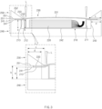
- FIG. 3 is a cross-sectional view illustrating a method for manufacturing a secondary battery through laser welding according to Embodiment 2 of the present invention.
- Embodiment 2 according to the present invention may be different from Embodiment 1 in that an upper pressing surface and a lower pressing surface have shapes different from those in Embodiment 1.
- Embodiment 1 The contents that are duplicated with Embodiment 1 will be omitted as much as possible, and Embodiment 2 will be described with a focus on the differences. That is, it is obvious that the contents that are not described in Embodiment 2 may be regarded as the contents of Embodiment 1 if necessary.
- an upper pressing surface 251 that is a surface pressing an end 233 of an upper cover circumferential portion in an upper jig 250 may further extend in a direction to laser L than a lower pressing surface 241 that is a surface pressing an end 213 of a lower can circumferential portion in a lower jig 240.
- force at which the upper jig 250 pushes relatively down the end 232 of the upper cover circumferential portion 232 may act more strongly.
- close contact may be made more reliably at a bonding portion at which welding is performed.
- a height b of the accommodation part 211 may be higher than a height a of the end 213 of the lower can circumferential portion. This is the same as in Embodiment 1.
- a width c of the upper pressing surface 251 may be greater than a width d of the lower pressing surface 241.
- an outer end point 251-1 of the upper pressing surface and an outer end point 241-1 of the lower pressing surface may be disposed in the same vertical line.
- the upper jig 250 is provided in a right-angled triangle shape in cross section, and in the welding process, the upper jig 250 may be disposed so that an oblique side 252 of the right-angled triangle faces the laser L.
- the laser irradiates the bonding portion onto the circumferential portion of the cover, possibility that a laser nozzle moves to collide with the upper cover 230 may be reduced. Thus, more stable welding may be possible.
- a secondary battery according to the present invention comprises a lower can, an upper cover, and an electrode assembly and may have the following characteristics.
- the electrode assembly may be formed by alternately stacking electrodes and separators.
- the lower can may comprise an accommodation part in which the electrode assembly is accommodated.
- the upper cover may have a shape to cover an upper opening of the lower can.
- the lower can comprises a lower can circumferential portion that is a portion extending outward from an edge of the accommodation part
- the upper cover comprises an upper cover circumferential portion bonded to the lower can circumferential portion as a circumferential area of the upper cover.
- a bonding portion that is a point at which the lower can circumferential portion and the upper cover circumferential portion are bonded to each other may have a height less than a height b of the accommodation part.
- a height of a central point of the upper cover may be higher than the height b of the accommodation part.
- the secondary battery according to the present invention may have significantly improved sealing properties at the bonding portion.
- a lower can and an upper cover were welded to each other.
- Welding was performed using 500W class laser of IPG company. The welding was performed under conditions, in which a laser beam size is 30 ⁇ m to 200 ⁇ m (micrometer), power is 50 W to 500 W, a material of the lower can is SUS316L, a thickness of the lower can is 75 ⁇ m, a material of the upper cover is SUS316L, and a thickness of the upper cover is 75 ⁇ m.
- Comparative Example 1 the welding was performed under a condition, in which a value b-a obtained by subtracting a height a of an end of the lower can circumferential portion from a height b of an accommodation part is 0 ⁇ m.
- a lower can and an upper cover were welded to each other according to the present invention.
- Welding was performed using 500W class laser of IPG company. The welding was performed under conditions, in which a laser beam size is 30 ⁇ m to 200 ⁇ m (micrometer), power is 50 W to 500 W, a material of the lower can is SUS316L, a thickness of the lower can is 75 ⁇ m, a material of the upper cover is SUS316L, and a thickness of the upper cover is 75 ⁇ m.
- FIG. 4 is a view illustrating experimental results of testing weldability for each of Comparative Example and Manufacturing Examples 1 and 2.
Landscapes
- Chemical & Material Sciences (AREA)
- Chemical Kinetics & Catalysis (AREA)
- Electrochemistry (AREA)
- General Chemical & Material Sciences (AREA)
- Engineering & Computer Science (AREA)
- Physics & Mathematics (AREA)
- Optics & Photonics (AREA)
- Mechanical Engineering (AREA)
- Plasma & Fusion (AREA)
- Manufacturing & Machinery (AREA)
- Sealing Battery Cases Or Jackets (AREA)
Description
- The present invention relates to a method for manufacturing a secondary battery and a secondary battery manufactured by using the manufacturing method, and more particularly, to a method for manufacturing a secondary battery, in which, when a thin film can is welded, a bonding portion is improved in adhesion to prevent an non-welded portion from occurring, thereby remarkably improving sealing properties, and a secondary battery manufactured by using the manufacturing method.
- In recent years, the price of energy sources increases due to the depletion of fossil fuels, the interest in environmental pollution is amplified, and the demand for eco-friendly alternative energy sources is becoming an indispensable factor for future life. Accordingly, studies on various power generation technologies such as solar power, wind power, and tidal power are continuing, and power storage devices such as batteries for more efficiently using the generated electrical energy are also of great interest.
- Furthermore, as technology development and demand for electronic mobile devices and electric vehicles using batteries increase, the demands for batteries as energy sources are rapidly increasing. Thus, many studies on batteries which are capable of meeting various demands have been conducted.
- In particular, in terms of materials, there is a high demand for lithium secondary batteries such as lithium ion batteries and lithium ion polymer batteries having advantages such as high energy density, discharge voltage, and output stability.
- The secondary batteries are classified into cylindrical batteries and prismatic batteries, in which an electrode assembly is embedded in a cylindrical or prismatic metal can, and pouch-type batteries, in which an electrode assembly is embedded in a pouch-type case made of an aluminum laminate sheet according to shapes of battery cases. In addition, recently, a thin film can-type battery using a metal thin film has been developed and used due to an increase in customer preference for a high output and long lifespan.
- Such a thin film can-type battery is generally manufactured by accommodating an electrode assembly in a can, covering the electrode assembly, and performing laser welding (the thin film can means a thin metal). Also, in the laser welding, it is necessary to manufacture a product having excellent sealing properties by preventing a non-welded portion from occurring.
- However, in the related art, in the laser welding, strong clamping is performed to prevent the non-welded portion from occurring through the strong adhesion, but in this case, deformation of the metal thin film occurs to cause a problem. However, if it is not clamped strongly, there is a problem because the adhesion is not made properly, resulting in non-welded portion and poor sealing properties.
-
JP 2012 028490 A - The present invention has been devised to solve the above problems, and an object of the present invention is to provide a method for manufacturing a secondary battery, in which, when a thin film can is welded, a bonding portion is improved in adhesion to prevent an non-welded portion from occurring, thereby remarkably improving sealing properties, and a secondary battery manufactured by using the manufacturing method.
- A method for manufacturing a secondary battery according to the present invention comprises: a welding preparation process of preparing a lower can comprising an accommodation part in which an electrode assembly is accommodated, and an upper cover covering an upper opening of the lower can; a gripping process of gripping an end of a lower can circumferential portion and an end of an upper cover circumferential portion at upper and lower portions by using an upper jig and a lower jig in order to weld the lower can circumferential portion that is a portion extending outward from an edge of the accommodation part to the upper cover circumferential portion that is a circumferential area of the upper cover; and a welding process of irradiating laser onto a bonding portion that is a point, at which the lower can circumferential portion and the upper cover circumferential portion are bonded to each other, to bond the lower can circumferential portion to the upper cover circumferential portion through laser welding.
- In the welding process, the laser welding may be performed in a state in which a height (b) of the accommodation part is formed to be higher than a height (a) of the end of the lower can circumferential portion.
- In the welding process, a height of a central point of the upper cover may be higher than the height b of the accommodation part.
- The lower jig may comprise a bottom part on which the lower can is placed and a sidewall formed on a circumference of the bottom part, the height (b) may mean a distance from the bottom part to an upper end of the accommodation part, and the height (a) of the end of the lower can circumferential portion may mean a distance from the bottom part to the end of the lower can circumferential portion.
- In the welding process, an upper pressing surface that is a surface pressing the end of the upper cover circumferential portion in the upper jig and a lower pressing surface that is a surface pressing the end of the lower can circumferential portion in the lower jig may be parallel to the bottom part.
- A value (b-a) obtained by subtracting the height (a) of the end of the lower can circumferential portion from the height (b) of the accommodation part may be greater than or equal to a thickness of a thinner base material of the lower can and the upper cover, which are welding base materials, and be less than three times the thickness of the thinner base material.
- In a welding process, an upper pressing surface that is a surface pressing the end of the upper cover circumferential portion in the upper jig may further extend in a direction of the laser than a lower pressing surface that is a surface pressing the end of the lower can circumferential portion in the lower jig.
- A width (c) of the upper pressing surface may be greater than a width (d) of the lower pressing surface.
- An outer end point of the upper pressing surface and an outer end point of the lower pressing surface may be disposed in the same vertical line.
- The upper jig may be provided in a right-angled triangle shape in cross section, and in the welding process, the upper jig may be disposed so that an oblique side of the right-angled triangle faces the laser.
- A secondary battery according to the present invention comprises: an electrode assembly; a lower can comprising an accommodation part in which the electrode assembly is accommodated; and an upper cover configured to cover an upper opening of the lower can, wherein the lower can comprises a lower can circumferential portion that is a portion extending outward from an edge of the accommodation part, the upper cover comprises an upper cover circumferential portion bonded to the lower can circumferential portion as a circumferential area of the upper cover, and a bonding portion that is a point at which the lower can circumferential portion and the upper cover circumferential portion are bonded to each other has a height lower than a height (b) of the accommodation part.
- A height of a central point of the upper cover may be higher than the height (b) of the accommodation part.
- The method for manufacturing the secondary battery according to the present invention may comprise: the welding preparation process of preparing the lower can comprising the accommodation part in which the electrode assembly is accommodated, and the upper cover covering the upper opening of the lower can; the gripping process of gripping the end of the lower can circumferential portion and the end of the upper cover circumferential portion at the upper and lower portions by using the upper jig and the lower jig in order to weld the lower can circumferential portion that is the portion extending outward from the edge of the accommodation part to the upper cover circumferential portion that is the circumferential area of the upper cover; and the welding process of irradiating laser onto the bonding portion that is the point, at which the lower can circumferential portion and the upper cover circumferential portion are bonded to each other, to bond the lower can circumferential portion to the upper cover circumferential portion through laser welding, and thus, when the thin film can is welded, the adhesion of the bonding portion, it is possible to prevent the non-welded portion from occurring, thereby realizing the significantly improved sealing properties in the thin film can-type battery.
- The secondary battery according to the present invention may comprise: the electrode assembly; the lower can comprising the accommodation part in which the electrode assembly is accommodated; and the upper cover configured to cover the upper opening of the lower can, wherein the lower can may comprise the lower can circumferential portion that is the portion extending outward from the edge of the accommodation part, the upper cover may comprise the upper cover circumferential portion bonded to the lower can circumferential portion as the circumferential area of the upper cover, and a bonding portion that is the point at which the lower can circumferential portion and the upper cover circumferential portion may be bonded to each other has the height lower than the height (b) of the accommodation part. Therefore, it may be possible to realize the significantly improved sealing properties in the thin film can-type battery.
-
-
FIG. 1 is a cross-sectional view illustrating a method for manufacturing a secondary battery through laser welding according to a related art that is Comparative Example. -
FIG. 2 is a cross-sectional view illustrating a method for manufacturing a secondary battery through laser welding according toEmbodiment 1 of the present invention. -
FIG. 3 is a cross-sectional view illustrating a method for manufacturing a secondary battery through laser welding according toEmbodiment 2 of the present invention. -
FIG. 4 is a view illustrating experimental results of testing weldability for each of Comparative Example and Manufacturing Example. - Hereinafter, preferred embodiments of the present invention will be described in detail with reference to the accompanying drawings so that those of ordinary skill in the art can easily carry out the present invention. However, the present invention may be implemented in several different forms and is not limited or restricted by the following examples.
- In order to clearly explain the present invention, detailed descriptions of portions that are irrelevant to the description or related known technologies that may unnecessarily obscure the gist of the present invention have been omitted, and in the present specification, reference symbols are added to components in each drawing. In this case, the same or similar reference numerals are assigned to the same or similar elements throughout the specification.
- Also, terms or words used in this specification and claims should not be restrictively interpreted as ordinary meanings or dictionary-based meanings, but should be interpreted as meanings and concepts conforming to the scope of the present invention on the basis of the principle that an inventor can properly define the concept of a term to describe and explain his or her invention in the best ways.
-
FIG. 1 is a cross-sectional view illustrating a method for manufacturing a secondary battery through laser welding according to a related art that is Comparative Example. - Referring to
FIG. 1 , in a method for manufacturing a secondary battery according to Comparative Example of the present invention, first, alower can 10 comprising anaccommodation part 11 in which anelectrode assembly 20 is accommodated, and anupper cover 30 covering an upper opening of thelower can 10 may be prepared, and a lower cancircumferential portion 12 and an upper covercircumferential portion 32 may be welded to manufacture a secondary battery. Here, each of thelower can 10 and theupper cover 30 may be a thin film can made of a thin metal. - The lower can
circumferential portion 12 and the upper covercircumferential portion 32 may be disposed to overlap each other to weld the lower cancircumferential portion 12 that is a portion extending outward from an edge of theaccommodation part 11 to the upper covercircumferential portion 32 that is a circumferential area of theupper cover 30. In addition, anend 13 of the lower can circumferential portion and anend 33 of the upper cover circumferential portion may be gripped at upper and lower portions thereof by using anupper jig 50 and alower jig 40. When there is no gap between the lower cancircumferential portion 12 and the upper covercircumferential portion 32 during laser welding, a non-welded portion may not occur, and the welding may be performed well. For example, when welding a thin plate having a thickness of 75 µm (micrometer), the non-welded portion may occur even if a gap between base metals exceeds 10 µm (micrometer). - After being gripped at upper and lower portions by using an
upper jig 50 and alower jig 40, laser L is irradiated onto a bonding portion that is a point, at which the lower cancircumferential portion 12 and the upper covercircumferential portion 32 are bonded to each other, to bond the lower cancircumferential portion 12 to the upper covercircumferential portion 32 through laser welding. - However, in Comparative Example, in the laser welding process, the laser welding is performed in a state in which a height b of the
accommodation part 11 and a height a of theend 13 of the lower can circumferential portion are equal to each other. - Specifically, the
lower jig 40 comprises abottom part 42 on which thelower can 10 is placed and asidewall 43 formed on a circumference of thebottom part 42. A height b means a distance from thebottom part 42 to an upper end of theaccommodation part 11, and a height a of theend 13 of the lower can circumferential portion means a distance from thebottom part 42 to theend 13 of the lower can circumferential portion. - Also, when a surface pressing an
end 33 of the upper cover circumferential portion is referred to as an upperpressing surface 51 in theupper jig 50, and a surface pressing theend 13 of the lower can circumferential portion is referred to as a lower pressing surface 41, a width c of the upperpressing surface 51 and a width d of the lower pressing surface 41 are formed to be the same in Comparative Example. That is, the upperpressing surface 51 and the lower pressing surface 41 have widths corresponding to each other and face each other vertically, and an orthographic projection of the upperpressing surface 51 becomes the lower pressing surface 41. In this case, an inner end point of the upperpressing surface 51 and an inner end point of the lower pressing surface 41 may be disposed in the same vertical line. - According to the related art, the secondary battery is manufactured through the laser welding in the same manner as in Comparative Example. In this case, even though two base materials, that is, the lower can
circumferential portion 12 and the upper covercircumferential portion 32 are in close contact with each other at both ends, possibility of occurrence of the gap is high at a portion at which actual welding is performed. Therefore, there is a problem because adhesion is not performed properly, resulting in non-welded portion and poor sealing properties. -
FIG. 2 is a cross-sectional view illustrating a method for manufacturing a secondary battery through laser welding according toEmbodiment 1 of the present invention. - Referring to
FIG. 2 , a method for manufacturing a secondary battery according to Example 1 of the present invention comprises a welding preparation process, a gripping process, and a welding process. - The welding preparation process is a process of preparing a lower can 110 comprising an
accommodation part 111 in which anelectrode assembly 120 is accommodated, and anupper cover 130 covering an upper opening of thelower can 110. Theaccommodation part 111 of the lower can 110 may have a space recessed downward, and theupper cover 130 may have a flat plate shape. Each of the lower can 110 and theupper cover 130 may be a thin film can made of a thin metal. - In order to weld a lower can circumferential
portion 112 that is a portion extending outward from an edge of theaccommodation part 111 to an upper covercircumferential portion 132 that is a circumferential area of theupper cover 130, in the gripping process, the lower can circumferentialportion 112 and the upper covercircumferential portion 132 are disposed to overlap each other, and anend 113 of the lower can circumferential portion and anend 133 of the upper cover circumferential portion are gripped at upper and lower portions thereof by using anupper jig 150 and alower jig 140. - After being gripped at upper and lower portions by using an
upper jig 150 and alower jig 140, in the welding process, laser L is irradiated onto a bonding portion that is a point, at which the lower can circumferentialportion 112 and the upper covercircumferential portion 132 are bonded to each other, to bond the lower can circumferentialportion 112 to the upper covercircumferential portion 132 through laser welding. - In the method for manufacturing the secondary battery according to
Embodiment 1 of the present invention, in the welding process, the laser welding is performed in a state in which a height b of theaccommodation part 111 is formed to be higher than a height a of theend 113 of the lower can circumferential portion. - Specifically, the
lower jig 140 comprises abottom part 142 on which the lower can 110 is placed and asidewall 143 formed on a circumference of thebottom part 142. The height b means a distance from thebottom part 142 to an upper end of theaccommodation part 111, and the height a of theend 113 of the lower can circumferential portion means a distance from thebottom part 142 to theend 113 of the lower can circumferential portion. - The method for manufacturing the secondary battery according to
Embodiment 1 of the present invention may realize significantly improved sealing properties by preventing an occurrence of a non-welded portion by improving adhesion of the bonding portion through the welding in this manner. - One method of interpreting this may be interpreted that, as the
bottom part 142 of thelower jig 140 pushes up theaccommodation part 111 of thelower can 110, an edge of theaccommodation part 111 applies the force of pushing up the lower can circumferentialportion 112 so that the close contact is reliably realized at the bonding portion. - Another method of interpreting this may be interpreted that the
upper jig 150 applies relatively downward pushing force to theend 133 of the upper cover circumferential portion so that the close contact is reliably realized at the bonding portion. - In addition, in the method for manufacturing the secondary battery according to
Embodiment 1 of the present invention, in the welding process, the upperpressing surface 151 that is a surface pressing theend 133 of the upper cover circumferential portion in theupper jig 150 and the lower pressing surface 141 that is a surface pressing theend 113 of the lower can circumferential portion in thelower jig 140 may be parallel to thebottom part 142 of thelower jig 140. When formed in this manner, force at which an edge of theaccommodation part 111 pushes up the lower can circumferentialportion 112 may act more strongly. Alternatively, force at which theupper jig 150 pushes relatively down theend 133 of the upper cover circumferential portion may act more strongly. - In addition, a height of a
central point 131 of the upper cover may be higher than the height b of theaccommodation part 111. This may be a shape that appears because theupper cover 130 is provided as a thin film can. - In the method of manufacturing the secondary battery according to
Embodiment 1 of the present invention, a value b-a obtained by subtracting the height a of theend 113 of the lower can circumferential portion from the height b of theaccommodation part 111 may be greater than or equal to a thickness of a thinner base material of the lower can 110 and theupper cover 130, which are welding base materials, and be less than three times the thickness of the thinner base material. - If the value b-a is less than the thickness of the thinner base material, an effect of the present invention described above may be weakened. In addition, when the value b-a is greater than three times the thickness of the thinner base material, deformation of the thin film can becomes severe, and an inclination of each of the lower can circumferential
portion 112 and the upper covercircumferential portion 132 increases to cause a problem, in which welding performance and efficiency are relatively deteriorated. - In the method for manufacturing the secondary battery according to
Embodiment 1 of the present invention, a width c of the upperpressing surface 151 and a width d of the lower pressing surface 141 are formed to be the same. That is, the upperpressing surface 151 and the lower pressing surface 141 have widths corresponding to each other and face each other vertically, and an orthographic projection of the upperpressing surface 151 becomes the lower pressing surface 141. - In this case, the height b of the
accommodation part 111 may be higher than a height f of the lower can circumferentialportion 112, and the height f of the lower can circumferentialportion 112 may be higher than the height a of theend 113 of the lower can circumferential portion. This may be because a sequential inclination is formed from an upper end of theaccommodation part 111 to theend 113 of the lower circumferential portion through the lower can circumferential portion. - In the method for manufacturing the secondary battery according to
Embodiment 1 of the present invention, since the width c of the upperpressing surface 151 and the width d of the lower pressing surface 141 are the same as each other, an effect of the force at which theupper jig 150 pushes relatively downward theend 133 of the upper cover circumferential portion may be less than that inEmbodiment 2 that will be described below. -
FIG. 3 is a cross-sectional view illustrating a method for manufacturing a secondary battery through laser welding according toEmbodiment 2 of the present invention. -
Embodiment 2 according to the present invention may be different fromEmbodiment 1 in that an upper pressing surface and a lower pressing surface have shapes different from those inEmbodiment 1. - The contents that are duplicated with
Embodiment 1 will be omitted as much as possible, andEmbodiment 2 will be described with a focus on the differences. That is, it is obvious that the contents that are not described inEmbodiment 2 may be regarded as the contents ofEmbodiment 1 if necessary. - Referring to
FIG. 3 , in the method for manufacturing the secondary battery according toEmbodiment 2 of the present invention, in a welding process, an upperpressing surface 251 that is a surface pressing anend 233 of an upper cover circumferential portion in anupper jig 250 may further extend in a direction to laser L than a lowerpressing surface 241 that is a surface pressing anend 213 of a lower can circumferential portion in alower jig 240. - In this case, force at which the
upper jig 250 pushes relatively down theend 232 of the upper covercircumferential portion 232 may act more strongly. Thus, close contact may be made more reliably at a bonding portion at which welding is performed. - In
Embodiment 2 of the present invention, a height b of theaccommodation part 211 may be higher than a height a of theend 213 of the lower can circumferential portion. This is the same as inEmbodiment 1. - Also, in
Embodiment 2 of the present invention, a width c of the upperpressing surface 251 may be greater than a width d of the lowerpressing surface 241. In addition, an outer end point 251-1 of the upper pressing surface and an outer end point 241-1 of the lower pressing surface may be disposed in the same vertical line. When each of theupper jig 250 and thelower jig 240 has the above-described shape, the lower can circumferentialportion 212 and the upper covercircumferential portion 232 may be gripped and supported remarkably stably at upper and lower portions thereof without shaking. - In the method for manufacturing the secondary battery according to
Embodiment 2 of the present invention, theupper jig 250 is provided in a right-angled triangle shape in cross section, and in the welding process, theupper jig 250 may be disposed so that anoblique side 252 of the right-angled triangle faces the laser L. When formed as described above, when the laser irradiates the bonding portion onto the circumferential portion of the cover, possibility that a laser nozzle moves to collide with theupper cover 230 may be reduced. Thus, more stable welding may be possible. - A secondary battery according to the present invention comprises a lower can, an upper cover, and an electrode assembly and may have the following characteristics.
- The electrode assembly may be formed by alternately stacking electrodes and separators. The lower can may comprise an accommodation part in which the electrode assembly is accommodated. The upper cover may have a shape to cover an upper opening of the lower can.
- The lower can comprises a lower can circumferential portion that is a portion extending outward from an edge of the accommodation part, and the upper cover comprises an upper cover circumferential portion bonded to the lower can circumferential portion as a circumferential area of the upper cover. A bonding portion that is a point at which the lower can circumferential portion and the upper cover circumferential portion are bonded to each other may have a height less than a height b of the accommodation part. In addition, a height of a central point of the upper cover may be higher than the height b of the accommodation part.
- The secondary battery according to the present invention may have significantly improved sealing properties at the bonding portion.
- A lower can and an upper cover were welded to each other. Welding was performed using 500W class laser of IPG company. The welding was performed under conditions, in which a laser beam size is 30 µm to 200 µm (micrometer), power is 50 W to 500 W, a material of the lower can is SUS316L, a thickness of the lower can is 75 µm, a material of the upper cover is SUS316L, and a thickness of the upper cover is 75 µm.
- In Comparative Example 1, the welding was performed under a condition, in which a value b-a obtained by subtracting a height a of an end of the lower can circumferential portion from a height b of an accommodation part is 0 µm.
- A lower can and an upper cover were welded to each other according to the present invention. Welding was performed using 500W class laser of IPG company. The welding was performed under conditions, in which a laser beam size is 30 µm to 200 µm (micrometer), power is 50 W to 500 W, a material of the lower can is SUS316L, a thickness of the lower can is 75 µm, a material of the upper cover is SUS316L, and a thickness of the upper cover is 75 µm.
- In Manufacturing Example 1, the welding was performed under a condition, in which a value b-a obtained by subtracting a height a of an end of the lower can circumferential portion from a height b of an accommodation part is 75 µm.
- Welding was performed under the same condition as in Manufacturing Example 1 except that the welding was performed under the condition, in which a value b-a obtained by subtracting a height a of an end of a lower can circumferential portion from a height b of an accommodation part is 150 µm.
-
FIG. 4 is a view illustrating experimental results of testing weldability for each of Comparative Example and Manufacturing Examples 1 and 2. - In the case of Comparative Example 1, in which the welding is performed under the condition, in which the value b-a is 0 µ m (i.e., values of a and b are the same), a cross-sectional view of the welded portion is illustrated at a left ① in
FIG. 4 . In Comparative Example 1, it is seen that an non-welded portion occurs due to an occurrence of a gap between the lower can and the upper cover. - In the case of Manufacturing Example 1, in which the welding is performed under the condition, in which the value b-a is 75 µm (i.e., the value b is greater 75 µm than the value a), a cross-sectional view of the welded portion is illustrated in the middle ② in
FIG. 4 . In the case of Manufacturing Example 1, it is seen that good welding is achieved because a gap does not occur between the lower can and the upper cover. - In the case of Manufacturing Example 2, in which the welding is performed under the condition, in which the value b-a is 150 µ m (i.e., the value b is greater 150 µ m than the value a), a cross-sectional view of the welded portion is illustrated at a right ③ in
FIG. 4 . In the case of Manufacturing Example 2, it is seen that the welding is performed in a state in which strong adhesion is provided between the lower can and the upper cover, and stronger bonding is provided rather than that of Manufacturing Example 1. - While the embodiments of the present invention have been described with reference to the specific embodiments, it will be apparent to those skilled in the art that various changes and modifications may be made without departing from the scope of the invention as defined in the following claims.
-
- 10, 110, 210: Lower can
- 11, 111, 211: Accommodation part
- 12, 112, 212: Lower can circumferential portion
- 13, 113, 213: End of lower can circumferential portion
- 20, 120, 220: Electrode assembly
- 30, 130, 230: Upper cover
- 31, 131, 231: Central point of upper cover
- 32, 132, 232: Circumferential portion of upper cover
- 33, 133, 233: End of upper cover circumferential portion
- 40, 140, 240: Lower jig
- 41, 141, 241: Lower pressing surface
- 42, 142, 242: Bottom part
- 43, 143, 243: Sidewall
- 50, 150, 250: Upper jig
- 51, 151, 251: Upper pressing surface
- 52, 152, 252: Oblique side of right-angled triangle
- L: Laser
Claims (12)
- A method for manufacturing a secondary battery, the method comprising:a welding preparation process of preparing a lower can (110)comprising an accommodation part (111) in which an electrodeassembly is accommodated, and an upper cover (130) covering anupper opening of the lower can;a gripping process of gripping an end of a lower can circumferential portion (112)and an end of an upper cover circumferential portion (132)at upper and lower portions by using an upper jig (150) and a lower jig (140)in order to weld the lower can circumferential portion that is a portion extending outward from an edge of the accommodation part to the upper cover circumferential portion that is a circumferential area of the upper cover; anda welding process of irradiating laser (L) onto a bonding
portion that is a point, at which the lower can circumferential portion (112)and the upper cover circumferential portion (132)are bonded to each other, to bond the lower can circumferential portion to the upper cover circumferential portion through laser welding,
wherein, in the welding process, the laser welding is performed in a state in which a height (b) of the accommodation part is formed to be higher than a height (a) of the end (113)of the lower can circumferential portion. - The method of claim 1, wherein, in the welding process, the laser welding is performed in a state in which the height (b) of the accommodation part is higher than a height (f) of the lower can circumferential portion, and the height (f) of the lower can circumferential portion is higher than the height (a) of the end of the lower can circumferential portion.
- The method of claim 2, wherein, in the welding process, a height of a central point of the upper cover is higher than the height (b) of the accommodation part.
- The method of claim 1, wherein the lower jig comprises a bottom part on which the lower can is placed and a sidewall formed on a circumference of the bottom part,the height (b) means a distance from the bottom part to an upper end of the accommodation part, andthe height (a) of the end of the lower can circumferential portion means a distance from the bottom part to the end of the lower can circumferential portion.
- The method of claim 4, wherein, in the welding process, an upper pressing surface that is a surface pressing the end of the upper cover circumferential portion in the upper jig and a lower pressing surface that is a surface pressing the end of the lower can circumferential portion in the lower jig are parallel to the bottom part.
- The method of claim 1, wherein a value (b-a) obtained by subtracting the height (a) of the end of the lower can circumferential portion from the height (b) of the accommodation part is greater than or equal to a thickness of a thinner base material of the lower can and the upper cover, which are welding base materials, and is less than three times the thickness of the thinner base material.
- The method of claim 1, wherein, in a welding process, an upper pressing surface that is a surface pressing the end of the upper cover circumferential portion in the upper jig further extends in a direction to the laser than a lower pressing surface that is a surface pressing the end of the lower can circumferential portion in the lower jig.
- The method of claim 7, wherein a width (c) of the upper pressing surface is greater than a width (d) of the lower pressing surface.
- The method of claim 8, wherein an outer end point of the upper pressing surface and an outer end point of the lower pressing surface are disposed in the same vertical line.
- The method of claim 1, wherein the upper jig is provided in a right-angled triangle shape in cross section, and
in the welding process, the upper jig is disposed so that an oblique side of the right-angled triangle faces the laser. - A secondary battery comprising:an electrode assembly (120);a lower can (110) comprising an accommodation part (111) in which
the electrode assembly is accommodated; andan upper cover (130) configured to cover an upper opening of the lower can,wherein the lower can comprises a lower can circumferential portion (112) that is a portion extending outward from an edge of the accommodation part,the upper cover comprises an upper cover circumferential portion (132) bonded to the lower can circumferential portion as a circumferential area of the upper cover, anda bonding portion that is a point at which the lower can circumferential portion (112) and the upper cover circumferential portion (132) are bonded to each other has a height lower than a height (b) of the accommodation part. - The secondary battery of claim 11, wherein a height of a central point of the upper cover is higher than the height (b) of the accommodation part.
Applications Claiming Priority (2)
| Application Number | Priority Date | Filing Date | Title |
|---|---|---|---|
| KR1020200119504A KR102852652B1 (en) | 2020-09-16 | 2020-09-16 | Manufacturing method for secondary battery and secondary battery manufactured by the same |
| PCT/KR2021/012493 WO2022060051A1 (en) | 2020-09-16 | 2021-09-14 | Secondary battery manufacturing method, and secondary battery manufactured using same |
Publications (3)
| Publication Number | Publication Date |
|---|---|
| EP4164034A1 EP4164034A1 (en) | 2023-04-12 |
| EP4164034A4 EP4164034A4 (en) | 2024-06-26 |
| EP4164034B1 true EP4164034B1 (en) | 2025-03-05 |
Family
ID=80777157
Family Applications (1)
| Application Number | Title | Priority Date | Filing Date |
|---|---|---|---|
| EP21869673.0A Active EP4164034B1 (en) | 2020-09-16 | 2021-09-14 | Method for manufacturing secondary battery and secondary battery manufactured using the manufacturing method |
Country Status (8)
| Country | Link |
|---|---|
| US (1) | US12531300B2 (en) |
| EP (1) | EP4164034B1 (en) |
| JP (1) | JP7533850B2 (en) |
| KR (1) | KR102852652B1 (en) |
| CN (1) | CN115769421B (en) |
| ES (1) | ES3020942T3 (en) |
| HU (1) | HUE070585T2 (en) |
| WO (1) | WO2022060051A1 (en) |
Family Cites Families (34)
| Publication number | Priority date | Publication date | Assignee | Title |
|---|---|---|---|---|
| JPS54143818A (en) * | 1978-04-28 | 1979-11-09 | Citizen Watch Co Ltd | Flat watch battery |
| JPS5646735A (en) * | 1979-09-25 | 1981-04-28 | Japan Styrene Paper Co Ltd | Freparation of polyolefin series resin foamed molding body |
| JPH03283353A (en) * | 1990-03-30 | 1991-12-13 | Shin Kobe Electric Mach Co Ltd | Small sealed container |
| JPH0433787A (en) * | 1990-05-29 | 1992-02-05 | Shin Kobe Electric Mach Co Ltd | Small-sized airtight vessel |
| JP2949823B2 (en) * | 1990-10-12 | 1999-09-20 | 株式会社村田製作所 | Method for manufacturing flat type electrochemical device |
| JP3177298B2 (en) | 1992-05-11 | 2001-06-18 | 三洋電機株式会社 | Battery and battery sealing method |
| JPH1147956A (en) | 1997-08-04 | 1999-02-23 | Showa Alum Corp | Ultrasonic joining method for metal containers |
| JP2003132857A (en) | 2001-10-25 | 2003-05-09 | Toyota Motor Corp | Sealed secondary battery and method of manufacturing the same |
| US20040062985A1 (en) | 2002-09-30 | 2004-04-01 | Aamodt Paul B. | Contoured battery for implantable medical devices and method of manufacture |
| JP4316861B2 (en) | 2002-11-28 | 2009-08-19 | パナソニック株式会社 | Square battery and manufacturing method thereof |
| JP2005026040A (en) | 2003-07-01 | 2005-01-27 | Matsushita Electric Ind Co Ltd | Square battery and manufacturing method thereof |
| KR100631057B1 (en) | 2003-09-19 | 2006-10-04 | 한국 파워셀 주식회사 | Lithium-ion Secondary Battery |
| JP5227494B2 (en) | 2005-06-02 | 2013-07-03 | 株式会社東芝 | Battery pack |
| JP2007210165A (en) | 2006-02-08 | 2007-08-23 | Denso Corp | Method and apparatus for welding resin using laser light |
| KR100749477B1 (en) | 2006-02-21 | 2007-08-14 | 삼성에스디아이 주식회사 | Jig for cap plate welding of secondary battery |
| KR101044596B1 (en) | 2009-02-13 | 2011-06-29 | 주식회사 세원정공 | Clamping method for laser welding of galvanized steel sheet |
| JP5793788B2 (en) * | 2009-05-21 | 2015-10-14 | エルジー ケム. エルティーディ. | Water-resistant pouch-type secondary battery |
| KR101106395B1 (en) | 2009-10-15 | 2012-01-17 | 삼성에스디아이 주식회사 | Secondary Battery and Manufacturing Method Thereof |
| JP2012028490A (en) * | 2010-07-22 | 2012-02-09 | Taiyo Yuden Co Ltd | Electrochemical device |
| KR101222601B1 (en) | 2011-02-22 | 2013-02-05 | 주식회사 에스코넥 | Method for producing metal cladding of portable appliance obtained by bonding moldings of different material |
| JP2013025978A (en) | 2011-07-20 | 2013-02-04 | Toyota Motor Corp | Manufacturing method of sealed battery |
| JP6024092B2 (en) * | 2011-10-26 | 2016-11-09 | 株式会社Gsユアサ | Metal container manufacturing method, metal container, power storage element, and power storage module |
| JP6113972B2 (en) | 2012-08-03 | 2017-04-12 | シャープ株式会社 | Secondary battery |
| JP2014065050A (en) | 2012-09-25 | 2014-04-17 | Denso Corp | Welding method |
| JP6090473B2 (en) * | 2012-12-28 | 2017-03-08 | エルジー・ケム・リミテッド | Pouch case sealing device and sealing method for secondary battery |
| WO2015072010A1 (en) | 2013-11-15 | 2015-05-21 | 日立オートモティブシステムズ株式会社 | Prismatic battery |
| KR102211361B1 (en) * | 2014-04-16 | 2021-02-03 | 삼성에스디아이 주식회사 | Curved secondary battery |
| KR101776885B1 (en) | 2014-09-25 | 2017-09-08 | 주식회사 엘지화학 | Prismatic Battery Cell Having Two or More Case Members |
| KR102104310B1 (en) * | 2016-01-26 | 2020-04-24 | 주식회사 엘지화학 | Manufacturing Apparatus for Battery Case Capable of Mounting Electrode Assembly of High Capacity Therein |
| KR102520538B1 (en) | 2017-12-05 | 2023-04-11 | 삼성에스디아이 주식회사 | Secondary Battery |
| EP3726617B1 (en) | 2017-12-13 | 2025-01-08 | Samsung SDI Co., Ltd. | Cylindrical lithium ion secondary battery |
| KR102395306B1 (en) | 2017-12-15 | 2022-05-09 | 현대자동차주식회사 | Laser welding apparatus |
| KR102489229B1 (en) * | 2018-03-02 | 2023-01-17 | 주식회사 엘지에너지솔루션 | Cylindrical Battery Having no Beading Part and Method For Manufacturing Thereof |
| KR102820124B1 (en) | 2020-08-18 | 2025-06-13 | 주식회사 엘지에너지솔루션 | Welding device for the manufacture of secondary battery and welding method using it |
-
2020
- 2020-09-16 KR KR1020200119504A patent/KR102852652B1/en active Active
-
2021
- 2021-09-14 ES ES21869673T patent/ES3020942T3/en active Active
- 2021-09-14 JP JP2022581544A patent/JP7533850B2/en active Active
- 2021-09-14 WO PCT/KR2021/012493 patent/WO2022060051A1/en not_active Ceased
- 2021-09-14 US US18/013,760 patent/US12531300B2/en active Active
- 2021-09-14 HU HUE21869673A patent/HUE070585T2/en unknown
- 2021-09-14 EP EP21869673.0A patent/EP4164034B1/en active Active
- 2021-09-14 CN CN202180048078.9A patent/CN115769421B/en active Active
Also Published As
| Publication number | Publication date |
|---|---|
| US20230327244A1 (en) | 2023-10-12 |
| CN115769421A (en) | 2023-03-07 |
| HUE070585T2 (en) | 2025-06-28 |
| EP4164034A4 (en) | 2024-06-26 |
| JP7533850B2 (en) | 2024-08-14 |
| US12531300B2 (en) | 2026-01-20 |
| ES3020942T3 (en) | 2025-05-23 |
| KR102852652B1 (en) | 2025-08-29 |
| KR20220036810A (en) | 2022-03-23 |
| EP4164034A1 (en) | 2023-04-12 |
| CN115769421B (en) | 2026-03-03 |
| WO2022060051A1 (en) | 2022-03-24 |
| JP2023532937A (en) | 2023-08-01 |
Similar Documents
| Publication | Publication Date | Title |
|---|---|---|
| US8846243B2 (en) | Electrode assembly having electrode tabs of the same size in joint portion thereof and electrochemical cell containing the same | |
| US10079370B2 (en) | Secondary battery | |
| US20150380717A1 (en) | Electrode assembly having tab-lead joint portion of minimized resistance difference between electrodes and electrochemical cell containing the same | |
| KR20180072990A (en) | Device Having Secondary Crimping Mold for Manufacturing Cylindrical Battery Cell | |
| WO2008010656A1 (en) | Electrode assembly having stable lead-tap joint and electrochemical cell containing them | |
| US7943253B2 (en) | Sealed battery and manufacturing method therefor | |
| KR100786871B1 (en) | Secondary battery | |
| EP4300647A1 (en) | Electrode assembly and battery cell including same | |
| KR102157495B1 (en) | Pouch type battery cell and manufacturing method thereof | |
| CN115732864A (en) | Battery, method of manufacturing electrode plate, and method of manufacturing battery | |
| US8765300B2 (en) | Battery manufacturing method, battery, pre-welding positive plate manufacturing method, and pre-welding positive plate | |
| KR100667945B1 (en) | Secondary battery | |
| US8574756B1 (en) | Prismatic secondary battery | |
| US20240283104A1 (en) | Electrode Tab and Method for Cutting Electrode Tab | |
| US12062797B2 (en) | Square battery | |
| EP4164034B1 (en) | Method for manufacturing secondary battery and secondary battery manufactured using the manufacturing method | |
| JP4120353B2 (en) | Secondary battery and manufacturing method thereof | |
| EP4510370B1 (en) | Battery module | |
| KR20220041427A (en) | Ultrasonic welding horn | |
| US20260112788A1 (en) | Current collector, battery cell including the same, and method of manufacturing the same | |
| KR20250097327A (en) | Secondary battery | |
| KR20250125681A (en) | Battery cell and manufacturing method of the same | |
| KR20260013805A (en) | Battery cell including electrode tab, battery module comprising the same, and battery cell mnufacturing method | |
| KR20250074618A (en) | Secondary battery | |
| KR20260052351A (en) | Battery housing and battery, battery pack and vehicle comprising the same |
Legal Events
| Date | Code | Title | Description |
|---|---|---|---|
| STAA | Information on the status of an ep patent application or granted ep patent |
Free format text: STATUS: THE INTERNATIONAL PUBLICATION HAS BEEN MADE |
|
| PUAI | Public reference made under article 153(3) epc to a published international application that has entered the european phase |
Free format text: ORIGINAL CODE: 0009012 |
|
| STAA | Information on the status of an ep patent application or granted ep patent |
Free format text: STATUS: REQUEST FOR EXAMINATION WAS MADE |
|
| 17P | Request for examination filed |
Effective date: 20230109 |
|
| AK | Designated contracting states |
Kind code of ref document: A1 Designated state(s): AL AT BE BG CH CY CZ DE DK EE ES FI FR GB GR HR HU IE IS IT LI LT LU LV MC MK MT NL NO PL PT RO RS SE SI SK SM TR |
|
| DAV | Request for validation of the european patent (deleted) | ||
| DAX | Request for extension of the european patent (deleted) | ||
| A4 | Supplementary search report drawn up and despatched |
Effective date: 20240524 |
|
| RIC1 | Information provided on ipc code assigned before grant |
Ipc: H01M 50/153 20210101ALI20240517BHEP Ipc: H01M 50/152 20210101ALI20240517BHEP Ipc: H01M 50/109 20210101ALI20240517BHEP Ipc: H01M 50/107 20210101ALI20240517BHEP Ipc: B23K 26/21 20140101ALI20240517BHEP Ipc: H01M 50/116 20210101ALI20240517BHEP Ipc: H01M 50/155 20210101ALI20240517BHEP Ipc: H01M 50/169 20210101ALI20240517BHEP Ipc: H01M 50/166 20210101AFI20240517BHEP |
|
| GRAP | Despatch of communication of intention to grant a patent |
Free format text: ORIGINAL CODE: EPIDOSNIGR1 |
|
| STAA | Information on the status of an ep patent application or granted ep patent |
Free format text: STATUS: GRANT OF PATENT IS INTENDED |
|
| INTG | Intention to grant announced |
Effective date: 20241126 |
|
| P01 | Opt-out of the competence of the unified patent court (upc) registered |
Free format text: CASE NUMBER: APP_65132/2024 Effective date: 20241210 |
|
| GRAS | Grant fee paid |
Free format text: ORIGINAL CODE: EPIDOSNIGR3 |
|
| GRAA | (expected) grant |
Free format text: ORIGINAL CODE: 0009210 |
|
| STAA | Information on the status of an ep patent application or granted ep patent |
Free format text: STATUS: THE PATENT HAS BEEN GRANTED |
|
| AK | Designated contracting states |
Kind code of ref document: B1 Designated state(s): AL AT BE BG CH CY CZ DE DK EE ES FI FR GB GR HR HU IE IS IT LI LT LU LV MC MK MT NL NO PL PT RO RS SE SI SK SM TR |
|
| REG | Reference to a national code |
Ref country code: GB Ref legal event code: FG4D |
|
| REG | Reference to a national code |
Ref country code: CH Ref legal event code: EP |
|
| REG | Reference to a national code |
Ref country code: IE Ref legal event code: FG4D |
|
| REG | Reference to a national code |
Ref country code: DE Ref legal event code: R096 Ref document number: 602021027319 Country of ref document: DE |
|
| REG | Reference to a national code |
Ref country code: ES Ref legal event code: FG2A Ref document number: 3020942 Country of ref document: ES Kind code of ref document: T3 Effective date: 20250523 |
|
| REG | Reference to a national code |
Ref country code: HU Ref legal event code: AG4A Ref document number: E070585 Country of ref document: HU |
|
| PG25 | Lapsed in a contracting state [announced via postgrant information from national office to epo] |
Ref country code: RS Free format text: LAPSE BECAUSE OF FAILURE TO SUBMIT A TRANSLATION OF THE DESCRIPTION OR TO PAY THE FEE WITHIN THE PRESCRIBED TIME-LIMIT Effective date: 20250605 |
|
| PG25 | Lapsed in a contracting state [announced via postgrant information from national office to epo] |
Ref country code: FI Free format text: LAPSE BECAUSE OF FAILURE TO SUBMIT A TRANSLATION OF THE DESCRIPTION OR TO PAY THE FEE WITHIN THE PRESCRIBED TIME-LIMIT Effective date: 20250305 |
|
| REG | Reference to a national code |
Ref country code: NL Ref legal event code: MP Effective date: 20250305 |
|
| REG | Reference to a national code |
Ref country code: LT Ref legal event code: MG9D |
|
| PG25 | Lapsed in a contracting state [announced via postgrant information from national office to epo] |
Ref country code: NO Free format text: LAPSE BECAUSE OF FAILURE TO SUBMIT A TRANSLATION OF THE DESCRIPTION OR TO PAY THE FEE WITHIN THE PRESCRIBED TIME-LIMIT Effective date: 20250605 |
|
| PGFP | Annual fee paid to national office [announced via postgrant information from national office to epo] |
Ref country code: BE Payment date: 20250417 Year of fee payment: 5 |
|
| PG25 | Lapsed in a contracting state [announced via postgrant information from national office to epo] |
Ref country code: HR Free format text: LAPSE BECAUSE OF FAILURE TO SUBMIT A TRANSLATION OF THE DESCRIPTION OR TO PAY THE FEE WITHIN THE PRESCRIBED TIME-LIMIT Effective date: 20250305 |
|
| PG25 | Lapsed in a contracting state [announced via postgrant information from national office to epo] |
Ref country code: LV Free format text: LAPSE BECAUSE OF FAILURE TO SUBMIT A TRANSLATION OF THE DESCRIPTION OR TO PAY THE FEE WITHIN THE PRESCRIBED TIME-LIMIT Effective date: 20250305 |
|
| PG25 | Lapsed in a contracting state [announced via postgrant information from national office to epo] |
Ref country code: GR Free format text: LAPSE BECAUSE OF FAILURE TO SUBMIT A TRANSLATION OF THE DESCRIPTION OR TO PAY THE FEE WITHIN THE PRESCRIBED TIME-LIMIT Effective date: 20250606 Ref country code: BG Free format text: LAPSE BECAUSE OF FAILURE TO SUBMIT A TRANSLATION OF THE DESCRIPTION OR TO PAY THE FEE WITHIN THE PRESCRIBED TIME-LIMIT Effective date: 20250305 |
|
| REG | Reference to a national code |
Ref country code: AT Ref legal event code: MK05 Ref document number: 1773810 Country of ref document: AT Kind code of ref document: T Effective date: 20250305 |
|
| PG25 | Lapsed in a contracting state [announced via postgrant information from national office to epo] |
Ref country code: NL Free format text: LAPSE BECAUSE OF FAILURE TO SUBMIT A TRANSLATION OF THE DESCRIPTION OR TO PAY THE FEE WITHIN THE PRESCRIBED TIME-LIMIT Effective date: 20250305 |
|
| PG25 | Lapsed in a contracting state [announced via postgrant information from national office to epo] |
Ref country code: SE Free format text: LAPSE BECAUSE OF FAILURE TO SUBMIT A TRANSLATION OF THE DESCRIPTION OR TO PAY THE FEE WITHIN THE PRESCRIBED TIME-LIMIT Effective date: 20250305 |
|
| PG25 | Lapsed in a contracting state [announced via postgrant information from national office to epo] |
Ref country code: SM Free format text: LAPSE BECAUSE OF FAILURE TO SUBMIT A TRANSLATION OF THE DESCRIPTION OR TO PAY THE FEE WITHIN THE PRESCRIBED TIME-LIMIT Effective date: 20250305 |
|
| PG25 | Lapsed in a contracting state [announced via postgrant information from national office to epo] |
Ref country code: PT Free format text: LAPSE BECAUSE OF FAILURE TO SUBMIT A TRANSLATION OF THE DESCRIPTION OR TO PAY THE FEE WITHIN THE PRESCRIBED TIME-LIMIT Effective date: 20250707 |
|
| PGFP | Annual fee paid to national office [announced via postgrant information from national office to epo] |
Ref country code: DE Payment date: 20250820 Year of fee payment: 5 |
|
| PG25 | Lapsed in a contracting state [announced via postgrant information from national office to epo] |
Ref country code: IT Free format text: LAPSE BECAUSE OF FAILURE TO SUBMIT A TRANSLATION OF THE DESCRIPTION OR TO PAY THE FEE WITHIN THE PRESCRIBED TIME-LIMIT Effective date: 20250305 Ref country code: PL Free format text: LAPSE BECAUSE OF FAILURE TO SUBMIT A TRANSLATION OF THE DESCRIPTION OR TO PAY THE FEE WITHIN THE PRESCRIBED TIME-LIMIT Effective date: 20250305 |
|
| PGFP | Annual fee paid to national office [announced via postgrant information from national office to epo] |
Ref country code: HU Payment date: 20250929 Year of fee payment: 5 Ref country code: GB Payment date: 20250820 Year of fee payment: 5 |
|
| PG25 | Lapsed in a contracting state [announced via postgrant information from national office to epo] |
Ref country code: AT Free format text: LAPSE BECAUSE OF FAILURE TO SUBMIT A TRANSLATION OF THE DESCRIPTION OR TO PAY THE FEE WITHIN THE PRESCRIBED TIME-LIMIT Effective date: 20250305 |
|
| PGFP | Annual fee paid to national office [announced via postgrant information from national office to epo] |
Ref country code: FR Payment date: 20250821 Year of fee payment: 5 |
|
| PG25 | Lapsed in a contracting state [announced via postgrant information from national office to epo] |
Ref country code: CZ Free format text: LAPSE BECAUSE OF FAILURE TO SUBMIT A TRANSLATION OF THE DESCRIPTION OR TO PAY THE FEE WITHIN THE PRESCRIBED TIME-LIMIT Effective date: 20250305 Ref country code: EE Free format text: LAPSE BECAUSE OF FAILURE TO SUBMIT A TRANSLATION OF THE DESCRIPTION OR TO PAY THE FEE WITHIN THE PRESCRIBED TIME-LIMIT Effective date: 20250305 |
|
| PG25 | Lapsed in a contracting state [announced via postgrant information from national office to epo] |
Ref country code: RO Free format text: LAPSE BECAUSE OF FAILURE TO SUBMIT A TRANSLATION OF THE DESCRIPTION OR TO PAY THE FEE WITHIN THE PRESCRIBED TIME-LIMIT Effective date: 20250305 |
|
| PG25 | Lapsed in a contracting state [announced via postgrant information from national office to epo] |
Ref country code: SK Free format text: LAPSE BECAUSE OF FAILURE TO SUBMIT A TRANSLATION OF THE DESCRIPTION OR TO PAY THE FEE WITHIN THE PRESCRIBED TIME-LIMIT Effective date: 20250305 |
|
| PG25 | Lapsed in a contracting state [announced via postgrant information from national office to epo] |
Ref country code: IS Free format text: LAPSE BECAUSE OF FAILURE TO SUBMIT A TRANSLATION OF THE DESCRIPTION OR TO PAY THE FEE WITHIN THE PRESCRIBED TIME-LIMIT Effective date: 20250705 |
|
| REG | Reference to a national code |
Ref country code: DE Ref legal event code: R097 Ref document number: 602021027319 Country of ref document: DE |
|
| PLBE | No opposition filed within time limit |
Free format text: ORIGINAL CODE: 0009261 |
|
| STAA | Information on the status of an ep patent application or granted ep patent |
Free format text: STATUS: NO OPPOSITION FILED WITHIN TIME LIMIT |
|
| PG25 | Lapsed in a contracting state [announced via postgrant information from national office to epo] |
Ref country code: DK Free format text: LAPSE BECAUSE OF FAILURE TO SUBMIT A TRANSLATION OF THE DESCRIPTION OR TO PAY THE FEE WITHIN THE PRESCRIBED TIME-LIMIT Effective date: 20250305 |
|
| REG | Reference to a national code |
Ref country code: CH Ref legal event code: L10 Free format text: ST27 STATUS EVENT CODE: U-0-0-L10-L00 (AS PROVIDED BY THE NATIONAL OFFICE) Effective date: 20260114 |
|
| PGFP | Annual fee paid to national office [announced via postgrant information from national office to epo] |
Ref country code: ES Payment date: 20251007 Year of fee payment: 5 |
|
| 26N | No opposition filed |
Effective date: 20251208 |