EP4164029B1 - Battery module - Google Patents
Battery module Download PDFInfo
- Publication number
- EP4164029B1 EP4164029B1 EP21869767.0A EP21869767A EP4164029B1 EP 4164029 B1 EP4164029 B1 EP 4164029B1 EP 21869767 A EP21869767 A EP 21869767A EP 4164029 B1 EP4164029 B1 EP 4164029B1
- Authority
- EP
- European Patent Office
- Prior art keywords
- inner case
- heat sink
- pressing member
- battery cells
- cooling
- Prior art date
- Legal status (The legal status is an assumption and is not a legal conclusion. Google has not performed a legal analysis and makes no representation as to the accuracy of the status listed.)
- Active
Links
Images


Classifications
-
- H—ELECTRICITY
- H01—ELECTRIC ELEMENTS
- H01M—PROCESSES OR MEANS, e.g. BATTERIES, FOR THE DIRECT CONVERSION OF CHEMICAL ENERGY INTO ELECTRICAL ENERGY
- H01M10/00—Secondary cells; Manufacture thereof
- H01M10/60—Heating or cooling; Temperature control
- H01M10/65—Means for temperature control structurally associated with the cells
- H01M10/655—Solid structures for heat exchange or heat conduction
- H01M10/6554—Rods or plates
- H01M10/6555—Rods or plates arranged between the cells
-
- H—ELECTRICITY
- H01—ELECTRIC ELEMENTS
- H01M—PROCESSES OR MEANS, e.g. BATTERIES, FOR THE DIRECT CONVERSION OF CHEMICAL ENERGY INTO ELECTRICAL ENERGY
- H01M10/00—Secondary cells; Manufacture thereof
- H01M10/60—Heating or cooling; Temperature control
- H01M10/61—Types of temperature control
- H01M10/613—Cooling or keeping cold
-
- H—ELECTRICITY
- H01—ELECTRIC ELEMENTS
- H01M—PROCESSES OR MEANS, e.g. BATTERIES, FOR THE DIRECT CONVERSION OF CHEMICAL ENERGY INTO ELECTRICAL ENERGY
- H01M10/00—Secondary cells; Manufacture thereof
- H01M10/60—Heating or cooling; Temperature control
- H01M10/65—Means for temperature control structurally associated with the cells
- H01M10/655—Solid structures for heat exchange or heat conduction
- H01M10/6551—Surfaces specially adapted for heat dissipation or radiation, e.g. fins or coatings
-
- H—ELECTRICITY
- H01—ELECTRIC ELEMENTS
- H01M—PROCESSES OR MEANS, e.g. BATTERIES, FOR THE DIRECT CONVERSION OF CHEMICAL ENERGY INTO ELECTRICAL ENERGY
- H01M10/00—Secondary cells; Manufacture thereof
- H01M10/60—Heating or cooling; Temperature control
- H01M10/65—Means for temperature control structurally associated with the cells
- H01M10/655—Solid structures for heat exchange or heat conduction
- H01M10/6554—Rods or plates
-
- H—ELECTRICITY
- H01—ELECTRIC ELEMENTS
- H01M—PROCESSES OR MEANS, e.g. BATTERIES, FOR THE DIRECT CONVERSION OF CHEMICAL ENERGY INTO ELECTRICAL ENERGY
- H01M10/00—Secondary cells; Manufacture thereof
- H01M10/60—Heating or cooling; Temperature control
- H01M10/65—Means for temperature control structurally associated with the cells
- H01M10/655—Solid structures for heat exchange or heat conduction
- H01M10/6556—Solid parts with flow channel passages or pipes for heat exchange
-
- H—ELECTRICITY
- H01—ELECTRIC ELEMENTS
- H01M—PROCESSES OR MEANS, e.g. BATTERIES, FOR THE DIRECT CONVERSION OF CHEMICAL ENERGY INTO ELECTRICAL ENERGY
- H01M50/00—Constructional details or processes of manufacture of the non-active parts of electrochemical cells other than fuel cells, e.g. hybrid cells
- H01M50/20—Mountings; Secondary casings or frames; Racks, modules or packs; Suspension devices; Shock absorbers; Transport or carrying devices; Holders
-
- H—ELECTRICITY
- H01—ELECTRIC ELEMENTS
- H01M—PROCESSES OR MEANS, e.g. BATTERIES, FOR THE DIRECT CONVERSION OF CHEMICAL ENERGY INTO ELECTRICAL ENERGY
- H01M50/00—Constructional details or processes of manufacture of the non-active parts of electrochemical cells other than fuel cells, e.g. hybrid cells
- H01M50/20—Mountings; Secondary casings or frames; Racks, modules or packs; Suspension devices; Shock absorbers; Transport or carrying devices; Holders
- H01M50/204—Racks, modules or packs for multiple batteries or multiple cells
-
- H—ELECTRICITY
- H01—ELECTRIC ELEMENTS
- H01M—PROCESSES OR MEANS, e.g. BATTERIES, FOR THE DIRECT CONVERSION OF CHEMICAL ENERGY INTO ELECTRICAL ENERGY
- H01M50/00—Constructional details or processes of manufacture of the non-active parts of electrochemical cells other than fuel cells, e.g. hybrid cells
- H01M50/20—Mountings; Secondary casings or frames; Racks, modules or packs; Suspension devices; Shock absorbers; Transport or carrying devices; Holders
- H01M50/244—Secondary casings; Racks; Suspension devices; Carrying devices; Holders characterised by their mounting method
-
- H—ELECTRICITY
- H01—ELECTRIC ELEMENTS
- H01M—PROCESSES OR MEANS, e.g. BATTERIES, FOR THE DIRECT CONVERSION OF CHEMICAL ENERGY INTO ELECTRICAL ENERGY
- H01M50/00—Constructional details or processes of manufacture of the non-active parts of electrochemical cells other than fuel cells, e.g. hybrid cells
- H01M50/20—Mountings; Secondary casings or frames; Racks, modules or packs; Suspension devices; Shock absorbers; Transport or carrying devices; Holders
- H01M50/262—Mountings; Secondary casings or frames; Racks, modules or packs; Suspension devices; Shock absorbers; Transport or carrying devices; Holders with fastening means, e.g. locks
- H01M50/264—Mountings; Secondary casings or frames; Racks, modules or packs; Suspension devices; Shock absorbers; Transport or carrying devices; Holders with fastening means, e.g. locks for cells or batteries, e.g. straps, tie rods or peripheral frames
-
- H—ELECTRICITY
- H01—ELECTRIC ELEMENTS
- H01M—PROCESSES OR MEANS, e.g. BATTERIES, FOR THE DIRECT CONVERSION OF CHEMICAL ENERGY INTO ELECTRICAL ENERGY
- H01M50/00—Constructional details or processes of manufacture of the non-active parts of electrochemical cells other than fuel cells, e.g. hybrid cells
- H01M50/20—Mountings; Secondary casings or frames; Racks, modules or packs; Suspension devices; Shock absorbers; Transport or carrying devices; Holders
- H01M50/289—Mountings; Secondary casings or frames; Racks, modules or packs; Suspension devices; Shock absorbers; Transport or carrying devices; Holders characterised by spacing elements or positioning means within frames, racks or packs
-
- Y—GENERAL TAGGING OF NEW TECHNOLOGICAL DEVELOPMENTS; GENERAL TAGGING OF CROSS-SECTIONAL TECHNOLOGIES SPANNING OVER SEVERAL SECTIONS OF THE IPC; TECHNICAL SUBJECTS COVERED BY FORMER USPC CROSS-REFERENCE ART COLLECTIONS [XRACs] AND DIGESTS
- Y02—TECHNOLOGIES OR APPLICATIONS FOR MITIGATION OR ADAPTATION AGAINST CLIMATE CHANGE
- Y02E—REDUCTION OF GREENHOUSE GAS [GHG] EMISSIONS, RELATED TO ENERGY GENERATION, TRANSMISSION OR DISTRIBUTION
- Y02E60/00—Enabling technologies; Technologies with a potential or indirect contribution to GHG emissions mitigation
- Y02E60/10—Energy storage using batteries
Definitions
- the present disclosure relates to a battery module, and more particularly, to a battery module capable of effectively cooling a plurality of battery cells by using a heat sink.
- a battery module includes a plurality of battery cells.
- the battery cell that is an electrode assembly includes a positive electrode and negative electrode collector, a separator, an active material, and an electrolyte to allow repeated charge and discharge by an electrochemical reaction between components.
- the battery cell generates heat in a process of charging or discharging.
- the battery cell may be accelerated in deterioration when the generated heat is not removed, and fired or exploded in some cases.
- the battery cells are cooled by using a heat sink. That is, as a thermal interface material (TIM) is installed between a case for storing the battery cells and the heat sink, the battery cells are indirectly cooled by the heat sink.
- TIM thermal interface material
- the battery cells are indirectly cooled by the heat sink.
- a cooling efficiency may be degraded.
- the present disclosure provides a battery module capable of effectively cooling a plurality of battery cells by using a heat sink.
- the present disclosure also provides a battery module capable of restricting or preventing a heat sink from being deformed.
- a battery module includes: an outer case having an accommodation space therein; an inner case having a storage space therein and installed in the accommodation space; a plurality of battery cells stored in the storage space; a heat sink disposed in the accommodation space and installed between the inner case and one side wall of the outer case to cool the battery cells; and a pressing part disposed in the accommodation space and having at least a portion installed between the other side wall of the outer case, which is opposite to the one side wall, and the inner case to press the inner case toward the heat sink.
- the pressing part may include: a pressing member brought into contact with the inner case to press the inner case; and a plurality of coupling members coupled to the one side wall of the outer case through the other side wall of the outer case, the pressing member, the inner case, and the heat sink.
- the coupling member may couple the outer case, the pressing member, the inner case, and the heat sink into one body.
- the pressing member may have a hollow shape.
- the coupling members may be arranged along a circumference of the inner case.
- a pressing projection that protrudes toward the inner case may be provided on a surface of the pressing member, which contacts the inner case, and an insertion groove to which the pressing projection may be inserted is defined in a surface of the inner case, which contacts the pressing member.
- a cooling projection that protrudes toward the inner case may be provided on a surface of the heat sink, which contacts the inner case, and a through hole through which the cooling projection passes may be defined in a surface of the inner case, which contacts the heat sink.
- Each of the cooling projection and the through-hole may be provided in plurality, and the cooling projections may respectively contact the battery cells through the through-holes.
- Each of the cooling projection and the through-hole may be provided in plurality, a cooling plate may be installed between the battery cells and a wall of the inner case, and the cooling projections may contact the cooling plate through the through-holes.
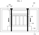
- FIG. 1 is a view illustrating a structure of a battery module in accordance with an exemplary embodiment
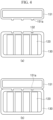
- FIG. 2 is a view illustrating a connection structure of an inner case and a heat sink in accordance with an exemplary embodiment
- FIG. 3 is a view illustrating a connection structure of an inner case and a heat sink in accordance with another exemplary embodiment
- FIG. 4 is a view illustrating a connection structure of a pressing member and the heat sink in accordance with another exemplary embodiment.
- the battery module in accordance with an exemplary embodiment is a device for supplying a power to electronic equipment or an electronic device.
- a battery module 100 includes an outer case 110, a battery cell 120, an inner case 130, a heat sink 140, and a pressing part 150.
- the outer case 110 has an accommodation space therein.
- the outer case 110 may have a cuboid box shape.
- the inner case 130, the heat sink 140, and the pressing part 150 may be accommodated in the accommodation space.
- the outer case 110 may include an outer case main body in which an opening is formed in at least a portion thereof and an outer case cover formed in the outer case main body to open and close the opening.
- the inner case 130, the heat sink 140, and the pressing part 150 may be put into the accommodation space through the opening and be installed therein.
- the exemplary embodiment is not limited to the structure and the shape of the outer case 110.
- the outer case 110 may have various structures and shapes.
- the battery cell 120 may have a cylindrical shape.
- the battery cell 120 may be provided in plurality.
- the battery cells 120 may be stored in the inner case 130.
- the battery cells 120 may be arranged at predetermined positions in the inner case 130.
- the inner case 130 may have a volume less than an internal volume of the outer case 110.
- the inner case 130 may be installed in the accommodation space of the outer case 110.
- the inner case 130 may be spaced apart from an inner wall of the outer case 110.
- the inner case 130 may include an inner case main body in which an opening is formed in at least a portion thereof and an inner case cover formed in the inner case main body to open and close the opening.
- the battery cells 120 may be put into the storage space through the opening and be installed therein.
- the exemplary embodiment is not limited to the structure and the shape of the inner case 130.
- the inner case 130 may have various structures and shapes.
- the heat sink 140 is disposed in the accommodation space of the outer case 110.
- the heat sink 140 may be installed between the inner case 130 and one side wall of the outer case 110.
- an upper portion of the heat sink 140 may contact a lower portion of the inner case 130, and a lower portion of the heat sink 140 may contact an inner bottom surface of the outer case 110.
- a separate thermal interface material may not be installed between the inner case 130 and the heat sink 140.
- the heat sink 140 may effectively cool the battery cells 120.
- a flow path through which a refrigerant flows may be formed in the heat sink 140.
- the refrigerant may be a coolant.
- the refrigerant may absorb heat from the battery cells 120 while passing through the flow path of the heat sink 140.
- the heat sink 140 may cool the battery cells 120.
- the heat sink 140 may be made of a material having a high thermal conductivity.
- the heat sink 140 may be made of aluminum or an aluminum alloy material.
- the heat sink 140 may easily absorb heat generated from the battery cells 120.
- the heat sink 140 may include a cooling projection 141.
- the cooling projection 141 may protrude from a surface (or top surface) of the heat sink 140, which contacts the inner case 130, toward the inner case 130 (or in an upward direction).
- the cooling projection 141 may have a cylindrical shape.
- the exemplary embodiment is not limited to the shape of the cooling projection 141.
- the cooling projection 141 may have various shapes.
- a through-hole 131 through which the cooling projection 141 passes may be defined in a surface (or bottom surface) of the inner case 130, which contacts the heat sink 140.
- the cooling projection 141 may have a vertical length equal to or greater than that of the through hole 131.
- the cooling projection 141 of the heat sink 140 may directly contact the battery cell 120 in the inner case 130 through the through-hole 131.
- the heat sink 140 may further effectively cool the battery cell 120.
- the cooling projection 141 may be provided in plurality.
- the plurality of through-holes 131 may be provided as many as the number of the cooling projections 141.
- each of the cooling projections 141 and the through-holes 131 may be provided as many as the number of the battery cells 120.
- Each of the cooling projections 141 and the through-holes 131 may be respectively arranged corresponding to positions of the battery cells 120.
- the cooling projections 141 may pass the through-holes 131 and directly contact the battery cells 120, respectively.
- the battery cells 120 may be further effectively cooled.
- the exemplary embodiment is not limited to the structure and the material of the heat sink 140 and the number of the cooling projections 141.
- the battery module 100 may be easily manufactured and maintained.
- the battery module 100 may further include a cooling plate 160 as illustrated in (a) of FIG. 3 .
- the cooling plate 160 When the cooling plate 160 is provided, the cooling projections 141 may contact the cooling plate 160 instead of directly contacting the battery cells 120 as illustrated in (b) of FIG. 3 .
- the cooling plate 160 may have an area less than that of the storage space of the inner case 130. Thus, the cooling plate 160 may be disposed in the storage space of the inner case 130.
- the cooling plate 160 may be installed between the battery cells and a wall of the inner case 130.
- the cooling plate 160 may be formed along a shape of a circumference of the storage space of the inner case 130.
- the cooling plate 160 may have a rectangular plate shape.
- the cooling plate 160 may have a top surface contacting all of the battery cells 120 and a bottom surface contacting the cooling projections 141. That is, the cooling projections 141 may pass the through-holes 131 and directly contact the cooling plate 160 in the inner case 130.
- the cooling plate 160 may absorb heat generated from all of the battery cells 120, and the heat sink 140 may absorb heat of the cooling plate 150.
- the heat sink 140 may easily absorb the heat of all of the battery cells 120 through the cooling plate 150.
- the cooling plate 160 may be made of a material having a high thermal conductivity.
- the cooling plate 160 may be made of aluminum or an aluminum alloy material.
- the cooling plate 160 may easily transfer the heat generated from the battery cells 120 to the heat sink 140.
- the exemplary embodiment is not limited to the shape and the material of the cooling plate 150.
- the cooling plate 160 may have various shapes and include various materials.
- the pressing part 150 is disposed in the accommodation space of the outer case 110.
- the pressing part 150 may be installed between the inner case 130 and the other side wall (or an upper wall) of the outer case 110, which is opposite to one side wall (or a lower wall) of the outer case 110.
- the pressing part 150 may press the inner case 130 toward the heat sink 140 (or in a downward direction), so that the inner case 130 closely contacts the heat sink 140.
- the pressing part 150 includes a pressing member 151 and a coupling member 152.
- the pressing member 151 may be formed along a shape of a circumference of the inner case 130.
- the pressing member 151 has an upper portion contacting an inner ceiling surface of the outer case 110 and a lower portion contacting an upper portion of the inner case 130.
- the pressing member 151 is disposed at an opposite side of the heat sink 140 with the inner case 130 therebetween.
- the pressing member 151, the inner case 130, and the heat sink 140 may be arranged in a row along a vertical direction in the accommodation space of the outer case 110.
- a bottom surface of the pressing member 151 may have an area equal to or greater than that of a top surface of the inner case 130.
- the pressing member 151 may uniformly press the entire top surface of the inner case 130 in the downward direction.
- the entire inner case 130 may uniformly and closely contact the heat sink 140.
- the pressing member 151 may be made of a material having a high thermal conductivity.
- the pressing member 151 may be made of aluminum or an aluminum alloy material.
- the heat generated from the battery cells 120 may be transferred to the inner case 130, and the pressing member 151 may dissipate the heat of the inner case 130.
- temperature increase of the battery cells 120 may be effectively restricted or prevented.
- the pressing member may have a hollow shape. That is, the pressing member 151 may have a pipe shape having an empty inside when cut into a cross-section. Thus, a weight of the pressing member 151 may be reduced. Also, a weight of the battery module 100 may be reduced.
- the pressing member 151 since the pressing member 151 has the hollow shape, the shape of the pressing member 151 may be easily deformed by a force applied from the outside. That is, the pressing member 151 may have elasticity. Thus, the pressing member 151 may press the heat sink 140 with flexibility. Thus, the pressing member 151 may stably increase a force of pressing the heat sink 140 while preventing or restricting a damage of the pressing member 151.
- a pressing projection 151a may be provided on the pressing member 151.
- the pressing projection 151a may protrude from a surface (or a bottom surface) of the pressing member, which contacts the inner case 130, toward the inner case 130 (or in the downward direction).
- the pressing projection 151a may have a cylindrical shape.
- the exemplary embodiment is not limited to the shape of the pressing projection 151a.
- the pressing projection 151a may have various shapes.
- an insertion groove 132 to which the pressing projection 151a is inserted may be defined in a surface (or a top surface) of the inner case 130, which contacts the pressing member 151.
- the pressing member 151 and the inner case 130 may be stably coupled to each other by the pressing projection 151a and the insertion groove 132.
- the pressing projection 151a may be provided in plurality.
- the insertion groove 132 may be also provided in plurality as many as the number of the pressing projections 151a.
- the pressing projections 151a may be respectively inserted to different insertion grooves 132.
- the pressing member 151 and the inner case 130 may be further stably coupled to each other as a contact area of the pressing member 151 and the inner case 130 increases, and the pressing member 151 may further effectively dissipate the heat generated from the battery cells 120 through the inner case 130.
- the exemplary embodiment is not limited to the structure and the material of the pressing member151 and the number of the pressing projections 151a.
- the pressing member 151 and the inner case 130 may be aligned in position. Since the positions of the inner case 130 and the heat sink 140 are aligned by the cooling projections 141 and the through-holes 131, the pressing member 151, the inner case 130, and the heat sink 140 may be easily aligned in the vertical direction. Thus, the battery module 100 may be easily manufactured and maintained.
- the coupling member 152 may have a bolt shape.
- the coupling member 152 may adjust a degree in which the pressing member 151 presses the inner case 130.
- the pressing member 151 may further strongly press the inner case 130 in the downward direction, and when the coupling member 152 is loosened, the force of the pressing member 151 for pressing the inner case 130 in the downward direction may be weakened.
- the coupling member 152 may extend in the vertical direction. A vertical length of the coupling member 152 may be greater than that of the accommodation space of the outer case 110 and less than that of the entire outer case 110.
- the coupling member 152 may be coupled to one side wall (or a lower wall) of the outer case 110 through the other side wall (or an upper wall) of the outer case 110, the pressing member 151, the inner case 130, and the heat sink 140.
- the coupling member 152 may couple the outer case 110, the pressing member 151, the inner case 130, and the heat sink 140 into one body so that the outer case 110, the pressing member 151, the inner case 130, and the heat sink 140 are stably coupled.
- the coupling member 152 may pass through the inner case 130 and the heat sink 140 while being spaced apart from the battery cells 120 and the flow path formed in the heat sink 140. Thus, when the coupling member 152 passes, the coupling member 152 may not damage the battery cells 120 or the flow path.
- the coupling member 152 may be provided in plurality.
- the coupling members 152 may be arranged along the circumference of the inner case 130.
- the pressing member 151 may uniformly press the entire top surface of the inner case 130 in a downward direction, and the inner case 130 may uniformly press the entire top surface of the heat sink 140 by the pressing member 151 in the downward direction.
- the heat sink 140 may be deformed by a hydraulic pressure of the refrigerant because the top surface of the heat sink 140 is not uniformly pressed.
- TIM thermal interface material
- the coupling member 152 may be made of a material having a high thermal conductivity.
- the coupling member 152 may be made of aluminum or an aluminum alloy material.
- the coupling member 152 may easily transfer heat of the storage space of the inner case 130 to the pressing member 151 or the heat sink 140.
- the battery cells 120 stored in the storage space of the inner case 130 may be further effectively cooled.
- the exemplary embodiment is not limited to the structure and the material of the coupling member 152 and a passing or coupling direction of the coupling member 152.
- the coupling member 152 may have various structures, include various materials, and have various passing or coupling directions.
- the method for manufacturing the battery module 100 may include: a process of storing battery cells 120 in a storage space of an inner case 130; a process of installing a pressing member 151, an inner case 130, and a heat sink 140 in an accommodation space of an outer case 110; and a process of coupling the outer case 110, the pressing member 151, the inner case 130, and the heat sink 140 by a coupling member 152.
- the battery cells 120 may be stored in a storage space of the inner case 130. That is, the battery cells 120 may be put into the storage space through an opened portion of an inner case main boy and then arranged at predetermined positions in a standing state. When all of the battery cells 120 are stored, an inner case cover may be installed on the inner case main body to block the opened portion of the inner case main body.
- the pressing member 151, the inner case 130, and the heat sink 140 may be installed in the accommodation space of the outer case 110. That is, the pressing member 151, the inner case 130, and the heat sink 140 may be put into the accommodation space through an opened portion of the outer case main body.
- an outer case cover may be installed on the outer case main body to block the opened portion of the outer case main body.
- pressing projections 151a of the pressing member 151 may be inserted to insertion grooves 132 in a top surface of the inner case 130, and cooling projections 141 of the heat sink 140 may be inserted to through-holes 131 in a bottom surface of the inner case 130.
- positions of the pressing member 151, the inner case 130, and the heat sink 140 may be arranged in a vertical direction in the accommodation space of the outer case 110.
- a separate thermal interface material may not be installed between the inner case 130 and the heat sink 140.
- the heat sink 140 may be disposed closer to the battery cells 120.
- the heat sink 140 may effectively cool the battery cells 120.
- the cooling projections 141 may pass the through-holes 131 and directly contact the battery cells 120 stored in the inner case 130.
- the cooling projections 141 may pass the through-holes 131 and contact the cooling plate 150.
- the heat sink 140 may be disposed closer to the battery cells 120.
- the coupling member 152 may couple the outer case 110, the pressing member 151, the inner case 130, and the heat sink 140. That is, the coupling member 152 may be coupled to a lower wall of the outer case 110 through an upper wall of the outer case 110, the pressing member 151, the inner case 130, and the heat sink 140.
- the coupling member 152 may pass a position at which the battery cells 120 are not disposed in the storage space of the inner case 130 and a portion at which a flow path is not formed in the heat sink 140.
- the coupling member 152 passes the inner case 130 or the heat sink 140, the battery cells 120 or the flow path may be prevented from being damaged.
- a plurality of coupling members 152 may be arranged along a circumference of the inner case 130.
- the pressing member 151 may uniformly press the entire top surface of the inner case 130 by the coupling member 152 in a downward direction
- the inner case 130 may uniformly press the entire top surface of the heat sink 140 by the pressing member 151 in the downward direction.
- deformation of the heat sink 140 may be restricted or prevented.
- a strength of a force of the pressing member 151 for pressing the inner case 130 in the downward direction may be adjusted by the coupling members 152.
- the coupling member 152 when the coupling member 152 is tightened downward, the pressing member 151 may further strongly press the inner case 130 in the downward direction, and when the coupling member 152 is loosened upward, the force of the pressing member 151 for pressing the inner case 130 in the downward direction may be weakened.
- a degree in which the inner case 130 presses the heat sink 140 may be adjusted so that the inner case 130 stably and closely contact the heat sink 140.
- a distance between the battery cells 120 and the heat sink 140 may decrease.
- the heat sink 140 may absorb heat generated from the battery cells 120 at a position close to the battery cells 120.
- the battery cells 120 may be effectively cooled by using the heat sink 140.
- the inner case 130 and the heat sink 140 may closely contact each other in an overall uniform manner by using the pressing part 150. Thus, deformation of the heat sink 140 may be restricted or prevented. Thus, the heat sink 140 may have an improved lifespan and durability to stably cool the battery cells 120.
- the distance between the battery cells and the heat sink may decrease.
- the heat sink may absorb the heat generated from the battery cells at the position close to the battery cells.
- the battery cells may be effectively cooled by using the heat sink.
- the case for storing the battery cells and the heat sink may closely contact each other in the overall uniform manner.
- the deformation of the heat sink may be restricted or prevented.
- the heat skin may have the improved lifespan and durability to stably cool the battery cells by using the heat sink.
Landscapes
- Chemical & Material Sciences (AREA)
- Chemical Kinetics & Catalysis (AREA)
- Electrochemistry (AREA)
- General Chemical & Material Sciences (AREA)
- Engineering & Computer Science (AREA)
- Manufacturing & Machinery (AREA)
- Secondary Cells (AREA)
- Battery Mounting, Suspending (AREA)
Description
- The present disclosure relates to a battery module, and more particularly, to a battery module capable of effectively cooling a plurality of battery cells by using a heat sink.
- In general, a battery module includes a plurality of battery cells. The battery cell that is an electrode assembly includes a positive electrode and negative electrode collector, a separator, an active material, and an electrolyte to allow repeated charge and discharge by an electrochemical reaction between components.
- Here, the battery cell generates heat in a process of charging or discharging. The battery cell may be accelerated in deterioration when the generated heat is not removed, and fired or exploded in some cases.
- Typically, the battery cells are cooled by using a heat sink. That is, as a thermal interface material (TIM) is installed between a case for storing the battery cells and the heat sink, the battery cells are indirectly cooled by the heat sink. However, as a distance between the battery cells and the heat sink increases, a cooling efficiency may be degraded.
- (Patent document 1)
KR10-2014-0077272 A - (Patent document 2)
US7393609B2 - (Patent document 3)
WO2019/230325A1 - The present disclosure provides a battery module capable of effectively cooling a plurality of battery cells by using a heat sink.
- The present disclosure also provides a battery module capable of restricting or preventing a heat sink from being deformed.
- In accordance with an exemplary embodiment, a battery module includes: an outer case having an accommodation space therein; an inner case having a storage space therein and installed in the accommodation space; a plurality of battery cells stored in the storage space; a heat sink disposed in the accommodation space and installed between the inner case and one side wall of the outer case to cool the battery cells; and a pressing part disposed in the accommodation space and having at least a portion installed between the other side wall of the outer case, which is opposite to the one side wall, and the inner case to press the inner case toward the heat sink.
- The pressing part may include: a pressing member brought into contact with the inner case to press the inner case; and a plurality of coupling members coupled to the one side wall of the outer case through the other side wall of the outer case, the pressing member, the inner case, and the heat sink. Here, the coupling member may couple the outer case, the pressing member, the inner case, and the heat sink into one body.
- The pressing member may have a hollow shape.
- The coupling members may be arranged along a circumference of the inner case.
- A pressing projection that protrudes toward the inner case may be provided on a surface of the pressing member, which contacts the inner case, and an insertion groove to which the pressing projection may be inserted is defined in a surface of the inner case, which contacts the pressing member.
- A cooling projection that protrudes toward the inner case may be provided on a surface of the heat sink, which contacts the inner case, and a through hole through which the cooling projection passes may be defined in a surface of the inner case, which contacts the heat sink.
- Each of the cooling projection and the through-hole may be provided in plurality, and the cooling projections may respectively contact the battery cells through the through-holes.
- Each of the cooling projection and the through-hole may be provided in plurality, a cooling plate may be installed between the battery cells and a wall of the inner case, and the cooling projections may contact the cooling plate through the through-holes.
- Exemplary embodiments can be understood in more detail from the following description taken in conjunction with the accompanying drawings, in which:
-
FIG. 1 is a view of a structure of a battery module in accordance with an exemplary embodiment; -
FIG. 2 is a view illustrating a connection structure of an inner case and a heat sink in accordance with an exemplary embodiment; -
FIG. 3 is a view illustrating a connection structure of an inner case and a heat sink in accordance with another exemplary embodiment; and -
FIG. 4 is a view illustrating a connection structure of a pressing member and the heat sink in accordance with an exemplary embodiment. - Hereinafter, specific embodiments will be described in detail with reference to the accompanying drawings. The present disclosure may, however, be embodied in many different forms and should not be construed as being limited to the embodiments set forth herein; rather, these embodiments are provided so that this disclosure will be thorough and complete, and will fully convey the concept of the invention to those skilled in the art. In the figures, the dimensions of layers and regions are exaggerated for clarity of illustration, and like reference numerals refer to like elements throughout.
-
FIG. 1 is a view illustrating a structure of a battery module in accordance with an exemplary embodiment,FIG. 2 is a view illustrating a connection structure of an inner case and a heat sink in accordance with an exemplary embodiment,FIG. 3 is a view illustrating a connection structure of an inner case and a heat sink in accordance with another exemplary embodiment, andFIG. 4 is a view illustrating a connection structure of a pressing member and the heat sink in accordance with another exemplary embodiment. - The battery module in accordance with an exemplary embodiment is a device for supplying a power to electronic equipment or an electronic device. Referring to
FIG. 1 , abattery module 100 includes anouter case 110, abattery cell 120, aninner case 130, aheat sink 140, and apressing part 150. - The
outer case 110 has an accommodation space therein. For example, theouter case 110 may have a cuboid box shape. Thus, theinner case 130, theheat sink 140, and thepressing part 150 may be accommodated in the accommodation space. - Here, the
outer case 110 may include an outer case main body in which an opening is formed in at least a portion thereof and an outer case cover formed in the outer case main body to open and close the opening. Thus, theinner case 130, theheat sink 140, and thepressing part 150 may be put into the accommodation space through the opening and be installed therein. However, the exemplary embodiment is not limited to the structure and the shape of theouter case 110. For example, theouter case 110 may have various structures and shapes. - The
battery cell 120 may have a cylindrical shape. Thebattery cell 120 may be provided in plurality. Thebattery cells 120 may be stored in theinner case 130. For example, thebattery cells 120 may be arranged at predetermined positions in theinner case 130. - The
inner case 130 has a storage space therein for storing the battery cells. For example, theinner case 130 may have a cuboid box shape. Thus, thebatter cells 120 may be stored in the storage space. - Also, the
inner case 130 may have a volume less than an internal volume of theouter case 110. Thus, theinner case 130 may be installed in the accommodation space of theouter case 110. Theinner case 130 may be spaced apart from an inner wall of theouter case 110. - Here, the
inner case 130 may include an inner case main body in which an opening is formed in at least a portion thereof and an inner case cover formed in the inner case main body to open and close the opening. Thus, thebattery cells 120 may be put into the storage space through the opening and be installed therein. However, the exemplary embodiment is not limited to the structure and the shape of theinner case 130. For example, theinner case 130 may have various structures and shapes. - The
heat sink 140 is disposed in the accommodation space of theouter case 110. Theheat sink 140 may be installed between theinner case 130 and one side wall of theouter case 110. For example, an upper portion of theheat sink 140 may contact a lower portion of theinner case 130, and a lower portion of theheat sink 140 may contact an inner bottom surface of theouter case 110. - Here, a separate thermal interface material (TIM) may not be installed between the
inner case 130 and theheat sink 140. Thus, as a distance between thebattery cells 120 and theheat sink 140 decreases, theheat sink 140 may effectively cool thebattery cells 120. - Also, a flow path through which a refrigerant flows may be formed in the
heat sink 140. For example, the refrigerant may be a coolant. The refrigerant may absorb heat from thebattery cells 120 while passing through the flow path of theheat sink 140. Thus, theheat sink 140 may cool thebattery cells 120. - Here, a top surface of the
heat sink 140 may have an area equal to or greater than that of a bottom surface of theinner case 130. Thus, since theheat sink 140 may contact the entire bottom surface of theinner case 130, theheat sink 140 may easily cool all of thebattery cells 120 stored in theinner case 130. - Also, the
heat sink 140 may be made of a material having a high thermal conductivity. For example, theheat sink 140 may be made of aluminum or an aluminum alloy material. Thus, theheat sink 140 may easily absorb heat generated from thebattery cells 120. - As illustrated in
FIG. 2 , theheat sink 140 may include acooling projection 141. The coolingprojection 141 may protrude from a surface (or top surface) of theheat sink 140, which contacts theinner case 130, toward the inner case 130 (or in an upward direction). For example, the coolingprojection 141 may have a cylindrical shape. However, the exemplary embodiment is not limited to the shape of thecooling projection 141. For example, the coolingprojection 141 may have various shapes. - Here, as illustrated in (a) of
FIG. 2 , a through-hole 131 through which thecooling projection 141 passes may be defined in a surface (or bottom surface) of theinner case 130, which contacts theheat sink 140. The coolingprojection 141 may have a vertical length equal to or greater than that of the throughhole 131. Thus, the coolingprojection 141 of theheat sink 140 may directly contact thebattery cell 120 in theinner case 130 through the through-hole 131. Thus, theheat sink 140 may further effectively cool thebattery cell 120. - Also, the cooling
projection 141 may be provided in plurality. The plurality of through-holes 131 may be provided as many as the number of the coolingprojections 141. For example, each of the coolingprojections 141 and the through-holes 131 may be provided as many as the number of thebattery cells 120. Each of the coolingprojections 141 and the through-holes 131 may be respectively arranged corresponding to positions of thebattery cells 120. Thus, as illustrated in (b) ofFIG. 2 , the coolingprojections 141 may pass the through-holes 131 and directly contact thebattery cells 120, respectively. Thus, as the number of thebattery cells 120 directly contacting the coolingprojections 141 increases, thebattery cells 120 may be further effectively cooled. However, the exemplary embodiment is not limited to the structure and the material of theheat sink 140 and the number of the coolingprojections 141. - Here, when the cooling
projections 141 are inserted into the through-holes 131, theinner case 130 and theheat sink 140 are aligned in position and stably coupled to each other. Thus, thebattery module 100 may be easily manufactured and maintained. - Also, the
battery module 100 may further include acooling plate 160 as illustrated in (a) ofFIG. 3 . When thecooling plate 160 is provided, the coolingprojections 141 may contact thecooling plate 160 instead of directly contacting thebattery cells 120 as illustrated in (b) ofFIG. 3 . Thecooling plate 160 may have an area less than that of the storage space of theinner case 130. Thus, thecooling plate 160 may be disposed in the storage space of theinner case 130. Thecooling plate 160 may be installed between the battery cells and a wall of theinner case 130. - Also, the
cooling plate 160 may be formed along a shape of a circumference of the storage space of theinner case 130. For example, thecooling plate 160 may have a rectangular plate shape. Thecooling plate 160 may have a top surface contacting all of thebattery cells 120 and a bottom surface contacting the coolingprojections 141. That is, the coolingprojections 141 may pass the through-holes 131 and directly contact thecooling plate 160 in theinner case 130. Thus, thecooling plate 160 may absorb heat generated from all of thebattery cells 120, and theheat sink 140 may absorb heat of thecooling plate 150. Thus, although the number of the coolingprojections 141 is less than that of thebattery cells 120, or the coolingprojections 141 and thebattery cells 120 are not aligned in position, theheat sink 140 may easily absorb the heat of all of thebattery cells 120 through thecooling plate 150. - Here, the
cooling plate 160 may be made of a material having a high thermal conductivity. For example, thecooling plate 160 may be made of aluminum or an aluminum alloy material. Thus, thecooling plate 160 may easily transfer the heat generated from thebattery cells 120 to theheat sink 140. However, the exemplary embodiment is not limited to the shape and the material of thecooling plate 150. For example, thecooling plate 160 may have various shapes and include various materials. - The
pressing part 150 is disposed in the accommodation space of theouter case 110. Thepressing part 150 may be installed between theinner case 130 and the other side wall (or an upper wall) of theouter case 110, which is opposite to one side wall (or a lower wall) of theouter case 110. Thepressing part 150 may press theinner case 130 toward the heat sink 140 (or in a downward direction), so that theinner case 130 closely contacts theheat sink 140. Thepressing part 150 includes apressing member 151 and acoupling member 152. - The pressing
member 151 may be formed along a shape of a circumference of theinner case 130. The pressingmember 151 has an upper portion contacting an inner ceiling surface of theouter case 110 and a lower portion contacting an upper portion of theinner case 130. Thus, the pressingmember 151 is disposed at an opposite side of theheat sink 140 with theinner case 130 therebetween. Thus, the pressingmember 151, theinner case 130, and theheat sink 140 may be arranged in a row along a vertical direction in the accommodation space of theouter case 110. - Here, a bottom surface of the
pressing member 151 may have an area equal to or greater than that of a top surface of theinner case 130. Thus, since theheat sink 140 may contact the entire top surface of theinner case 130, the pressingmember 151 may uniformly press the entire top surface of theinner case 130 in the downward direction. Thus, the entireinner case 130 may uniformly and closely contact theheat sink 140. - Also, the pressing
member 151 may be made of a material having a high thermal conductivity. For example, the pressingmember 151 may be made of aluminum or an aluminum alloy material. Thus, the heat generated from thebattery cells 120 may be transferred to theinner case 130, and thepressing member 151 may dissipate the heat of theinner case 130. Thus, as heat generated from upper ends of thebattery cells 120 is dissipated by the pressingmember 151, and lower ends of thebattery cells 120 are cooled by theheat sink 140, temperature increase of thebattery cells 120 may be effectively restricted or prevented. - Here, the pressing member may have a hollow shape. That is, the pressing
member 151 may have a pipe shape having an empty inside when cut into a cross-section. Thus, a weight of thepressing member 151 may be reduced. Also, a weight of thebattery module 100 may be reduced. - Also, since the
pressing member 151 has the hollow shape, the shape of thepressing member 151 may be easily deformed by a force applied from the outside. That is, the pressingmember 151 may have elasticity. Thus, the pressingmember 151 may press theheat sink 140 with flexibility. Thus, the pressingmember 151 may stably increase a force of pressing theheat sink 140 while preventing or restricting a damage of thepressing member 151. - As illustrated in
FIG. 4 , apressing projection 151a may be provided on thepressing member 151. Thepressing projection 151a may protrude from a surface (or a bottom surface) of the pressing member, which contacts theinner case 130, toward the inner case 130 (or in the downward direction). For example, thepressing projection 151a may have a cylindrical shape. However, the exemplary embodiment is not limited to the shape of thepressing projection 151a. For example, thepressing projection 151a may have various shapes. - Here, as illustrated in (a) of
FIG. 4 , aninsertion groove 132 to which thepressing projection 151a is inserted may be defined in a surface (or a top surface) of theinner case 130, which contacts thepressing member 151. The pressingmember 151 and theinner case 130 may be stably coupled to each other by thepressing projection 151a and theinsertion groove 132. - Also, the
pressing projection 151a may be provided in plurality. Theinsertion groove 132 may be also provided in plurality as many as the number of thepressing projections 151a. Thepressing projections 151a may be respectively inserted todifferent insertion grooves 132. As illustrated in (b) ofFIG. 4 , the pressingmember 151 and theinner case 130 may be further stably coupled to each other as a contact area of thepressing member 151 and theinner case 130 increases, and thepressing member 151 may further effectively dissipate the heat generated from thebattery cells 120 through theinner case 130. However, the exemplary embodiment is not limited to the structure and the material of the pressing member151 and the number of thepressing projections 151a. - Here, when the
pressing projections 151a are inserted into theinsertion grooves 132, the pressingmember 151 and theinner case 130 may be aligned in position. Since the positions of theinner case 130 and theheat sink 140 are aligned by the coolingprojections 141 and the through-holes 131, the pressingmember 151, theinner case 130, and theheat sink 140 may be easily aligned in the vertical direction. Thus, thebattery module 100 may be easily manufactured and maintained. - The
coupling member 152 may have a bolt shape. Thecoupling member 152 may adjust a degree in which thepressing member 151 presses theinner case 130. When thecoupling member 152 is tightened, the pressingmember 151 may further strongly press theinner case 130 in the downward direction, and when thecoupling member 152 is loosened, the force of thepressing member 151 for pressing theinner case 130 in the downward direction may be weakened. - Also, the
coupling member 152 may extend in the vertical direction. A vertical length of thecoupling member 152 may be greater than that of the accommodation space of theouter case 110 and less than that of the entireouter case 110. Thus, thecoupling member 152 may be coupled to one side wall (or a lower wall) of theouter case 110 through the other side wall (or an upper wall) of theouter case 110, the pressingmember 151, theinner case 130, and theheat sink 140. Thus, thecoupling member 152 may couple theouter case 110, the pressingmember 151, theinner case 130, and theheat sink 140 into one body so that theouter case 110, the pressingmember 151, theinner case 130, and theheat sink 140 are stably coupled. - Here, the
coupling member 152 may pass through theinner case 130 and theheat sink 140 while being spaced apart from thebattery cells 120 and the flow path formed in theheat sink 140. Thus, when thecoupling member 152 passes, thecoupling member 152 may not damage thebattery cells 120 or the flow path. - Also, the
coupling member 152 may be provided in plurality. Thecoupling members 152 may be arranged along the circumference of theinner case 130. The pressingmember 151 may uniformly press the entire top surface of theinner case 130 in a downward direction, and theinner case 130 may uniformly press the entire top surface of theheat sink 140 by the pressingmember 151 in the downward direction. - Here, when a separate thermal interface material (TIM) is not installed between the
inner case 130 and theheat sink 140, theheat sink 140 may be deformed by a hydraulic pressure of the refrigerant because the top surface of theheat sink 140 is not uniformly pressed. However, since the entire top surface of theheat sink 140 is uniformly pressed as theinner case 130 closely contacts the top surface of theheat sink 140 by the pressingmember 151 and thecoupling member 152, deformation of theheat sink 140 may be restricted or prevented. - Also, the
coupling member 152 may be made of a material having a high thermal conductivity. For example, thecoupling member 152 may be made of aluminum or an aluminum alloy material. Thus, thecoupling member 152 may easily transfer heat of the storage space of theinner case 130 to thepressing member 151 or theheat sink 140. Here, thebattery cells 120 stored in the storage space of theinner case 130 may be further effectively cooled. However, the exemplary embodiment is not limited to the structure and the material of thecoupling member 152 and a passing or coupling direction of thecoupling member 152. For example, thecoupling member 152 may have various structures, include various materials, and have various passing or coupling directions. - Hereinafter, a method for manufacturing a
battery module 100 will be described. The method for manufacturing thebattery module 100 may include: a process of storingbattery cells 120 in a storage space of aninner case 130; a process of installing apressing member 151, aninner case 130, and aheat sink 140 in an accommodation space of anouter case 110; and a process of coupling theouter case 110, the pressingmember 151, theinner case 130, and theheat sink 140 by acoupling member 152. - Here, the
battery cells 120 may be stored in a storage space of theinner case 130. That is, thebattery cells 120 may be put into the storage space through an opened portion of an inner case main boy and then arranged at predetermined positions in a standing state. When all of thebattery cells 120 are stored, an inner case cover may be installed on the inner case main body to block the opened portion of the inner case main body. - Thereafter, the pressing
member 151, theinner case 130, and theheat sink 140 may be installed in the accommodation space of theouter case 110. That is, the pressingmember 151, theinner case 130, and theheat sink 140 may be put into the accommodation space through an opened portion of the outer case main body. When all of thepressing member 151, theinner case 130, and theheat sink 140 are installed in the accommodation space, an outer case cover may be installed on the outer case main body to block the opened portion of the outer case main body. - Specifically, pressing
projections 151a of thepressing member 151 may be inserted toinsertion grooves 132 in a top surface of theinner case 130, andcooling projections 141 of theheat sink 140 may be inserted to through-holes 131 in a bottom surface of theinner case 130. Thus, positions of thepressing member 151, theinner case 130, and theheat sink 140 may be arranged in a vertical direction in the accommodation space of theouter case 110. - Here, a separate thermal interface material (TIM) may not be installed between the
inner case 130 and theheat sink 140. Thus, theheat sink 140 may be disposed closer to thebattery cells 120. Thus, theheat sink 140 may effectively cool thebattery cells 120. - The cooling
projections 141 may pass the through-holes 131 and directly contact thebattery cells 120 stored in theinner case 130. Alternatively, when acooling plate 160 is installed in theinner case 130, the coolingprojections 141 may pass the through-holes 131 and contact thecooling plate 150. Thus, as a distance between theheat sink 140 and thebattery cells 120 decreases, theheat sink 140 may be disposed closer to thebattery cells 120. - Thereafter, the
coupling member 152 may couple theouter case 110, the pressingmember 151, theinner case 130, and theheat sink 140. That is, thecoupling member 152 may be coupled to a lower wall of theouter case 110 through an upper wall of theouter case 110, the pressingmember 151, theinner case 130, and theheat sink 140. - Here, the
coupling member 152 may pass a position at which thebattery cells 120 are not disposed in the storage space of theinner case 130 and a portion at which a flow path is not formed in theheat sink 140. When thecoupling member 152 passes theinner case 130 or theheat sink 140, thebattery cells 120 or the flow path may be prevented from being damaged. - Also, a plurality of
coupling members 152 may be arranged along a circumference of theinner case 130. Thus, the pressingmember 151 may uniformly press the entire top surface of theinner case 130 by thecoupling member 152 in a downward direction, and theinner case 130 may uniformly press the entire top surface of theheat sink 140 by the pressingmember 151 in the downward direction. Thus, as theinner case 130 closely contacts theheat sink 140, deformation of theheat sink 140 may be restricted or prevented. - Here, a strength of a force of the
pressing member 151 for pressing theinner case 130 in the downward direction may be adjusted by thecoupling members 152. For example, when thecoupling member 152 is tightened downward, the pressingmember 151 may further strongly press theinner case 130 in the downward direction, and when thecoupling member 152 is loosened upward, the force of thepressing member 151 for pressing theinner case 130 in the downward direction may be weakened. Thus, a degree in which theinner case 130 presses theheat sink 140 may be adjusted so that theinner case 130 stably and closely contact theheat sink 140. - As described above, a distance between the
battery cells 120 and theheat sink 140 may decrease. Thus, theheat sink 140 may absorb heat generated from thebattery cells 120 at a position close to thebattery cells 120. Thus, thebattery cells 120 may be effectively cooled by using theheat sink 140. - Also, the
inner case 130 and theheat sink 140 may closely contact each other in an overall uniform manner by using thepressing part 150. Thus, deformation of theheat sink 140 may be restricted or prevented. Thus, theheat sink 140 may have an improved lifespan and durability to stably cool thebattery cells 120. - In accordance with the exemplary embodiment, the distance between the battery cells and the heat sink may decrease. Thus, the heat sink may absorb the heat generated from the battery cells at the position close to the battery cells. Thus, the battery cells may be effectively cooled by using the heat sink.
- Also, the case for storing the battery cells and the heat sink may closely contact each other in the overall uniform manner. Thus, the deformation of the heat sink may be restricted or prevented. Thus, the heat skin may have the improved lifespan and durability to stably cool the battery cells by using the heat sink.
Claims (8)
- A battery module (100) comprising:an outer case (110) having an accommodation space therein;an inner case (130) having a storage space therein and installed in the accommodation space;a plurality of battery cells (120) stored in the storage space;a heat sink (140) disposed in the accommodation space and installed between the inner case (130) and one side wall of the outer case (110) to cool the battery cells (120); characterized bya pressing part (150) disposed in the accommodation space and having at least a portion installed between the other side wall of the outer case (110), which is opposite to the one side wall, and the inner case (130) to press the inner case (130) toward the heat sink (140).
- The battery module (100) of claim 1, wherein the pressing part (150) comprises:a pressing member (151) brought into contact with the inner case (130) to press the inner case (130); anda plurality of coupling members (152) coupled to the one side wall of the outer case (110) through the other side wall of the outer case (110), the pressing member (151), the inner case (130), and the heat sink (140),wherein the coupling member (152) couples the outer case (110), the pressing member (151), the inner case (130), and the heat sink (140) into one body.
- The battery module (100) of claim 2, wherein the pressing member (151) has a hollow shape.
- The battery module (100) of claim 2, wherein the coupling members (152) are arranged along a circumference of the inner case (130).
- The battery module (100) of claim 2, wherein a pressing projection (151a) that protrudes toward the inner case (130) is provided on a surface of the pressing member (151), which contacts the inner case (130), and
an insertion groove (132) to which the pressing projection (151a) is inserted is defined in a surface of the inner case (130), which contacts the pressing member (151). - The battery module (100) of claim 2, wherein a cooling projection (141) that protrudes toward the inner case (130) is provided on a surface of the heat sink (140), which contacts the inner case (130), and
a through hole (131) through which the cooling projection (141) passes is defined in a surface of the inner case (130), which contacts the heat sink (140). - The battery module (100) of claim 6, wherein each of the cooling projection (141) and the through-hole (131) is provided in plurality, and
the cooling projections (141) respectively contact the battery cells (120) through the through-holes (131). - The battery module (100) of claim 6, wherein each of the cooling projection (141) and the through-hole (131) is provided in plurality,a cooling plate (160) is installed between the battery cells (120) and a wall of the inner case (130), andthe cooling projections (141) contact the cooling plate (160) through the through-holes (131).
Applications Claiming Priority (2)
| Application Number | Priority Date | Filing Date | Title |
|---|---|---|---|
| KR1020200119949A KR102859092B1 (en) | 2020-09-17 | 2020-09-17 | Battery module |
| PCT/KR2021/012746 WO2022060145A1 (en) | 2020-09-17 | 2021-09-16 | Battery module |
Publications (3)
| Publication Number | Publication Date |
|---|---|
| EP4164029A1 EP4164029A1 (en) | 2023-04-12 |
| EP4164029A4 EP4164029A4 (en) | 2023-11-22 |
| EP4164029B1 true EP4164029B1 (en) | 2025-03-19 |
Family
ID=80776273
Family Applications (1)
| Application Number | Title | Priority Date | Filing Date |
|---|---|---|---|
| EP21869767.0A Active EP4164029B1 (en) | 2020-09-17 | 2021-09-16 | Battery module |
Country Status (9)
| Country | Link |
|---|---|
| US (1) | US12580245B2 (en) |
| EP (1) | EP4164029B1 (en) |
| JP (1) | JP7592840B2 (en) |
| KR (1) | KR102859092B1 (en) |
| CN (1) | CN116261799A (en) |
| ES (1) | ES3031523T3 (en) |
| HU (1) | HUE071597T2 (en) |
| PL (1) | PL4164029T3 (en) |
| WO (1) | WO2022060145A1 (en) |
Family Cites Families (27)
| Publication number | Priority date | Publication date | Assignee | Title |
|---|---|---|---|---|
| US7291422B2 (en) * | 2003-10-10 | 2007-11-06 | Nissan Motor Co., Ltd. | Battery and related method |
| JP3972885B2 (en) * | 2003-10-10 | 2007-09-05 | 日産自動車株式会社 | Assembled battery |
| JP2009301877A (en) * | 2008-06-13 | 2009-12-24 | Toyoda Gosei Co Ltd | Battery pack device |
| JP2011171029A (en) | 2010-02-17 | 2011-09-01 | Sanyo Electric Co Ltd | Battery module |
| JP2013012441A (en) | 2011-06-30 | 2013-01-17 | Sanyo Electric Co Ltd | Electric power source device and vehicle including the same |
| KR101898295B1 (en) * | 2012-08-20 | 2018-09-12 | 에스케이이노베이션 주식회사 | Battery Module Assembly and Method of manufacturing the same |
| KR101533992B1 (en) | 2012-09-18 | 2015-07-06 | 주식회사 엘지화학 | Battery Module |
| JP2014093238A (en) | 2012-11-06 | 2014-05-19 | Nissan Motor Co Ltd | Heat exchange apparatus of battery pack |
| KR101446956B1 (en) | 2012-12-13 | 2014-11-04 | 대한칼소닉주식회사 | Battery heat sink having structure stacked fluid path |
| JP6091921B2 (en) | 2013-02-15 | 2017-03-08 | 本田技研工業株式会社 | Battery module and battery pack |
| KR20140110233A (en) | 2013-03-06 | 2014-09-17 | 엘지전자 주식회사 | Battery cooling system of an Electric Vehicle |
| JP6192329B2 (en) * | 2013-03-27 | 2017-09-06 | コベルコ建機株式会社 | Battery cooling structure |
| JP6174381B2 (en) | 2013-06-06 | 2017-08-02 | 日立オートモティブシステムズ株式会社 | Storage block and storage module |
| JP2015022830A (en) * | 2013-07-17 | 2015-02-02 | カルソニックカンセイ株式会社 | Assembled battery |
| JP6286212B2 (en) | 2014-01-20 | 2018-02-28 | ダイキョーニシカワ株式会社 | Battery module |
| US9887439B2 (en) * | 2014-05-13 | 2018-02-06 | Ford Global Technologies, Llc | Method of biasing a battery cell to enhance thermal energy transfer |
| KR101589436B1 (en) * | 2014-05-14 | 2016-01-28 | 주식회사 피앤이솔루션 | Battery assembly and battery module having the battery assembly for controlling temperature of battery cell |
| KR102393886B1 (en) | 2016-04-20 | 2022-05-02 | 코버스 에너지 인코포레이티드 | An enclosure for a stack assembly including a battery cell carrier and a plurality of battery cell carriers |
| EP3483946A4 (en) | 2016-07-07 | 2020-01-29 | Mitsubishi Electric Corporation | BATTERY HOUSING, BATTERY CELL, BATTERY MODULE AND METHOD FOR PRODUCING A BATTERY MODULE |
| JP2018181746A (en) * | 2017-04-20 | 2018-11-15 | 株式会社Fts | Battery case |
| KR102258174B1 (en) | 2017-04-26 | 2021-05-28 | 주식회사 엘지에너지솔루션 | Battery module, battery pack comprising the battery module and vehicle comprising the battery pack |
| KR102050025B1 (en) | 2017-09-04 | 2020-01-08 | 주식회사 엘지화학 | Battery Pack of coolant direct contact cooling type |
| KR102288405B1 (en) | 2017-12-26 | 2021-08-09 | 주식회사 엘지에너지솔루션 | Cylindrical battery cell assembly improved in space utilization and safety and battery module including the same |
| CN112154568B (en) * | 2018-05-31 | 2024-04-26 | 本田技研工业株式会社 | Battery packaging |
| JP2020009584A (en) | 2018-07-05 | 2020-01-16 | トヨタ自動車株式会社 | Power storage device |
| KR102327540B1 (en) | 2018-08-31 | 2021-11-17 | (주)엠피에스코리아 | A Cooling Structure for cylindrical battery Cells contained cooling Fins |
| US12233372B2 (en) | 2019-10-28 | 2025-02-25 | Lg Electronics Inc. | Air cleaner for oil and other contaminants |
-
2020
- 2020-09-17 KR KR1020200119949A patent/KR102859092B1/en active Active
-
2021
- 2021-09-16 PL PL21869767.0T patent/PL4164029T3/en unknown
- 2021-09-16 WO PCT/KR2021/012746 patent/WO2022060145A1/en not_active Ceased
- 2021-09-16 CN CN202180058361.XA patent/CN116261799A/en active Pending
- 2021-09-16 JP JP2023501658A patent/JP7592840B2/en active Active
- 2021-09-16 US US18/025,602 patent/US12580245B2/en active Active
- 2021-09-16 HU HUE21869767A patent/HUE071597T2/en unknown
- 2021-09-16 ES ES21869767T patent/ES3031523T3/en active Active
- 2021-09-16 EP EP21869767.0A patent/EP4164029B1/en active Active
Also Published As
| Publication number | Publication date |
|---|---|
| PL4164029T3 (en) | 2025-07-07 |
| US12580245B2 (en) | 2026-03-17 |
| KR102859092B1 (en) | 2025-09-12 |
| HUE071597T2 (en) | 2025-09-28 |
| CN116261799A (en) | 2023-06-13 |
| JP2023534004A (en) | 2023-08-07 |
| EP4164029A4 (en) | 2023-11-22 |
| KR20220037245A (en) | 2022-03-24 |
| ES3031523T3 (en) | 2025-07-09 |
| US20230361381A1 (en) | 2023-11-09 |
| JP7592840B2 (en) | 2024-12-02 |
| WO2022060145A1 (en) | 2022-03-24 |
| EP4164029A1 (en) | 2023-04-12 |
Similar Documents
| Publication | Publication Date | Title |
|---|---|---|
| US12362409B2 (en) | Battery module | |
| US9203065B2 (en) | Battery module | |
| KR100648697B1 (en) | Secondary battery module | |
| US9455425B2 (en) | Battery module | |
| EP3154103B1 (en) | Battery module including a housing floor with integrated cooling | |
| KR102360159B1 (en) | Battery module | |
| EP4261992B1 (en) | Battery module case and battery module comprising the same | |
| CN211350715U (en) | Battery module | |
| EP4340098A1 (en) | Battery cooling fin and battery cooling system including the same | |
| EP4164029B1 (en) | Battery module | |
| KR100648720B1 (en) | Case of secondary battery, secondary battery and secondary battery module using same | |
| US12176554B2 (en) | Power storage device and method of manufacturing same | |
| US10910624B2 (en) | Battery pack including electrode terminal having catch jaws | |
| KR102955144B1 (en) | Battery module |
Legal Events
| Date | Code | Title | Description |
|---|---|---|---|
| STAA | Information on the status of an ep patent application or granted ep patent |
Free format text: STATUS: THE INTERNATIONAL PUBLICATION HAS BEEN MADE |
|
| PUAI | Public reference made under article 153(3) epc to a published international application that has entered the european phase |
Free format text: ORIGINAL CODE: 0009012 |
|
| STAA | Information on the status of an ep patent application or granted ep patent |
Free format text: STATUS: REQUEST FOR EXAMINATION WAS MADE |
|
| 17P | Request for examination filed |
Effective date: 20230104 |
|
| AK | Designated contracting states |
Kind code of ref document: A1 Designated state(s): AL AT BE BG CH CY CZ DE DK EE ES FI FR GB GR HR HU IE IS IT LI LT LU LV MC MK MT NL NO PL PT RO RS SE SI SK SM TR |
|
| REG | Reference to a national code |
Ref country code: DE Ref legal event code: R079 Ipc: H01M0050200000 Ref document number: 602021027935 Country of ref document: DE Free format text: PREVIOUS MAIN CLASS: H01M0010655100 |
|
| A4 | Supplementary search report drawn up and despatched |
Effective date: 20231020 |
|
| RIC1 | Information provided on ipc code assigned before grant |
Ipc: H01M 50/289 20210101ALI20231016BHEP Ipc: H01M 50/264 20210101ALI20231016BHEP Ipc: H01M 50/262 20210101ALI20231016BHEP Ipc: H01M 50/244 20210101ALI20231016BHEP Ipc: H01M 10/659 20140101ALI20231016BHEP Ipc: H01M 10/653 20140101ALI20231016BHEP Ipc: H01M 10/617 20140101ALI20231016BHEP Ipc: H01M 50/20 20210101AFI20231016BHEP |
|
| DAV | Request for validation of the european patent (deleted) | ||
| DAX | Request for extension of the european patent (deleted) | ||
| GRAP | Despatch of communication of intention to grant a patent |
Free format text: ORIGINAL CODE: EPIDOSNIGR1 |
|
| STAA | Information on the status of an ep patent application or granted ep patent |
Free format text: STATUS: GRANT OF PATENT IS INTENDED |
|
| RIC1 | Information provided on ipc code assigned before grant |
Ipc: H01M 10/6554 20140101ALI20241115BHEP Ipc: H01M 50/204 20210101ALI20241115BHEP Ipc: H01M 10/613 20140101ALI20241115BHEP Ipc: H01M 50/289 20210101ALI20241115BHEP Ipc: H01M 50/264 20210101ALI20241115BHEP Ipc: H01M 50/262 20210101ALI20241115BHEP Ipc: H01M 50/244 20210101ALI20241115BHEP Ipc: H01M 10/659 20140101ALI20241115BHEP Ipc: H01M 10/653 20140101ALI20241115BHEP Ipc: H01M 10/617 20140101ALI20241115BHEP Ipc: H01M 50/20 20210101AFI20241115BHEP |
|
| INTG | Intention to grant announced |
Effective date: 20241213 |
|
| GRAS | Grant fee paid |
Free format text: ORIGINAL CODE: EPIDOSNIGR3 |
|
| GRAA | (expected) grant |
Free format text: ORIGINAL CODE: 0009210 |
|
| STAA | Information on the status of an ep patent application or granted ep patent |
Free format text: STATUS: THE PATENT HAS BEEN GRANTED |
|
| P01 | Opt-out of the competence of the unified patent court (upc) registered |
Free format text: CASE NUMBER: APP_1920/2025 Effective date: 20250112 |
|
| AK | Designated contracting states |
Kind code of ref document: B1 Designated state(s): AL AT BE BG CH CY CZ DE DK EE ES FI FR GB GR HR HU IE IS IT LI LT LU LV MC MK MT NL NO PL PT RO RS SE SI SK SM TR |
|
| REG | Reference to a national code |
Ref country code: GB Ref legal event code: FG4D |
|
| REG | Reference to a national code |
Ref country code: CH Ref legal event code: EP |
|
| REG | Reference to a national code |
Ref country code: DE Ref legal event code: R096 Ref document number: 602021027935 Country of ref document: DE |
|
| REG | Reference to a national code |
Ref country code: IE Ref legal event code: FG4D |
|
| REG | Reference to a national code |
Ref country code: SE Ref legal event code: TRGR |
|
| PG25 | Lapsed in a contracting state [announced via postgrant information from national office to epo] |
Ref country code: RS Free format text: LAPSE BECAUSE OF FAILURE TO SUBMIT A TRANSLATION OF THE DESCRIPTION OR TO PAY THE FEE WITHIN THE PRESCRIBED TIME-LIMIT Effective date: 20250619 |
|
| PG25 | Lapsed in a contracting state [announced via postgrant information from national office to epo] |
Ref country code: FI Free format text: LAPSE BECAUSE OF FAILURE TO SUBMIT A TRANSLATION OF THE DESCRIPTION OR TO PAY THE FEE WITHIN THE PRESCRIBED TIME-LIMIT Effective date: 20250319 |
|
| REG | Reference to a national code |
Ref country code: ES Ref legal event code: FG2A Ref document number: 3031523 Country of ref document: ES Kind code of ref document: T3 Effective date: 20250709 |
|
| REG | Reference to a national code |
Ref country code: LT Ref legal event code: MG9D |
|
| PG25 | Lapsed in a contracting state [announced via postgrant information from national office to epo] |
Ref country code: NO Free format text: LAPSE BECAUSE OF FAILURE TO SUBMIT A TRANSLATION OF THE DESCRIPTION OR TO PAY THE FEE WITHIN THE PRESCRIBED TIME-LIMIT Effective date: 20250619 |
|
| PG25 | Lapsed in a contracting state [announced via postgrant information from national office to epo] |
Ref country code: HR Free format text: LAPSE BECAUSE OF FAILURE TO SUBMIT A TRANSLATION OF THE DESCRIPTION OR TO PAY THE FEE WITHIN THE PRESCRIBED TIME-LIMIT Effective date: 20250319 |
|
| PG25 | Lapsed in a contracting state [announced via postgrant information from national office to epo] |
Ref country code: LV Free format text: LAPSE BECAUSE OF FAILURE TO SUBMIT A TRANSLATION OF THE DESCRIPTION OR TO PAY THE FEE WITHIN THE PRESCRIBED TIME-LIMIT Effective date: 20250319 |
|
| PG25 | Lapsed in a contracting state [announced via postgrant information from national office to epo] |
Ref country code: GR Free format text: LAPSE BECAUSE OF FAILURE TO SUBMIT A TRANSLATION OF THE DESCRIPTION OR TO PAY THE FEE WITHIN THE PRESCRIBED TIME-LIMIT Effective date: 20250620 Ref country code: BG Free format text: LAPSE BECAUSE OF FAILURE TO SUBMIT A TRANSLATION OF THE DESCRIPTION OR TO PAY THE FEE WITHIN THE PRESCRIBED TIME-LIMIT Effective date: 20250319 |
|
| REG | Reference to a national code |
Ref country code: NL Ref legal event code: MP Effective date: 20250319 |
|
| REG | Reference to a national code |
Ref country code: AT Ref legal event code: MK05 Ref document number: 1777759 Country of ref document: AT Kind code of ref document: T Effective date: 20250319 |
|
| PG25 | Lapsed in a contracting state [announced via postgrant information from national office to epo] |
Ref country code: NL Free format text: LAPSE BECAUSE OF FAILURE TO SUBMIT A TRANSLATION OF THE DESCRIPTION OR TO PAY THE FEE WITHIN THE PRESCRIBED TIME-LIMIT Effective date: 20250319 |
|
| REG | Reference to a national code |
Ref country code: HU Ref legal event code: AG4A Ref document number: E071597 Country of ref document: HU |
|
| PG25 | Lapsed in a contracting state [announced via postgrant information from national office to epo] |
Ref country code: SM Free format text: LAPSE BECAUSE OF FAILURE TO SUBMIT A TRANSLATION OF THE DESCRIPTION OR TO PAY THE FEE WITHIN THE PRESCRIBED TIME-LIMIT Effective date: 20250319 |
|
| PG25 | Lapsed in a contracting state [announced via postgrant information from national office to epo] |
Ref country code: PT Free format text: LAPSE BECAUSE OF FAILURE TO SUBMIT A TRANSLATION OF THE DESCRIPTION OR TO PAY THE FEE WITHIN THE PRESCRIBED TIME-LIMIT Effective date: 20250721 |
|
| PGFP | Annual fee paid to national office [announced via postgrant information from national office to epo] |
Ref country code: DE Payment date: 20250820 Year of fee payment: 5 |
|
| PG25 | Lapsed in a contracting state [announced via postgrant information from national office to epo] |
Ref country code: IT Free format text: LAPSE BECAUSE OF FAILURE TO SUBMIT A TRANSLATION OF THE DESCRIPTION OR TO PAY THE FEE WITHIN THE PRESCRIBED TIME-LIMIT Effective date: 20250319 |
|
| PGFP | Annual fee paid to national office [announced via postgrant information from national office to epo] |
Ref country code: PL Payment date: 20250822 Year of fee payment: 5 |
|
| PGFP | Annual fee paid to national office [announced via postgrant information from national office to epo] |
Ref country code: HU Payment date: 20250929 Year of fee payment: 5 Ref country code: BE Payment date: 20250820 Year of fee payment: 5 Ref country code: GB Payment date: 20250820 Year of fee payment: 5 |
|
| PG25 | Lapsed in a contracting state [announced via postgrant information from national office to epo] |
Ref country code: AT Free format text: LAPSE BECAUSE OF FAILURE TO SUBMIT A TRANSLATION OF THE DESCRIPTION OR TO PAY THE FEE WITHIN THE PRESCRIBED TIME-LIMIT Effective date: 20250319 |
|
| PGFP | Annual fee paid to national office [announced via postgrant information from national office to epo] |
Ref country code: FR Payment date: 20250821 Year of fee payment: 5 |
|
| PGFP | Annual fee paid to national office [announced via postgrant information from national office to epo] |
Ref country code: SE Payment date: 20250821 Year of fee payment: 5 |
|
| PG25 | Lapsed in a contracting state [announced via postgrant information from national office to epo] |
Ref country code: CZ Free format text: LAPSE BECAUSE OF FAILURE TO SUBMIT A TRANSLATION OF THE DESCRIPTION OR TO PAY THE FEE WITHIN THE PRESCRIBED TIME-LIMIT Effective date: 20250319 Ref country code: EE Free format text: LAPSE BECAUSE OF FAILURE TO SUBMIT A TRANSLATION OF THE DESCRIPTION OR TO PAY THE FEE WITHIN THE PRESCRIBED TIME-LIMIT Effective date: 20250319 |
|
| PG25 | Lapsed in a contracting state [announced via postgrant information from national office to epo] |
Ref country code: RO Free format text: LAPSE BECAUSE OF FAILURE TO SUBMIT A TRANSLATION OF THE DESCRIPTION OR TO PAY THE FEE WITHIN THE PRESCRIBED TIME-LIMIT Effective date: 20250319 |
|
| PG25 | Lapsed in a contracting state [announced via postgrant information from national office to epo] |
Ref country code: SK Free format text: LAPSE BECAUSE OF FAILURE TO SUBMIT A TRANSLATION OF THE DESCRIPTION OR TO PAY THE FEE WITHIN THE PRESCRIBED TIME-LIMIT Effective date: 20250319 |
|
| PG25 | Lapsed in a contracting state [announced via postgrant information from national office to epo] |
Ref country code: IS Free format text: LAPSE BECAUSE OF FAILURE TO SUBMIT A TRANSLATION OF THE DESCRIPTION OR TO PAY THE FEE WITHIN THE PRESCRIBED TIME-LIMIT Effective date: 20250719 |
|
| REG | Reference to a national code |
Ref country code: DE Ref legal event code: R097 Ref document number: 602021027935 Country of ref document: DE |
|
| PG25 | Lapsed in a contracting state [announced via postgrant information from national office to epo] |
Ref country code: DK Free format text: LAPSE BECAUSE OF FAILURE TO SUBMIT A TRANSLATION OF THE DESCRIPTION OR TO PAY THE FEE WITHIN THE PRESCRIBED TIME-LIMIT Effective date: 20250319 |
|
| PLBE | No opposition filed within time limit |
Free format text: ORIGINAL CODE: 0009261 |
|
| STAA | Information on the status of an ep patent application or granted ep patent |
Free format text: STATUS: NO OPPOSITION FILED WITHIN TIME LIMIT |
|
| REG | Reference to a national code |
Ref country code: CH Ref legal event code: L10 Free format text: ST27 STATUS EVENT CODE: U-0-0-L10-L00 (AS PROVIDED BY THE NATIONAL OFFICE) Effective date: 20260128 |
|
| PGFP | Annual fee paid to national office [announced via postgrant information from national office to epo] |
Ref country code: ES Payment date: 20251007 Year of fee payment: 5 |
|
| 26N | No opposition filed |
Effective date: 20251222 |