EP4164013A1 - Cover assembly and battery - Google Patents
Cover assembly and battery Download PDFInfo
- Publication number
- EP4164013A1 EP4164013A1 EP21214170.9A EP21214170A EP4164013A1 EP 4164013 A1 EP4164013 A1 EP 4164013A1 EP 21214170 A EP21214170 A EP 21214170A EP 4164013 A1 EP4164013 A1 EP 4164013A1
- Authority
- EP
- European Patent Office
- Prior art keywords
- accommodating cavity
- piece
- top cover
- housing
- battery
- Prior art date
- Legal status (The legal status is an assumption and is not a legal conclusion. Google has not performed a legal analysis and makes no representation as to the accuracy of the status listed.)
- Pending
Links
- 239000000758 substrate Substances 0.000 claims description 19
- 238000007789 sealing Methods 0.000 claims description 18
- 230000035515 penetration Effects 0.000 claims description 17
- 238000004891 communication Methods 0.000 claims description 7
- 239000007788 liquid Substances 0.000 claims description 7
- 229910001220 stainless steel Inorganic materials 0.000 claims description 6
- 239000010935 stainless steel Substances 0.000 claims description 6
- 238000002844 melting Methods 0.000 description 26
- 238000005096 rolling process Methods 0.000 description 11
- 230000002093 peripheral effect Effects 0.000 description 10
- 239000003792 electrolyte Substances 0.000 description 9
- 239000012943 hotmelt Substances 0.000 description 8
- 230000001965 increasing effect Effects 0.000 description 8
- 239000000463 material Substances 0.000 description 4
- 238000002161 passivation Methods 0.000 description 4
- 238000000034 method Methods 0.000 description 3
- 238000003672 processing method Methods 0.000 description 3
- 239000004743 Polypropylene Substances 0.000 description 2
- 238000010438 heat treatment Methods 0.000 description 2
- 238000004519 manufacturing process Methods 0.000 description 2
- 229920001155 polypropylene Polymers 0.000 description 2
- 239000000126 substance Substances 0.000 description 2
- 239000002253 acid Substances 0.000 description 1
- 230000000903 blocking effect Effects 0.000 description 1
- 239000004020 conductor Substances 0.000 description 1
- 239000008358 core component Substances 0.000 description 1
- 238000005260 corrosion Methods 0.000 description 1
- 230000007797 corrosion Effects 0.000 description 1
- 230000003247 decreasing effect Effects 0.000 description 1
- 238000013461 design Methods 0.000 description 1
- 238000011161 development Methods 0.000 description 1
- 230000000694 effects Effects 0.000 description 1
- 238000005516 engineering process Methods 0.000 description 1
- 230000002708 enhancing effect Effects 0.000 description 1
- 230000014509 gene expression Effects 0.000 description 1
- 239000011810 insulating material Substances 0.000 description 1
- 239000012212 insulator Substances 0.000 description 1
- 230000008018 melting Effects 0.000 description 1
- -1 polypropylene Polymers 0.000 description 1
- 238000012545 processing Methods 0.000 description 1
- 238000005488 sandblasting Methods 0.000 description 1
- 238000006748 scratching Methods 0.000 description 1
- 230000002393 scratching effect Effects 0.000 description 1
- 238000003860 storage Methods 0.000 description 1
- 238000003466 welding Methods 0.000 description 1
Images


Classifications
-
- H—ELECTRICITY
- H01—ELECTRIC ELEMENTS
- H01M—PROCESSES OR MEANS, e.g. BATTERIES, FOR THE DIRECT CONVERSION OF CHEMICAL ENERGY INTO ELECTRICAL ENERGY
- H01M50/00—Constructional details or processes of manufacture of the non-active parts of electrochemical cells other than fuel cells, e.g. hybrid cells
- H01M50/10—Primary casings; Jackets or wrappings
- H01M50/147—Lids or covers
- H01M50/148—Lids or covers characterised by their shape
- H01M50/153—Lids or covers characterised by their shape for button or coin cells
-
- H—ELECTRICITY
- H01—ELECTRIC ELEMENTS
- H01M—PROCESSES OR MEANS, e.g. BATTERIES, FOR THE DIRECT CONVERSION OF CHEMICAL ENERGY INTO ELECTRICAL ENERGY
- H01M10/00—Secondary cells; Manufacture thereof
- H01M10/04—Construction or manufacture in general
- H01M10/0422—Cells or battery with cylindrical casing
- H01M10/0427—Button cells
-
- H—ELECTRICITY
- H01—ELECTRIC ELEMENTS
- H01M—PROCESSES OR MEANS, e.g. BATTERIES, FOR THE DIRECT CONVERSION OF CHEMICAL ENERGY INTO ELECTRICAL ENERGY
- H01M50/00—Constructional details or processes of manufacture of the non-active parts of electrochemical cells other than fuel cells, e.g. hybrid cells
- H01M50/10—Primary casings; Jackets or wrappings
- H01M50/102—Primary casings; Jackets or wrappings characterised by their shape or physical structure
- H01M50/109—Primary casings; Jackets or wrappings characterised by their shape or physical structure of button or coin shape
-
- H—ELECTRICITY
- H01—ELECTRIC ELEMENTS
- H01M—PROCESSES OR MEANS, e.g. BATTERIES, FOR THE DIRECT CONVERSION OF CHEMICAL ENERGY INTO ELECTRICAL ENERGY
- H01M50/00—Constructional details or processes of manufacture of the non-active parts of electrochemical cells other than fuel cells, e.g. hybrid cells
- H01M50/10—Primary casings; Jackets or wrappings
- H01M50/116—Primary casings; Jackets or wrappings characterised by the material
- H01M50/117—Inorganic material
- H01M50/119—Metals
-
- H—ELECTRICITY
- H01—ELECTRIC ELEMENTS
- H01M—PROCESSES OR MEANS, e.g. BATTERIES, FOR THE DIRECT CONVERSION OF CHEMICAL ENERGY INTO ELECTRICAL ENERGY
- H01M50/00—Constructional details or processes of manufacture of the non-active parts of electrochemical cells other than fuel cells, e.g. hybrid cells
- H01M50/10—Primary casings; Jackets or wrappings
- H01M50/147—Lids or covers
- H01M50/155—Lids or covers characterised by the material
- H01M50/157—Inorganic material
- H01M50/159—Metals
-
- H—ELECTRICITY
- H01—ELECTRIC ELEMENTS
- H01M—PROCESSES OR MEANS, e.g. BATTERIES, FOR THE DIRECT CONVERSION OF CHEMICAL ENERGY INTO ELECTRICAL ENERGY
- H01M50/00—Constructional details or processes of manufacture of the non-active parts of electrochemical cells other than fuel cells, e.g. hybrid cells
- H01M50/10—Primary casings; Jackets or wrappings
- H01M50/147—Lids or covers
- H01M50/166—Lids or covers characterised by the methods of assembling casings with lids
- H01M50/169—Lids or covers characterised by the methods of assembling casings with lids by welding, brazing or soldering
-
- H—ELECTRICITY
- H01—ELECTRIC ELEMENTS
- H01M—PROCESSES OR MEANS, e.g. BATTERIES, FOR THE DIRECT CONVERSION OF CHEMICAL ENERGY INTO ELECTRICAL ENERGY
- H01M50/00—Constructional details or processes of manufacture of the non-active parts of electrochemical cells other than fuel cells, e.g. hybrid cells
- H01M50/10—Primary casings; Jackets or wrappings
- H01M50/172—Arrangements of electric connectors penetrating the casing
- H01M50/174—Arrangements of electric connectors penetrating the casing adapted for the shape of the cells
- H01M50/181—Arrangements of electric connectors penetrating the casing adapted for the shape of the cells for button or coin cells
-
- H—ELECTRICITY
- H01—ELECTRIC ELEMENTS
- H01M—PROCESSES OR MEANS, e.g. BATTERIES, FOR THE DIRECT CONVERSION OF CHEMICAL ENERGY INTO ELECTRICAL ENERGY
- H01M50/00—Constructional details or processes of manufacture of the non-active parts of electrochemical cells other than fuel cells, e.g. hybrid cells
- H01M50/10—Primary casings; Jackets or wrappings
- H01M50/183—Sealing members
- H01M50/186—Sealing members characterised by the disposition of the sealing members
- H01M50/188—Sealing members characterised by the disposition of the sealing members the sealing members being arranged between the lid and terminal
-
- H—ELECTRICITY
- H01—ELECTRIC ELEMENTS
- H01M—PROCESSES OR MEANS, e.g. BATTERIES, FOR THE DIRECT CONVERSION OF CHEMICAL ENERGY INTO ELECTRICAL ENERGY
- H01M50/00—Constructional details or processes of manufacture of the non-active parts of electrochemical cells other than fuel cells, e.g. hybrid cells
- H01M50/50—Current conducting connections for cells or batteries
- H01M50/543—Terminals
- H01M50/562—Terminals characterised by the material
-
- H—ELECTRICITY
- H01—ELECTRIC ELEMENTS
- H01M—PROCESSES OR MEANS, e.g. BATTERIES, FOR THE DIRECT CONVERSION OF CHEMICAL ENERGY INTO ELECTRICAL ENERGY
- H01M50/00—Constructional details or processes of manufacture of the non-active parts of electrochemical cells other than fuel cells, e.g. hybrid cells
- H01M50/60—Arrangements or processes for filling or topping-up with liquids; Arrangements or processes for draining liquids from casings
- H01M50/609—Arrangements or processes for filling with liquid, e.g. electrolytes
- H01M50/627—Filling ports
-
- Y—GENERAL TAGGING OF NEW TECHNOLOGICAL DEVELOPMENTS; GENERAL TAGGING OF CROSS-SECTIONAL TECHNOLOGIES SPANNING OVER SEVERAL SECTIONS OF THE IPC; TECHNICAL SUBJECTS COVERED BY FORMER USPC CROSS-REFERENCE ART COLLECTIONS [XRACs] AND DIGESTS
- Y02—TECHNOLOGIES OR APPLICATIONS FOR MITIGATION OR ADAPTATION AGAINST CLIMATE CHANGE
- Y02E—REDUCTION OF GREENHOUSE GAS [GHG] EMISSIONS, RELATED TO ENERGY GENERATION, TRANSMISSION OR DISTRIBUTION
- Y02E60/00—Enabling technologies; Technologies with a potential or indirect contribution to GHG emissions mitigation
- Y02E60/10—Energy storage using batteries
Definitions
- the present disclosure relates to the technical field of battery technology, and in particular to a cover assembly and a battery having the cover assembly.
- Portable electronic devices and smart wearable devices have extremely wide applications in people's production and daily life.
- the aforementioned devices have a development trend of becoming more and more miniaturized.
- the battery also requires a more miniaturized design, so there comes the small button battery.
- the button battery has the characteristics of high energy density, good storage performance, small self-discharge, and long service life.
- the traditional button battery when the battery capacity is to increase to enhance its own endurance, it usually leads to the increase of the thickness and the volume of the button battery; and when the thickness and the volume of the button battery are to be reduced, the capacity and endurance of the battery are usually reduced. Therefore, the traditional button battery cannot take into account its own large capacity and small volume at the same time.
- a cover assembly and a battery including the cover assembly are provided, which take into account of a large capacity and a small volume of the battery at the same time.
- a cover assembly is configured to cover a housing provided with an accommodating cavity of a battery, and the cover assembly includes:
- the top cover includes a substrate portion and a recessed portion, the top surface is located on the substrate portion , the recessed portion protrudes from the substrate portion, and the substrate portion and the recessed portion cooperatively enclose the counterbore.
- the top cover is provided with a through hole in communication with the counterbore and through which liquid is injected liquid into the accommodating cavity
- the anode piece includes a bottom plate portion and a descending portion protruding from the bottom plate portion, the bottom plate portion is accommodated in the counterbore accommodates, and the descending portion is accommodated in the through hole.
- the top cover in a thickness direction of the cover assembly, has a first surface farthest from the top surface, the descending portion has a second surface farthest from the upper surface, and the first surface is coplanar with the second surface.
- the cover assembly further includes a sealing member connected to the anode piece, the upper surface of the anode piece is recessed to form a recessed hole, the anode piece has a bottom wall surface defining part of a boundary of the recessed hole, the bottom wall surface is provided with an penetration hole through which liquid is injected into the accommodating cavity, the sealing member is capable of sealing the penetration hole and has an outer surface away from the accommodating cavity, and the outer surface is coplanar with the upper surface; or the outer surface is closer to the accommodating cavity with respect to the upper surface.
- the sealing member has a base portion and a boss portion protruding from the base portion, the base portion is accommodated in the recessed hole, the boss portion is accommodated in the penetration hole, and the outer surface is located on the base portion.
- a gap is formed between the base portion and the anode piece in a direction perpendicular to a central axis of the housing.
- the anode piece is welded to the sealing member.
- a recessed depth of the counterbore is from 0.20 mm to 0.30 mm.
- the housing, the top cover and the anode piece are made of stainless steel.
- the top cover is welded to the housing.
- a battery includes a housing and any one of the aforementioned cover assembly, the housing is provided with the accommodating cavity, the top cover is connected to the housing and covers the accommodating cavity.
- the thickness of the anode piece does not increase the thickness of the cover assembly, such that the thickness of the cover assembly and the battery can be compressed, and the battery volume can be reduced to achieve miniaturization.
- the influence of the aforementioned structure on the accommodating cavity is negligible, so as to ensure that the accommodating cavity has a large enough volume to ensure that the battery has a reasonable capacity and endurance, and finally ensure that the battery can take into account the two core parameters of large capacity and small volume at the same time, and the improvement of one parameter will not be at the expense of the other parameter.
- a battery 10 provided by an embodiment includes a housing 100, a cover assembly 20, and a rolling core assembly (not shown).
- the cover assembly 20 includes a top cover 200, an anode piece 300, an insulating piece 400, and a sealing member 500.
- the housing 100 may be made of stainless steel.
- the housing 100 may have a cylinder-shaped structure.
- the housing 100 may enclose an accommodating cavity 110, which is a space having an opening. When the housing 100 is independently present, the accommodating cavity 110 is in direct communication with the outside through the opening.
- the housing 100 may also have a shape of prismatic, such as a quadrangular or hexagonal prism, or the like.
- the housing 100 has an inner side peripheral surface 120 and an inner bottom surface 130.
- the inner bottom surface 130 may be a horizontally arranged circular surface
- the inner side peripheral surface 120 may be a vertically arranged annular surface
- a lower end of the inner side peripheral surface 120 is connected to a periphery of the inner bottom surface 130, such that the inner side peripheral surface 120 is disposed around the inner bottom surface 130.
- the inner side peripheral surface 120 and the inner bottom surface 130 cooperatively define a boundary of the accommodating cavity 110.
- an outer diameter of the housing 100 may be, for example, 12.2 mm.
- the rolling core assembly is accommodated in the accommodating cavity 110, and an electrolyte is stored in the rolling core assembly.
- a volume of the rolling core assembly may be larger, such that an amount of power stored by the battery 10a is larger, thereby increasing the capacity of the entire battery 10a and the endurance of the battery 10a.
- the accommodating cavity 110 is smaller, the volume of the rolling core assembly is smaller, such that the amount of power stored by the battery 10a is smaller, thereby decreasing the capacity of the entire battery 10a and the endurance of the battery 10a.
- a volume size of the accommodating cavity 110 is proportional to the capacity and endurance of the battery 10.
- An anode tab strip and a cathode tab strip can be provided on the rolling core assembly. One end of the cathode tab strip is connected to the rolling core assembly, and the other end of the cathode tab strip is welded to the housing 100, such that it can be understood that the housing 100 can be understood as a cathode of the battery.
- a descending platform 121 is provided on the housing 100.
- the descending platform 121 is formed by an upper end of the inner peripheral surface 120 adjacent the opening.
- a direction perpendicular to the central axis can be understood as a radial direction of the housing 100, and the upper end of the inner peripheral surface 120 is recessed along the radial direction of the housing 100 for a set depth to form the descending platform 121.
- the top cover 200 is substantially circular in shape and may be made of stainless steel.
- the top cover 200 is connected to the housing 100, that is, an edge of the top cover 200 is connected to an upper end of the housing 100, such that the top cover 200 can seal the opening of the accommodating cavity 110.
- the top cover 200 and the housing 100 can be directly connected by welding, such that a structure of the top cover 200 can be simplified, and a connection strength between the top cover 200 and the housing 100 can be increased.
- the top cover 200 has an outer side surface 260 located outside the accommodating cavity 110, and the housing 100 has an outer side peripheral surface 140 located outside the accommodating cavity 110, and the outer side surface 260 and the outer side peripheral surface 140 may be coplanar with each other.
- the top cover 200 also has a top surface 230 away from the accommodating cavity 110.
- the central portion of the top surface 230 is formed with a counterbore 231 that is recessed towards the accommodating cavity 110 by a set depth.
- the counterbore 231 is configured to accommodate the anode piece 300.
- a recessed depth of the counterbore 231 may be about 0.25 mm, for example, it may be from 0.20 mm to 0.30 mm, and more specifically, it may be 0.20 mm, 0.22 mm, 0.25 mm, or 0.30 mm.
- the structure of the top cover 200 can also be described in the following manner.
- the top cover 200 includes a substrate portion 210 and a recessed portion 220, and the substrate portion 210 surrounds an edge of the recessed portion 220.
- the top surface 230 is disposed on the substrate portion 210, and the recessed portion 220 is recessed downward towards the inner bottom surface 130 relative to the substrate portion 210.
- the recessed portion 220 is recessed downward by a certain length relative to the substrate portion 210.
- Both the substrate portion 210 and the recessed portion 220 cooperatively enclose the aforementioned counterbore 231.
- An edge of the substrate portion 210 away from the recessed portion 220 is welded to the housing 100.
- the recessed portion 220 is accommodated in the accommodating cavity 110.
- An outer diameter of the substrate portion 210 may be approximately equivalent to an outer diameter of the housing 100.
- a thickness of the substrate portion 210 may be about 0.15 mm.
- a dimension occupied by the entire top cover 200 in a thickness direction of the battery 10 may be about 0.4 mm, which can be understood as a sum of the thickness of the substrate portion 210 and a thickness of the recessed portion 220 is about 0.4 mm.
- An outer diameter of the recessed portion 220 may be approximately 91% of an outer diameter of the entire top cover 200.
- the top cover 200 may have a lower bottom surface 240.
- the lower bottom surface 240 is a horizontally arranged circular surface.
- the lower bottom surface 240 may be parallel to an inner bottom surface 130 of the housing 100 and define part of a boundary of the counterbore 231.
- the lower bottom surface 240 is located in the middle of the recessed portion 220.
- a middle portion of the lower bottom surface 240 is formed with a through hole 241 extending through the entire top cover 200, such that a lower end of the through hole 241 is in communication with the accommodating cavity 110 and an upper end of the through hole 241 is in communication with the counterbore 231.
- the through hole 241 is formed on the recessed portion 220.
- an electrolyte may be injected into the accommodating cavity 110 through the through hole 241, such that the electrolyte is stored in the rolling core assembly.
- the recessed portion 220 also has a first surface 221 disposed opposite to the orientation of the lower bottom surface 240, that is, the first surface 221 is arranged facing the accommodating cavity 110.
- the through hole 241 extends through the first surface 221, and the first surface 221 is farthest from the top surface 230 relative to the other surfaces of the top cover 200 in a thickness direction of the entire battery.
- the insulating piece 400 may be made of a non-metallic insulator material, for example, the insulating piece 400 may be made of a polypropylene (PP) material.
- the insulating piece 400 is provided with a mounting hole 410 formed in the middle of the insulating piece 400, and the mounting hole 410 extends through the entire insulating piece 400 in a thickness direction of the insulating piece 400.
- the insulating piece 400 has a substantially annular structure.
- a diameter of the mounting hole 410 may be appropriately less than a diameter of the through hole 241 on the top cover 200.
- the insulating piece 400 is stacked between the anode piece 300 and the top cover 200, such that the insulating piece 400 is connected to the anode piece 300 and the top cover 200, for example, the insulating piece 400 may be connected to the top cover 200 by hot-melting, and the insulating piece 400 may be connected to the anode piece 300 by hot-melting.
- a thickness of the insulating piece 400 may be approximately from 0.05 mm to 0.15 mm, for example, a specific value of the thickness of the insulating piece 400 may be 0.05 mm, 0.09 mm, 0.1 mm, 0.15 mm, or the like.
- the insulating piece 400 is accommodated in the counterbore 231 of the top cover 200, and a thickness of the insulating piece 400 is less than the recessed depth of the counterbore 231, such that the upper surface of the insulating piece 400 is located below the top surface 230, thereby preventing the upper surface of the insulating piece 400 and the top surface 230 of the top cover 200 from being coplanar with each other. Since the insulating piece 400 is accommodated in the counterbore 231 of the top cover 200, the insulating piece 400 can make full use of the existing space of the counterbore 231, such that the insulating piece 400 does not need to occupy the mounting space outside the counterbore 231, and the arrangement of the insulating piece 400 does not increase an overall thickness dimension of the entire battery.
- the anode piece 300 is substantially shaped as an annular and made of stainless steel.
- the anode piece 300 is disposed on the top cover 200 via the insulating piece 400.
- One end of the anode tab strip is connected to the rolling core assembly, and the other end of the anode tab strip is welded to the anode piece 300, such that the anode piece 300 can be understood as the anode of the battery 10.
- the anode piece 300 is partially accommodated in the counterbore 231.
- the anode piece 300 has an upper surface 330 away from the accommodating cavity 110, that is, the upper surface 330 is away from the inner bottom surface 130 of the housing 100.
- the upper surface 330 is recessed downward towards the accommodating cavity 110 to form a recessed hole 331.
- the upper surface 330 of the anode piece 300 may be parallel to the top surface 230 of the top cover 200.
- the upper surface 330 of the anode piece 300 may be spaced apart from the top surface 230 of the top cover 200 in a thickness direction of the battery, that is, the upper surface 330 is located below the top surface 230, such that the upper surface 330 is closer to the accommodating cavity 110 with respect to the top surface 230, that is, the upper surface 330 is closer to the lower bottom surface 240 with respect to the top surface 230, or it may be understood that the upper surface 330 does not protrude upward from the top surface 230.
- the anode piece 300 includes a bottom plate portion 310 and a descending portion 320.
- the bottom plate portion 310 and the descending portion 320 are connected to each other, that is, the bottom plate portion 310 is connected around an edge of the descending portion 320, and the descending portion 320 is provided protruding downward towards the inner bottom surface 130 relative to the bottom plate portion 310.
- the descending portion 320 protrudes downward for a certain length relative to the bottom plate portion 310, and both the bottom plate portion 310 and the descending portion 320 cooperatively enclose the recessed hole 331.
- the anode piece 300 may have a bottom wall surface 340.
- the bottom wall surface 340 is a circular surface horizontally disposed, and the bottom wall surface 340 may be disposed parallel to the inner bottom surface 130 of the housing 100 and define part of the boundary of the recessed hole 331.
- the bottom wall surface 340 is located at the descending portion 320 and away from the accommodating cavity 110.
- An penetration hole 341 is formed in a middle portion of the bottom wall surface 340, which extends through the entire anode piece 300 in a thickness direction of the anode piece 300, such that the lower end of the penetration hole 341 is in communication with the accommodating cavity 110 through the through hole 241, and the upper end of the through hole 241 is in communication with the recessed hole 331.
- the penetration hole 341 is formed in the descending portion 320.
- the penetration hole 341 extends through the second surface 321.
- the second surface 321 is farthest from the top surface 330 relative to the other surfaces of the anode piece 300 in a thickness direction of the entire battery.
- the anode tab strip on the rolling core assembly is welded to the second surface 321 via the through hole 241, then the first surface 221 and the second surface 321 may be coplanar with each other. In this way, an end of the first surface 221 is prevented from scratching the anode tab strip, and the insulating material on the anode tab strip is effectively prevented from being damaged.
- the first surface 221 and the second surface 321 may be separated from each other by a smaller distance in a vertical direction, for example, the first surface 221 is further away from the top surface 230 with respect to the second surface 321.
- the bottom plate portion 310 is connected to the insulating piece 400 by hot melting, and the bottom plate portion 310 is located in the counterbore 231 of the top cover 200.
- the upper surface 330 is located on the bottom plate portion 310, and the bottom plate portion 310 is stacked on the insulating piece 400. Since the upper surface 330 of the bottom plate portion 310 is located below the top surface 230 or just coplanar with the top surface 230, the bottom plate portion 310 can make full use of the existing space of the counterbore 231, such that the bottom plate portion 310 does not need to occupy the mounting space outside the counterbore 231, and the arrangement of the bottom plate portion 310 does not increase an overall thickness dimension of the entire battery.
- the descending portion 320 may be accommodated in the mounting hole 410 of the insulating piece 400 and the through hole 241 of the top cover 200. In this way, the descending portion 320 can make full use of the existing space of the mounting hole 410 and the through hole 241, so as to ensure that the descending portion 320 does not increase a total thickness dimension of the entire battery 10, thereby ensuring that the arrangement of the entire anode piece 300 does not increase the thickness dimension of the entire battery 10.
- the top cover 200 includes a first connection layer 250 having a molecular structure different from other portions of the top cover 200.
- the anode piece 300 includes a second connection layer 350 having a molecular structure different from other portions of the anode piece 300.
- the insulating piece 400 is stacked between the first connection layer 250 and the second connection layer 350, and the insulating piece 400 is connected to the first connection layer 250 and the second connection layer 350 by hot-melting, such that the entire top cover 200 and the anode piece 300 are finally connected via the insulating piece 400 by hot-melting.
- the insulating piece 400 may be divided into two parts of equal thickness, which may be denoted as a first insulating portion 430 and a second insulating portion 440, respectively.
- first insulating portion 430 may be connected to the first connection layer 250 by a hot-melt process.
- second insulating portion 440 is connected to the second connection layer 350 by the hot-melt process, and finally, the first insulating portion and the second insulating portion 440 are connected to each other by hot-melting.
- the insulating piece 400 may be formed as an inseparable entirety.
- the insulating piece 400 is connected to the second connection layer 350 by hot-melting, such that the top cover 200 and the anode piece 300 are connected via the insulating piece 400 by hot-melting.
- the insulating piece 400 is connected on the first connection layer 250 by hot-melting, such that the top cover 200 and the anode piece 300 are connected via the insulating piece 400 by hot-melting.
- the insulating piece 400 is heated such that a part of the insulating piece 400 is melted into a viscous shape, and then the viscous part is attached to the top cover 200 or the anode piece 300. After the viscous part is solidified and formed, the insulating piece 400 is connected to the top cover 200 or the anode piece 300 by hot-melting.
- the cross-sectional dimensions of both the insulating piece 400 and the anode piece 300 are less than the cross-sectional dimension of the top cover 200, such that the orthographic projection of both the insulating piece 400 and the anode piece 300 in a thickness direction of the top cover 200 is located within the recessed portion 220, such that edges of the base plate portion 310 and the insulating piece 400 may be spaced apart from the substrate portion 210 to form a gap 13 in the radial direction of the housing 100. This effectively prevents the edge of anode piece 300 from being in contact with the top cover 200 and causing a short circuit.
- the insulating piece 400 is stacked between the first connection layer 250 and the second connection layer 350 and connected to each other by hot-melting, such that a possible gap between the insulating piece 400 and the top cover 200, and between the insulating piece 400 and the anode piece 300 can be completely eliminated, thereby improving the sealing performance of the insulating piece 400 to the entire battery 10.
- both the top cover 200 and the housing 100 can serve as the cathode of the battery 10a, and the anode piece 300 serves as the anode of the battery 10a.
- the insulating piece 400 By providing the insulating piece 400, on the one hand, the anode piece 300 and the top cover 200 can be insulated, and the short circuit phenomenon caused by the electrical conduction between the anode piece 300 and the top cover 200 can be prevented.
- the insulating piece 400 has an exposed portion 420, and when the insulating piece 400 is connected to the bottom plate portion 310, the exposed portion 420 surrounds the anode piece 300 and is located outside the coverage area of the anode piece 300.
- the insulating piece 400 is stacked between the first connection layer 250 and the second connection layer 350 and connected to each other by hot-melting, such that the gap between the bottom plate portion 310 and the top cover 200 can be completely eliminated, and the electrolyte in the rolling core assembly can be prevented from flowing out of the accommodating cavity 110 through the gap between the bottom plate portion 310 and the top cover 200, that is, the electrolyte can be effectively prevented from leaking, that is, the insulating piece 400 can also play a good sealing role.
- the sealing member 500 has a base portion 510 and a boss portion 520.
- the base portion 510 is connected around the edge of the boss portion 520, and the boss portion 520 protrudes downward towards the inner bottom surface 130 relative to the base portion 510.
- the boss portion 520 protrudes downward for a certain length with respect to the base portion 510.
- the base portion 510 has an outer surface 530 away from the accommodating cavity 110, that is, the outer surface 530 faces away from the inner bottom surface 130.
- the outer surface 530 may be coplanar with the upper surface 330.
- the outer surface 530 is closer to the accommodating cavity 110 with respect to the upper surface 330, that is, the outer surface 530 is located below the upper surface 330.
- a gap 11 is formed between an edge of the base portion 510 and the bottom plate portion 310 of the anode piece 300.
- the base portion 510 Since the base portion 510 is located in the recessed hole 331 and the outer surface 530 is located below the upper surface 330, the base portion 510 makes full use of the existing space of the recessed hole 331, such that the base portion 510 does not need to occupy the mounting space outside the recessed hole 331, and the arrangement of the base portion 510 does not increase the overall thickness dimension of the entire battery.
- the boss portion 520 is accommodated in the penetration hole 341, such that the boss portion 520 makes full use of the existing space of the penetration hole 341, and ensures that the boss portion 520 does not increase the overall thickness dimension of the entire battery. This ensures that the arrangement of the entire sealing member 500 does not increase the thickness dimension of the entire battery.
- the sealing member 500 may be made of stainless steel.
- the sealing member 500 is welded to the anode piece 300 and serves to block the penetration hole 341. After the electrolyte is injected into the accommodating cavity 110 from the penetration hole 341 through the through hole 241, the sealing member 500 may be welded to the anode piece 300, such that the boss portion 520 seals the penetration hole 341, and the electrolyte in the accommodating cavity 110 is prevented from leaking out of the accommodating cavity 110 through the penetration hole 341, that is, the electrolyte is effectively prevented from leaking.
- anode piece 300, the insulating piece 400, and the top cover 200 are sequentially stacked in the thickness direction of the battery 10, a sum of the respective thicknesses of the anode piece 300, the insulating piece 400, and the top cover 200 will constitute part of the thickness of the battery 10, that is, the arrangement of any one of the anode piece 300, the insulating piece 400, and the top cover 200 will increase the thickness of the battery 10, thereby increasing the thickness of the battery 10, which is not conducive to reducing the volume of the battery 10 to achieve miniaturization.
- the insulating piece 400 and the anode piece 300 are accommodated in the counterbore 231, and the upper surface 330 is coplanar with the top surface 230, or the upper surface 330 is located below the top surface 230, such that the thicknesses of the insulating piece 400 and the anode piece 300 do not increase the thickness of the battery 10, thereby compressing the thickness of the battery 10 and reducing the volume of the battery 10 to achieve miniaturization.
- the influence of the aforementioned structure arrangement on the volume of the accommodating cavity 110 is negligible, so as to ensure that the accommodating cavity 110 has a large enough volume to ensure that the battery 10 has a reasonable capacity and endurance, and finally ensure that the battery 10 can take into account the two core parameters of large capacity and small volume at the same time, and the improvement of one parameter will not be at the expense of the other parameter.
- the anode piece 300 must be formed into a "cap" structure to cover the entire top cover 200 and cover the housing 100, such that the thickness of the anode piece 300 constitutes part of the thickness of the battery, that is, the presence of the anode piece 300 will increase the thickness of the battery, and on the other hand, the surface area and the volume of the anode piece 300 will increase, resulting in an increase in the material cost, while increasing the volume of the battery.
- the insulating piece 400 is integrally connected to the top cover 200 and the anode piece 300 by hot-melt connection, such that the anode piece 300 can be effectively prevented from covering the entire top cover 200, and an advantageous condition is created for providing the counterbore 231 on the top cover 200, so as to ensure that the anode piece 300 is accommodated in the counterbore 231 of the top cover 200.
- the presence of the anode piece 300 does not increase the thickness of the battery 200
- the surface area and the volume of the insulating piece 400 and the anode piece 300 are reduced, and the material cost is reduced.
- the volume of the battery 10 is reduced and its manufacturing cost is reduced.
- a cover assembly processing method for processing the aforementioned cover assembly 20 is provided, the processing method mainly includes the following steps:
- the top cover 200 and the anode piece 300 are chemically treated by a chemical liquid including a passivation liquid having a certain acid such that a first connection layer 250 including a passivation layer is formed on the top cover 200 and a second connection layer 350 including a passivation layer is formed on the anode piece 300. Since both the first connection layer 250 and the second connection layer 350 include passivation layers, the first connection layer 250 has a relatively dense molecular structure relative to other portions of the top cover 200, and the second connection layer 350 also has a relatively dense molecular structure relative to other portions of the anode piece 300.
- the oil stain on the top cover 200 and the anode piece 300 can be removed, and the corrosion resistance of the first connection layer 250 and the second connection layer 350 can be improved, and the connection strength between the first connection layer 250 and the insulating piece 400, and the connection strength between the second connection layer 350 and the insulating piece 400 can be further improved.
- the first connection layer 250 is integrally connected to the other portions of the top cover 200
- the second connection layer 350 is integrally connected to the other portions of the anode piece 300.
- the insulating piece 400 is formed into an inseparable entirety. After the insulating piece 400 is connected to the first connection layer 250 by hot-melting, the insulating piece 400 is connected to the second connection layer 350 by hot-melting; or after the insulating piece 400 is connected to the second connection layer 350 by hot-melting, the insulating piece 400 is connected to the first connection layer 250 by hot-melting. Finally, the first connection layer 250 and the second connection layer 350 are connected via the insulating piece by hot-melting.
- the insulating piece 400 is divided into a first insulating portion 430 and a second insulating portion 440 having equal thicknesses.
- the first insulating portion 430 is connected to the first connection layer 250 by hot-melting
- the second insulating portion 440 is connected to the second connection layer 350 by hot-melting
- the first insulating portion 430 and the second insulating portion 440 are connected by hot-melting, such that the first connection layer 250 and the second connection layer 350 can be connected via the insulating piece by hot-melting.
- the roughness of the first connection layer 250 and the second connection layer 350 may be increased by sandblasting, which making, for example, the roughness of the connection part between the first connection layer 250 and the insulating piece 400, and the roughness of the connection part between the second connection layer 350 and the insulating piece 400 are maintained between 0.8 ⁇ m and 6.3 ⁇ m. In this way, the connection force between the insulating piece 400 and the first connection layer 250, and the connection force between the insulating piece 400 and second connection layer 350 can be effectively increased.
Landscapes
- Chemical & Material Sciences (AREA)
- Chemical Kinetics & Catalysis (AREA)
- Electrochemistry (AREA)
- General Chemical & Material Sciences (AREA)
- Inorganic Chemistry (AREA)
- Engineering & Computer Science (AREA)
- Manufacturing & Machinery (AREA)
- Sealing Battery Cases Or Jackets (AREA)
- Filling, Topping-Up Batteries (AREA)
- Connection Of Batteries Or Terminals (AREA)
Abstract
A cover assembly and a battery are disclosed. The cover assembly is configured to cover a housing provided with an accommodating cavity in the battery and includes a top cover and an anode piece. The top cover is configured to be connected to the housing and cover the accommodating cavity, the top cover has a top surface away from the accommodating cavity, and the top surface is recessed towards the accommodating cavity to form a counterbore. The anode piece is disposed on the top cover, the counterbore is configured to accommodate the anode piece, the anode piece has an upper surface away from the accommodating cavity, and the upper surface is coplanar with the top surface; or the upper surface is closer to the accommodating cavity with respect to the top surface.
Description
- The present disclosure relates to the technical field of battery technology, and in particular to a cover assembly and a battery having the cover assembly.
- Portable electronic devices and smart wearable devices have extremely wide applications in people's production and daily life. The aforementioned devices have a development trend of becoming more and more miniaturized. As a core component that provides energy for the normal operation of the aforementioned devices, the battery also requires a more miniaturized design, so there comes the small button battery. The button battery has the characteristics of high energy density, good storage performance, small self-discharge, and long service life. However, for the traditional button battery, when the battery capacity is to increase to enhance its own endurance, it usually leads to the increase of the thickness and the volume of the button battery; and when the thickness and the volume of the button battery are to be reduced, the capacity and endurance of the battery are usually reduced. Therefore, the traditional button battery cannot take into account its own large capacity and small volume at the same time.
- According to some embodiments, a cover assembly and a battery including the cover assembly are provided, which take into account of a large capacity and a small volume of the battery at the same time.
- A cover assembly is configured to cover a housing provided with an accommodating cavity of a battery, and the cover assembly includes:
- a top cover, connected to the housing and covering the accommodating cavity, the top cover has a top surface away from the accommodating cavity, and the top surface is recessed towards the accommodating cavity to form a counterbore; and
- an anode piece, provided on the top cover, the counterbore is configured to accommodate the anode piece, the anode piece has an upper surface away from the accommodating cavity, and the upper surface is coplanar with the top surface; or the upper surface is closer to the accommodating cavity with respect to the top surface.
- In one of the embodiments, the top cover includes a substrate portion and a recessed portion, the top surface is located on the substrate portion , the recessed portion protrudes from the substrate portion, and the substrate portion and the recessed portion cooperatively enclose the counterbore.
- In one of the embodiments, the top cover is provided with a through hole in communication with the counterbore and through which liquid is injected liquid into the accommodating cavity, the anode piece includes a bottom plate portion and a descending portion protruding from the bottom plate portion, the bottom plate portion is accommodated in the counterbore accommodates, and the descending portion is accommodated in the through hole.
- In one of the embodiments, in a thickness direction of the cover assembly, the top cover has a first surface farthest from the top surface, the descending portion has a second surface farthest from the upper surface, and the first surface is coplanar with the second surface.
- In one of the embodiments, the cover assembly further includes a sealing member connected to the anode piece, the upper surface of the anode piece is recessed to form a recessed hole, the anode piece has a bottom wall surface defining part of a boundary of the recessed hole, the bottom wall surface is provided with an penetration hole through which liquid is injected into the accommodating cavity, the sealing member is capable of sealing the penetration hole and has an outer surface away from the accommodating cavity, and the outer surface is coplanar with the upper surface; or the outer surface is closer to the accommodating cavity with respect to the upper surface.
- In one of the embodiments, the sealing member has a base portion and a boss portion protruding from the base portion, the base portion is accommodated in the recessed hole, the boss portion is accommodated in the penetration hole, and the outer surface is located on the base portion.
- In one of the embodiments, a gap is formed between the base portion and the anode piece in a direction perpendicular to a central axis of the housing.
- In one of the embodiments, the anode piece is welded to the sealing member.
- In one of the embodiments, a recessed depth of the counterbore is from 0.20 mm to 0.30 mm.
- In one of the embodiments, the housing, the top cover and the anode piece are made of stainless steel.
- In one of the embodiments, the top cover is welded to the housing.
- A battery includes a housing and any one of the aforementioned cover assembly, the housing is provided with the accommodating cavity, the top cover is connected to the housing and covers the accommodating cavity.
- Since the anode piece is accommodated in the counterbore and the upper surface is coplanar with the top surface, or the upper surface is closer to the accommodating cavity with respect to the top surface, that is, the upper surface is located below the top surface, the thickness of the anode piece does not increase the thickness of the cover assembly, such that the thickness of the cover assembly and the battery can be compressed, and the battery volume can be reduced to achieve miniaturization. At the same time, the influence of the aforementioned structure on the accommodating cavity is negligible, so as to ensure that the accommodating cavity has a large enough volume to ensure that the battery has a reasonable capacity and endurance, and finally ensure that the battery can take into account the two core parameters of large capacity and small volume at the same time, and the improvement of one parameter will not be at the expense of the other parameter.
-
-
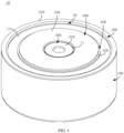
FIG.1 is a perspective view of a battery according to an embodiment. -
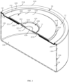
FIG. 2 is a perspective cross-sectional view of the battery shown inFIG. 1 ; -
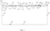
FIG. 3 is a plan cross-sectional view of the battery shown inFIG. 1 ; -
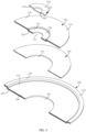
FIG. 4 is an exploded view of the battery shown inFIG. 1 ; -
FIG. 5 is a perspective partial cross-sectional view ofFIG. 4 ; -
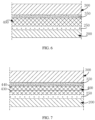
FIG. 6 is a plan partial cross-sectional view of a cover assembly of the battery shown inFIG. 1 according to a first example; -
FIG. 7 is a plan partial cross-sectional view of the cover assembly of the battery shown inFIG. 1 according to a second example; -
FIG. 8 is a flowchart of a cover assembly processing method according to an embodiment. - In order to facilitate the understanding of the present disclosure, the present disclosure will be described more completely hereinafter with reference to the related accompanying drawings. Preferable embodiments of the present disclosure are presented in the accompanying drawings. However, the present disclosure may be embodied in many different forms and is not limited to the embodiments described herein. Rather, these embodiments are provided so that the understanding of the disclosure of the present disclosure will be more thorough and complete.
- It should be understood that when an element is defined as "fixed to" another element, it is either directly on an element or indirectly on an element with a mediating element. When an element is considered to be "connected" to another element, it can be directly connected to another element or indirectly connected to another element with a mediating element. The terms "in", "out", "left", "right" and similar expressions used herein are for illustrative purposes only and are not meant to be the only implementation.
- Referring to
FIGS. 1 ,2 and3 , abattery 10 provided by an embodiment includes ahousing 100, acover assembly 20, and a rolling core assembly (not shown). Thecover assembly 20 includes atop cover 200, ananode piece 300, aninsulating piece 400, and asealing member 500. - Referring to
FIGS. 3 ,4 and5 , in some embodiments, thehousing 100 may be made of stainless steel. Thehousing 100 may have a cylinder-shaped structure. Thehousing 100 may enclose anaccommodating cavity 110, which is a space having an opening. When thehousing 100 is independently present, theaccommodating cavity 110 is in direct communication with the outside through the opening. In other embodiments, thehousing 100 may also have a shape of prismatic, such as a quadrangular or hexagonal prism, or the like. Thehousing 100 has an inner sideperipheral surface 120 and aninner bottom surface 130. Theinner bottom surface 130 may be a horizontally arranged circular surface, the inner sideperipheral surface 120 may be a vertically arranged annular surface, and a lower end of the inner sideperipheral surface 120 is connected to a periphery of theinner bottom surface 130, such that the inner sideperipheral surface 120 is disposed around theinner bottom surface 130. The inner sideperipheral surface 120 and theinner bottom surface 130 cooperatively define a boundary of theaccommodating cavity 110. When thehousing 100 has a shape of cylinder, an outer diameter of thehousing 100 may be, for example, 12.2 mm. - The rolling core assembly is accommodated in the
accommodating cavity 110, and an electrolyte is stored in the rolling core assembly. When theaccommodating cavity 110 is larger, a volume of the rolling core assembly may be larger, such that an amount of power stored by the battery 10a is larger, thereby increasing the capacity of the entire battery 10a and the endurance of the battery 10a. To the contrary, when theaccommodating cavity 110 is smaller, the volume of the rolling core assembly is smaller, such that the amount of power stored by the battery 10a is smaller, thereby decreasing the capacity of the entire battery 10a and the endurance of the battery 10a. In short, a volume size of theaccommodating cavity 110 is proportional to the capacity and endurance of thebattery 10. An anode tab strip and a cathode tab strip can be provided on the rolling core assembly. One end of the cathode tab strip is connected to the rolling core assembly, and the other end of the cathode tab strip is welded to thehousing 100, such that it can be understood that thehousing 100 can be understood as a cathode of the battery. - In some embodiments, a descending
platform 121 is provided on thehousing 100. Specifically, the descendingplatform 121 is formed by an upper end of the innerperipheral surface 120 adjacent the opening. Taking a central axis of thehousing 100 as a reference, when thehousing 100 has a shape of cylinder, a direction perpendicular to the central axis can be understood as a radial direction of thehousing 100, and the upper end of the innerperipheral surface 120 is recessed along the radial direction of thehousing 100 for a set depth to form the descendingplatform 121. By forming the descendingplatform 121, the volume of theaccommodating cavity 110 can be reasonably increased on the basis of ensuring that thehousing 100 has sufficient structural strength, such that the capacity and the endurance of thebattery 10 can be increased to a certain extent. - Referring to
FIGS. 3 ,4 and5 , in some embodiments, thetop cover 200 is substantially circular in shape and may be made of stainless steel. Thetop cover 200 is connected to thehousing 100, that is, an edge of thetop cover 200 is connected to an upper end of thehousing 100, such that thetop cover 200 can seal the opening of theaccommodating cavity 110. Thetop cover 200 and thehousing 100 can be directly connected by welding, such that a structure of thetop cover 200 can be simplified, and a connection strength between thetop cover 200 and thehousing 100 can be increased. Thetop cover 200 has anouter side surface 260 located outside theaccommodating cavity 110, and thehousing 100 has an outer sideperipheral surface 140 located outside theaccommodating cavity 110, and theouter side surface 260 and the outer sideperipheral surface 140 may be coplanar with each other. - The
top cover 200 also has atop surface 230 away from theaccommodating cavity 110. The central portion of thetop surface 230 is formed with acounterbore 231 that is recessed towards theaccommodating cavity 110 by a set depth. Thecounterbore 231 is configured to accommodate theanode piece 300. A recessed depth of thecounterbore 231 may be about 0.25 mm, for example, it may be from 0.20 mm to 0.30 mm, and more specifically, it may be 0.20 mm, 0.22 mm, 0.25 mm, or 0.30 mm. - The structure of the
top cover 200 can also be described in the following manner. Thetop cover 200 includes asubstrate portion 210 and a recessedportion 220, and thesubstrate portion 210 surrounds an edge of the recessedportion 220. Thetop surface 230 is disposed on thesubstrate portion 210, and the recessedportion 220 is recessed downward towards theinner bottom surface 130 relative to thesubstrate portion 210. In short, the recessedportion 220 is recessed downward by a certain length relative to thesubstrate portion 210. Both thesubstrate portion 210 and the recessedportion 220 cooperatively enclose theaforementioned counterbore 231. An edge of thesubstrate portion 210 away from the recessedportion 220 is welded to thehousing 100. The recessedportion 220 is accommodated in theaccommodating cavity 110. Along the radial direction of thehousing 100, acertain gap 12 is formed between the recessedportion 220 and the inner sideperipheral surface 120. By providing thegap 12, the recessedportion 220 can occupy as little space of theaccommodating cavity 110 as possible, thereby ensuring that theaccommodating cavity 110 has a sufficient volume to improve the capacity and endurance of thebattery 10. An outer diameter of thesubstrate portion 210 may be approximately equivalent to an outer diameter of thehousing 100. A thickness of thesubstrate portion 210 may be about 0.15 mm. A dimension occupied by the entiretop cover 200 in a thickness direction of thebattery 10 may be about 0.4 mm, which can be understood as a sum of the thickness of thesubstrate portion 210 and a thickness of the recessedportion 220 is about 0.4 mm. An outer diameter of the recessedportion 220 may be approximately 91% of an outer diameter of the entiretop cover 200. - Since the
top cover 200 is recessed and formed with thecounterbore 231, thetop cover 200 may have alower bottom surface 240. Thelower bottom surface 240 is a horizontally arranged circular surface. Thelower bottom surface 240 may be parallel to aninner bottom surface 130 of thehousing 100 and define part of a boundary of thecounterbore 231. Thelower bottom surface 240 is located in the middle of the recessedportion 220. A middle portion of thelower bottom surface 240 is formed with a throughhole 241 extending through the entiretop cover 200, such that a lower end of the throughhole 241 is in communication with theaccommodating cavity 110 and an upper end of the throughhole 241 is in communication with thecounterbore 231. The throughhole 241 is formed on the recessedportion 220. When the entiretop cover 200 is welded to thehousing 100, an electrolyte may be injected into theaccommodating cavity 110 through the throughhole 241, such that the electrolyte is stored in the rolling core assembly. The recessedportion 220 also has afirst surface 221 disposed opposite to the orientation of thelower bottom surface 240, that is, thefirst surface 221 is arranged facing theaccommodating cavity 110. The throughhole 241 extends through thefirst surface 221, and thefirst surface 221 is farthest from thetop surface 230 relative to the other surfaces of thetop cover 200 in a thickness direction of the entire battery. - Referring to
FIGS. 3 ,4 , and5 , in some embodiments, the insulatingpiece 400 may be made of a non-metallic insulator material, for example, the insulatingpiece 400 may be made of a polypropylene (PP) material. The insulatingpiece 400 is provided with a mountinghole 410 formed in the middle of the insulatingpiece 400, and the mountinghole 410 extends through the entire insulatingpiece 400 in a thickness direction of the insulatingpiece 400. Thus, the insulatingpiece 400 has a substantially annular structure. A diameter of the mountinghole 410 may be appropriately less than a diameter of the throughhole 241 on thetop cover 200. The insulatingpiece 400 is stacked between theanode piece 300 and thetop cover 200, such that the insulatingpiece 400 is connected to theanode piece 300 and thetop cover 200, for example, the insulatingpiece 400 may be connected to thetop cover 200 by hot-melting, and the insulatingpiece 400 may be connected to theanode piece 300 by hot-melting. A thickness of the insulatingpiece 400 may be approximately from 0.05 mm to 0.15 mm, for example, a specific value of the thickness of the insulatingpiece 400 may be 0.05 mm, 0.09 mm, 0.1 mm, 0.15 mm, or the like. The insulatingpiece 400 is accommodated in thecounterbore 231 of thetop cover 200, and a thickness of the insulatingpiece 400 is less than the recessed depth of thecounterbore 231, such that the upper surface of the insulatingpiece 400 is located below thetop surface 230, thereby preventing the upper surface of the insulatingpiece 400 and thetop surface 230 of thetop cover 200 from being coplanar with each other. Since the insulatingpiece 400 is accommodated in thecounterbore 231 of thetop cover 200, the insulatingpiece 400 can make full use of the existing space of thecounterbore 231, such that the insulatingpiece 400 does not need to occupy the mounting space outside thecounterbore 231, and the arrangement of the insulatingpiece 400 does not increase an overall thickness dimension of the entire battery. - Referring to
FIGS. 3 ,4 , and5 , in some embodiments, theanode piece 300 is substantially shaped as an annular and made of stainless steel. Theanode piece 300 is disposed on thetop cover 200 via the insulatingpiece 400. One end of the anode tab strip is connected to the rolling core assembly, and the other end of the anode tab strip is welded to theanode piece 300, such that theanode piece 300 can be understood as the anode of thebattery 10. Theanode piece 300 is partially accommodated in thecounterbore 231. Theanode piece 300 has anupper surface 330 away from theaccommodating cavity 110, that is, theupper surface 330 is away from theinner bottom surface 130 of thehousing 100. Theupper surface 330 is recessed downward towards theaccommodating cavity 110 to form a recessedhole 331. Theupper surface 330 of theanode piece 300 may be parallel to thetop surface 230 of thetop cover 200. Theupper surface 330 of theanode piece 300 may be spaced apart from thetop surface 230 of thetop cover 200 in a thickness direction of the battery, that is, theupper surface 330 is located below thetop surface 230, such that theupper surface 330 is closer to theaccommodating cavity 110 with respect to thetop surface 230, that is, theupper surface 330 is closer to thelower bottom surface 240 with respect to thetop surface 230, or it may be understood that theupper surface 330 does not protrude upward from thetop surface 230. Theanode piece 300 includes abottom plate portion 310 and a descendingportion 320. Thebottom plate portion 310 and the descendingportion 320 are connected to each other, that is, thebottom plate portion 310 is connected around an edge of the descendingportion 320, and the descendingportion 320 is provided protruding downward towards theinner bottom surface 130 relative to thebottom plate portion 310. In short, the descendingportion 320 protrudes downward for a certain length relative to thebottom plate portion 310, and both thebottom plate portion 310 and the descendingportion 320 cooperatively enclose the recessedhole 331. - Due to the presence of the recessed
hole 331 in theanode piece 300, theanode piece 300 may have abottom wall surface 340. Thebottom wall surface 340 is a circular surface horizontally disposed, and thebottom wall surface 340 may be disposed parallel to theinner bottom surface 130 of thehousing 100 and define part of the boundary of the recessedhole 331. Thebottom wall surface 340 is located at the descendingportion 320 and away from theaccommodating cavity 110. Anpenetration hole 341 is formed in a middle portion of thebottom wall surface 340, which extends through theentire anode piece 300 in a thickness direction of theanode piece 300, such that the lower end of thepenetration hole 341 is in communication with theaccommodating cavity 110 through the throughhole 241, and the upper end of the throughhole 241 is in communication with the recessedhole 331. Thepenetration hole 341 is formed in the descendingportion 320. When theanode piece 300 is fixed to thetop cover 200 via the insulatingpiece 400, the electrolyte can be injected into theaccommodating cavity 110 through thepenetration hole 341. The descendingportion 320 also has asecond surface 321 facing theaccommodating cavity 110, that is, the orientations of thesecond surface 321 and thebottom wall surface 340 are opposite. Thepenetration hole 341 extends through thesecond surface 321. Thesecond surface 321 is farthest from thetop surface 330 relative to the other surfaces of theanode piece 300 in a thickness direction of the entire battery. The anode tab strip on the rolling core assembly is welded to thesecond surface 321 via the throughhole 241, then thefirst surface 221 and thesecond surface 321 may be coplanar with each other. In this way, an end of thefirst surface 221 is prevented from scratching the anode tab strip, and the insulating material on the anode tab strip is effectively prevented from being damaged. In other embodiments, thefirst surface 221 and thesecond surface 321 may be separated from each other by a smaller distance in a vertical direction, for example, thefirst surface 221 is further away from thetop surface 230 with respect to thesecond surface 321. - The
bottom plate portion 310 is connected to the insulatingpiece 400 by hot melting, and thebottom plate portion 310 is located in thecounterbore 231 of thetop cover 200. Theupper surface 330 is located on thebottom plate portion 310, and thebottom plate portion 310 is stacked on the insulatingpiece 400. Since theupper surface 330 of thebottom plate portion 310 is located below thetop surface 230 or just coplanar with thetop surface 230, thebottom plate portion 310 can make full use of the existing space of thecounterbore 231, such that thebottom plate portion 310 does not need to occupy the mounting space outside thecounterbore 231, and the arrangement of thebottom plate portion 310 does not increase an overall thickness dimension of the entire battery. The descendingportion 320 may be accommodated in the mountinghole 410 of the insulatingpiece 400 and the throughhole 241 of thetop cover 200. In this way, the descendingportion 320 can make full use of the existing space of the mountinghole 410 and the throughhole 241, so as to ensure that the descendingportion 320 does not increase a total thickness dimension of theentire battery 10, thereby ensuring that the arrangement of theentire anode piece 300 does not increase the thickness dimension of theentire battery 10. - Referring to
FIGS. 6 and 7 , specifically, thetop cover 200 includes afirst connection layer 250 having a molecular structure different from other portions of thetop cover 200. Theanode piece 300 includes asecond connection layer 350 having a molecular structure different from other portions of theanode piece 300. The insulatingpiece 400 is stacked between thefirst connection layer 250 and thesecond connection layer 350, and the insulatingpiece 400 is connected to thefirst connection layer 250 and thesecond connection layer 350 by hot-melting, such that the entiretop cover 200 and theanode piece 300 are finally connected via the insulatingpiece 400 by hot-melting. During the hot-melt connection of thefirst connection layer 250 and thesecond connection layer 350 via the insulatingpiece 400, the insulatingpiece 400 may be divided into two parts of equal thickness, which may be denoted as a first insulating portion 430 and a second insulatingportion 440, respectively. First, the first insulating portion 430 may be connected to thefirst connection layer 250 by a hot-melt process. Then, the second insulatingportion 440 is connected to thesecond connection layer 350 by the hot-melt process, and finally, the first insulating portion and the second insulatingportion 440 are connected to each other by hot-melting. In this way, an integral connection relationship between the entire insulatingpiece 400 and theanode piece 300, and between the entire insulatingpiece 400 and thetop cover 200 can be realized. When the first insulating portion and the second insulatingportion 440 are connected to each other by hot-melting, the first insulating portion and the second insulatingportion 440 are fused to form an integral insulatingpiece 400. - In some embodiments, the insulating
piece 400 may be formed as an inseparable entirety. For example, after the insulatingpiece 400 is connected to thefirst connection layer 250 by hot-melting, the insulatingpiece 400 is connected to thesecond connection layer 350 by hot-melting, such that thetop cover 200 and theanode piece 300 are connected via the insulatingpiece 400 by hot-melting. For another example, after the insulatingpiece 400 is connected on thesecond connection layer 350 by hot-melting, the insulatingpiece 400 is connected on thefirst connection layer 250 by hot-melting, such that thetop cover 200 and theanode piece 300 are connected via the insulatingpiece 400 by hot-melting. - In the hot-melt connection process, the insulating
piece 400 is heated such that a part of the insulatingpiece 400 is melted into a viscous shape, and then the viscous part is attached to thetop cover 200 or theanode piece 300. After the viscous part is solidified and formed, the insulatingpiece 400 is connected to thetop cover 200 or theanode piece 300 by hot-melting. - The cross-sectional dimensions of both the insulating
piece 400 and theanode piece 300 are less than the cross-sectional dimension of thetop cover 200, such that the orthographic projection of both the insulatingpiece 400 and theanode piece 300 in a thickness direction of thetop cover 200 is located within the recessedportion 220, such that edges of thebase plate portion 310 and the insulatingpiece 400 may be spaced apart from thesubstrate portion 210 to form agap 13 in the radial direction of thehousing 100. This effectively prevents the edge ofanode piece 300 from being in contact with thetop cover 200 and causing a short circuit. - Due to the hot-melt connection between the insulating
piece 400 and thetop cover 200, and between the insulatingpiece 400 and theanode piece 300, on one hand, other additional connection layers between the insulatingpiece 400 and thetop cover 200 are effectively avoided, and on the other hand, other additional connection layers between the insulatingpiece 400 and theanode piece 300 are avoided, thereby effectively simplifying the structure of theentire cover assembly 20 and reducing a total thickness thereof. On the other hand, the insulatingpiece 400 is stacked between thefirst connection layer 250 and thesecond connection layer 350 and connected to each other by hot-melting, such that a possible gap between the insulatingpiece 400 and thetop cover 200, and between the insulatingpiece 400 and theanode piece 300 can be completely eliminated, thereby improving the sealing performance of the insulatingpiece 400 to theentire battery 10. - Since the
housing 100 serves as the cathode of the battery 10a, and thetop cover 200 is welded to thehousing 100, both thetop cover 200 and thehousing 100 can serve as the cathode of the battery 10a, and theanode piece 300 serves as the anode of the battery 10a. By providing the insulatingpiece 400, on the one hand, theanode piece 300 and thetop cover 200 can be insulated, and the short circuit phenomenon caused by the electrical conduction between theanode piece 300 and thetop cover 200 can be prevented. The insulatingpiece 400 has an exposedportion 420, and when the insulatingpiece 400 is connected to thebottom plate portion 310, the exposedportion 420 surrounds theanode piece 300 and is located outside the coverage area of theanode piece 300. By providing the exposedportion 420, other conductors can be further prevented from connecting theanode piece 300 and thetop cover 200, thus further enhancing the blocking and insulating effect of the insulatingpiece 400, and minimizing the short circuit phenomenon of the battery. On the other hand, the insulatingpiece 400 is stacked between thefirst connection layer 250 and thesecond connection layer 350 and connected to each other by hot-melting, such that the gap between thebottom plate portion 310 and thetop cover 200 can be completely eliminated, and the electrolyte in the rolling core assembly can be prevented from flowing out of theaccommodating cavity 110 through the gap between thebottom plate portion 310 and thetop cover 200, that is, the electrolyte can be effectively prevented from leaking, that is, the insulatingpiece 400 can also play a good sealing role. - Referring to
FIGS. 3 ,4 , and5 , in some embodiments, the sealingmember 500 has abase portion 510 and aboss portion 520. Thebase portion 510 is connected around the edge of theboss portion 520, and theboss portion 520 protrudes downward towards theinner bottom surface 130 relative to thebase portion 510. In short, theboss portion 520 protrudes downward for a certain length with respect to thebase portion 510. Thebase portion 510 has anouter surface 530 away from theaccommodating cavity 110, that is, theouter surface 530 faces away from theinner bottom surface 130. Theouter surface 530 may be coplanar with theupper surface 330. Alternatively, theouter surface 530 is closer to theaccommodating cavity 110 with respect to theupper surface 330, that is, theouter surface 530 is located below theupper surface 330. In the radial direction of thehousing 100, that is, in a direction perpendicular to the central axis of thehousing 100, agap 11 is formed between an edge of thebase portion 510 and thebottom plate portion 310 of theanode piece 300. - Since the
base portion 510 is located in the recessedhole 331 and theouter surface 530 is located below theupper surface 330, thebase portion 510 makes full use of the existing space of the recessedhole 331, such that thebase portion 510 does not need to occupy the mounting space outside the recessedhole 331, and the arrangement of thebase portion 510 does not increase the overall thickness dimension of the entire battery. Meanwhile, theboss portion 520 is accommodated in thepenetration hole 341, such that theboss portion 520 makes full use of the existing space of thepenetration hole 341, and ensures that theboss portion 520 does not increase the overall thickness dimension of the entire battery. This ensures that the arrangement of theentire sealing member 500 does not increase the thickness dimension of the entire battery. - The sealing
member 500 may be made of stainless steel. The sealingmember 500 is welded to theanode piece 300 and serves to block thepenetration hole 341. After the electrolyte is injected into theaccommodating cavity 110 from thepenetration hole 341 through the throughhole 241, the sealingmember 500 may be welded to theanode piece 300, such that theboss portion 520 seals thepenetration hole 341, and the electrolyte in theaccommodating cavity 110 is prevented from leaking out of theaccommodating cavity 110 through thepenetration hole 341, that is, the electrolyte is effectively prevented from leaking. - If the
anode piece 300, the insulatingpiece 400, and thetop cover 200 are sequentially stacked in the thickness direction of thebattery 10, a sum of the respective thicknesses of theanode piece 300, the insulatingpiece 400, and thetop cover 200 will constitute part of the thickness of thebattery 10, that is, the arrangement of any one of theanode piece 300, the insulatingpiece 400, and thetop cover 200 will increase the thickness of thebattery 10, thereby increasing the thickness of thebattery 10, which is not conducive to reducing the volume of thebattery 10 to achieve miniaturization. - In the aforementioned embodiment, by providing the
counterbore 231 on thetop cover 200, the insulatingpiece 400 and theanode piece 300 are accommodated in thecounterbore 231, and theupper surface 330 is coplanar with thetop surface 230, or theupper surface 330 is located below thetop surface 230, such that the thicknesses of the insulatingpiece 400 and theanode piece 300 do not increase the thickness of thebattery 10, thereby compressing the thickness of thebattery 10 and reducing the volume of thebattery 10 to achieve miniaturization. At the same time, the influence of the aforementioned structure arrangement on the volume of theaccommodating cavity 110 is negligible, so as to ensure that theaccommodating cavity 110 has a large enough volume to ensure that thebattery 10 has a reasonable capacity and endurance, and finally ensure that thebattery 10 can take into account the two core parameters of large capacity and small volume at the same time, and the improvement of one parameter will not be at the expense of the other parameter. - Further, if the insulating
piece 400 is press-fitted into thetop cover 200 and theanode piece 300 to form a detachable split connection manner, in order to improve the connection strength, theanode piece 300 must be formed into a "cap" structure to cover the entiretop cover 200 and cover thehousing 100, such that the thickness of theanode piece 300 constitutes part of the thickness of the battery, that is, the presence of theanode piece 300 will increase the thickness of the battery, and on the other hand, the surface area and the volume of theanode piece 300 will increase, resulting in an increase in the material cost, while increasing the volume of the battery. - In the aforementioned embodiment, the insulating
piece 400 is integrally connected to thetop cover 200 and theanode piece 300 by hot-melt connection, such that theanode piece 300 can be effectively prevented from covering the entiretop cover 200, and an advantageous condition is created for providing thecounterbore 231 on thetop cover 200, so as to ensure that theanode piece 300 is accommodated in thecounterbore 231 of thetop cover 200. On the one hand, the presence of theanode piece 300 does not increase the thickness of thebattery 200, on the other hand, the surface area and the volume of the insulatingpiece 400 and theanode piece 300 are reduced, and the material cost is reduced. Finally, the volume of thebattery 10 is reduced and its manufacturing cost is reduced. - Referring to
FIG. 8 , according to an embodiment, a cover assembly processing method for processing theaforementioned cover assembly 20 is provided, the processing method mainly includes the following steps: - Step S610, the
top cover 200 is chemically treated to form afirst connection layer 250 having a molecular structure different from other portions. - Step S620, the
anode piece 300 is chemically treated to form asecond connection layer 350 having a molecular structure different from other portions. - Step S630, the insulating
piece 400 is connected to thefirst connection layer 250 and thesecond connection layer 350 by hot-melting. - Referring to
FIGS. 6, 7 and8 , specifically, thetop cover 200 and theanode piece 300 are chemically treated by a chemical liquid including a passivation liquid having a certain acid such that afirst connection layer 250 including a passivation layer is formed on thetop cover 200 and asecond connection layer 350 including a passivation layer is formed on theanode piece 300. Since both thefirst connection layer 250 and thesecond connection layer 350 include passivation layers, thefirst connection layer 250 has a relatively dense molecular structure relative to other portions of thetop cover 200, and thesecond connection layer 350 also has a relatively dense molecular structure relative to other portions of theanode piece 300. After the aforementioned chemical treatment, the oil stain on thetop cover 200 and theanode piece 300 can be removed, and the corrosion resistance of thefirst connection layer 250 and thesecond connection layer 350 can be improved, and the connection strength between thefirst connection layer 250 and the insulatingpiece 400, and the connection strength between thesecond connection layer 350 and the insulatingpiece 400 can be further improved. Thefirst connection layer 250 is integrally connected to the other portions of thetop cover 200, and thesecond connection layer 350 is integrally connected to the other portions of theanode piece 300. After heating the part of the insulatingpiece 400 connected to thefirst connection layer 250 to be viscous, the viscous part is solidified to form a hot-melt connection having a high connection strength with thefirst connection layer 250. After heating a part of the insulating piece connected to thesecond connection layer 350 to be viscous, the viscous part is solidified to form a hot-melt connection having a high connection strength with thesecond connection layer 350. - Referring to
FIG. 6 , in some embodiments, the insulatingpiece 400 is formed into an inseparable entirety. After the insulatingpiece 400 is connected to thefirst connection layer 250 by hot-melting, the insulatingpiece 400 is connected to thesecond connection layer 350 by hot-melting; or after the insulatingpiece 400 is connected to thesecond connection layer 350 by hot-melting, the insulatingpiece 400 is connected to thefirst connection layer 250 by hot-melting. Finally, thefirst connection layer 250 and thesecond connection layer 350 are connected via the insulating piece by hot-melting. - Referring to
FIG. 7 , in some embodiments, the insulatingpiece 400 is divided into a first insulating portion 430 and a second insulatingportion 440 having equal thicknesses. The first insulating portion 430 is connected to thefirst connection layer 250 by hot-melting, the second insulatingportion 440 is connected to thesecond connection layer 350 by hot-melting, and finally the first insulating portion 430 and the second insulatingportion 440 are connected by hot-melting, such that thefirst connection layer 250 and thesecond connection layer 350 can be connected via the insulating piece by hot-melting. - In some embodiments, the roughness of the
first connection layer 250 and thesecond connection layer 350 may be increased by sandblasting, which making, for example, the roughness of the connection part between thefirst connection layer 250 and the insulatingpiece 400, and the roughness of the connection part between thesecond connection layer 350 and the insulatingpiece 400 are maintained between 0.8µm and 6.3µm. In this way, the connection force between the insulatingpiece 400 and thefirst connection layer 250, and the connection force between the insulatingpiece 400 andsecond connection layer 350 can be effectively increased.
Claims (12)
- A cover assembly (20) adapted for a battery (10a) whose housing (100) having an accommodating cavity (110), the cover assembly (20) comprising:a top cover (200) connected to the housing (100) and covering the accommodating cavity (110), the top cover (200) having a top surface (230) away from the accommodating cavity (110), and the top surface (230) being recessed towards the accommodating cavity (110) to form a counterbore (231); andan anode piece (300) provided on the top cover (200) and accommodated in the counterbore (231), the anode piece (300) having an upper surface (330) away from the accommodating cavity (110), and the upper surface (330) being coplanar with the top surface (230); or the upper surface (330) being closer to the accommodating cavity (110) with respect to the top surface (230).
- The cover assembly (20) according to claim 1, wherein the top cover (200) comprises a substrate portion (210) and a recessed portion (220), the top surface (230) is located on the substrate portion (210), the recessed portion (220) protrudes from the substrate portion (210), and the substrate portion (210) and the recessed portion (220) cooperatively enclose the counterbore (231).
- The cover assembly (20) according to claim 1, wherein the top cover (200) is provided with a through hole (241) in communication with the counterbore (231) and through which liquid is injected into the accommodating cavity (110), the anode piece (300) comprises a bottom plate portion (310) and a descending portion (320) protruding from the bottom plate portion (310), the bottom plate portion (310) is accommodated in the counterbore (231), and the descending portion (320) is accommodated in the through hole (241).
- The cover assembly (20) according to claim 3, wherein in a thickness direction of the cover assembly (20), the top cover (200) has a first surface (221) farthest from the top surface (230), the descending portion (320) has a second surface (321) farthest from the upper surface (330), and the first surface (221) is coplanar with the second surface (321).
- The cover assembly (20) according to claim 1, further comprising a sealing member (500) connected to the anode piece (300), wherein the upper surface (330) of the anode piece (300) is recessed to form a recessed hole (331), the anode piece (300) has a bottom wall surface (340) defining part of a boundary of the recessed hole (331), the bottom wall surface (340) is provided with a penetration hole (341) through which liquid is injected into the accommodating cavity (110), the sealing member(500) is capable of sealing the penetration hole (341) and has an outer surface (530) away from the accommodating cavity (110), and the outer surface (530) is coplanar with the upper surface (330); or the outer surface (530) is closer to the accommodating cavity (110) with respect to the upper surface (330).
- The cover assembly (20) according to claim 5, wherein the sealing member(500) has a base portion (510) and a boss portion (520) protruding from the base portion (510), the base portion (510) is accommodated in the recessed hole (331), the boss portion (520) is accommodated in the penetration hole (341), and the outer surface (530) is located on the base portion (510).
- The cover assembly (20) according to claim 6, wherein a gap is form between the base portion (510) and the anode piece (300) in a direction perpendicular to a central axis of the housing (100).
- The cover assembly (20) according to claim 5, wherein the anode piece (300) is welded to the sealing member (500).
- The cover assembly (20) according to claim 1, wherein a recessed depth of the counterbore (231) is from 0.20 mm to 0.30 mm.
- The cover assembly (20) according to claim 1, wherein the housing (100), the top cover (200), and the anode piece (300) are made of stainless steel.
- The cover assembly (20) according to claim 1, wherein the top cover (200) is welded to the housing (100).
- A battery (10a), comprising a housing (100) and the cover assembly (20) according to any one of claims 1 to 11, wherein the housing (100) is provided with the accommodating cavity (110), the top cover (200) is connected to the housing (100) and covers the accommodating cavity (110).
Applications Claiming Priority (1)
| Application Number | Priority Date | Filing Date | Title |
|---|---|---|---|
| CN202111170221.XA CN113764790A (en) | 2021-10-08 | 2021-10-08 | Covering assembly and battery |
Publications (1)
| Publication Number | Publication Date |
|---|---|
| EP4164013A1 true EP4164013A1 (en) | 2023-04-12 |
Family
ID=78798928
Family Applications (1)
| Application Number | Title | Priority Date | Filing Date |
|---|---|---|---|
| EP21214170.9A Pending EP4164013A1 (en) | 2021-10-08 | 2021-12-13 | Cover assembly and battery |
Country Status (5)
| Country | Link |
|---|---|
| US (1) | US20240213595A1 (en) |
| EP (1) | EP4164013A1 (en) |
| JP (1) | JP2023548988A (en) |
| CN (1) | CN113764790A (en) |
| WO (1) | WO2023056664A1 (en) |
Citations (2)
| Publication number | Priority date | Publication date | Assignee | Title |
|---|---|---|---|---|
| CN212434722U (en) * | 2020-06-03 | 2021-01-29 | 珠海冠宇电池股份有限公司 | Button cell and electronic equipment |
| CN113437410A (en) * | 2020-08-04 | 2021-09-24 | 珠海冠宇电池股份有限公司 | Button cell and preparation method thereof |
Family Cites Families (9)
| Publication number | Priority date | Publication date | Assignee | Title |
|---|---|---|---|---|
| CN102339958B (en) * | 2010-07-23 | 2014-05-28 | 松下能源(无锡)有限公司 | Seal plate assembly for battery and battery having the same |
| KR20210021841A (en) * | 2019-08-19 | 2021-03-02 | 삼성에스디아이 주식회사 | Rechargeable battery |
| CN115104216A (en) * | 2020-02-12 | 2022-09-23 | 株式会社村田制作所 | Secondary battery |
| WO2021185074A1 (en) * | 2020-03-18 | 2021-09-23 | 珠海冠宇电池股份有限公司 | Battery casing, battery and electronic device |
| WO2022109939A1 (en) * | 2020-11-26 | 2022-06-02 | 宁德新能源科技有限公司 | Electrochemical apparatus and electronic device |
| CN213520130U (en) * | 2020-12-04 | 2021-06-22 | 珠海冠宇电池股份有限公司 | Button cell and electronic equipment |
| CN213989143U (en) * | 2020-12-14 | 2021-08-17 | 厦门海辰新能源科技有限公司 | Annotate liquid hole seal structure and power battery top cap |
| CN213989125U (en) * | 2020-12-22 | 2021-08-17 | 厦门海辰新能源科技有限公司 | Lithium ion battery structure |
| CN216015527U (en) * | 2021-10-08 | 2022-03-11 | 深圳市聚和源科技有限公司 | Covering assembly and battery |
-
2021
- 2021-10-08 CN CN202111170221.XA patent/CN113764790A/en active Pending
- 2021-10-21 US US17/802,469 patent/US20240213595A1/en active Pending
- 2021-10-21 WO PCT/CN2021/125175 patent/WO2023056664A1/en active Application Filing
- 2021-10-21 JP JP2022502506A patent/JP2023548988A/en active Pending
- 2021-12-13 EP EP21214170.9A patent/EP4164013A1/en active Pending
Patent Citations (2)
| Publication number | Priority date | Publication date | Assignee | Title |
|---|---|---|---|---|
| CN212434722U (en) * | 2020-06-03 | 2021-01-29 | 珠海冠宇电池股份有限公司 | Button cell and electronic equipment |
| CN113437410A (en) * | 2020-08-04 | 2021-09-24 | 珠海冠宇电池股份有限公司 | Button cell and preparation method thereof |
Also Published As
| Publication number | Publication date |
|---|---|
| WO2023056664A1 (en) | 2023-04-13 |
| US20240213595A1 (en) | 2024-06-27 |
| CN113764790A (en) | 2021-12-07 |
| JP2023548988A (en) | 2023-11-22 |
Similar Documents
| Publication | Publication Date | Title |
|---|---|---|
| EP1705732B1 (en) | Lithium secondary battery | |
| JP5204041B2 (en) | Secondary battery | |
| KR100478100B1 (en) | Square battery | |
| JP4499648B2 (en) | Lithium ion secondary battery | |
| KR100709873B1 (en) | Secondary battery | |
| US9318732B2 (en) | Lithium rechargeable battery | |
| KR100458437B1 (en) | Sealed battery | |
| JP2004146362A (en) | Cap assembly, secondary battery comprising the same, and method of manufacturing cap assembly | |
| KR20000019349A (en) | Cap assembly of secondary cell | |
| KR20030040136A (en) | Sealed battery | |
| US20230126021A1 (en) | Battery | |
| JP5240824B2 (en) | Sealed battery | |
| KR20140008236A (en) | Secondary battery | |
| EP4164013A1 (en) | Cover assembly and battery | |
| CN219626763U (en) | Lower plastic assembly, battery top cover and secondary battery | |
| CN112234282A (en) | Battery shell assembly, battery and preparation method | |
| CN115485924A (en) | Battery and electric device with same | |
| EP4164033A1 (en) | Cover assembly, method of processing the same, and battery | |
| CN216015527U (en) | Covering assembly and battery | |
| CN213304244U (en) | Battery shell assembly and battery | |
| KR20040035411A (en) | Prismatic type lithium secondary battery and the fabrication method of the same | |
| KR20230026521A (en) | Battery and electronic device having the battery | |
| CN211455874U (en) | Battery with a battery cell | |
| CN219497876U (en) | Button cell and electronic product | |
| CN216288827U (en) | Hard shell lithium ion battery |
Legal Events
| Date | Code | Title | Description |
|---|---|---|---|
| PUAI | Public reference made under article 153(3) epc to a published international application that has entered the european phase |
Free format text: ORIGINAL CODE: 0009012 |
|
| STAA | Information on the status of an ep patent application or granted ep patent |
Free format text: STATUS: REQUEST FOR EXAMINATION WAS MADE |
|
| 17P | Request for examination filed |
Effective date: 20220927 |
|
| AK | Designated contracting states |
Kind code of ref document: A1 Designated state(s): AL AT BE BG CH CY CZ DE DK EE ES FI FR GB GR HR HU IE IS IT LI LT LU LV MC MK MT NL NO PL PT RO RS SE SI SK SM TR |
|
| P01 | Opt-out of the competence of the unified patent court (upc) registered |
Effective date: 20230530 |