EP4164006A1 - Sulfide solid electrolyte, all solid state battery, and method for producing sulfide solid electrolyte - Google Patents
Sulfide solid electrolyte, all solid state battery, and method for producing sulfide solid electrolyte Download PDFInfo
- Publication number
- EP4164006A1 EP4164006A1 EP22199832.1A EP22199832A EP4164006A1 EP 4164006 A1 EP4164006 A1 EP 4164006A1 EP 22199832 A EP22199832 A EP 22199832A EP 4164006 A1 EP4164006 A1 EP 4164006A1
- Authority
- EP
- European Patent Office
- Prior art keywords
- solid electrolyte
- sulfide solid
- gas
- active material
- sulfide
- Prior art date
- Legal status (The legal status is an assumption and is not a legal conclusion. Google has not performed a legal analysis and makes no representation as to the accuracy of the status listed.)
- Granted
Links
Images

Classifications
-
- H—ELECTRICITY
- H01—ELECTRIC ELEMENTS
- H01M—PROCESSES OR MEANS, e.g. BATTERIES, FOR THE DIRECT CONVERSION OF CHEMICAL ENERGY INTO ELECTRICAL ENERGY
- H01M10/00—Secondary cells; Manufacture thereof
- H01M10/05—Accumulators with non-aqueous electrolyte
- H01M10/056—Accumulators with non-aqueous electrolyte characterised by the materials used as electrolytes, e.g. mixed inorganic/organic electrolytes
- H01M10/0561—Accumulators with non-aqueous electrolyte characterised by the materials used as electrolytes, e.g. mixed inorganic/organic electrolytes the electrolyte being constituted of inorganic materials only
- H01M10/0562—Solid materials
-
- C—CHEMISTRY; METALLURGY
- C01—INORGANIC CHEMISTRY
- C01B—NON-METALLIC ELEMENTS; COMPOUNDS THEREOF; METALLOIDS OR COMPOUNDS THEREOF NOT COVERED BY SUBCLASS C01C
- C01B17/00—Sulfur; Compounds thereof
- C01B17/22—Alkali metal sulfides or polysulfides
-
- C—CHEMISTRY; METALLURGY
- C01—INORGANIC CHEMISTRY
- C01G—COMPOUNDS CONTAINING METALS NOT COVERED BY SUBCLASSES C01D OR C01F
- C01G17/00—Compounds of germanium
- C01G17/006—Compounds containing germanium, with or without oxygen or hydrogen, and containing two or more other elements
-
- C—CHEMISTRY; METALLURGY
- C03—GLASS; MINERAL OR SLAG WOOL
- C03C—CHEMICAL COMPOSITION OF GLASSES, GLAZES OR VITREOUS ENAMELS; SURFACE TREATMENT OF GLASS; SURFACE TREATMENT OF FIBRES OR FILAMENTS MADE FROM GLASS, MINERALS OR SLAGS; JOINING GLASS TO GLASS OR OTHER MATERIALS
- C03C10/00—Devitrified glass ceramics, i.e. glass ceramics having a crystalline phase dispersed in a glassy phase and constituting at least 50% by weight of the total composition
-
- C—CHEMISTRY; METALLURGY
- C03—GLASS; MINERAL OR SLAG WOOL
- C03C—CHEMICAL COMPOSITION OF GLASSES, GLAZES OR VITREOUS ENAMELS; SURFACE TREATMENT OF GLASS; SURFACE TREATMENT OF FIBRES OR FILAMENTS MADE FROM GLASS, MINERALS OR SLAGS; JOINING GLASS TO GLASS OR OTHER MATERIALS
- C03C3/00—Glass compositions
- C03C3/12—Silica-free oxide glass compositions
- C03C3/16—Silica-free oxide glass compositions containing phosphorus
-
- C—CHEMISTRY; METALLURGY
- C03—GLASS; MINERAL OR SLAG WOOL
- C03C—CHEMICAL COMPOSITION OF GLASSES, GLAZES OR VITREOUS ENAMELS; SURFACE TREATMENT OF GLASS; SURFACE TREATMENT OF FIBRES OR FILAMENTS MADE FROM GLASS, MINERALS OR SLAGS; JOINING GLASS TO GLASS OR OTHER MATERIALS
- C03C3/00—Glass compositions
- C03C3/32—Non-oxide glass compositions, e.g. binary or ternary halides, sulfides or nitrides of germanium, selenium or tellurium
- C03C3/321—Chalcogenide glasses, e.g. containing S, Se, Te
-
- C—CHEMISTRY; METALLURGY
- C03—GLASS; MINERAL OR SLAG WOOL
- C03C—CHEMICAL COMPOSITION OF GLASSES, GLAZES OR VITREOUS ENAMELS; SURFACE TREATMENT OF GLASS; SURFACE TREATMENT OF FIBRES OR FILAMENTS MADE FROM GLASS, MINERALS OR SLAGS; JOINING GLASS TO GLASS OR OTHER MATERIALS
- C03C4/00—Compositions for glass with special properties
- C03C4/14—Compositions for glass with special properties for electro-conductive glass
-
- C—CHEMISTRY; METALLURGY
- C04—CEMENTS; CONCRETE; ARTIFICIAL STONE; CERAMICS; REFRACTORIES
- C04B—LIME, MAGNESIA; SLAG; CEMENTS; COMPOSITIONS THEREOF, e.g. MORTARS, CONCRETE OR LIKE BUILDING MATERIALS; ARTIFICIAL STONE; CERAMICS; REFRACTORIES; TREATMENT OF NATURAL STONE
- C04B35/00—Shaped ceramic products characterised by their composition; Ceramics compositions; Processing powders of inorganic compounds preparatory to the manufacturing of ceramic products
- C04B35/515—Shaped ceramic products characterised by their composition; Ceramics compositions; Processing powders of inorganic compounds preparatory to the manufacturing of ceramic products based on non-oxide ceramics
- C04B35/547—Shaped ceramic products characterised by their composition; Ceramics compositions; Processing powders of inorganic compounds preparatory to the manufacturing of ceramic products based on non-oxide ceramics based on sulfides or selenides or tellurides
-
- H—ELECTRICITY
- H01—ELECTRIC ELEMENTS
- H01M—PROCESSES OR MEANS, e.g. BATTERIES, FOR THE DIRECT CONVERSION OF CHEMICAL ENERGY INTO ELECTRICAL ENERGY
- H01M4/00—Electrodes
- H01M4/02—Electrodes composed of, or comprising, active material
- H01M4/62—Selection of inactive substances as ingredients for active masses, e.g. binders, fillers
-
- H—ELECTRICITY
- H01—ELECTRIC ELEMENTS
- H01M—PROCESSES OR MEANS, e.g. BATTERIES, FOR THE DIRECT CONVERSION OF CHEMICAL ENERGY INTO ELECTRICAL ENERGY
- H01M4/00—Electrodes
- H01M4/02—Electrodes composed of, or comprising, active material
- H01M4/64—Carriers or collectors
- H01M4/66—Selection of materials
- H01M4/664—Ceramic materials
-
- C—CHEMISTRY; METALLURGY
- C04—CEMENTS; CONCRETE; ARTIFICIAL STONE; CERAMICS; REFRACTORIES
- C04B—LIME, MAGNESIA; SLAG; CEMENTS; COMPOSITIONS THEREOF, e.g. MORTARS, CONCRETE OR LIKE BUILDING MATERIALS; ARTIFICIAL STONE; CERAMICS; REFRACTORIES; TREATMENT OF NATURAL STONE
- C04B2235/00—Aspects relating to ceramic starting mixtures or sintered ceramic products
- C04B2235/02—Composition of constituents of the starting material or of secondary phases of the final product
- C04B2235/30—Constituents and secondary phases not being of a fibrous nature
- C04B2235/32—Metal oxides, mixed metal oxides, or oxide-forming salts thereof, e.g. carbonates, nitrates, (oxy)hydroxides, chlorides
- C04B2235/3201—Alkali metal oxides or oxide-forming salts thereof
- C04B2235/3203—Lithium oxide or oxide-forming salts thereof
-
- C—CHEMISTRY; METALLURGY
- C04—CEMENTS; CONCRETE; ARTIFICIAL STONE; CERAMICS; REFRACTORIES
- C04B—LIME, MAGNESIA; SLAG; CEMENTS; COMPOSITIONS THEREOF, e.g. MORTARS, CONCRETE OR LIKE BUILDING MATERIALS; ARTIFICIAL STONE; CERAMICS; REFRACTORIES; TREATMENT OF NATURAL STONE
- C04B2235/00—Aspects relating to ceramic starting mixtures or sintered ceramic products
- C04B2235/02—Composition of constituents of the starting material or of secondary phases of the final product
- C04B2235/30—Constituents and secondary phases not being of a fibrous nature
- C04B2235/32—Metal oxides, mixed metal oxides, or oxide-forming salts thereof, e.g. carbonates, nitrates, (oxy)hydroxides, chlorides
- C04B2235/3287—Germanium oxides, germanates or oxide forming salts thereof, e.g. copper germanate
-
- C—CHEMISTRY; METALLURGY
- C04—CEMENTS; CONCRETE; ARTIFICIAL STONE; CERAMICS; REFRACTORIES
- C04B—LIME, MAGNESIA; SLAG; CEMENTS; COMPOSITIONS THEREOF, e.g. MORTARS, CONCRETE OR LIKE BUILDING MATERIALS; ARTIFICIAL STONE; CERAMICS; REFRACTORIES; TREATMENT OF NATURAL STONE
- C04B2235/00—Aspects relating to ceramic starting mixtures or sintered ceramic products
- C04B2235/02—Composition of constituents of the starting material or of secondary phases of the final product
- C04B2235/30—Constituents and secondary phases not being of a fibrous nature
- C04B2235/36—Glass starting materials for making ceramics, e.g. silica glass
-
- C—CHEMISTRY; METALLURGY
- C04—CEMENTS; CONCRETE; ARTIFICIAL STONE; CERAMICS; REFRACTORIES
- C04B—LIME, MAGNESIA; SLAG; CEMENTS; COMPOSITIONS THEREOF, e.g. MORTARS, CONCRETE OR LIKE BUILDING MATERIALS; ARTIFICIAL STONE; CERAMICS; REFRACTORIES; TREATMENT OF NATURAL STONE
- C04B2235/00—Aspects relating to ceramic starting mixtures or sintered ceramic products
- C04B2235/02—Composition of constituents of the starting material or of secondary phases of the final product
- C04B2235/30—Constituents and secondary phases not being of a fibrous nature
- C04B2235/44—Metal salt constituents or additives chosen for the nature of the anions, e.g. hydrides or acetylacetonate
- C04B2235/444—Halide containing anions, e.g. bromide, iodate, chlorite
-
- C—CHEMISTRY; METALLURGY
- C04—CEMENTS; CONCRETE; ARTIFICIAL STONE; CERAMICS; REFRACTORIES
- C04B—LIME, MAGNESIA; SLAG; CEMENTS; COMPOSITIONS THEREOF, e.g. MORTARS, CONCRETE OR LIKE BUILDING MATERIALS; ARTIFICIAL STONE; CERAMICS; REFRACTORIES; TREATMENT OF NATURAL STONE
- C04B2235/00—Aspects relating to ceramic starting mixtures or sintered ceramic products
- C04B2235/02—Composition of constituents of the starting material or of secondary phases of the final product
- C04B2235/30—Constituents and secondary phases not being of a fibrous nature
- C04B2235/44—Metal salt constituents or additives chosen for the nature of the anions, e.g. hydrides or acetylacetonate
- C04B2235/444—Halide containing anions, e.g. bromide, iodate, chlorite
- C04B2235/445—Fluoride containing anions, e.g. fluosilicate
-
- C—CHEMISTRY; METALLURGY
- C04—CEMENTS; CONCRETE; ARTIFICIAL STONE; CERAMICS; REFRACTORIES
- C04B—LIME, MAGNESIA; SLAG; CEMENTS; COMPOSITIONS THEREOF, e.g. MORTARS, CONCRETE OR LIKE BUILDING MATERIALS; ARTIFICIAL STONE; CERAMICS; REFRACTORIES; TREATMENT OF NATURAL STONE
- C04B2235/00—Aspects relating to ceramic starting mixtures or sintered ceramic products
- C04B2235/02—Composition of constituents of the starting material or of secondary phases of the final product
- C04B2235/30—Constituents and secondary phases not being of a fibrous nature
- C04B2235/44—Metal salt constituents or additives chosen for the nature of the anions, e.g. hydrides or acetylacetonate
- C04B2235/447—Phosphates or phosphites, e.g. orthophosphate or hypophosphite
-
- C—CHEMISTRY; METALLURGY
- C04—CEMENTS; CONCRETE; ARTIFICIAL STONE; CERAMICS; REFRACTORIES
- C04B—LIME, MAGNESIA; SLAG; CEMENTS; COMPOSITIONS THEREOF, e.g. MORTARS, CONCRETE OR LIKE BUILDING MATERIALS; ARTIFICIAL STONE; CERAMICS; REFRACTORIES; TREATMENT OF NATURAL STONE
- C04B2235/00—Aspects relating to ceramic starting mixtures or sintered ceramic products
- C04B2235/65—Aspects relating to heat treatments of ceramic bodies such as green ceramics or pre-sintered ceramics, e.g. burning, sintering or melting processes
- C04B2235/652—Reduction treatment
-
- C—CHEMISTRY; METALLURGY
- C04—CEMENTS; CONCRETE; ARTIFICIAL STONE; CERAMICS; REFRACTORIES
- C04B—LIME, MAGNESIA; SLAG; CEMENTS; COMPOSITIONS THEREOF, e.g. MORTARS, CONCRETE OR LIKE BUILDING MATERIALS; ARTIFICIAL STONE; CERAMICS; REFRACTORIES; TREATMENT OF NATURAL STONE
- C04B2235/00—Aspects relating to ceramic starting mixtures or sintered ceramic products
- C04B2235/65—Aspects relating to heat treatments of ceramic bodies such as green ceramics or pre-sintered ceramics, e.g. burning, sintering or melting processes
- C04B2235/656—Aspects relating to heat treatments of ceramic bodies such as green ceramics or pre-sintered ceramics, e.g. burning, sintering or melting processes characterised by specific heating conditions during heat treatment
- C04B2235/6567—Treatment time
-
- C—CHEMISTRY; METALLURGY
- C04—CEMENTS; CONCRETE; ARTIFICIAL STONE; CERAMICS; REFRACTORIES
- C04B—LIME, MAGNESIA; SLAG; CEMENTS; COMPOSITIONS THEREOF, e.g. MORTARS, CONCRETE OR LIKE BUILDING MATERIALS; ARTIFICIAL STONE; CERAMICS; REFRACTORIES; TREATMENT OF NATURAL STONE
- C04B2235/00—Aspects relating to ceramic starting mixtures or sintered ceramic products
- C04B2235/65—Aspects relating to heat treatments of ceramic bodies such as green ceramics or pre-sintered ceramics, e.g. burning, sintering or melting processes
- C04B2235/658—Atmosphere during thermal treatment
- C04B2235/6582—Hydrogen containing atmosphere
-
- C—CHEMISTRY; METALLURGY
- C04—CEMENTS; CONCRETE; ARTIFICIAL STONE; CERAMICS; REFRACTORIES
- C04B—LIME, MAGNESIA; SLAG; CEMENTS; COMPOSITIONS THEREOF, e.g. MORTARS, CONCRETE OR LIKE BUILDING MATERIALS; ARTIFICIAL STONE; CERAMICS; REFRACTORIES; TREATMENT OF NATURAL STONE
- C04B2235/00—Aspects relating to ceramic starting mixtures or sintered ceramic products
- C04B2235/65—Aspects relating to heat treatments of ceramic bodies such as green ceramics or pre-sintered ceramics, e.g. burning, sintering or melting processes
- C04B2235/658—Atmosphere during thermal treatment
- C04B2235/6583—Oxygen containing atmosphere, e.g. with changing oxygen pressures
-
- C—CHEMISTRY; METALLURGY
- C04—CEMENTS; CONCRETE; ARTIFICIAL STONE; CERAMICS; REFRACTORIES
- C04B—LIME, MAGNESIA; SLAG; CEMENTS; COMPOSITIONS THEREOF, e.g. MORTARS, CONCRETE OR LIKE BUILDING MATERIALS; ARTIFICIAL STONE; CERAMICS; REFRACTORIES; TREATMENT OF NATURAL STONE
- C04B2235/00—Aspects relating to ceramic starting mixtures or sintered ceramic products
- C04B2235/65—Aspects relating to heat treatments of ceramic bodies such as green ceramics or pre-sintered ceramics, e.g. burning, sintering or melting processes
- C04B2235/658—Atmosphere during thermal treatment
- C04B2235/6586—Processes characterised by the flow of gas
-
- H—ELECTRICITY
- H01—ELECTRIC ELEMENTS
- H01M—PROCESSES OR MEANS, e.g. BATTERIES, FOR THE DIRECT CONVERSION OF CHEMICAL ENERGY INTO ELECTRICAL ENERGY
- H01M10/00—Secondary cells; Manufacture thereof
- H01M10/05—Accumulators with non-aqueous electrolyte
- H01M10/052—Li-accumulators
-
- H—ELECTRICITY
- H01—ELECTRIC ELEMENTS
- H01M—PROCESSES OR MEANS, e.g. BATTERIES, FOR THE DIRECT CONVERSION OF CHEMICAL ENERGY INTO ELECTRICAL ENERGY
- H01M2300/00—Electrolytes
- H01M2300/0017—Non-aqueous electrolytes
- H01M2300/0065—Solid electrolytes
- H01M2300/0068—Solid electrolytes inorganic
-
- H—ELECTRICITY
- H01—ELECTRIC ELEMENTS
- H01M—PROCESSES OR MEANS, e.g. BATTERIES, FOR THE DIRECT CONVERSION OF CHEMICAL ENERGY INTO ELECTRICAL ENERGY
- H01M6/00—Primary cells; Manufacture thereof
- H01M6/14—Cells with non-aqueous electrolyte
- H01M6/18—Cells with non-aqueous electrolyte with solid electrolyte
-
- H—ELECTRICITY
- H01—ELECTRIC ELEMENTS
- H01M—PROCESSES OR MEANS, e.g. BATTERIES, FOR THE DIRECT CONVERSION OF CHEMICAL ENERGY INTO ELECTRICAL ENERGY
- H01M6/00—Primary cells; Manufacture thereof
- H01M6/14—Cells with non-aqueous electrolyte
- H01M6/18—Cells with non-aqueous electrolyte with solid electrolyte
- H01M6/188—Processes of manufacture
-
- Y—GENERAL TAGGING OF NEW TECHNOLOGICAL DEVELOPMENTS; GENERAL TAGGING OF CROSS-SECTIONAL TECHNOLOGIES SPANNING OVER SEVERAL SECTIONS OF THE IPC; TECHNICAL SUBJECTS COVERED BY FORMER USPC CROSS-REFERENCE ART COLLECTIONS [XRACs] AND DIGESTS
- Y02—TECHNOLOGIES OR APPLICATIONS FOR MITIGATION OR ADAPTATION AGAINST CLIMATE CHANGE
- Y02E—REDUCTION OF GREENHOUSE GAS [GHG] EMISSIONS, RELATED TO ENERGY GENERATION, TRANSMISSION OR DISTRIBUTION
- Y02E60/00—Enabling technologies; Technologies with a potential or indirect contribution to GHG emissions mitigation
- Y02E60/10—Energy storage using batteries
Definitions
- the present disclosure relates to a sulfide solid electrolyte.
- An all solid state battery is a battery including a solid electrolyte layer between a cathode active material layer and an anode active material layer, and one of the advantages thereof is that the simplification of a safety device may be more easily achieved compared to a liquid-based battery including a liquid electrolyte containing a flammable organic solvent.
- a solid electrolyte used for an all solid state battery sulfide solid electrolytes have been known.
- a LGPS-based sulfide solid electrolyte has been known as a material with high Li ion conductivity.
- Patent Literatures 2 to 4 respectively disclose a LGPS-based sulfide solid electrolyte.
- the LGPS-based sulfide solid electrolyte is a material with high Li ion conductivity; however, the Li ion conductivity will be degraded by water included in an atmosphere. For this reason, improvement in its water resistance has been desired.
- the present disclosure has been made in view of the above circumstances, and a main object thereof is to provide a sulfide solid electrolyte with excellent water resistance.
- the present disclosure provides a sulfide solid electrolyte including a LGPS type crystal phase, and containing Li, Ge, P, and S, wherein: when an X-ray photoelectron spectroscopy measurement is conducted to a surface of the sulfide solid electrolyte, a proportion of Ge 2+ with respect to total amount of Ge is 20% or more.
- the proportion of Ge 2+ in the specified rate with respect to the total amount of Ge allows the sulfide solid electrolyte to have excellent water resistance.
- the proportion of the Ge 2+ may be 92% or less.
- the proportion of the Ge 2+ may be 49% or more.
- the proportion of the Ge 2+ may be 55% or more and 90% or less.
- the proportion of the Ge 2+ may be 94% or more.
- the proportion of the Ge 2+ may be 100%.
- the present disclosure also provides an all solid state battery comprising a cathode active material layer, an anode active material layer, and a solid electrolyte layer arranged between the cathode active material layer and the anode active material layer, wherein at least one of the cathode active material layer, the anode active material layer, and the solid electrolyte layer contains the above described sulfide solid electrolyte.
- usage of the above described sulfide solid electrolyte allows the all solid state battery to maintain its output properties even under environment such as in high humidity.
- the present disclosure also provides a method for producing the above described sulfide solid electrolyte, the method comprising: a preparing step of preparing a precursor containing Li, Ge, P, and S; and a firing step of firing the precursor under an atmosphere with gas containing at least one of a nitrogen gas and a noble gas to form the LGPS type crystal phase.
- the firing is performed in the specified gas atmosphere, and thus a sulfide solid electrolyte with excellent water resistance may be obtained.
- the gas may contain the nitrogen gas.
- the gas may contain an argon gas as the noble gas.
- the gas may contain an oxidative gas.
- the gas may contain a reductive gas.
- the firing step may comprise: a first firing treatment of firing the precursor under an atmosphere with a first gas containing an argon gas; and a second firing treatment of firing the precursor after the first firing treatment under an atmosphere with a second gas containing a nitrogen gas.
- the precursor may be a sulfide glass.
- the present disclosure exhibits an effect of providing a sulfide solid electrolyte with excellent water resistance.
- the sulfide solid electrolyte, the all solid state battery, and the method for producing the sulfide solid electrolyte in the present disclosure will be hereinafter explained in details.
- the sulfide solid electrolyte in the present disclosure includes a LGPS type crystal phase, and contains Li, Ge, P, and S, wherein: when an X-ray photoelectron spectroscopy measurement is conducted to a surface of the sulfide solid electrolyte, a proportion of Ge 2+ with respect to total amount of Ge is 20% or more.
- the proportion of Ge 2+ in the specified rate with respect to the total amount of Ge allows the sulfide solid electrolyte to have excellent water resistance.
- the sulfide solid electrolyte including the LGPS type crystal phase is a material with high Li ion conductivity; however, the Li ion conductivity will be degraded by water included in an atmosphere. For this reason, improvement in its water resistance has been desired.
- the proportion of Ge 2+ with respect to the total amount of Ge is the specified rate, and thus the sulfide solid electrolyte may have excellent water resistance.
- the Ge present in the surface of the particle will all be Ge 4+ .
- the proportion of Ge 2+ (present rate of Ge 2+ ) with respect to the total amount of Ge will be 0%.
- the proportion of Ge 2+ can be controlled by, for example, adjusting the kinds of gas to be used for firing.
- the gas used for firing will form a reductive layer (Ge 2+ layer) with high water resistance on the surface of the particle.
- the rate of the reductive layer (Ge 2+ layer) can be controlled.
- the proportion of the Ge 2+ is set to the specified rate or more, and thus a sulfide solid electrolyte with excellent water resistance may be obtained. The reason why excellent water resistance is obtained thereby is presumably because the Ge 2+ has more excellent water resistance than that of the Ge 4+ . This point is also suggested from the fact that the solubility of GeS to water is lower than that of GeS 2 .
- the sulfide solid electrolyte in the present disclosure contains Li, Ge, P and S.
- the total proportion of Li, Ge, P and S with respect to all the elements included in the sulfide solid electrolyte is, for example, 70 mol% or more, may be 80 mol% or more, and may be 90 mol% or more.
- the sulfide solid electrolyte may or may not contain halogen. In the former case, the sulfide solid electrolyte may contain just one kind of the halogen, and may contain two kinds or more of the halogen. Examples of the halogen may include Cl, Br, and I.
- the sulfide solid electrolyte in the present disclosure includes a LGPS-type crystal phase.
- the LGPS-type crystal phase refers to a crystal phase including Li, Ge, P and S.
- these peak positions may shift depending on factors such as the composition of the sulfide solid electrolyte, and thus the positions are specified in the range of ⁇ 0.50°.
- the range of the positions of each peak may be ⁇ 0.30°, and may be ⁇ 0.10°.
- the LGPS-type crystal phase is usually a crystal phase including an octahedron O (such as LiS 6 octahedron) configured by a Li element and a S element, a tetrahedron T 1 (such as GeS 4 and PS 4 ) configured by a M 2a element (M 2a is at least one kind of P and Ge) and a S element, and a tetrahedron T 2 (such as PS 4 ) configured by a M 2b element (M 2b is at least one kind of P and Ge) and a S element, wherein the tetrahedron T 1 and the octahedron O share edges, and the tetrahedron T 2 and the octahedron O share the top.
- octahedron O such as LiS 6 octahedron
- T 1 such as GeS 4 and PS 4
- M 2a element is at least one kind of P and Ge
- a tetrahedron T 2 such
- the sulfide solid electrolyte in the present disclosure preferably includes the LGPS-type crystal phase as a main phase.
- “Including as a main phase” means that the proportion of the LGPS-type crystal phase is the largest with respect to all the crystal phases included in the sulfide solid electrolyte.
- the proportion of the LGPS-type crystal phase is, for example, 50 weight% or more, may be 70 weight% or more and may be 90 weight% or more.
- the proportion of the crystal phase can be measured by, for example, a radiation XRD.
- a proportion of Ge 2+ with respect to total amount of Ge is 20% or more.
- the proportion of Ge 2+ with respect to total amount of Ge may be 49% or more, may be 50% or more, may be 55% or more, and may be 60% or more. If the proportion of Ge 2+ with respect to total amount of Ge is too little, there is a possibility that the Li ion conductivity after the exposure to water may be degraded. Also, the proportion of Ge 2+ with respect to total amount of Ge may be 92% or less, may be 90% or less, and may be 85% or less.
- the Li ion conductivity after the exposure to water may be high.
- the proportion of Ge 2+ with respect to total amount of Ge is 49% or more and 92% or less (preferably when 55% or more and 90% or less)
- the Li ion conductivity after the exposure to water may particularly be high.
- the method for calculating the proportion of Ge 2+ with respect to total amount of Ge will be described in Examples later.
- a proportion of Ge 2+ with respect to total amount of Ge may be 77% or more, may be 92% or more, may be 94% or more, may be 96% or more, and may be 100%.
- the proportion of Ge 2+ is increased, the durability of the Li ion conductivity after the exposure to water may be high.
- a proportion of Ge 2+ with respect to total amount of Ge may be 45% or less.
- the proportion of Ge 2+ is in the above described range, the Li ion conductivity after the exposure to water may be high.
- the sulfide solid electrolyte may have a composition represented by, for example, ⁇ LiX ⁇ (1- ⁇ )(Li 4-x Ge 1-x P x S 4 ) provided that X is one kind or two kinds or more of halogen, ⁇ satisfies 0 ⁇ ⁇ ⁇ 1, and x satisfies 0 ⁇ x ⁇ 1.
- Examples of the X may include Cl, Br, and I.
- the ⁇ may be 0 and may be larger than 0. In the latter case, the ⁇ may be 0.1 or more and may be 0.2 or more. Meanwhile, the ⁇ may be 0.5 or less, and may be 0.4 or less.
- the x may be 0.5 or more, and may be 0.6 or more. Meanwhile, the x may be 0.8 or less, and may be 0.75 or less.
- the sulfide solid electrolyte in the present disclosure preferably has high Li ion conductivity.
- the Li ion conductivity of the sulfide solid electrolyte at 25°C is, for example, 1 * 10 -4 S/cm or more, and may be 1 * 10 -3 S/cm or more.
- the sulfide solid electrolyte preferably has high Li ion conductivity after the specified exposure test.
- the Li ion conductivity at 25°C after the exposure test is, for example, 1 * 10 -4 S/cm or more, and may be 1 * 10 -3 S/cm or more.
- the exposure test is, as described in Examples later, a test in which the sulfide solid electrolyte is placed still for 6 hours in a glove box with the dew point controlled to -30°C so that the sulfide solid electrolyte is exposed to water included in the atmosphere.
- IC 1 designates the Li ion conductivity before the exposure test
- IC 2 designates the Li ion conductivity after the exposure test
- IC 2 /IC 1 durability of the Li ion conductivity before and after the exposure test
- Examples of the shape of the sulfide solid electrolyte may include a granular shape.
- the average particle size (D 50 ) of the sulfide solid electrolyte is, for example, 0.1 ⁇ m or more, may be 0.5 ⁇ m or more, and may be 1 ⁇ m or more. Meanwhile, the average particle size (D 50 ) of the sulfide solid electrolyte is, for example, 50 ⁇ m or less, and may be 30 ⁇ m or less.
- the average particle size (D 50 ) may be obtained from, for example, the result of a particle distribution measurement by a laser diffraction scattering method.
- the sulfide solid electrolyte in the present disclosure has excellent Li ion conductivity, and thus can be used in arbitrary applications that require the Li ion conductivity. Above all, the sulfide solid electrolyte is preferably used for an all solid state battery. Also, the method for producing the sulfide solid electrolyte in the present disclosure is not particularly limited, but examples thereof may include "C. Method for producing sulfide solid electrolyte" described later.
- FIG. 1 is a schematic cross-sectional view exemplifying the all solid state battery in the present disclosure.
- All solid state battery 10 illustrated in FIG. 1 comprises cathode active material layer 1 containing a cathode active material, anode active material layer 2 containing an anode active material, solid electrolyte layer 3 arranged between the cathode active material layer 1 and the anode active material layer 2, cathode current collector 4 for collecting currents of cathode active material layer 1, anode current collector 5 for collecting currents of anode active material layer 2, and battery case 6 for storing these members.
- the present disclosure features that at least one of the cathode active material layer 1, the anode active material layer 2, and the solid electrolyte layer 3 contains the above described sulfide solid electrolyte.
- usage of the above described sulfide solid electrolyte allows the all solid state battery to maintain its output properties even under environment such as in high humidity.
- the cathode active material layer is a layer containing at least a cathode active material, and may contain at least one of a solid electrolyte, a conductive material and a binder, as required.
- the cathode active material layer contains the above described sulfide solid electrolyte.
- the proportion of the sulfide solid electrolyte included in the cathode active material layer is, for example, 0.1 volume% or more, may be 1 volume% or more, and may be 10 volume% or more.
- the proportion of the sulfide solid electrolyte included in the cathode active material layer is, for example, 80 volume% or less, may be 60 volume% or less, and may be 50 volume% or less.
- examples of the cathode active material may include an oxide active material such as LiCoO 2 , LiMnO 2 , LiNiO 2 , LiNi 1/3 Co 1/3 Mn 1/3 O 2 , LiVO 2 , LiCrO 2 , Li 2 NiMn 3 O 8 , LiFePO 4 , and LiCoPO 4 .
- the cathode active material layer may contain a conductive material. Addition of the conductive material improves the electron conductivity of the cathode active material layer.
- the conductive material may include a carbon material such as acetylene black, Ketjen black, and carbon fiber.
- the cathode active material layer may contain a binder. Examples of the binder may include a fluorine-based binder such as polyvinylidene fluoride (PVDF).
- the thickness of the cathode active material layer is, for example, 0.1 ⁇ m or more and 1000 ⁇ m or less.
- the anode active material layer is a layer containing at least an anode active material, and may contain at least one of a solid electrolyte, a conductive material and a binder, as required.
- the anode active material layer contains the above described sulfide solid electrolyte.
- the proportion of the sulfide solid electrolyte included in the anode active material layer is, for example, 0.1 volume% or more, may be 1 volume% or more, and may be 10 volume% or more. Meanwhile, the proportion of the sulfide solid electrolyte included in the anode active material layer is, for example, 80 volume% or less, may be 60 volume% or less, and may be 50 volume% or less.
- examples of the anode active material may include a metal active material and a carbon active material.
- examples of the metal active material may include In, Al, Si, and Sn.
- examples of the carbon active material may include methocarbon microbeads (MCMB), highly oriented pyrolytic graphite (HOPG), hard carbon, and soft carbon.
- the conductive material and the binder to be used in the anode active material layer are the same as those used in the above described cathode active material layer.
- the thickness of the anode active material layer is, for example, 0.1 ⁇ m or more and 1000 ⁇ m or less.
- the solid electrolyte layer is a layer arranged between the cathode active material layer and the anode active material layer.
- the solid electrolyte layer is a layer that contains at least a solid electrolyte, and may contain a binder as required.
- the solid electrolyte layer preferably contains the above described sulfide solid electrolyte.
- the proportion of the sulfide solid electrolyte included in the solid electrolyte layer is, for example, 50 volume% or more, may be 70 volume% or more, and may be 90 volume% or more.
- the binder to be used in the solid electrolyte layer is the same as that used in the above described cathode active material layer.
- the thickness of the solid electrolyte layer is, for example, 0.1 ⁇ m or more and 1000 ⁇ m or less.
- the all solid state battery in the present disclosure comprises at least the above described cathode active material layer, solid electrolyte layer and anode active material layer. Further, the battery usually comprises a cathode current collector for collecting currents of the cathode active material layer and an anode current collector for collecting currents of the anode active material layer.
- the material for the cathode current collector may include SUS, aluminum, nickel, iron, titanium and carbon.
- examples of the material for the anode current collector may include SUS, copper, nickel, and carbon.
- the all solid state battery in the present disclosure is usually an all solid lithium ion battery.
- the all solid state battery may be a primary battery and may be a secondary battery, but the latter is preferable.
- the reason therefor is to be repeatedly charged and discharged and useful as a car-mounted battery for example.
- FIG. 2 is a flow-chart exemplifying the method for producing the sulfide solid electrolyte in the present disclosure.
- a precursor containing Li, Ge, P, and S is prepared (a preparing step).
- the prepared precursor is fired under an atmosphere with gas containing at least one of a nitrogen gas and a noble gas to form the LGPS type crystal phase (a firing step).
- gas containing at least one of a nitrogen gas and a noble gas to form the LGPS type crystal phase
- the firing is performed in the specified gas atmosphere, and thus a sulfide solid electrolyte with excellent water resistance may be obtained.
- the preparing step in the present disclosure is a step of preparing a precursor containing Li, Ge, P, and S.
- the precursor may be a raw material mixture, may be a sulfide glass, and may include the LGPS-type crystal phase.
- the precursor usually contains a Li source, a Ge source, a P source, and a S source.
- the Li source may include a simple substance of Li and a lithium sulfide (such as Li 2 S).
- the Ge source may include a simple substance of Ge and a germanium sulfide (such as GeS 2 ).
- the P source may include a simple substance of P and a phosphorus sulfide (such as P 2 S 5 ).
- the S source may include a simple substance of S, a germanium sulfide and a phosphorus sulfide.
- the raw material mixture may or may not contain LiX (X is a halogen).
- the raw material mixture may include a composition represented by, for example, ⁇ LiX ⁇ (1- ⁇ ) (Li 4-x Ge 1-x P x S 4 ) provided that X is one kind or two kinds or more of halogen, ⁇ satisfies 0 ⁇ ⁇ ⁇ 1, and x satisfies 0 ⁇ x ⁇ 1.
- the X, the ⁇ and the x are in the same contents as those described in "A. Sulfide solid electrolyte" above.
- the raw material mixture may be obtained by mixing each raw material by a mixing device (such as an agate mortar).
- the sulfide glass may be obtained by, for example, conducting mechanical milling to the raw material mixture. Examples of the mechanical milling may include ball milling, vibration milling, turbo milling, and disc milling. Also, the sulfide lass may be obtained by, for example, melting and quenching the raw material mixture.
- the sulfide glass usually includes amorphous properties. In other words, a halo pattern is observed in the sulfide glass in an X-ray diffraction measurement.
- the sulfide glass may or may not include a peak derived from the raw materials, but the latter is preferable. The reason therefore is to obtain higher amorphous properties.
- Such a precursor may be obtained by, for example, conducting a heat treatment to the raw material mixture or the sulfide glass.
- the heat treatment temperature is, for example, 300°C or more, may be 400°C or more, and may be 500°C or more.
- the heat treatment temperature is, for example, 1000°C or less and may be 700°C or less.
- Examples of the heat treatment atmosphere may include a reduced pressure atmosphere such as vacuum.
- the heat treatment time is, for example, 1 hour or more and 20 hours or less.
- the firing step in the present disclosure is a step of firing the precursor under an atmosphere with gas containing at least one of a nitrogen gas and a noble gas to form the LGPS type crystal phase.
- the specified gas is used to reduce Ge 4+ in the surface of the particle to Ge 2+ , and thereby a sulfide solid electrolyte with high proportion of Ge 2+ is obtained.
- the proportion of Ge 2+ with respect to total amount of Ge may be adjusted by adjusting the composition of the gas used during the firing.
- the gas (atmosphere gas) used during the firing contains at least one of a nitrogen gas and a noble gas.
- the noble gas may include an argon gas and a helium gas.
- the nitrogen gas has lower reduction power of reducing Ge 4+ to Ge 2+ , compared to the noble gas.
- the nitrogen gas and the noble gas are referred to as a standard gas.
- the proportion of the standard gas in the atmosphere gas is, for example, 90 volume% or more, may be 95 volume% or more, and may be 99 volume% or more.
- the atmosphere gas may contain an oxidative gas. Addition of the oxidative gas may restrain the reduction power of the standard gas.
- the oxidative gas may include an oxygen gas, an oxygen-containing gas such as dry air, and a carbon dioxide gas. Also, the proportion of the oxidative gas in the atmosphere gas is, for example, 0.01 volume% or more and 1 volume% or less.
- the atmosphere gas may contain a reductive gas. Addition of the reductive gas may enhance the reduction power of the standard gas.
- the reductive gas may include a hydrocarbon gas such as a hydrogen gas, a carbon monoxide gas, methane, propane, and butane.
- the proportion of the reductive gas in the atmosphere gas is, for example, 0.01 volume% or more and 1 volume% or less.
- the firing temperature is, for example, 300°C or more, may be 400°C or more, and may be 500°C or more. Also, the firing temperature is, for example, 1000°C or less, and may be 700°C or less.
- the firing time is, for example, 1 hour or more and 20 hours or less.
- the firing step may include: a first firing treatment of firing the precursor under an atmosphere with a first gas containing an argon gas; and a second firing treatment of firing the precursor after the first firing treatment under an atmosphere with a second gas containing a nitrogen gas.
- a first firing treatment of firing the precursor under an atmosphere with a first gas containing an argon gas By performing the first firing treatment and the second firing treatment, a sulfide solid electrolyte with high Li ion conductivity after the exposure test and also with high durability before and after the exposure test may be obtained.
- the first firing treatment and the second firing treatment may be performed continuously, and cooling may be performed after the first firing treatment and then the second firing treatment may be performed thereafter. In the latter case, cooling may be performed until the room temperature after the first firing treatment.
- the firing temperature and the firing time in the first firing treatment and the second firing treatment are respectively in the same contents as those described above.
- the sulfide solid electrolyte obtained by each step described above is in the same contents as those described in "A. Sulfide solid electrolyte" above; thus, the descriptions herein are omitted.
- the present disclosure is not limited to the embodiments.
- the embodiments are exemplification, and any other variations are intended to be included in the technical scope of the present disclosure if they have substantially the same constitution as the technical idea described in the claims of the present disclosure and have similar operation and effect thereto.
- Li 2 S, P 2 S 5 and GeS 2 were prepared, and these were weighed to have the composition of Li 10 GeP 2 S 12 , and the product was put in a zirconium pot together with zirconium balls. After that, mechanical milling (mechanical alloying) was conducted thereto in the conditions of 380 rpm and 40 hours by a planetary ball mill, and thereby a sulfide glass was obtained. The obtained sulfide glass was formed into pellet, vacuum-sealed in a quartz tube, fired in the conditions of 550°C and 8 hours, and thereby a sulfide solid electrolyte was obtained.
- a sulfide glass was obtained in the same manner as in Comparative Example 1.
- the obtained sulfide glass was placed on an alumina board, and with a tube furnace, firing was performed thereto in the conditions of 550°C and 8 hours while flowing a gas in which 0.2 volume% of an oxygen gas was added to a nitrogen gas, and thereby a sulfide solid electrolyte was obtained.
- a sulfide glass was obtained in the same manner as in Comparative Example 1.
- the obtained sulfide glass was placed on an alumina board, and with a tube furnace, firing was performed thereto in the conditions of 550°C and 8 hours while flowing a nitrogen gas, and thereby a sulfide solid electrolyte was obtained.
- a sulfide glass was obtained in the same manner as in Comparative Example 1.
- the obtained sulfide glass was placed on an alumina board, and with a tube furnace, firing was performed thereto in the conditions of 550°C and 8 hours while flowing an argon gas.
- the product was cooled until the room temperature, and then again, with a tube furnace, firing was performed thereto in the conditions of 550°C and 8 hours while flowing a nitrogen gas, and thereby a sulfide solid electrolyte was obtained.
- a sulfide glass was obtained in the same manner as in Comparative Example 1.
- the obtained sulfide glass was placed on an alumina board, and with a tube furnace, firing was performed thereto in the conditions of 550°C and 8 hours while flowing an argon gas, and thereby a sulfide solid electrolyte was obtained.
- a sulfide glass was obtained in the same manner as in Comparative Example 1.
- the obtained sulfide glass was placed on an alumina board, and with a tube furnace, firing was performed thereto in the conditions of 550°C and 8 hours while flowing a gas in which 0.2 volume% of a hydrogen gas was added to an argon gas, and thereby a sulfide solid electrolyte was obtained.
- XPS X-ray photoelectron spectroscopy
- an X-ray source of monochromatic AlK ⁇ 1487 eV was used, and the information of the outermost surface of the sample was obtained.
- the measurement area was approximately 100 ⁇ m ⁇ , and a neutralization gun of Ar + electron beam was used for neutralizing charges.
- Peak resolution of Ge3d spectrum obtained by the XPS measurement was conducted, and the peak area A of Ge 4+ corresponding to high energy, and the peak area B of Ge 2+ corresponding to low energy were calculated. With the calculated peak areas, the present rate of Ge 2+ (B/(A+B)) was obtained, and signified as "the proportion of Ge 2+ with respect to total amount of Ge".
- the peak resolution was conducted by an analyzing software (MULTI PACK from ULVAC-PHI, INCORPORATED) attached to the measurement device of the X-ray photoelectron spectroscopy.
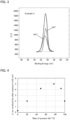
- the background processing was performed by Shirley method, and curve fitting by a nonlinear least square method was used for the peak resolution. As a typical result, the result of Example 2 is shown in FIG 3 .
- Ge3d spectrum obtained by the XPS measurement was separated into the peak of Ge 4+ and the peak of Ge 2+ , and the present rate of Ge 2+ was obtained from each of the peak area. The results are shown in Table 1.
- a Li-ion conductivity measurement was respectively conducted to the sulfide solid state electrolytes obtained in Examples 1 to 5 and Comparative Example 1.
- the sulfide solid electrolyte was weighted to be 100 mg, in a glove box with a dew point of -80°C, put in a cylinder made of macole, and pressed by the pressure of 4 ton/cm 2 . Both edges of the obtained pellet were pinched by a pin made of SUS, restraining pressure was applied to the pellet by bolting, and thereby an evaluation cell was obtained.
- the Li ion conductivity at 25°C of the evaluation cell was calculated by A.C. impedance method.
- Solartron 1260 was used with applied voltage: 5 mV and measurement frequency range: 0.01 MHz to 1 MHz.
- the results (Li ion conductivity before the exposure test) are shown in Table 1.
- Example 1 0 8.0 0.3 3.8 Vacuum Example 1 20 7.3 2.0 27.4 N 2 + O 2 Example 2 49 7.5 4.2 56.0 N 2 Example 3 77 5.2 5.0 96.2 Ar ⁇ N 2 Example 4 92 4.3 4.2 97.7 Ar Example 5 100 2.1 2.0 95.2 Ar + H 2
- the present rate of Ge 2+ was 0%. In other words, all Ge present in the particle surface of the sulfide solid electrolyte was Ge 4+ . In contrast, the present rate of Ge 2+ in Examples 1 to 5 was respectively 20% or more. Also, as shown in Table 1 and FIG. 4 , the Li ion conductivity after the exposure test of Examples 1 to 5 was respectively higher than that of Comparative Example 1. Among them, the Li ion conductivity after the exposure test was high in Examples 2 to 4, and in particular, that of Example 3 was the highest. In other words, it was suggested that the maximum value exists between Example 2 and Example 4.
- Example 2 was higher than that of Example 1, and the durability of Examples 3 to 5 was respectively remarkably higher than that of Example 2. Also, when Examples 3 and 4 are compared to Example 5, the Li ion conductivity after the exposure test of Examples 3 and 4 was respectively higher than that of Example 5, and the durability of the Li ion conductivity before and after the exposure test was equivalent in Examples 3 to 5. Also, from the results of Examples 1 to 5 and Comparative Example 1, it is clear that the present rate of Ge 2+ gives an effect to the water resistance of the sulfide solid electrolyte. For this reason, from the viewpoint of water resistance over time, it was suggested that Example 5 was superior.
- Example 2 when Example 2 is compared to Example 4, it was confirmed that the reduction power of reducing Ge 4+ to Ge 2+ of nitrogen gas was weaker than that of argon gas.
- the nitrogen gas and the argon gas has been generally known as gas with low reactivity, but there was surprisingly large difference in the present rate of Ge 2+ between when the nitrogen gas was used and when the argon gas was used. The reason for the large difference is not completely clear, but there is a possibility that the reactivity of the nitrogen was lower than that of the argon gas, since the nitrogen gas itself is categorized as a neutralization gas. Also, since sulfur included in the precursor is presumably volatilized during firing, some kind of interaction occurs among the sulfur volatilized, the nitrogen gas and the argon gas, and there is also a possibility that the large difference occurred due to the strength and weakness of that interaction.
- Example 2 when Example 2 is compared to Example 1, it was confirmed that the reduction power of reducing Ge 4+ to Ge 2+ was restrained when the oxygen gas that was an oxidative gas was added to the nitrogen gas. Similarly, when Example 4 is compared to Example 5, it was confirmed that the reduction power of reducing Ge 4+ to Ge 2+ was enhanced when the hydrogen gas that was a reductive gas was added to the argon gas. In this manner, it was confirmed that the present rate of Ge 2+ was controlled when the oxidative gas and the reductive gas were used. Also, although an experiment was not conducted in particular, when an oxidative gas is added to the argon gas, it is expected that the present rate of Ge 2+ would be in the same level as that of Example 3. Similarly, when a reductive gas is added to the nitrogen gas, it is expected that the present rate of Ge 2+ would be in the same level as that of Example 3.
- Example 3 the first firing treatment in which the argon gas was flowed, and the second firing treatment in which the nitrogen gas was flowed were performed.
- the present rate of Ge 2+ is presumably 92% similarly to that of Example 4, but after the performance of the second firing treatment, the present rate of Ge 2+ was reduced to 77%.
- the reason therefor is not clear, but it is presumed that there was a possibility the amount of Ge 4+ dispersed from inside the particles was more than the amount of Ge 4+ reduced to Ge 2+ by the nitrogen gas.
Landscapes
- Chemical & Material Sciences (AREA)
- Engineering & Computer Science (AREA)
- Chemical Kinetics & Catalysis (AREA)
- General Chemical & Material Sciences (AREA)
- Organic Chemistry (AREA)
- Electrochemistry (AREA)
- Materials Engineering (AREA)
- Manufacturing & Machinery (AREA)
- Inorganic Chemistry (AREA)
- Geochemistry & Mineralogy (AREA)
- Life Sciences & Earth Sciences (AREA)
- Ceramic Engineering (AREA)
- Physics & Mathematics (AREA)
- Condensed Matter Physics & Semiconductors (AREA)
- General Physics & Mathematics (AREA)
- Dispersion Chemistry (AREA)
- Crystallography & Structural Chemistry (AREA)
- Structural Engineering (AREA)
- Secondary Cells (AREA)
- Conductive Materials (AREA)
- Battery Electrode And Active Subsutance (AREA)
Abstract
Description
- The present disclosure relates to a sulfide solid electrolyte.
- An all solid state battery is a battery including a solid electrolyte layer between a cathode active material layer and an anode active material layer, and one of the advantages thereof is that the simplification of a safety device may be more easily achieved compared to a liquid-based battery including a liquid electrolyte containing a flammable organic solvent. As a solid electrolyte used for an all solid state battery, sulfide solid electrolytes have been known. Among sulfide solid electrolytes, a LGPS-based sulfide solid electrolyte has been known as a material with high Li ion conductivity.
- For example,
Patent Literature 1 discloses a method for producing a LGPS-based solid electrolyte, the method comprising a step of synthesizing a precursor by mixing a Li3PS4 crystal and a Li4MS4 crystal (M = Ge, Si, Sn) with the presence of the crystals, and a step of heat treating the precursor at 300 to 700°C. Also,Patent Literatures 2 to 4 respectively disclose a LGPS-based sulfide solid electrolyte. -
- Patent Literature 1: International Application Publication:
WO 2018/173939 - Patent Literature 2: Japanese Patent Application Laid-Open (
JP-A) No. 2017-021965 - Patent Literature 3:
JP-A No. 2019-501105 - Patent Literature 4: International Application Publication:
WO 2019/044517 - The LGPS-based sulfide solid electrolyte is a material with high Li ion conductivity; however, the Li ion conductivity will be degraded by water included in an atmosphere. For this reason, improvement in its water resistance has been desired. The present disclosure has been made in view of the above circumstances, and a main object thereof is to provide a sulfide solid electrolyte with excellent water resistance.
- The present disclosure provides a sulfide solid electrolyte including a LGPS type crystal phase, and containing Li, Ge, P, and S, wherein: when an X-ray photoelectron spectroscopy measurement is conducted to a surface of the sulfide solid electrolyte, a proportion of Ge2+ with respect to total amount of Ge is 20% or more.
- According to the present disclosure, the proportion of Ge2+ in the specified rate with respect to the total amount of Ge allows the sulfide solid electrolyte to have excellent water resistance.
- In the disclosure, the proportion of the Ge2+ may be 92% or less.
- In the disclosure, the proportion of the Ge2+ may be 49% or more.
- In the disclosure, the proportion of the Ge2+ may be 55% or more and 90% or less.
- In the disclosure, the proportion of the Ge2+ may be 94% or more.
- In the disclosure, the proportion of the Ge2+ may be 100%.
- The present disclosure also provides an all solid state battery comprising a cathode active material layer, an anode active material layer, and a solid electrolyte layer arranged between the cathode active material layer and the anode active material layer, wherein at least one of the cathode active material layer, the anode active material layer, and the solid electrolyte layer contains the above described sulfide solid electrolyte.
- According to the present disclosure, usage of the above described sulfide solid electrolyte allows the all solid state battery to maintain its output properties even under environment such as in high humidity.
- The present disclosure also provides a method for producing the above described sulfide solid electrolyte, the method comprising: a preparing step of preparing a precursor containing Li, Ge, P, and S; and a firing step of firing the precursor under an atmosphere with gas containing at least one of a nitrogen gas and a noble gas to form the LGPS type crystal phase.
- According to the present disclosure, the firing is performed in the specified gas atmosphere, and thus a sulfide solid electrolyte with excellent water resistance may be obtained.
- In the disclosure, the gas may contain the nitrogen gas.
- In the disclosure, the gas may contain an argon gas as the noble gas.
- In the disclosure, the gas may contain an oxidative gas.
- In the disclosure, the gas may contain a reductive gas.
- In the disclosure, the firing step may comprise: a first firing treatment of firing the precursor under an atmosphere with a first gas containing an argon gas; and a second firing treatment of firing the precursor after the first firing treatment under an atmosphere with a second gas containing a nitrogen gas.
- In the disclosure, the precursor may be a sulfide glass.
- The present disclosure exhibits an effect of providing a sulfide solid electrolyte with excellent water resistance.
-
-
FIG. 1 is a schematic cross-sectional view exemplifying the all solid state battery in the present disclosure. -
FIG. 2 is a flow chart exemplifying the method for producing the sulfide solid electrolyte in the present disclosure. -
FIG. 3 is the result of an XPS measurement to the sulfide solid electrolyte produced in Example 2. -
FIG. 4 is a graph showing the relation between the present rate of Ge2+ and the Li ion conductivity after the exposure test. - The sulfide solid electrolyte, the all solid state battery, and the method for producing the sulfide solid electrolyte in the present disclosure will be hereinafter explained in details.
- The sulfide solid electrolyte in the present disclosure includes a LGPS type crystal phase, and contains Li, Ge, P, and S, wherein: when an X-ray photoelectron spectroscopy measurement is conducted to a surface of the sulfide solid electrolyte, a proportion of Ge2+ with respect to total amount of Ge is 20% or more.
- According to the present disclosure, the proportion of Ge2+ in the specified rate with respect to the total amount of Ge allows the sulfide solid electrolyte to have excellent water resistance. The sulfide solid electrolyte including the LGPS type crystal phase is a material with high Li ion conductivity; however, the Li ion conductivity will be degraded by water included in an atmosphere. For this reason, improvement in its water resistance has been desired. In the present disclosure, the proportion of Ge2+ with respect to the total amount of Ge is the specified rate, and thus the sulfide solid electrolyte may have excellent water resistance. Here, as described in Examples later, when a sulfide glass is fired in a vacuum, the Ge present in the surface of the particle will all be Ge4+. In other words, the proportion of Ge2+ (present rate of Ge2+) with respect to the total amount of Ge will be 0%. In contrast, in the present disclosure, the proportion of Ge2+ can be controlled by, for example, adjusting the kinds of gas to be used for firing. In specific, the gas used for firing will form a reductive layer (Ge2+ layer) with high water resistance on the surface of the particle. By adjusting the kind of the gas, the rate of the reductive layer (Ge2+ layer) can be controlled. In the present disclosure, the proportion of the Ge2+ is set to the specified rate or more, and thus a sulfide solid electrolyte with excellent water resistance may be obtained. The reason why excellent water resistance is obtained thereby is presumably because the Ge2+ has more excellent water resistance than that of the Ge4+. This point is also suggested from the fact that the solubility of GeS to water is lower than that of GeS2.
- The sulfide solid electrolyte in the present disclosure contains Li, Ge, P and S. The total proportion of Li, Ge, P and S with respect to all the elements included in the sulfide solid electrolyte is, for example, 70 mol% or more, may be 80 mol% or more, and may be 90 mol% or more. Also, the sulfide solid electrolyte may or may not contain halogen. In the former case, the sulfide solid electrolyte may contain just one kind of the halogen, and may contain two kinds or more of the halogen. Examples of the halogen may include Cl, Br, and I.
- The sulfide solid electrolyte in the present disclosure includes a LGPS-type crystal phase. In the present disclosure, the LGPS-type crystal phase refers to a crystal phase including Li, Ge, P and S. The LGPS-type crystal phase has typical peaks at the positions of 2θ = 20.18°± 0.50°, 20.44°± 0.50°, 26.96°± 0.50°, and 29.58°± 0.50°in an X-ray diffraction measurement using a Cu-Kα ray. Also, the LGPS-type crystal phase may include peaks at the positions of 2θ = 17.38°± 0.50°, 23.56°± 0.50°, 23.96°± 0.50°, 24.93°± 0.50°, 29.07°± 0.50°, 31.71°± 0.50°, 32.66°± 0.50°, and 33.39°± 0.50°. Incidentally, these peak positions may shift depending on factors such as the composition of the sulfide solid electrolyte, and thus the positions are specified in the range of ± 0.50°. The range of the positions of each peak may be ± 0.30°, and may be ± 0.10°.
- Also, the LGPS-type crystal phase is usually a crystal phase including an octahedron O (such as LiS6 octahedron) configured by a Li element and a S element, a tetrahedron T1 (such as GeS4 and PS4) configured by a M2a element (M2a is at least one kind of P and Ge) and a S element, and a tetrahedron T2 (such as PS4) configured by a M2b element (M2b is at least one kind of P and Ge) and a S element, wherein the tetrahedron T1 and the octahedron O share edges, and the tetrahedron T2 and the octahedron O share the top.
- The sulfide solid electrolyte in the present disclosure preferably includes the LGPS-type crystal phase as a main phase. "Including as a main phase" means that the proportion of the LGPS-type crystal phase is the largest with respect to all the crystal phases included in the sulfide solid electrolyte. The proportion of the LGPS-type crystal phase is, for example, 50 weight% or more, may be 70 weight% or more and may be 90 weight% or more. Incidentally, the proportion of the crystal phase can be measured by, for example, a radiation XRD.
- Also, in the present disclosure, when an X-ray photoelectron spectroscopy measurement is conducted to a surface of the sulfide solid electrolyte, a proportion of Ge2+ with respect to total amount of Ge is 20% or more. The proportion of Ge2+ with respect to total amount of Ge may be 49% or more, may be 50% or more, may be 55% or more, and may be 60% or more. If the proportion of Ge2+ with respect to total amount of Ge is too little, there is a possibility that the Li ion conductivity after the exposure to water may be degraded. Also, the proportion of Ge2+ with respect to total amount of Ge may be 92% or less, may be 90% or less, and may be 85% or less. When the proportion of Ge2+ is in the above described range, the Li ion conductivity after the exposure to water may be high. As described in Examples later, when the proportion of Ge2+ with respect to total amount of Ge is 49% or more and 92% or less (preferably when 55% or more and 90% or less), the Li ion conductivity after the exposure to water may particularly be high. The method for calculating the proportion of Ge2+ with respect to total amount of Ge will be described in Examples later.
- Also, in the present disclosure, when an X-ray photoelectron spectroscopy measurement is conducted to a surface of the sulfide solid electrolyte, a proportion of Ge2+ with respect to total amount of Ge may be 77% or more, may be 92% or more, may be 94% or more, may be 96% or more, and may be 100%. When the proportion of Ge2+ is increased, the durability of the Li ion conductivity after the exposure to water may be high.
- Also, in the present disclosure, when an X-ray photoelectron spectroscopy measurement is conducted to a surface of the sulfide solid electrolyte, a proportion of Ge2+ with respect to total amount of Ge may be 45% or less. When the proportion of Ge2+ is in the above described range, the Li ion conductivity after the exposure to water may be high.
- There are no particular limitations on the composition of the sulfide solid electrolyte in the present disclosure. The sulfide solid electrolyte may have a composition represented by, for example, αLiX·(1-α)(Li4-xGe1-xPxS4) provided that X is one kind or two kinds or more of halogen, α satisfies 0 ≤ α < 1, and x satisfies 0 < x < 1. Examples of the X may include Cl, Br, and I. The α may be 0 and may be larger than 0. In the latter case, the α may be 0.1 or more and may be 0.2 or more. Meanwhile, the α may be 0.5 or less, and may be 0.4 or less. The x may be 0.5 or more, and may be 0.6 or more. Meanwhile, the x may be 0.8 or less, and may be 0.75 or less.
- The sulfide solid electrolyte in the present disclosure preferably has high Li ion conductivity. The Li ion conductivity of the sulfide solid electrolyte at 25°C is, for example, 1 * 10-4 S/cm or more, and may be 1 * 10-3 S/cm or more. Also, the sulfide solid electrolyte preferably has high Li ion conductivity after the specified exposure test. The Li ion conductivity at 25°C after the exposure test is, for example, 1 * 10-4 S/cm or more, and may be 1 * 10-3 S/cm or more.
- The exposure test is, as described in Examples later, a test in which the sulfide solid electrolyte is placed still for 6 hours in a glove box with the dew point controlled to -30°C so that the sulfide solid electrolyte is exposed to water included in the atmosphere. When IC1 designates the Li ion conductivity before the exposure test, and IC2 designates the Li ion conductivity after the exposure test, IC2/IC1 (durability of the Li ion conductivity before and after the exposure test) is, for example, 27% or more, may be 56% or more, and may be 95% or more.
- Examples of the shape of the sulfide solid electrolyte may include a granular shape. The average particle size (D50) of the sulfide solid electrolyte is, for example, 0.1 µm or more, may be 0.5 µm or more, and may be 1 µm or more. Meanwhile, the average particle size (D50) of the sulfide solid electrolyte is, for example, 50 µm or less, and may be 30 µm or less. The average particle size (D50) may be obtained from, for example, the result of a particle distribution measurement by a laser diffraction scattering method.
- The sulfide solid electrolyte in the present disclosure has excellent Li ion conductivity, and thus can be used in arbitrary applications that require the Li ion conductivity. Above all, the sulfide solid electrolyte is preferably used for an all solid state battery. Also, the method for producing the sulfide solid electrolyte in the present disclosure is not particularly limited, but examples thereof may include "C. Method for producing sulfide solid electrolyte" described later.
-
FIG. 1 is a schematic cross-sectional view exemplifying the all solid state battery in the present disclosure. Allsolid state battery 10 illustrated inFIG. 1 comprises cathodeactive material layer 1 containing a cathode active material, anodeactive material layer 2 containing an anode active material,solid electrolyte layer 3 arranged between the cathodeactive material layer 1 and the anodeactive material layer 2, cathodecurrent collector 4 for collecting currents of cathodeactive material layer 1, anodecurrent collector 5 for collecting currents of anodeactive material layer 2, andbattery case 6 for storing these members. The present disclosure features that at least one of the cathodeactive material layer 1, the anodeactive material layer 2, and thesolid electrolyte layer 3 contains the above described sulfide solid electrolyte. - According to the present disclosure, usage of the above described sulfide solid electrolyte allows the all solid state battery to maintain its output properties even under environment such as in high humidity.
- The cathode active material layer is a layer containing at least a cathode active material, and may contain at least one of a solid electrolyte, a conductive material and a binder, as required. In particular, in the present disclosure, it is preferable that the cathode active material layer contains the above described sulfide solid electrolyte. The proportion of the sulfide solid electrolyte included in the cathode active material layer is, for example, 0.1 volume% or more, may be 1 volume% or more, and may be 10 volume% or more. Meanwhile, the proportion of the sulfide solid electrolyte included in the cathode active material layer is, for example, 80 volume% or less, may be 60 volume% or less, and may be 50 volume% or less. Also, examples of the cathode active material may include an oxide active material such as LiCoO2, LiMnO2, LiNiO2, LiNi1/3Co1/3Mn1/3O2, LiVO2, LiCrO2, Li2NiMn3O8, LiFePO4, and LiCoPO4.
- The cathode active material layer may contain a conductive material. Addition of the conductive material improves the electron conductivity of the cathode active material layer. Examples of the conductive material may include a carbon material such as acetylene black, Ketjen black, and carbon fiber. Also, the cathode active material layer may contain a binder. Examples of the binder may include a fluorine-based binder such as polyvinylidene fluoride (PVDF). Also, the thickness of the cathode active material layer is, for example, 0.1 µm or more and 1000 µm or less.
- The anode active material layer is a layer containing at least an anode active material, and may contain at least one of a solid electrolyte, a conductive material and a binder, as required. In particular, in the present disclosure, it is preferable that the anode active material layer contains the above described sulfide solid electrolyte. The proportion of the sulfide solid electrolyte included in the anode active material layer is, for example, 0.1 volume% or more, may be 1 volume% or more, and may be 10 volume% or more. Meanwhile, the proportion of the sulfide solid electrolyte included in the anode active material layer is, for example, 80 volume% or less, may be 60 volume% or less, and may be 50 volume% or less. Also, examples of the anode active material may include a metal active material and a carbon active material. Examples of the metal active material may include In, Al, Si, and Sn. Meanwhile, examples of the carbon active material may include methocarbon microbeads (MCMB), highly oriented pyrolytic graphite (HOPG), hard carbon, and soft carbon.
- Incidentally, the conductive material and the binder to be used in the anode active material layer are the same as those used in the above described cathode active material layer. Also, the thickness of the anode active material layer is, for example, 0.1 µm or more and 1000 µm or less.
- The solid electrolyte layer is a layer arranged between the cathode active material layer and the anode active material layer. Also, the solid electrolyte layer is a layer that contains at least a solid electrolyte, and may contain a binder as required. In particular, in the present disclosure, the solid electrolyte layer preferably contains the above described sulfide solid electrolyte. The proportion of the sulfide solid electrolyte included in the solid electrolyte layer is, for example, 50 volume% or more, may be 70 volume% or more, and may be 90 volume% or more. Incidentally, the binder to be used in the solid electrolyte layer is the same as that used in the above described cathode active material layer. Also, the thickness of the solid electrolyte layer is, for example, 0.1 µm or more and 1000 µm or less.
- The all solid state battery in the present disclosure comprises at least the above described cathode active material layer, solid electrolyte layer and anode active material layer. Further, the battery usually comprises a cathode current collector for collecting currents of the cathode active material layer and an anode current collector for collecting currents of the anode active material layer. Examples of the material for the cathode current collector may include SUS, aluminum, nickel, iron, titanium and carbon. Meanwhile, examples of the material for the anode current collector may include SUS, copper, nickel, and carbon.
- The all solid state battery in the present disclosure is usually an all solid lithium ion battery. Also, the all solid state battery may be a primary battery and may be a secondary battery, but the latter is preferable. The reason therefor is to be repeatedly charged and discharged and useful as a car-mounted battery for example.
-
FIG. 2 is a flow-chart exemplifying the method for producing the sulfide solid electrolyte in the present disclosure. InFIG. 2 , first, a precursor containing Li, Ge, P, and S is prepared (a preparing step). Next, the prepared precursor is fired under an atmosphere with gas containing at least one of a nitrogen gas and a noble gas to form the LGPS type crystal phase (a firing step). Thereby, the above described sulfide solid electrolyte is obtained. - According to the present disclosure, the firing is performed in the specified gas atmosphere, and thus a sulfide solid electrolyte with excellent water resistance may be obtained.
- The preparing step in the present disclosure is a step of preparing a precursor containing Li, Ge, P, and S. The precursor may be a raw material mixture, may be a sulfide glass, and may include the LGPS-type crystal phase.
- First, the case where the precursor is a raw material mixture will be explained. The precursor usually contains a Li source, a Ge source, a P source, and a S source. Examples of the Li source may include a simple substance of Li and a lithium sulfide (such as Li2S). Examples of the Ge source may include a simple substance of Ge and a germanium sulfide (such as GeS2). Examples of the P source may include a simple substance of P and a phosphorus sulfide (such as P2S5). Examples of the S source may include a simple substance of S, a germanium sulfide and a phosphorus sulfide. Also, the raw material mixture may or may not contain LiX (X is a halogen).
- There are no particular limitations on the composition of the raw material mixture. The raw material mixture may include a composition represented by, for example, αLiX · (1-α) (Li4-xGe1-xPxS4) provided that X is one kind or two kinds or more of halogen, α satisfies 0 ≤ α < 1, and x satisfies 0 < x < 1. The X, the α and the x are in the same contents as those described in "A. Sulfide solid electrolyte" above. Also, the raw material mixture may be obtained by mixing each raw material by a mixing device (such as an agate mortar).
- Next, the case where the precursor is a sulfide glass will be explained. The sulfide glass may be obtained by, for example, conducting mechanical milling to the raw material mixture. Examples of the mechanical milling may include ball milling, vibration milling, turbo milling, and disc milling. Also, the sulfide lass may be obtained by, for example, melting and quenching the raw material mixture. The sulfide glass usually includes amorphous properties. In other words, a halo pattern is observed in the sulfide glass in an X-ray diffraction measurement. In addition, the sulfide glass may or may not include a peak derived from the raw materials, but the latter is preferable. The reason therefore is to obtain higher amorphous properties.
- Next, the case where the precursor includes the LGPS-type crystal phase will be explained. Such a precursor may be obtained by, for example, conducting a heat treatment to the raw material mixture or the sulfide glass. The heat treatment temperature is, for example, 300°C or more, may be 400°C or more, and may be 500°C or more. Also, the heat treatment temperature is, for example, 1000°C or less and may be 700°C or less. Examples of the heat treatment atmosphere may include a reduced pressure atmosphere such as vacuum. The heat treatment time is, for example, 1 hour or more and 20 hours or less.
- The firing step in the present disclosure is a step of firing the precursor under an atmosphere with gas containing at least one of a nitrogen gas and a noble gas to form the LGPS type crystal phase. In the present disclosure, the specified gas is used to reduce Ge4+ in the surface of the particle to Ge2+, and thereby a sulfide solid electrolyte with high proportion of Ge2+ is obtained. Also, the proportion of Ge2+ with respect to total amount of Ge may be adjusted by adjusting the composition of the gas used during the firing.
- The gas (atmosphere gas) used during the firing contains at least one of a nitrogen gas and a noble gas. Examples of the noble gas may include an argon gas and a helium gas. The nitrogen gas has lower reduction power of reducing Ge4+ to Ge2+, compared to the noble gas. Incidentally, in the present disclosure, the nitrogen gas and the noble gas are referred to as a standard gas. The proportion of the standard gas in the atmosphere gas is, for example, 90 volume% or more, may be 95 volume% or more, and may be 99 volume% or more.
- Also, the atmosphere gas may contain an oxidative gas. Addition of the oxidative gas may restrain the reduction power of the standard gas. Examples of the oxidative gas may include an oxygen gas, an oxygen-containing gas such as dry air, and a carbon dioxide gas. Also, the proportion of the oxidative gas in the atmosphere gas is, for example, 0.01 volume% or more and 1 volume% or less.
- Also, the atmosphere gas may contain a reductive gas. Addition of the reductive gas may enhance the reduction power of the standard gas. Examples of the reductive gas may include a hydrocarbon gas such as a hydrogen gas, a carbon monoxide gas, methane, propane, and butane. Also, the proportion of the reductive gas in the atmosphere gas is, for example, 0.01 volume% or more and 1 volume% or less.
- Also, in the present disclosure, it is preferable to flow the gas during the firing. The reason therefor is to facilitate the reduction of Ge4+ in the particle surface to Ge2+. The firing temperature is, for example, 300°C or more, may be 400°C or more, and may be 500°C or more. Also, the firing temperature is, for example, 1000°C or less, and may be 700°C or less. The firing time is, for example, 1 hour or more and 20 hours or less.
- Also, in the present disclosure, the firing step may include: a first firing treatment of firing the precursor under an atmosphere with a first gas containing an argon gas; and a second firing treatment of firing the precursor after the first firing treatment under an atmosphere with a second gas containing a nitrogen gas. By performing the first firing treatment and the second firing treatment, a sulfide solid electrolyte with high Li ion conductivity after the exposure test and also with high durability before and after the exposure test may be obtained. The first firing treatment and the second firing treatment may be performed continuously, and cooling may be performed after the first firing treatment and then the second firing treatment may be performed thereafter. In the latter case, cooling may be performed until the room temperature after the first firing treatment. Also, the firing temperature and the firing time in the first firing treatment and the second firing treatment are respectively in the same contents as those described above.
- The sulfide solid electrolyte obtained by each step described above is in the same contents as those described in "A. Sulfide solid electrolyte" above; thus, the descriptions herein are omitted.
- The present disclosure is not limited to the embodiments. The embodiments are exemplification, and any other variations are intended to be included in the technical scope of the present disclosure if they have substantially the same constitution as the technical idea described in the claims of the present disclosure and have similar operation and effect thereto.
- As raw materials, Li2S, P2S5 and GeS2 were prepared, and these were weighed to have the composition of Li10GeP2S12, and the product was put in a zirconium pot together with zirconium balls. After that, mechanical milling (mechanical alloying) was conducted thereto in the conditions of 380 rpm and 40 hours by a planetary ball mill, and thereby a sulfide glass was obtained. The obtained sulfide glass was formed into pellet, vacuum-sealed in a quartz tube, fired in the conditions of 550°C and 8 hours, and thereby a sulfide solid electrolyte was obtained.
- A sulfide glass was obtained in the same manner as in Comparative Example 1. The obtained sulfide glass was placed on an alumina board, and with a tube furnace, firing was performed thereto in the conditions of 550°C and 8 hours while flowing a gas in which 0.2 volume% of an oxygen gas was added to a nitrogen gas, and thereby a sulfide solid electrolyte was obtained.
- A sulfide glass was obtained in the same manner as in Comparative Example 1. The obtained sulfide glass was placed on an alumina board, and with a tube furnace, firing was performed thereto in the conditions of 550°C and 8 hours while flowing a nitrogen gas, and thereby a sulfide solid electrolyte was obtained.
- A sulfide glass was obtained in the same manner as in Comparative Example 1. The obtained sulfide glass was placed on an alumina board, and with a tube furnace, firing was performed thereto in the conditions of 550°C and 8 hours while flowing an argon gas. The product was cooled until the room temperature, and then again, with a tube furnace, firing was performed thereto in the conditions of 550°C and 8 hours while flowing a nitrogen gas, and thereby a sulfide solid electrolyte was obtained.
- A sulfide glass was obtained in the same manner as in Comparative Example 1. The obtained sulfide glass was placed on an alumina board, and with a tube furnace, firing was performed thereto in the conditions of 550°C and 8 hours while flowing an argon gas, and thereby a sulfide solid electrolyte was obtained.
- A sulfide glass was obtained in the same manner as in Comparative Example 1. The obtained sulfide glass was placed on an alumina board, and with a tube furnace, firing was performed thereto in the conditions of 550°C and 8 hours while flowing a gas in which 0.2 volume% of a hydrogen gas was added to an argon gas, and thereby a sulfide solid electrolyte was obtained.
- An X-ray diffraction (XRD) measurement was respectively conducted to the sulfide solid electrolytes obtained in Examples 1 to 5 and Comparative Example 1. As a result, it was confirmed that all the sulfide solid electrolytes obtained in Examples 1 to 5 and Comparative Example 1 had the LGPS-type crystal phase.
- An X-ray photoelectron spectroscopy (XPS) measurement was respectively conducted to the sulfide solid electrolytes obtained in Examples 1 to 5 and Comparative Example 1, and thereby the structures of the sulfide solid electrolytes were evaluated. As the measurement device for the X-ray photoelectron spectroscopy, an XPS device PHI-5800 from ULVAC-PHI, INCORPORATED was used. A sample was put in a holder for the XPS measurement in a glove box with an argon atmosphere, the holder was vacuumed for 30 minutes or more in a preliminary exhaust room, and then introduced to a chemical laboratory. In the measurement, an X-ray source of monochromatic AlKα (1487 eV) was used, and the information of the outermost surface of the sample was obtained. The measurement area was approximately 100 µmφ, and a neutralization gun of Ar+ electron beam was used for neutralizing charges.
- Peak resolution of Ge3d spectrum obtained by the XPS measurement was conducted, and the peak area A of Ge4+ corresponding to high energy, and the peak area B of Ge2+ corresponding to low energy were calculated. With the calculated peak areas, the present rate of Ge2+ (B/(A+B)) was obtained, and signified as "the proportion of Ge2+ with respect to total amount of Ge". The peak resolution was conducted by an analyzing software (MULTI PACK from ULVAC-PHI, INCORPORATED) attached to the measurement device of the X-ray photoelectron spectroscopy. The background processing was performed by Shirley method, and curve fitting by a nonlinear least square method was used for the peak resolution. As a typical result, the result of Example 2 is shown in
FIG 3 . In specific, as shown inFIG. 3 , Ge3d spectrum obtained by the XPS measurement was separated into the peak of Ge4+ and the peak of Ge2+, and the present rate of Ge2+ was obtained from each of the peak area. The results are shown in Table 1. - A Li-ion conductivity measurement was respectively conducted to the sulfide solid state electrolytes obtained in Examples 1 to 5 and Comparative Example 1. In specific, the sulfide solid electrolyte was weighted to be 100 mg, in a glove box with a dew point of -80°C, put in a cylinder made of macole, and pressed by the pressure of 4 ton/cm2. Both edges of the obtained pellet were pinched by a pin made of SUS, restraining pressure was applied to the pellet by bolting, and thereby an evaluation cell was obtained. The Li ion conductivity at 25°C of the evaluation cell was calculated by A.C. impedance method. In the measurement, Solartron 1260 was used with applied voltage: 5 mV and measurement frequency range: 0.01 MHz to 1 MHz. The results (Li ion conductivity before the exposure test) are shown in Table 1.
- An exposure test was respectively conducted to the sulfide solid state electrolytes obtained in Examples 1 to 5 and Comparative Example 1. In specific, the sulfide solid electrolyte was placed still for 6 hours in a glove box of which dew point is controlled to -30°C, and thereby the sulfide solid electrolyte was exposed to water included in the atmosphere. The Li ion conductivity after the exposure test was calculated in the same manner as above. The results are shown in Table 1 and
FIG. 4 .[Table 1] Ge2+ Present rate (%) Li ion conductivity Firing atmosphere Before exposure (mS/cm) After exposure (mS/cm) Durability (%) Comp. Ex. 1 0 8.0 0.3 3.8 Vacuum Example 1 20 7.3 2.0 27.4 N2 + O2 Example 2 49 7.5 4.2 56.0 N2 Example 3 77 5.2 5.0 96.2 Ar → N2 Example 4 92 4.3 4.2 97.7 Ar Example 5 100 2.1 2.0 95.2 Ar + H2 - As shown in Table 1, when firing was performed in vacuum as in Comparative Example 1, the present rate of Ge2+ was 0%. In other words, all Ge present in the particle surface of the sulfide solid electrolyte was Ge4+. In contrast, the present rate of Ge2+ in Examples 1 to 5 was respectively 20% or more. Also, as shown in Table 1 and
FIG. 4 , the Li ion conductivity after the exposure test of Examples 1 to 5 was respectively higher than that of Comparative Example 1. Among them, the Li ion conductivity after the exposure test was high in Examples 2 to 4, and in particular, that of Example 3 was the highest. In other words, it was suggested that the maximum value exists between Example 2 and Example 4. - Also, from the viewpoint of the durability of the Li ion conductivity before and after the exposure test, the durability of Example 2 was higher than that of Example 1, and the durability of Examples 3 to 5 was respectively remarkably higher than that of Example 2. Also, when Examples 3 and 4 are compared to Example 5, the Li ion conductivity after the exposure test of Examples 3 and 4 was respectively higher than that of Example 5, and the durability of the Li ion conductivity before and after the exposure test was equivalent in Examples 3 to 5. Also, from the results of Examples 1 to 5 and Comparative Example 1, it is clear that the present rate of Ge2+ gives an effect to the water resistance of the sulfide solid electrolyte. For this reason, from the viewpoint of water resistance over time, it was suggested that Example 5 was superior.
- Also, the results of Examples 1 to 5 will be considered in details. First, when Example 2 is compared to Example 4, it was confirmed that the reduction power of reducing Ge4+ to Ge2+ of nitrogen gas was weaker than that of argon gas. The nitrogen gas and the argon gas has been generally known as gas with low reactivity, but there was surprisingly large difference in the present rate of Ge2+ between when the nitrogen gas was used and when the argon gas was used. The reason for the large difference is not completely clear, but there is a possibility that the reactivity of the nitrogen was lower than that of the argon gas, since the nitrogen gas itself is categorized as a neutralization gas. Also, since sulfur included in the precursor is presumably volatilized during firing, some kind of interaction occurs among the sulfur volatilized, the nitrogen gas and the argon gas, and there is also a possibility that the large difference occurred due to the strength and weakness of that interaction.
- Next, when Example 2 is compared to Example 1, it was confirmed that the reduction power of reducing Ge4+ to Ge2+ was restrained when the oxygen gas that was an oxidative gas was added to the nitrogen gas. Similarly, when Example 4 is compared to Example 5, it was confirmed that the reduction power of reducing Ge4+ to Ge2+ was enhanced when the hydrogen gas that was a reductive gas was added to the argon gas. In this manner, it was confirmed that the present rate of Ge2+ was controlled when the oxidative gas and the reductive gas were used. Also, although an experiment was not conducted in particular, when an oxidative gas is added to the argon gas, it is expected that the present rate of Ge2+ would be in the same level as that of Example 3. Similarly, when a reductive gas is added to the nitrogen gas, it is expected that the present rate of Ge2+ would be in the same level as that of Example 3.
- Next, in Example 3, the first firing treatment in which the argon gas was flowed, and the second firing treatment in which the nitrogen gas was flowed were performed. In the stage when the first firing treatment was completed, the present rate of Ge2+ is presumably 92% similarly to that of Example 4, but after the performance of the second firing treatment, the present rate of Ge2+ was reduced to 77%. The reason therefor is not clear, but it is presumed that there was a possibility the amount of Ge4+ dispersed from inside the particles was more than the amount of Ge4+ reduced to Ge2+ by the nitrogen gas.
-
- 1
- cathode active material layer
- 2
- anode active material layer
- 3
- solid electrolyte layer
- 4
- cathode current collector
- 5
- anode current collector
- 6
- battery case
- 10
- all solid state battery
Claims (14)
- A sulfide solid electrolyte characterized by comprising a LGPS type crystal phase, and containing Li, Ge, P, and S, wherein:
when an X-ray photoelectron spectroscopy measurement is conducted to a surface of the sulfide solid electrolyte, a proportion of Ge2+ with respect to total amount of Ge is 20% or more. - The sulfide solid electrolyte according to claim 1, characterized in that the proportion of the Ge2+ is 92% or less.
- The sulfide solid electrolyte according to claim 1 or 2, characterized in that the proportion of the Ge2+ is 49% or more.
- The sulfide solid electrolyte according to claim 1, characterized in that the proportion of the Ge2+ is 55% or more and 90% or less.
- The sulfide solid electrolyte according to claim 1, characterized in that the proportion of the Ge2+ is 94% or more.
- The sulfide solid electrolyte according to claim 1, characterized in that the proportion of the Ge2+ is 100%.
- An all solid state battery comprising a cathode active material layer, an anode active material layer, and a solid electrolyte layer arranged between the cathode active material layer and the anode active material layer, characterized in that:
at least one of the cathode active material layer, the anode active material layer, and the solid electrolyte layer contains the sulfide solid electrolyte according to any one of claims 1 to 6. - A method for producing the sulfide solid electrolyte according to any one of claims 1 to 6, the method characterized by comprising:a preparing step of preparing a precursor containing Li, Ge, P, and S; anda firing step of firing the precursor under an atmosphere with gas containing at least one of a nitrogen gas and a noble gas to form the LGPS type crystal phase.
- The method for producing the sulfide solid electrolyte according to claim 8, characterized in that the gas contains the nitrogen gas.
- The method for producing the sulfide solid electrolyte according to claim 8 or 9, characterize in that the gas contains an argon gas as the noble gas.
- The method for producing the sulfide solid electrolyte according to any one of claims 8 to 10, characterized in that the gas contains an oxidative gas.
- The method for producing the sulfide solid electrolyte according to any one of claims 8 to 10, characterized in that the gas contains a reductive gas.
- The method for producing the sulfide solid electrolyte according to claim 8, characterized in that the firing step comprises:a first firing treatment of firing the precursor under an atmosphere with a first gas containing an argon gas; anda second firing treatment of firing the precursor after the first firing treatment under an atmosphere with a second gas containing a nitrogen gas.
- The method for producing the sulfide solid electrolyte according to any one of claims 8 to 13, characterized in that the precursor is a sulfide glass.
Applications Claiming Priority (1)
| Application Number | Priority Date | Filing Date | Title |
|---|---|---|---|
| JP2021165304A JP7578571B2 (en) | 2021-10-07 | 2021-10-07 | Sulfide solid electrolyte, all-solid-state battery, and method for producing sulfide solid electrolyte |
Publications (2)
| Publication Number | Publication Date |
|---|---|
| EP4164006A1 true EP4164006A1 (en) | 2023-04-12 |
| EP4164006B1 EP4164006B1 (en) | 2024-11-27 |
Family
ID=83598387
Family Applications (1)
| Application Number | Title | Priority Date | Filing Date |
|---|---|---|---|
| EP22199832.1A Active EP4164006B1 (en) | 2021-10-07 | 2022-10-05 | Sulfide solid electrolyte, all solid state battery, and method for producing sulfide solid electrolyte |
Country Status (5)
| Country | Link |
|---|---|
| US (1) | US12500265B2 (en) |
| EP (1) | EP4164006B1 (en) |
| JP (1) | JP7578571B2 (en) |
| KR (1) | KR102812446B1 (en) |
| CN (1) | CN115954533B (en) |
Citations (6)
| Publication number | Priority date | Publication date | Assignee | Title |
|---|---|---|---|---|
| JP2017021965A (en) | 2015-07-09 | 2017-01-26 | 国立大学法人東京工業大学 | Lithium solid electrolyte |
| KR20170056338A (en) * | 2015-11-13 | 2017-05-23 | 한국전기연구원 | Normal pressure synthesis of sulfide solid electrolyte composition for the solid lithium secondary batteries |
| WO2018173939A1 (en) | 2017-03-22 | 2018-09-27 | 三菱瓦斯化学株式会社 | Production method for lgps-based solid electrolyte |
| JP2019501105A (en) | 2015-12-22 | 2019-01-17 | トヨタ・モーター・ヨーロッパToyota Motor Europe | Solid electrolyte materials |
| WO2019044517A1 (en) | 2017-09-01 | 2019-03-07 | 三菱瓦斯化学株式会社 | Method for producing lgps-based solid electrolyte |
| JP2021118038A (en) * | 2020-01-22 | 2021-08-10 | 三菱瓦斯化学株式会社 | Method for producing sulfide-based solid electrolyte |
Family Cites Families (7)
| Publication number | Priority date | Publication date | Assignee | Title |
|---|---|---|---|---|
| GB1020482A (en) * | 1961-11-07 | 1966-02-16 | Pilkington Brothers Ltd | Improvements in or relating to glass |
| EP2988361B1 (en) * | 2010-03-26 | 2017-05-10 | Tokyo Institute Of Technology | Sulfide solid electrolyte material, battery, and method for producing sulfide solid electrolyte material |
| WO2014171483A1 (en) * | 2013-04-16 | 2014-10-23 | トヨタ自動車株式会社 | Sulfide solid electrolyte material, cell, and method for manufacturing sulfide solid electrolyte material |
| US20190121433A1 (en) | 2017-10-20 | 2019-04-25 | Immersion Corporation | Determining a haptic profile using a built-in accelerometer |
| CN108428936A (en) * | 2018-03-13 | 2018-08-21 | 西安电子科技大学 | A kind of doping O2-Lithium ion solid electrolyte material of ion and preparation method thereof |
| JP7119753B2 (en) * | 2018-08-16 | 2022-08-17 | 三菱瓦斯化学株式会社 | Method for producing LGPS-based solid electrolyte |
| CN113363569B (en) * | 2021-06-30 | 2023-05-05 | 国联汽车动力电池研究院有限责任公司 | High-stability inorganic sulfide solid electrolyte and preparation method thereof |
-
2021
- 2021-10-07 JP JP2021165304A patent/JP7578571B2/en active Active
-
2022
- 2022-09-30 KR KR1020220125649A patent/KR102812446B1/en active Active
- 2022-10-03 US US17/958,785 patent/US12500265B2/en active Active
- 2022-10-05 EP EP22199832.1A patent/EP4164006B1/en active Active
- 2022-10-08 CN CN202211222614.5A patent/CN115954533B/en active Active
Patent Citations (6)
| Publication number | Priority date | Publication date | Assignee | Title |
|---|---|---|---|---|
| JP2017021965A (en) | 2015-07-09 | 2017-01-26 | 国立大学法人東京工業大学 | Lithium solid electrolyte |
| KR20170056338A (en) * | 2015-11-13 | 2017-05-23 | 한국전기연구원 | Normal pressure synthesis of sulfide solid electrolyte composition for the solid lithium secondary batteries |
| JP2019501105A (en) | 2015-12-22 | 2019-01-17 | トヨタ・モーター・ヨーロッパToyota Motor Europe | Solid electrolyte materials |
| WO2018173939A1 (en) | 2017-03-22 | 2018-09-27 | 三菱瓦斯化学株式会社 | Production method for lgps-based solid electrolyte |
| WO2019044517A1 (en) | 2017-09-01 | 2019-03-07 | 三菱瓦斯化学株式会社 | Method for producing lgps-based solid electrolyte |
| JP2021118038A (en) * | 2020-01-22 | 2021-08-10 | 三菱瓦斯化学株式会社 | Method for producing sulfide-based solid electrolyte |
Also Published As
| Publication number | Publication date |
|---|---|
| CN115954533B (en) | 2026-03-13 |
| JP2023056149A (en) | 2023-04-19 |
| EP4164006B1 (en) | 2024-11-27 |
| KR102812446B1 (en) | 2025-05-23 |
| CN115954533A (en) | 2023-04-11 |
| KR20230050242A (en) | 2023-04-14 |
| US12500265B2 (en) | 2025-12-16 |
| JP7578571B2 (en) | 2024-11-06 |
| US20230253613A1 (en) | 2023-08-10 |
Similar Documents
| Publication | Publication Date | Title |
|---|---|---|
| EP2425483B1 (en) | Solid electrolyte material, electrode element that includes solid electrolyte material, all-solid battery that includes solid electrolyte material, and manufacturing method for solid electrolyte material | |
| EP2592683B1 (en) | Solid electrolyte material and lithium battery | |
| EP2609652B1 (en) | Sulfide solid electrolyte material, cathode body and lithium solid state battery | |
| EP2555307B1 (en) | Sulfide solid electrolyte material, battery, and method for producing sulfide solid electrolyte material | |
| US12374716B2 (en) | Sulfide solid electrolyte and all solid state battery | |
| EP3007262B1 (en) | Sulfide solid electrolyte material, cell, and method for producing sulfide solid electrolyte material | |
| US12500261B2 (en) | Lithium ion conducting solid materials | |
| EP3930068B1 (en) | Sulfide solid electrolyte and method for the preparation thereof, all solid-state lithium secondary battery, and apparatus containing the same | |
| EP4001213A1 (en) | Oxide, method of preparing the same, solid electrolyte including the oxide, and electrochemical device including the oxide | |
| Dou et al. | Enhancing the electrochemical performance of LiNi0. 8Co0. 1Mn0. 1O2 cathodes through amorphous coatings | |
| Hu et al. | Reversibility of metal-hydride anodes in all-solid-state lithium secondary battery operating at room temperature | |
| Tian et al. | LiMnO2@ rGO nanocomposites for high‐performance lithium‐ion battery cathodes | |
| Zhao et al. | Enhanced electrochemical performance of LiNi0. 8Co0. 15Al0. 05O2 cathode by reducing lithium residue with low-temperature fluorination treatment | |
| US11063289B2 (en) | Increasing ionic conductivity of lithium titanium thiophosphate by sintering | |
| US20230387454A1 (en) | Solid lithium ion conducting material containing ytterbium and process for preparation thereof | |
| EP4614609A1 (en) | Positive electrode active material for lithium ion secondary batteries, and lithium ion secondary battery | |
| EP4614608A1 (en) | Positive electrode active material for lithium ion secondary battery, and lithium ion secondary battery | |
| EP4164006B1 (en) | Sulfide solid electrolyte, all solid state battery, and method for producing sulfide solid electrolyte | |
| EP4441807B1 (en) | Coated particulate material for use in an electrode of an electrochemical cell | |
| Hou et al. | Inert Gas‐Based Protective Layer Engineering for Stabilizing Nickel‐Rich Cathodes at High Voltages | |
| Feng et al. | Systematic theoretical investigation of Li5NbWO8 as a novel solid electrolyte via first-principles calculations | |
| EP4489032A1 (en) | Lithium ion conductive solid electrolyte | |
| JP2002373657A (en) | Method for producing negative electrode for non-aqueous electrolyte secondary battery and non-aqueous electrolyte secondary battery | |
| US20260142225A1 (en) | Solid-state battery with enhanced solid electrolyte | |
| Park et al. | Comparative study of the stability of composite cathodes based on sulfide solid electrolytes for all-solid-state lithium-ion batteries |
Legal Events
| Date | Code | Title | Description |
|---|---|---|---|
| PUAI | Public reference made under article 153(3) epc to a published international application that has entered the european phase |
Free format text: ORIGINAL CODE: 0009012 |
|
| STAA | Information on the status of an ep patent application or granted ep patent |
Free format text: STATUS: REQUEST FOR EXAMINATION WAS MADE |
|
| 17P | Request for examination filed |
Effective date: 20221021 |
|
| AK | Designated contracting states |
Kind code of ref document: A1 Designated state(s): AL AT BE BG CH CY CZ DE DK EE ES FI FR GB GR HR HU IE IS IT LI LT LU LV MC ME MK MT NL NO PL PT RO RS SE SI SK SM TR |
|
| STAA | Information on the status of an ep patent application or granted ep patent |
Free format text: STATUS: EXAMINATION IS IN PROGRESS |
|
| 17Q | First examination report despatched |
Effective date: 20230928 |
|
| REG | Reference to a national code |
Ref country code: DE Ref legal event code: R079 Free format text: PREVIOUS MAIN CLASS: H01M0004660000 Ipc: C01B0017220000 Ref country code: DE Ref legal event code: R079 Ref document number: 602022008141 Country of ref document: DE Free format text: PREVIOUS MAIN CLASS: H01M0004660000 Ipc: C01B0017220000 |
|
| GRAP | Despatch of communication of intention to grant a patent |
Free format text: ORIGINAL CODE: EPIDOSNIGR1 |
|
| STAA | Information on the status of an ep patent application or granted ep patent |
Free format text: STATUS: GRANT OF PATENT IS INTENDED |
|
| RIC1 | Information provided on ipc code assigned before grant |
Ipc: H01M 6/18 20060101ALN20240620BHEP Ipc: C04B 35/547 20060101ALI20240620BHEP Ipc: H01M 10/0562 20100101ALI20240620BHEP Ipc: H01M 10/052 20100101ALI20240620BHEP Ipc: H01M 4/66 20060101ALI20240620BHEP Ipc: C03C 10/00 20060101ALI20240620BHEP Ipc: C03C 3/32 20060101ALI20240620BHEP Ipc: C01B 17/22 20060101AFI20240620BHEP |
|
| INTG | Intention to grant announced |
Effective date: 20240702 |
|
| GRAS | Grant fee paid |
Free format text: ORIGINAL CODE: EPIDOSNIGR3 |
|
| GRAA | (expected) grant |
Free format text: ORIGINAL CODE: 0009210 |
|
| STAA | Information on the status of an ep patent application or granted ep patent |
Free format text: STATUS: THE PATENT HAS BEEN GRANTED |
|
| AK | Designated contracting states |
Kind code of ref document: B1 Designated state(s): AL AT BE BG CH CY CZ DE DK EE ES FI FR GB GR HR HU IE IS IT LI LT LU LV MC ME MK MT NL NO PL PT RO RS SE SI SK SM TR |
|
| REG | Reference to a national code |
Ref country code: GB Ref legal event code: FG4D |
|
| REG | Reference to a national code |
Ref country code: CH Ref legal event code: EP |
|
| REG | Reference to a national code |
Ref country code: IE Ref legal event code: FG4D |
|
| REG | Reference to a national code |
Ref country code: DE Ref legal event code: R096 Ref document number: 602022008141 Country of ref document: DE |
|
| REG | Reference to a national code |
Ref country code: LT Ref legal event code: MG9D |
|
| REG | Reference to a national code |
Ref country code: NL Ref legal event code: MP Effective date: 20241127 |
|
| PG25 | Lapsed in a contracting state [announced via postgrant information from national office to epo] |
Ref country code: PT Free format text: LAPSE BECAUSE OF FAILURE TO SUBMIT A TRANSLATION OF THE DESCRIPTION OR TO PAY THE FEE WITHIN THE PRESCRIBED TIME-LIMIT Effective date: 20250327 Ref country code: HR Free format text: LAPSE BECAUSE OF FAILURE TO SUBMIT A TRANSLATION OF THE DESCRIPTION OR TO PAY THE FEE WITHIN THE PRESCRIBED TIME-LIMIT Effective date: 20241127 Ref country code: IS Free format text: LAPSE BECAUSE OF FAILURE TO SUBMIT A TRANSLATION OF THE DESCRIPTION OR TO PAY THE FEE WITHIN THE PRESCRIBED TIME-LIMIT Effective date: 20250327 |
|
| PG25 | Lapsed in a contracting state [announced via postgrant information from national office to epo] |
Ref country code: FI Free format text: LAPSE BECAUSE OF FAILURE TO SUBMIT A TRANSLATION OF THE DESCRIPTION OR TO PAY THE FEE WITHIN THE PRESCRIBED TIME-LIMIT Effective date: 20241127 Ref country code: NL Free format text: LAPSE BECAUSE OF FAILURE TO SUBMIT A TRANSLATION OF THE DESCRIPTION OR TO PAY THE FEE WITHIN THE PRESCRIBED TIME-LIMIT Effective date: 20241127 |
|
| REG | Reference to a national code |
Ref country code: AT Ref legal event code: MK05 Ref document number: 1745565 Country of ref document: AT Kind code of ref document: T Effective date: 20241127 |
|
| PG25 | Lapsed in a contracting state [announced via postgrant information from national office to epo] |
Ref country code: BG Free format text: LAPSE BECAUSE OF FAILURE TO SUBMIT A TRANSLATION OF THE DESCRIPTION OR TO PAY THE FEE WITHIN THE PRESCRIBED TIME-LIMIT Effective date: 20241127 |
|
| PG25 | Lapsed in a contracting state [announced via postgrant information from national office to epo] |
Ref country code: ES Free format text: LAPSE BECAUSE OF FAILURE TO SUBMIT A TRANSLATION OF THE DESCRIPTION OR TO PAY THE FEE WITHIN THE PRESCRIBED TIME-LIMIT Effective date: 20241127 |
|
| PG25 | Lapsed in a contracting state [announced via postgrant information from national office to epo] |
Ref country code: NO Free format text: LAPSE BECAUSE OF FAILURE TO SUBMIT A TRANSLATION OF THE DESCRIPTION OR TO PAY THE FEE WITHIN THE PRESCRIBED TIME-LIMIT Effective date: 20250227 |
|
| PG25 | Lapsed in a contracting state [announced via postgrant information from national office to epo] |
Ref country code: GR Free format text: LAPSE BECAUSE OF FAILURE TO SUBMIT A TRANSLATION OF THE DESCRIPTION OR TO PAY THE FEE WITHIN THE PRESCRIBED TIME-LIMIT Effective date: 20250228 Ref country code: LV Free format text: LAPSE BECAUSE OF FAILURE TO SUBMIT A TRANSLATION OF THE DESCRIPTION OR TO PAY THE FEE WITHIN THE PRESCRIBED TIME-LIMIT Effective date: 20241127 Ref country code: AT Free format text: LAPSE BECAUSE OF FAILURE TO SUBMIT A TRANSLATION OF THE DESCRIPTION OR TO PAY THE FEE WITHIN THE PRESCRIBED TIME-LIMIT Effective date: 20241127 |
|
| PG25 | Lapsed in a contracting state [announced via postgrant information from national office to epo] |
Ref country code: PL Free format text: LAPSE BECAUSE OF FAILURE TO SUBMIT A TRANSLATION OF THE DESCRIPTION OR TO PAY THE FEE WITHIN THE PRESCRIBED TIME-LIMIT Effective date: 20241127 |
|
| PG25 | Lapsed in a contracting state [announced via postgrant information from national office to epo] |
Ref country code: RS Free format text: LAPSE BECAUSE OF FAILURE TO SUBMIT A TRANSLATION OF THE DESCRIPTION OR TO PAY THE FEE WITHIN THE PRESCRIBED TIME-LIMIT Effective date: 20250227 |
|
| PG25 | Lapsed in a contracting state [announced via postgrant information from national office to epo] |
Ref country code: SM Free format text: LAPSE BECAUSE OF FAILURE TO SUBMIT A TRANSLATION OF THE DESCRIPTION OR TO PAY THE FEE WITHIN THE PRESCRIBED TIME-LIMIT Effective date: 20241127 |
|
| PG25 | Lapsed in a contracting state [announced via postgrant information from national office to epo] |
Ref country code: DK Free format text: LAPSE BECAUSE OF FAILURE TO SUBMIT A TRANSLATION OF THE DESCRIPTION OR TO PAY THE FEE WITHIN THE PRESCRIBED TIME-LIMIT Effective date: 20241127 |
|
| PG25 | Lapsed in a contracting state [announced via postgrant information from national office to epo] |
Ref country code: EE Free format text: LAPSE BECAUSE OF FAILURE TO SUBMIT A TRANSLATION OF THE DESCRIPTION OR TO PAY THE FEE WITHIN THE PRESCRIBED TIME-LIMIT Effective date: 20241127 |
|
| PG25 | Lapsed in a contracting state [announced via postgrant information from national office to epo] |
Ref country code: RO Free format text: LAPSE BECAUSE OF FAILURE TO SUBMIT A TRANSLATION OF THE DESCRIPTION OR TO PAY THE FEE WITHIN THE PRESCRIBED TIME-LIMIT Effective date: 20241127 |
|
| PG25 | Lapsed in a contracting state [announced via postgrant information from national office to epo] |
Ref country code: SK Free format text: LAPSE BECAUSE OF FAILURE TO SUBMIT A TRANSLATION OF THE DESCRIPTION OR TO PAY THE FEE WITHIN THE PRESCRIBED TIME-LIMIT Effective date: 20241127 |
|
| PG25 | Lapsed in a contracting state [announced via postgrant information from national office to epo] |
Ref country code: CZ Free format text: LAPSE BECAUSE OF FAILURE TO SUBMIT A TRANSLATION OF THE DESCRIPTION OR TO PAY THE FEE WITHIN THE PRESCRIBED TIME-LIMIT Effective date: 20241127 |
|
| PG25 | Lapsed in a contracting state [announced via postgrant information from national office to epo] |
Ref country code: IT Free format text: LAPSE BECAUSE OF FAILURE TO SUBMIT A TRANSLATION OF THE DESCRIPTION OR TO PAY THE FEE WITHIN THE PRESCRIBED TIME-LIMIT Effective date: 20241127 |
|
| REG | Reference to a national code |
Ref country code: DE Ref legal event code: R097 Ref document number: 602022008141 Country of ref document: DE |
|
| PG25 | Lapsed in a contracting state [announced via postgrant information from national office to epo] |
Ref country code: SE Free format text: LAPSE BECAUSE OF FAILURE TO SUBMIT A TRANSLATION OF THE DESCRIPTION OR TO PAY THE FEE WITHIN THE PRESCRIBED TIME-LIMIT Effective date: 20241127 |
|
| PLBE | No opposition filed within time limit |
Free format text: ORIGINAL CODE: 0009261 |
|
| STAA | Information on the status of an ep patent application or granted ep patent |
Free format text: STATUS: NO OPPOSITION FILED WITHIN TIME LIMIT |
|
| REG | Reference to a national code |
Ref country code: CH Ref legal event code: L10 Free format text: ST27 STATUS EVENT CODE: U-0-0-L10-L00 (AS PROVIDED BY THE NATIONAL OFFICE) Effective date: 20251008 |
|
| 26N | No opposition filed |
Effective date: 20250828 |
|
| PGFP | Annual fee paid to national office [announced via postgrant information from national office to epo] |
Ref country code: DE Payment date: 20250902 Year of fee payment: 4 |
|
| REG | Reference to a national code |
Ref country code: DE Ref legal event code: R081 Ref document number: 602022008141 Country of ref document: DE Owner name: INSTITUTE OF SCIENCE TOKYO, JP Free format text: FORMER OWNERS: TOKYO INSTITUTE OF TECHNOLOGY, TOKYO, JP; TOYOTA JIDOSHA KABUSHIKI KAISHA, TOYOTA-SHI, AICHI-KEN, JP Ref country code: DE Ref legal event code: R081 Ref document number: 602022008141 Country of ref document: DE Owner name: TOYOTA JIDOSHA KABUSHIKI KAISHA, TOYOTA-SHI, JP Free format text: FORMER OWNERS: TOKYO INSTITUTE OF TECHNOLOGY, TOKYO, JP; TOYOTA JIDOSHA KABUSHIKI KAISHA, TOYOTA-SHI, AICHI-KEN, JP |
|
| REG | Reference to a national code |
Ref country code: DE Ref legal event code: R084 Ref document number: 602022008141 Country of ref document: DE |
|
| REG | Reference to a national code |
Ref country code: CH Ref legal event code: H13 Free format text: ST27 STATUS EVENT CODE: U-0-0-H10-H13 (AS PROVIDED BY THE NATIONAL OFFICE) Effective date: 20260527 |
|
| PG25 | Lapsed in a contracting state [announced via postgrant information from national office to epo] |
Ref country code: LU Free format text: LAPSE BECAUSE OF NON-PAYMENT OF DUE FEES Effective date: 20251005 |
|
| REG | Reference to a national code |
Ref country code: BE Ref legal event code: MM Effective date: 20251031 |
|
| PG25 | Lapsed in a contracting state [announced via postgrant information from national office to epo] |
Ref country code: LT Free format text: LAPSE BECAUSE OF FAILURE TO SUBMIT A TRANSLATION OF THE DESCRIPTION OR TO PAY THE FEE WITHIN THE PRESCRIBED TIME-LIMIT Effective date: 20241127 |
|
| PG25 | Lapsed in a contracting state [announced via postgrant information from national office to epo] |
Ref country code: MC Free format text: LAPSE BECAUSE OF FAILURE TO SUBMIT A TRANSLATION OF THE DESCRIPTION OR TO PAY THE FEE WITHIN THE PRESCRIBED TIME-LIMIT Effective date: 20241127 |
|
| PG25 | Lapsed in a contracting state [announced via postgrant information from national office to epo] |
Ref country code: CH Free format text: LAPSE BECAUSE OF NON-PAYMENT OF DUE FEES Effective date: 20251031 Ref country code: BE Free format text: LAPSE BECAUSE OF NON-PAYMENT OF DUE FEES Effective date: 20251031 |
|
| PG25 | Lapsed in a contracting state [announced via postgrant information from national office to epo] |
Ref country code: FR Free format text: LAPSE BECAUSE OF NON-PAYMENT OF DUE FEES Effective date: 20251031 |