EP4163718A1 - Vibration body and vibration wave motor - Google Patents
Vibration body and vibration wave motor Download PDFInfo
- Publication number
- EP4163718A1 EP4163718A1 EP21818296.2A EP21818296A EP4163718A1 EP 4163718 A1 EP4163718 A1 EP 4163718A1 EP 21818296 A EP21818296 A EP 21818296A EP 4163718 A1 EP4163718 A1 EP 4163718A1
- Authority
- EP
- European Patent Office
- Prior art keywords
- vibrator
- vibration wave
- wave motor
- electromechanical transducer
- temperature
- Prior art date
- Legal status (The legal status is an assumption and is not a legal conclusion. Google has not performed a legal analysis and makes no representation as to the accuracy of the status listed.)
- Granted
Links
Images









Classifications
-
- G—PHYSICS
- G02—OPTICS
- G02B—OPTICAL ELEMENTS, SYSTEMS OR APPARATUS
- G02B7/00—Mountings, adjusting means, or light-tight connections, for optical elements
- G02B7/02—Mountings, adjusting means, or light-tight connections, for optical elements for lenses
- G02B7/04—Mountings, adjusting means, or light-tight connections, for optical elements for lenses with mechanism for focusing or varying magnification
- G02B7/08—Mountings, adjusting means, or light-tight connections, for optical elements for lenses with mechanism for focusing or varying magnification adapted to co-operate with a remote control mechanism
-
- C—CHEMISTRY; METALLURGY
- C04—CEMENTS; CONCRETE; ARTIFICIAL STONE; CERAMICS; REFRACTORIES
- C04B—LIME, MAGNESIA; SLAG; CEMENTS; COMPOSITIONS THEREOF, e.g. MORTARS, CONCRETE OR LIKE BUILDING MATERIALS; ARTIFICIAL STONE; CERAMICS; REFRACTORIES; TREATMENT OF NATURAL STONE
- C04B35/00—Shaped ceramic products characterised by their composition; Ceramics compositions; Processing powders of inorganic compounds preparatory to the manufacturing of ceramic products
- C04B35/01—Shaped ceramic products characterised by their composition; Ceramics compositions; Processing powders of inorganic compounds preparatory to the manufacturing of ceramic products based on oxide ceramics
- C04B35/495—Shaped ceramic products characterised by their composition; Ceramics compositions; Processing powders of inorganic compounds preparatory to the manufacturing of ceramic products based on oxide ceramics based on vanadium, niobium, tantalum, molybdenum or tungsten oxides or solid solutions thereof with other oxides, e.g. vanadates, niobates, tantalates, molybdates or tungstates
-
- G—PHYSICS
- G02—OPTICS
- G02B—OPTICAL ELEMENTS, SYSTEMS OR APPARATUS
- G02B7/00—Mountings, adjusting means, or light-tight connections, for optical elements
- G02B7/008—Mountings, adjusting means, or light-tight connections, for optical elements with means for compensating for changes in temperature or for controlling the temperature; thermal stabilisation
-
- G—PHYSICS
- G02—OPTICS
- G02B—OPTICAL ELEMENTS, SYSTEMS OR APPARATUS
- G02B7/00—Mountings, adjusting means, or light-tight connections, for optical elements
- G02B7/02—Mountings, adjusting means, or light-tight connections, for optical elements for lenses
- G02B7/021—Mountings, adjusting means, or light-tight connections, for optical elements for lenses for more than one lens
-
- G—PHYSICS
- G02—OPTICS
- G02B—OPTICAL ELEMENTS, SYSTEMS OR APPARATUS
- G02B7/00—Mountings, adjusting means, or light-tight connections, for optical elements
- G02B7/02—Mountings, adjusting means, or light-tight connections, for optical elements for lenses
- G02B7/023—Mountings, adjusting means, or light-tight connections, for optical elements for lenses permitting adjustment
-
- H—ELECTRICITY
- H02—GENERATION; CONVERSION OR DISTRIBUTION OF ELECTRIC POWER
- H02N—ELECTRIC MACHINES NOT OTHERWISE PROVIDED FOR
- H02N2/00—Electric machines in general using piezoelectric effect, electrostriction or magnetostriction
- H02N2/0005—Electric machines in general using piezoelectric effect, electrostriction or magnetostriction producing non-specific motion; Details common to machines covered by H02N2/02 - H02N2/16
- H02N2/001—Driving devices, e.g. vibrators
- H02N2/003—Driving devices, e.g. vibrators using longitudinal or radial modes combined with bending modes
- H02N2/004—Rectangular vibrators
-
- H—ELECTRICITY
- H02—GENERATION; CONVERSION OR DISTRIBUTION OF ELECTRIC POWER
- H02N—ELECTRIC MACHINES NOT OTHERWISE PROVIDED FOR
- H02N2/00—Electric machines in general using piezoelectric effect, electrostriction or magnetostriction
- H02N2/02—Electric machines in general using piezoelectric effect, electrostriction or magnetostriction producing linear motion, e.g. actuators; Linear positioners ; Linear motors
- H02N2/026—Electric machines in general using piezoelectric effect, electrostriction or magnetostriction producing linear motion, e.g. actuators; Linear positioners ; Linear motors by pressing one or more vibrators against the driven body
-
- H—ELECTRICITY
- H02—GENERATION; CONVERSION OR DISTRIBUTION OF ELECTRIC POWER
- H02N—ELECTRIC MACHINES NOT OTHERWISE PROVIDED FOR
- H02N2/00—Electric machines in general using piezoelectric effect, electrostriction or magnetostriction
- H02N2/10—Electric machines in general using piezoelectric effect, electrostriction or magnetostriction producing rotary motion, e.g. rotary motors
- H02N2/16—Electric machines in general using piezoelectric effect, electrostriction or magnetostriction producing rotary motion, e.g. rotary motors using travelling waves, i.e. Rayleigh surface waves
- H02N2/163—Motors with ring stator
-
- H—ELECTRICITY
- H10—SEMICONDUCTOR DEVICES; ELECTRIC SOLID-STATE DEVICES NOT OTHERWISE PROVIDED FOR
- H10N—ELECTRIC SOLID-STATE DEVICES NOT OTHERWISE PROVIDED FOR
- H10N30/00—Piezoelectric or electrostrictive devices
- H10N30/80—Constructional details
- H10N30/85—Piezoelectric or electrostrictive active materials
- H10N30/853—Ceramic compositions
- H10N30/8542—Alkali metal based oxides, e.g. lithium, sodium or potassium niobates
-
- C—CHEMISTRY; METALLURGY
- C04—CEMENTS; CONCRETE; ARTIFICIAL STONE; CERAMICS; REFRACTORIES
- C04B—LIME, MAGNESIA; SLAG; CEMENTS; COMPOSITIONS THEREOF, e.g. MORTARS, CONCRETE OR LIKE BUILDING MATERIALS; ARTIFICIAL STONE; CERAMICS; REFRACTORIES; TREATMENT OF NATURAL STONE
- C04B2235/00—Aspects relating to ceramic starting mixtures or sintered ceramic products
- C04B2235/02—Composition of constituents of the starting material or of secondary phases of the final product
- C04B2235/30—Constituents and secondary phases not being of a fibrous nature
- C04B2235/32—Metal oxides, mixed metal oxides, or oxide-forming salts thereof, e.g. carbonates, nitrates, (oxy)hydroxides, chlorides
- C04B2235/3231—Refractory metal oxides, their mixed metal oxides, or oxide-forming salts thereof
- C04B2235/3232—Titanium oxides or titanates, e.g. rutile or anatase
- C04B2235/3234—Titanates, not containing zirconia
- C04B2235/3236—Alkaline earth titanates
-
- C—CHEMISTRY; METALLURGY
- C04—CEMENTS; CONCRETE; ARTIFICIAL STONE; CERAMICS; REFRACTORIES
- C04B—LIME, MAGNESIA; SLAG; CEMENTS; COMPOSITIONS THEREOF, e.g. MORTARS, CONCRETE OR LIKE BUILDING MATERIALS; ARTIFICIAL STONE; CERAMICS; REFRACTORIES; TREATMENT OF NATURAL STONE
- C04B2235/00—Aspects relating to ceramic starting mixtures or sintered ceramic products
- C04B2235/02—Composition of constituents of the starting material or of secondary phases of the final product
- C04B2235/30—Constituents and secondary phases not being of a fibrous nature
- C04B2235/32—Metal oxides, mixed metal oxides, or oxide-forming salts thereof, e.g. carbonates, nitrates, (oxy)hydroxides, chlorides
- C04B2235/3231—Refractory metal oxides, their mixed metal oxides, or oxide-forming salts thereof
- C04B2235/3251—Niobium oxides, niobates, tantalum oxides, tantalates, or oxide-forming salts thereof
- C04B2235/3255—Niobates or tantalates, e.g. silver niobate
-
- C—CHEMISTRY; METALLURGY
- C04—CEMENTS; CONCRETE; ARTIFICIAL STONE; CERAMICS; REFRACTORIES
- C04B—LIME, MAGNESIA; SLAG; CEMENTS; COMPOSITIONS THEREOF, e.g. MORTARS, CONCRETE OR LIKE BUILDING MATERIALS; ARTIFICIAL STONE; CERAMICS; REFRACTORIES; TREATMENT OF NATURAL STONE
- C04B2235/00—Aspects relating to ceramic starting mixtures or sintered ceramic products
- C04B2235/02—Composition of constituents of the starting material or of secondary phases of the final product
- C04B2235/30—Constituents and secondary phases not being of a fibrous nature
- C04B2235/32—Metal oxides, mixed metal oxides, or oxide-forming salts thereof, e.g. carbonates, nitrates, (oxy)hydroxides, chlorides
- C04B2235/327—Iron group oxides, their mixed metal oxides, or oxide-forming salts thereof
-
- G—PHYSICS
- G03—PHOTOGRAPHY; CINEMATOGRAPHY; ANALOGOUS TECHNIQUES USING WAVES OTHER THAN OPTICAL WAVES; ELECTROGRAPHY; HOLOGRAPHY
- G03B—APPARATUS OR ARRANGEMENTS FOR TAKING PHOTOGRAPHS OR FOR PROJECTING OR VIEWING THEM; APPARATUS OR ARRANGEMENTS EMPLOYING ANALOGOUS TECHNIQUES USING WAVES OTHER THAN OPTICAL WAVES; ACCESSORIES THEREFOR
- G03B2205/00—Adjustment of optical system relative to image or object surface other than for focusing
- G03B2205/0053—Driving means for the movement of one or more optical element
- G03B2205/0061—Driving means for the movement of one or more optical element using piezoelectric actuators
-
- G—PHYSICS
- G03—PHOTOGRAPHY; CINEMATOGRAPHY; ANALOGOUS TECHNIQUES USING WAVES OTHER THAN OPTICAL WAVES; ELECTROGRAPHY; HOLOGRAPHY
- G03B—APPARATUS OR ARRANGEMENTS FOR TAKING PHOTOGRAPHS OR FOR PROJECTING OR VIEWING THEM; APPARATUS OR ARRANGEMENTS EMPLOYING ANALOGOUS TECHNIQUES USING WAVES OTHER THAN OPTICAL WAVES; ACCESSORIES THEREFOR
- G03B3/00—Focusing arrangements of general interest for cameras, projectors or printers
- G03B3/10—Power-operated focusing
Definitions
- the disclosure relates to a vibrator and a vibration wave motor.
- a vibration wave motor produces a traveling vibration wave (abbreviated as a traveling wave below) on a driving surface of an elastic body by using expansion and contraction of a piezoelectric body, this traveling wave causes an elliptical motion on the driving surface, and a mover placed in pressure contact with a crest of the elliptical motion is driven.
- JP 01-017354 B2 does not take into account a decrease in driving performance caused by a material of the piezoelectric body.
- a vibrator of a first disclosure comprises an electromechanical transducer which is a piezoelectric ceramic made of sodium-potassium niobate metal oxides and whose temperature characteristics of a relative permittivity is 500 [ppm/°C] or less in absolute value in a temperature range from -40°C to 170°C, wherein excitation of the electromechanical transducer produces a vibration wave.
- an electromechanical transducer which is a piezoelectric ceramic made of sodium-potassium niobate metal oxides and whose temperature characteristics of a relative permittivity is 500 [ppm/°C] or less in absolute value in a temperature range from -40°C to 170°C, wherein excitation of the electromechanical transducer produces a vibration wave.
- a vibrator of a second disclosure comprises an electromechanical transducer which is a piezoelectric ceramic made of sodium-potassium niobate metal oxides and whose temperature characteristics of a relative permittivity is 390 [ppm/°C] or less in absolute value in a temperature range from 0°C to 60°C, wherein excitation of the electromechanical transducer produces a vibration wave.
- an electromechanical transducer which is a piezoelectric ceramic made of sodium-potassium niobate metal oxides and whose temperature characteristics of a relative permittivity is 390 [ppm/°C] or less in absolute value in a temperature range from 0°C to 60°C, wherein excitation of the electromechanical transducer produces a vibration wave.
- a vibration wave motor of a third disclosure comprises: the vibrator according to any one of the first and second disclosure; and a relative motion member which includes a sliding surface placed in pressure contact with a driving surface of the vibrator, and is caused to make a relative motion by the vibration wave.
- a vibration wave motor produces a traveling wave on a driving surface of an elastic body by using expansion and contraction of a piezoelectric body, this traveling wave causes an elliptical motion on the driving surface, and a mover placed in pressure contact with a crest of the elliptical motion is driven.
- the vibration wave motor includes that the vibration wave motor has a high torque even in a case of low rotation, and in a case where the vibration wave motor is mounted on a driving device, a gear of the driving device can be omitted. Consequently, by canceling gear noise, it is possible to achieve noise reduction, and improve positioning accuracy.
- a vibrator of this vibration wave motor generally includes an electromechanical transducer (abbreviated as a piezoelectric body below) and an elastic body.
- the piezoelectric body is generally formed by a material such as lead zirconate titanate which is commonly called PZT.
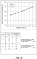
- Fig. 18 is a graph illustrating an example of temperature characteristics of an electrostatic capacitance of PZT (made by Fuji Ceramics Corporation) which is a material of the piezoelectric body prepared for the vibration wave motor. It is found that the electrostatic capacitance has an inclination of approximately 4.4 [pF/°C] ( ⁇ 2750 [ppm/°C]) with respect to a temperature.
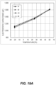
- Fig. 19A is a graph illustrating an example of temperature characteristics of an electrostatic capacitance of the vibrator of the vibration wave motor in a case where the PZT in Fig. 18 is a piezoelectric body material (part 1).
- Fig. 19B is a graph illustrating an example of temperature characteristics of an electrostatic capacitance of the vibrator of the vibration wave motor in a case where the PZT in Fig. 18 is a piezoelectric body material (part 2). It is found that the electrostatic capacitances have an inclination of approximately 6.2 [pF/°C] ( ⁇ 4430 [ppm/°C]) with respect to a temperature. This inclination indicates that, for example, when the temperature becomes lower, the electrostatic capacitance of the piezoelectric body decreases more, and, when the temperature becomes higher, the electrostatic capacitance of the piezoelectric body increases more.
- Fig. 20 is a graph obtained by measuring a current input at each temperature for the vibration wave motor of a PZT-mounted product.
- a drive voltage was set to 70 [Vrms]
- a current input to the vibration wave motor at a time when the vibration wave motor was driven at a predetermined rotation speed was measured.
- a phenomenon is that, while an input current decreases more when the temperature becomes lower, the input current increases more when the temperature becomes higher compared to a current at a normal temperature. This phenomenon matches with temperature characteristics of an electrostatic capacitance value of the vibrator illustrated in Figs. 19A and 19B .
- the electrostatic capacitance of the vibrator decreases more when the temperature becomes lower, an impedance increases, and therefore the input current decreases
- the electrostatic capacitance of the vibrator increases more when the temperature becomes higher, the impedance decreases, and therefore the input current increases accordingly. Accordingly, when the temperature becomes higher, the electrostatic capacitance of the vibrator increases more, and therefore the vibration wave motor cannot be efficiently driven.
- the vibration wave motor generates a driving force according to a drive signal supplied from a driving device, and can obtain desired driving performance under a certain drive signal condition such as an appropriate voltage value, and the voltage of this drive signal changes depending on the electrostatic capacitance of the piezoelectric body.
- a driving device which includes a matching circuit which matches an impedance of a driving circuit which drives a piezoelectric motor and an impedance of the piezoelectric motor.
- the PZT has great temperature characteristics as illustrated in Fig. 18 , and therefore even when this driving device adjusts a voltage to an appropriate voltage at a normal temperature, a driving voltage at a low temperature and a driving voltage at a high temperature significantly differ. Therefore, it is not possible to sufficiently exhibit driving performance (driving efficiency or a driving force) of the vibration wave motor.
- a material free of lead is applied to the piezoelectric body to improve driving performance of the vibration wave motor in order to deal with environmental issues.
- the vibrator and the vibration wave motor according to the present embodiment will be described below citing embodiment 1 to embodiment 4.
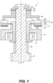
- Fig. 1 is a cross-sectional view illustrating a vibration wave motor according to embodiment 1.
- Fig. 2 is a perspective view illustrating that part of a vibrator 10 and a mover 20 are cut out.
- Embodiment 1 employs a configuration where the vibrator 10 side is fixed, and the mover 20 which is one example of a relative motion member is driven.
- the mover 20 is made of a light metal such as aluminum. Surface treatment for improving abrasion resistance is performed on a sliding surface 20a of the mover 20.
- the vibrator 10 includes an electromechanical transducer (abbreviated as a piezoelectric body below) 11 which is, for example, a piezoelectric element or an electrostrictive element which converts electric energy into mechanical energy, and an elastic body 12 to which the piezoelectric body 11 is bonded, and the vibrator 10 produces a traveling vibration wave.
- an electromechanical transducer abbreviated as a piezoelectric body below
- 11 which is, for example, a piezoelectric element or an electrostrictive element which converts electric energy into mechanical energy
- an elastic body 12 to which the piezoelectric body 11 is bonded, and the vibrator 10 produces a traveling vibration wave.
- the elastic body 12 is made of a metal material whose resonance sharpness is great, and has an annular shape.
- the piezoelectric body 11 is bonded to one surface (bonding surface 12f) of the elastic body 12, and grooves 12b are engraved on a side opposite to this bonding surface 12f. Furthermore, distal ends of protrusion portions (portions without the grooves 12b) 12c become driving surfaces 12a, and are placed in pressure contact with the sliding surface 20a of the mover 20. Lubricant surface treatment is performed on the driving surfaces 12a.
- a part at which the grooves 12b of the elastic body 12 are not engraved is a base part 12d, and a flange 12e is extended from the base part 12d to an inner diameter side.
- An innermost diameter part of the flange 12e is fixed to a fixing member 13.
- a sliding member such as a coating film or lubricant plating is applied to the protrusion portions 12c of the elastic body 12 to cover the entire protrusion portions 12c.
- the piezoelectric body 11 is made of a material which is a material free of lead and whose main ingredients are potassium-sodium niobate.
- a flexible printed circuit board (FPC) 14 is bonded to a surface (opposite bonding surface) of the piezoelectric body 11 on an opposite side to the bonding surface 12f of the elastic body 12 to transmit a drive signal, and extends to a circuit board.
- Electrodes are arranged on the opposite bonding surface, and form a two-group structure which is grouped into two phases (an A phase and a B phase) along a circumferential direction. The electrodes are arranged in each phase such that the electrodes are alternately polarized per 1/2 wavelength, and an interval corresponding to a 1/4 wavelength is secured between the A phase and the B phase.
- An output shaft 21 is coupled to the mover 20 by means of a rubber member 22 and a stopper member 23 inserted to so as to fit to a D cut of the output shaft 21. Furthermore, the output shaft 21 and the stopper member 23 are fixed by an E clip 24, and rotate together with the mover 20.
- the rubber member 22 between the stopper member 23 and the mover 20 has a function of coupling the mover 20 and the stopper member 23 by adhesiveness of a rubber, and is suitably, for example, a butyl rubber which has a vibration absorption function of preventing vibration from the mover 20 from transmitting to the output shaft 21.
- a pressurizing member 25 is provided between an output gear 41 of the output shaft 21 and a bearing 27. According to this structure, the mover 20 is placed in pressure contact with the driving surface 12a of the elastic body 12.
- Fig. 3 is a block diagram illustrating a driving device 300 of a vibration wave motor 1 according to embodiment 1.
- the driving device 300 includes a control unit 301, an oscillation unit 302, a phase unit 303, an amplification unit 304, the vibration wave motor 1, and a detection unit 305.
- the control unit 301 is electrically connected with a CPU 310 in a lens barrel 110 (see Fig. 13 ) or of a camera main body.
- the control unit 301 controls driving of the vibration wave motor 1 based on a drive command from the CPU 310 in the lens barrel 110 or of the camera main body.
- the control unit 301 receives a detection signal from the detection unit 305, obtains position information and speed information based on a value of this detection signal, and controls a frequency of the oscillation unit 302 such that positioning is performed at a target position.
- the oscillation unit 302 generates a drive signal of a desired frequency according to a command of the control unit 301.
- the phase unit 303 divides the drive signal generated by the oscillation unit 302 into two drive signals of different phases.
- the amplification unit 304 respectively boosts the two drive signals divided by the phase unit 303 to desired voltages.
- the drive signals from the amplification unit 304 are transmitted to the vibration wave motor 1, the vibrator 10 produces a traveling wave when applied these drive signals, and the mover 20 is driven.
- the detection unit 305 includes, for example, an optical encoder or a magnetic encoder, and detects a position and a speed of a driving object driven by driving of the mover 20, and transmits a detection value as an electric signal to the control unit 301.
- the control unit 301 issues the drive command
- the oscillation unit 302 generates a drive signal.
- This drive signal is divided into two drive signals whose phases are different by 90 degrees by the phase unit 303, and is amplified to desired voltages by the amplification unit 304.
- the amplified drive signals are applied to the piezoelectric body 11 of the vibration wave motor 1, and the piezoelectric body 11 is excited (vibrated).
- the elastic body 12 causes quaternary bending vibration.
- the piezoelectric body 11 is grouped into the A phase and the B phase, and the drive signals are respectively applied to the A phase and the B phase.
- Positional phases of quaternary bending vibration caused by the A phase and quaternary bending vibration caused by the B phase are shifted by a 1/4 wavelength. Furthermore, phases of an A phase drive signal and a B phase drive signal are shifted by 90 degrees, and therefore the two bending vibrations are synthesized, and become traveling waves of four waves.
- the optical encoder which is the detection unit 305 is arranged on a driving body driven by driving of the mover 20, and the optical encoder generates an electric pulse to transmit to the control unit 301.
- the control unit 301 can obtain a current position and a current speed based on a signal of this electric pulse.
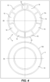
- Fig. 4 is an explanatory view illustrating the piezoelectric body 11 according to embodiment 1.
- Fig. 4(a) is a view illustrating a top surface 11A of the piezoelectric body 11
- Fig. 4(b) is a view illustrating a back surface 11B of the piezoelectric body 11.
- Fig. 5 is an explanatory view illustrating the vibrator 10 according to embodiment 1.
- Fig. 5(a) is a view illustrating a side surface of the vibrator 10
- Fig. 5(b) is a view illustrating the vibrator 10 seen from a side of the top surface 11A of the piezoelectric body 11.
- electrodes 16 are grouped into two phases (the A phase and the B phase) along the circumferential direction. In each phase, the electrodes 16 are alternately polarized per 1/2 wavelength, and the electrodes 16 are printed on a base 18 of the piezoelectric body 11 by a silver paste such that an interval corresponding to a 1/4 wavelength is secured between the A phase and the B phase.
- the electrodes 16 may be metal plating such as NiP or gold.
- the base 18 of the piezoelectric body 11 is formed by a lead-free material whose main ingredients are sodium-potassium niobate.
- the back surface 11B has a shape on which an electrode 19 which is not like an electrode pattern of the electrodes 16 is printed by a silver paste, and in which the base 18 of the piezoelectric body 11 appears at an outer circumferential side and an inner circumferential side.
- the electrode 19 may be metal plating such as NiP or gold.
- the back surface 11B is bonded to the elastic body 12 by a cold curing adhesive.
- the FPC 14 is bonded to the top surface 11A to transmit drive signals from the driving device 300, and is connected with the driving device 300.
- a GND wire of the FPC 14 is bonded to the electrodes 16 of the 1/4 wavelength, is bonded to the electrodes 16 of the 1/4 wavelength and a metal part of the elastic body 12 crossing using an unillustrated conductive coating, and thereby is grounded to the metal part of the elastic body 12.
- the material of the piezoelectric body 11 is a piezoelectric ceramic made of sodium-potassium niobate metal oxides, and a following material and manufacturing method are used, for example.
- the material of the piezoelectric body 11 is expressed by following chemical formula (1).
- the material of this piezoelectric body 11 has a very little temperature characteristics of a relative permittivity. More specifically, a change percentage of the relative permittivity is 500 [ppm/°C] or less in absolute value in a range of -40°C to 170°C, that is, is in a range of -500 to +500 [ppm/°C]. Consequently, it is possible to make the temperature characteristics of an electrostatic capacitance of the piezoelectric body 11 a little very much.
- sodium carbonate and potassium carbonate in the material makes pH of a slurry at a time of mixing and at a time of pulverization strong alkaline.
- sodium niobate and potassium niobate which are prepared by a hydrothermal synthesis method and whose grain sizes are nano sizes are used for the material. Consequently, it is possible to make pH weak alkaline.
- sodium and niobium, and potassium and niobium of sodium niobate and potassium niobate whose composition ratios (x) are in a range of 1.00 ⁇ x ⁇ 1.01 may be used. According to a manufacturing method described below, the range of (x) was changed to check a difference between a case where (x) was 1.00 and a case where (x) was 1.01.
- a and B were respectively changed in a following range based on chemical formula (1-C-E) (Li A (Na B K (1-B) ) (1-A) NbO 3 as a composition of a niobium non-lead piezoelectric ceramic material to carry out the manufacturing method.
- 0.055 mol to 0.1 mol of lithium carbonate, 0.05 mol to 0.1 mol of barium carbonate, 0.05 mol to 0.1 mol of zirconium oxide, 0.05 mol to 0.1 mol of titanium oxide, 0.005 mol to 0.01 mol of bismuth oxide, and 0.005 mol to 0.01 mol of iron oxide were blended at this rate.
- a blending amount of a composition of a material ⁇ in Fig. 6 which was blended such that an entire blending amount was in a scale of 100 g and a preparation method thereof will be described as a typical example.
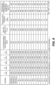
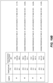
- Fig. 6 is a table illustrating constants (A to E), an electromechanical coupling factor, a relative permittivity, a piezoelectric constant, and temperature characteristics of the relative permittivity (change percentage) of chemical formula (1) of each material.
- the temperature characteristics of the relative permittivity were measured in two temperature ranges (-40 to 170°C and 0 to 60°C).
- the electromechanical coupling factor is larger, electric energy is more efficiently converted into mechanical energy.
- 0.1 wt% of Cu was added to a material ⁇ .
- a mechanical quality factor (described later with reference to Fig. 11 ) improves.
- blending amount of the composition of the material ⁇ in Fig. 6 and the preparation method thereof 0.057 mol of lithium carbonate, 0.05 mol of barium carbonate, 0.0415 mol of zirconium oxide, 0.0085 mol of titanium oxide, 0.005 mol of bismuth oxide, and 0.005 mol of iron oxide were blended at this rate, and were mixed and milled in 300 ml of water for 24 hours by a ball mill to prepare a primary mixing and milling solution. Furthermore, compared to the blending amount of the composition of the material ⁇ in Fig. 6 , blending amounts of compositions of A to E in other Nos. are determined based on varying percentage proportions with respect to the material ⁇ .
- this dried material was subjected to temporary calcination twice in a range of 700°C to 800°C.
- the first temporary calcination was performed at 800°C for two hours by using an electric furnace, resulting temporary calcination powder was then milled in 300 ml of water for 24 hours by the ball mill, was dried at 85°C for 48 hours by using a thermostat bath, and, after primary temporary calcination milled dried powder was prepared, temporary calcination was performed again.
- a temperature range of second temporary calcination was 800°C which was the same temperature condition as that of the first temporary calcination, and the time was two hours.
- the first temporary calcination and the second temporary calcination may be performed under a condition that calcination temperatures are different.
- a calcination atmosphere condition was that calcination was performed in atmospheric air in the present embodiment, calcination can be also performed in an atmosphere other than air. For example, manufacturing can be performed in an oxygen atmosphere.
- a temporary calcination powder milling method was a method such as a ball mill or a bead mill, and second calcination powder was milled in 300 ml of water for 24 hours by the ball mill such that a grain size of second temporary calcination milled dried powder became 1 ⁇ m or less, and was dried at 85°C for 48 hours by using the thermostat bath to prepare second temporary calcination milled dried powder.
- the second temporary calcination milled dried powder and 10 wt% of a binder were mixed, were let pass a #40 mesh screen, and were dried at 110°C for one hour by using the thermostat bath to prepare granulated powder of granules.
- the granulated powder was loaded to a mold of ⁇ 15 mm, was pressurized by using a hydraulic press machine (200 ton press), and was molded such that a molding density ( ⁇ ) was approximately 2.3 g/cm 3 to 2.6 g/cm 3 and the thickness of a molded material was 1.5 mm.
- a time for pressurization was 1 to 10 seconds.
- the molding density ( ⁇ ) was approximately 2.3 to 2.6 g/cm 3
- molding was performed by changing the molding density in a range of 2.6 g/cm 3 which was an upper limit to 2.3 g/cm 3 which was a lower limit.
- a result of molding showed that 2.5 g/cm 3 was optimal.
- degreasing is performed in a temperature range of 700°C to 800°C by using the electric furnace after molding, it is preferable to maintain the temperature range at 700°C for four hours, and then perform calcination in a calcination temperature range of 1100°C to 1250°C in the embodiment. Calcination was performed at 1200°C in the embodiment. Calcination was performed in an atmosphere such as air at a time of calcination.
- This element with the silver electrodes was applied a voltage of 4.0 kV/mm in an insulating oil (silicon oil) of 50°C for 10 minutes, and polarized to manufacture a niobium non-lead piezoelectric ceramic.
- the niobium non-lead piezoelectric ceramic material was left for 24 hours after polarization processing, and measured by a resonance-antiresonance method by using an impedance analyzer (device 4294A manufactured by Agilent Technologies, Inc.). Furthermore, an equivalent piezoelectric constant was measured by using a d 33 meter (ZJ-43 manufactured by Institute of Acoustics, Chinese Academy of Sciences).
- the niobium non-lead piezoelectric ceramic according to the present embodiment was obtained by this manufacturing method.
- the electromechanical coupling factor, the relative permittivity, the piezoelectric constant, the temperature characteristics of the relative permittivity and temperature characteristics of a Curie point of the resulting niobium non-lead piezoelectric ceramic were measured by a following method.
- Fig. 7 is a view of temperature characteristics of a relative permittivity.
- Fig. 7 illustrates a change in the relative permittivity at a time when measurement was performed by raising a temperature in a temperature range from -40°C to 170°C and dropping a temperature from 170°C to -40°C to the contrary.
- a difference between values of the relative permittivity according to the present embodiment at the time of the temperature rise when measurement was performed from the low temperature side of -40°C and at the time of the temperature drop from when measurement was performed from the high temperature side of 170°C was maximum 38 and small, and a hysteresis value of the relative permittivity before and after phase transition was in a range of 32 to 38.
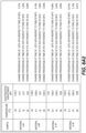
- Fig. 8A1 is a graph illustrating temperature characteristics of electrostatic capacitances of materials ⁇ and ⁇ of the piezoelectric body 11 according to embodiment 1 (part 1).
- Fig. 8A2 is a graph illustrating temperature characteristics of electrostatic capacitances of materials ⁇ and ⁇ of the piezoelectric body 11 according to embodiment 1 (part 2).
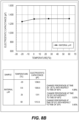
- Fig. 8B is a graph illustrating temperature characteristics of an electrostatic capacitance of the material ⁇ of the piezoelectric body 11 according to embodiment 1.
- Figs. 8A1 is a graph illustrating temperature characteristics of electrostatic capacitances of materials ⁇ and ⁇ of the piezoelectric body 11 according to embodiment 1 (part 1).
- Fig. 8A2 is a graph illustrating temperature characteristics of electrostatic capacitances of materials ⁇ and ⁇ of the piezoelectric body 11 according to embodiment 1 (part 2).
- Fig. 8B is a graph illustrating temperature characteristics of an electrostatic capacitance of the material ⁇ of the piezo
- a temperature higher than -20°C and equal to or less than 0°C is a low temperature range
- a temperature higher than 0°C and equal to or less than 25°C is a normal temperature range
- a temperature higher than 25°C and equal to or less than 60°C is a high temperature range.
- fluctuation of the material ⁇ is approximately 2% at 0°C, and approximately 10% at -20°C.
- Fluctuation of the material ⁇ is approximately 4% at 0°C, and approximately 11% at -20°C. Fluctuation of the material ⁇ is approximately 1% at 0°C, and approximately 5% at -20°C.
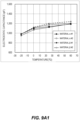
- Fig. 9A1 is a graph illustrating temperature characteristics of electrostatic capacitances of the vibrator 10 in a case where the materials ⁇ and ⁇ are used (part 1).
- Fig. 9A2 is a graph illustrating temperature characteristics of electrostatic capacitances of the vibrator 10 in a case where the materials ⁇ and ⁇ are used (part 2).
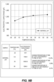
- Fig. 9B is a graph illustrating temperature characteristics of an electrostatic capacitance of the vibrator 10 according to embodiment 1 in a case where the material ⁇ is used.
- Fig. 10A is a graph illustrating a measured consumption current at each temperature for the vibration wave motor 1 according to embodiment 1 and a vibration wave motor which is a PZT-mounted product (part 1).
- Fig. 10B is a graph illustrating a measured consumption current at each temperature for the vibration wave motor 1 according to embodiment 1 and a vibration wave motor which is a PZT-mounted product (part 2).
- a drive voltage was set to 70 [Vrms] per measurement to measure a current input to the vibration wave motor at a time when the vibration wave motor was driven at a predetermined rotation speed. It is found that the vibration wave motor 1 on which the materials ⁇ , ⁇ , and ⁇ are mounted has little temperature characteristics of the input current.
- FIG. 11 is an explanatory view illustrating an equivalent circuit of the vibrator 10 of the vibration wave motor 1.
- An equivalent circuit 1100 of the vibrator 10 includes an electrostatic capacitance Cd of the piezoelectric body 11, an equivalent inductance L, an equivalent capacitance C, and a resonant resistance R.
- a current Ia of the vibrator 10 is a sum of a current Ib (following equation (2)) to a component of the electrostatic capacitance Cd of the piezoelectric body 11 and a current Ic (following equation (3)) to an LCR series side.
- Ib E / 1 / j ⁇ Cd where E represents a drive voltage, ⁇ represents an angular frequency, and f represents a frequency of a drive signal.
- Ic E R + j ⁇ L + 1 / ⁇ C where la ⁇ lb holds in state of 1/j ⁇ Cd ⁇ R+j( ⁇ L+1/ ⁇ C).
- a vibration wave motor is driven at a driving frequency which is slightly apart toward a high frequency side from a resonance frequency at which an impedance of an equivalent circuit 900 is minimum and an antiresonance frequency at which the impedance of the equivalent circuit 900 is maximal.
- a value of 1/ ⁇ Cd which is a denominator of the current Ib is much smaller than a value of R+( ⁇ L-1/ ⁇ C) which is a denominator of the current Ic, and therefore the current Ia input to the vibrator 10 takes the substantially same value as that of the current Ib. That is, a consumption current of the vibrator 10 substantially depends on whether the value of the electrostatic capacitance Cd of the piezoelectric body 11 is large or small.
- a general vibration wave motor is designed to match an impedance of a driving device and an impedance of a vibration wave motor.
- a voltage of a drive signal (drive voltage E) changes. Therefore, when the electrostatic capacitance Cd of the piezoelectric body 11 is fluctuated by an environmental temperature, the voltage of the drive signal also fluctuates.
- the vibration wave motor on which PZT is mounted adjusts the voltage to an appropriate voltage at a normal temperature
- the drive voltage at a low temperature and a drive voltage at a high temperature significantly differ. More specifically, a phenomenon that, compared to the voltage at the time of the normal temperature, the drive voltage is high at the time of the low temperature, and the drive voltage is low at the time of the high temperature occurs. A higher drive voltage than an originally necessary drive voltage is set at the time of the low temperature, and the high voltage undermines driving efficiency of the drive circuit itself.
- a change in the electrostatic capacitance of the vibration wave motor 1 according to embodiment 1 at the time of the low temperature and at the time of the high temperature is a little compared to the PZT-mounted product, so that it is possible to substantially make fluctuation of the drive voltage a very little, and driving efficiency of the driving device 300 itself is improved.
- Q in following equation (4) represents a mechanical quality factor.
- Values of the equivalent inductance L and the equivalent capacitance C influence resonance characteristics of the vibrator 10.
- the mechanical quality factor Q is a scale which indicates resonance characteristics, and a higher value of the mechanical quality factor Q indicates better resonance characteristics.
- the mechanical quality factor Q becomes larger as an Lm value becomes larger.
- the material ⁇ illustrated in Fig. 6 provides the larger mechanical quality factor Q, and improved resonance characteristics.
- the vibration wave motor 1 according to embodiment 1 has a little temperature characteristics of a drivable voltage.
- Fig. 12 is a table showing a lowest voltage (referred to a drivable voltage below) of a drive signal which can drive the vibration wave motor 1 according to embodiment 1.
- the vibration wave motor 1 cannot be driven at the drive voltage E which is lower than a value of the drivable voltage.
- the drivable voltages change little in a range to 0 to 50°C in temperature at which the electrostatic capacitances change little.
- the drivable voltages become higher a little at -20°C, fluctuation amounts are a very little compared to a case where the PZT is mounted.
- An experiment conducted by the inventors of the present invention shows that the drivable voltage and the electrostatic capacitance of the vibrator 10 correlate. This reason will be described.
- An electromechanical coupling factor Kvn of the vibrator 10 is expressed by following equation (5) as a quantity converted from electric energy Ui stored in the vibrator 10 into mechanical energy Ut which is strain energy of vibration.
- Kvn Ut/Ui 0.5
- E represents a drive voltage
- ⁇ represents an angular frequency
- Cdv represents an electrostatic capacitance of the vibrator 10.
- a state where the vibration wave motor 1 is drivable is a state where strain energy reaches a certain threshold or more.
- the electromechanical coupling factor Kvn and ⁇ take certain values, the strain energy of the certain threshold depends on a value of the electrostatic capacitance Cdv of the vibrator 10 and a voltage value to be applied.
- the electrostatic capacitance Cdv of the vibrator 10 of the PZT-mounted product is fluctuated by a temperature, and therefore a drivable voltage changes accompanying the fluctuation.
- the drivable voltage at -20°C at which the drivable voltage becomes high is set as a reference point to set the drive voltage E to the PZT-mounted product.
- a difference between the drive voltages E and the drivable voltages at a normal temperature and a high temperature becomes significant, and therefore an extra current larger than an originally necessary current is input.
- the temperature characteristics of the drivable voltage of the vibration wave motor 1 according to embodiment 1 are a little, a difference between the drive voltage and the drivable voltage at each temperature does not change so much, and therefore a substantially necessary current is input at each temperature.
- Fig. 13 is a cross-sectional view illustrating a lens barrel 110 on which the vibration wave motor 1 is mounted.
- the lens barrel 110 includes an outer fixed cylinder 31, an inner fixed cylinder 32, and the vibration wave motor 1.
- the outer fixed cylinder 31 has, for example, a cylindrical shape, and covers an outer circumferential part of the lens barrel 110.
- the outer fixed cylinder 31 includes a protrusion piece 31a which protrudes from an inner circumferential surface of the outer fixed cylinder 31 to an optical axis OA.
- the protrusion piece 31a supports the inner fixed cylinder 32.
- the inner fixed cylinder 32 has, for example, a cylindrical shape, and is provided on an inner circumferential side compared to the outer fixed cylinder 31.
- the vibration wave motor 1 is provided between the outer fixed cylinder 31 and the inner fixed cylinder 32.
- a first lens group L1, a second lens group L2, a third lens group L3, and a fourth lens group L4 are arranged on the identical optical axis OA in order from a subject side.
- the third lens group L3 is an AF lens held by an annular Auto Focus (AF) ring 119.
- the first lens group L1, the second lens group L2 and the fourth lens group L4 are fixed to the inner fixed cylinder 32.
- the third lens group L3 is configured to be able to move in a direction of the optical axis OA (referred to as an optical axis direction below) with respect to the inner fixed cylinder 32 when the AF ring 119 moves.
- the vibration wave motor 1 is attached to a gear unit module 113.
- the gear unit module 113 is attached to the inner fixed cylinder 32 of the lens barrel 110.
- the output gear 41 of the vibration wave motor 1 transmits a rotational motion to a cum ring 116 via a deceleration gear 115 of the gear unit module 113, and the cum ring 116 is rotated and driven.
- a key groove 117 is engraved in the cum ring 116 diagonally in a circumferential direction.
- the AF ring 119 includes a fixing pin 118.
- the fixing pin 118 is inserted in the key groove 117.
- the driving device 300 illustrated in Fig. 2 is provided between the outer fixed cylinder 31 and the inner fixed cylinder 32 of the lens barrel 110 to drive and control the above-described vibration wave motor 1, and detect a rotational speed.
- the vibration wave motor 1 can make temperature characteristics of a consumption current a little compared to the PZT-mounted product. Furthermore, the change in the electrostatic capacitance Cdv of the vibrator 10 at the time of the low temperature and at the time of the high temperature is a little compared to the PZT-mounted product, so that it is possible to substantially make fluctuation of the drive voltage E a very little, and the driving efficiency of the driving device 300 itself is improved. Furthermore, the electrostatic capacitance Cdv of the vibrator 10 is fluctuated little by an environmental temperature compared to the PZT-mounted product, so that it is possible to make a temperature change in a drivable voltage of the vibration wave motor 1 a little.
- Embodiment 2 is an example where the vibration wave motor 1 according to embodiment 1 is an annular type vibration wave motor.
- the same components as those of embodiment 1 will be assigned the same reference numerals, and description thereof will be omitted.
- Fig. 14 is a cross-sectional view illustrating a lens barrel on which the annular type vibration wave motor according to embodiment 2 is mounted.
- a lens barrel 200 includes the outer fixed cylinder 31 and the inner fixed cylinder 32, and adopts a mechanism that a motor unit including an annular type vibration wave motor 210 is fixed to the outer fixed cylinder 31 and the inner fixed cylinder 32.
- the driving device 300 is provided between the outer fixed cylinder 31 and the inner fixed cylinder 32 of the lens barrel 200 to drive and control the vibration wave motor 210, and detect a rotational speed.
- the driving device 300 matches an impedance of the driving device 300 and an impedance of the vibration wave motor.
- the vibrator 211 includes the piezoelectric body 11 which is made of the same sodium-potassium niobate metal oxides as those of embodiment 1, and an elastic body 214 to which the piezoelectric body 11 has been bonded. Although the vibrator 211 produces traveling waves, traveling waves of nine waves will be described as an example in embodiment 2.
- the elastic body 214 is made of a metal material whose resonance sharpness is great.
- the shape of the elastic body 214 is an annular shape. Grooves are engraved on an opposite surface of the elastic body 214 to which the piezoelectric body 11 is bonded. A reason for engraving the grooves is to place the piezoelectric body 11 side close to neutral surfaces of the traveling waves as much as possible, and thereby amplify the amplitudes of the traveling waves of a driving surface 216a.
- a surface of a part which is not provided with the grooves is the driving surface 216a, and is placed in pressure contact with a mover 220.
- a lubricant coating film is applied to the surface of the driving surface 216a of the elastic body 214 to secure driving performance and improve durability.
- the piezoelectric body 11 is grouped into two phases (the A phase and the B phase) along the circumferential direction similar to embodiment 1, elements are arranged in each phase such that the elements are alternately polarized per 1/2 wavelength, and an interval corresponding to a 1/4 wavelength is secured between the A phase and the B phase.
- the piezoelectric body 11 is formed by the same material as that of embodiment 1, and is formed by a material whose temperature characteristics of a relative permittivity are a very little, that is, a material whose temperature characteristics of the electrostatic capacitance Cd are a little.
- the non-woven fabric 252 is, for example, a felt, and is arranged under the piezoelectric body 11 to prevent vibration of the vibrator 211 from transmitting to the pressurizing member 250.
- the pressurizing member 250 is arranged under a pressure plate (not illustrated) to generate a pressurizing force.
- the pressurizing member 250 is a disc spring.
- the pressurizing member 250 may be a coil spring or a wave spring instead of the disc spring.
- a retention ring 251 is fixed to a fixing member 223, and thereby the pressurizing member 250 is held.
- the mover 220 is made of a light metal such as aluminum, and a sliding material is provided on a surface of a sliding surface to improve abrasion resistance.
- a vibration absorption member 243 such as a rubber is arranged on the mover 220 to absorb longitudinal vibration of the mover 220, and an output transmission member 242 is arranged thereon.
- a pressurizing direction and a radial direction of the output transmission member 242 are regulated by a bearing 253 provided to the fixing member 223, and thereby a pressurizing direction and a radial direction of the mover 220 are regulated.
- the output transmission member 242 includes a protrusion part 241, the protrusion part 241 fits with a fork connected with a cum ring 315, and the cum ring 315 rotates together with rotation of the output transmission member 242.
- a key groove 317 is engraved in the cum ring 315 diagonally in the circumferential direction, a fixing pin 318 provided to an AF ring 319 fits to the key groove 317, and, when the cum ring 315 is rotated and driven, the AF ring 319 is driven in the direction straight to the optical axis direction, and can stop at a desired position.
- the retention ring 251 is attached to the fixing member 223 by a screw, and, by attaching this retention ring 251, the output transmission member 242 to the mover 220, the vibrator 211 and the pressurizing member 250 can be formed as one motor unit.
- the vibration wave motor 210 which uses the vibrator 211 according to embodiment 2 also has a very little temperature characteristics of the consumption current compared to the PZT-mounted product. Furthermore, the impedance of the driving device 300 and the impedance of the vibration wave motor 210 are matched. A change in the electrostatic capacitance Cdv of the vibrator 10 of the vibration wave motor 210 according to embodiment 2 at the time of the low temperature and at the time of the high temperature is a little compared to the PZT-mounted product, so that it is possible to substantially make fluctuation of the drive voltage E a very little, and driving efficiency of the driving device 300 itself is improved. Furthermore, what is the same as embodiment 1 is that the electrostatic capacitance Cdv of the vibrator 10 is fluctuated little by an environmental temperature, and therefore a temperature change in a drivable voltage of the vibration wave motor 210 is also a little.
- a vibration wave motor according to embodiment 3 is a type whose vibrator includes only the piezoelectric body 11, and whose driving rail which is a relative motion member is linearly driven.
- the same components as those of embodiment 1 and embodiment 2 will be assigned the same reference numerals, and description thereof will be omitted.
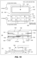
- Fig. 15 is an explanatory view illustrating the vibrator according to embodiment 3.
- Fig. 15(A) is a front view and a back view of a vibrator 1500
- Fig. 15(B) is a schematic perspective view of the vibrator 1500
- Fig. 15(C) is an explanatory view illustrating an implementation example of the vibrator 1500.
- the vibration wave motor 1 according to embodiment 3 is a type whose vibrator 1500 includes only the piezoelectric body 11, and whose driving rail 1550 which is a relative motion member is linearly driven.
- the vibrator 1500 includes the piezoelectric body 11 made of the same sodium-potassium niobate metal oxides as those of embodiment 1, and sliding members 1560 which are installed at end parts.
- the vibrator 1500 is pressurized against the driving rail 1550 by a pressurizing spring 1525.
- a linear guide 1527 is provided between a fixing member 1513 and the driving rail 1550, a linear guide fixing part 1527a is fixed to the fixing member 1513, a movable part 1527b is coupled to the driving rail 1550, and the driving rail 1550 can be moved only in left and right directions in the figure.
- An elliptical motion is produced at positions of sliding members 1560 of the vibrator 1500 to linearly drive the driving rail 1550.
- the vibrator 1500 adopts a two-layer structure, one electrode 1510 is provided on a first surface 1501 in a first layer, and one electrode 1520 having the same shape is provided on a second surface 1502 on an opposite side, too.
- An A phase drive signal is input to the electrode 1510 on the first surface 1501 side, and the electrode 1520 of the second surface 1502 is a GND.
- the vibrator 1500 produces a standing wave of longitudinal primary mode vibration.
- Electrodes 1531 to 1534 are provided on a third surface 1503 in the second layer, and polarization directions of the four electrodes 1531 to 1534 are respectively alternate.
- One electrode 1540 having the same shape as that of the first layer is provided on a fourth surface 1504 on an opposite side, too.
- a B phase drive signal is input to the electrodes 1531 to 1534 on the third surface 1503 side, and the electrode 1540 on the fourth surface 1504 side is a GND.
- the vibrator 1500 produces a standing wave of bending secondary mode vibration.
- the second surface 1502 which is the GND in the first layer and the fourth surface 1504 which is the GND in the second layer are bonded to form a common GND.
- a groove part 1505 is provided at a center part of the vibrator 1500, and the pressurizing spring 1525 fits this groove to prevent displacement of a pressurizing position, and support the driving rail 1550 in a longitudinal direction.
- the sliding members 1560 are made of an engineer plastic material of good abrasion resistance, and are provided at places in the figure which are positions at which an amplitude of the standing wave of the longitudinal primary mode vibration maximizes and an amplitude of a standing wave of the bending secondary mode vibration maximizes.
- Fig. 16 is an explanatory view illustrating a driving principal of the vibrator 1500 according to embodiment 3.
- Fig. 16(a) to (e) will be described in chronological order below.
- t represents a time
- a vertical axis indicates a voltage
- a horizontal axis indicates a time.
- a voltage of the A phase is 0, and a voltage of the B phase is minus.
- displacement of the longitudinal primary vibration is zero, and the bending secondary vibration which displaces a C point in a minus direction and displaces a D point in a plus direction occurs.
- t 3: The voltage of the A phase is 0, and the voltage of the B phase is plus. In this case, displacement of the longitudinal primary vibration is zero, and the bending secondary vibration which displaces the C point in the plus direction and displaces the D point in the minus direction occurs.
- elliptical motions occur at the C point and the D point at which the sliding members 1560 are attached as illustrated at a right end in Fig. 16 .
- the mover is placed in pressure contact with these sliding members 1560, the mover is applied a friction force of the elliptical motions and driven.
- the same material as that of embodiment 1 is used for the piezoelectric body 11, so that it is possible to obtain the same effect as that of embodiment 1.
- Embodiment 4 describes an example where the vibration wave motor 1 is applied to a dust proof device including a camera.
- the same components as those of embodiment 1 will be assigned the same reference numerals, and description thereof will be omitted.
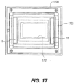
- Fig. 17 is an explanatory view illustrating an example of the dust proof device according to embodiment 4.
- the dust proof device 1700 is installed near an imaging element 1701, and vibration of the piezoelectric body 11 vibrates an optical filter 1702 to remove dust adhered to the optical filter 1702.
- the dust proof device 1700 according to embodiment 4 also includes the piezoelectric body 11 and the driving device 300.
- a task that a voltage of driving vibration from the driving device 300 fluctuates depending on the value of the electrostatic capacitance Cd of the piezoelectric body 11 is the same as that of the vibrator 10 of the vibration wave motor 1.
- the same material as that of embodiment 1 is used for the piezoelectric body 11, so that it is possible to obtain the same effect as that of embodiment 1.
- the present invention is not limited to the content above, and the content above may be freely combined. Also, other aspects considered to be within the scope of the technical concept of the present invention are included in the scope of the present invention.
- vibration wave motor 10 vibrator, 11 piezoelectric body, 12 elastic body, 12a driving surfaces, 12f bonding surface, 20 mover, 20a sliding surface, 300 driving device, 110 lens barrel, 200 lens barrel, 210 vibration wave motor, 211 vibrator, 214 elastic body, 216a driving surface, 220 mover, 1500 vibrator, 1700 dust proof device
Landscapes
- Physics & Mathematics (AREA)
- Chemical & Material Sciences (AREA)
- Engineering & Computer Science (AREA)
- Optics & Photonics (AREA)
- General Physics & Mathematics (AREA)
- Ceramic Engineering (AREA)
- Materials Engineering (AREA)
- Organic Chemistry (AREA)
- Structural Engineering (AREA)
- Manufacturing & Machinery (AREA)
- General Electrical Machinery Utilizing Piezoelectricity, Electrostriction Or Magnetostriction (AREA)
- Lens Barrels (AREA)
- Camera Bodies And Camera Details Or Accessories (AREA)
- Compositions Of Oxide Ceramics (AREA)
Abstract
Description
- The present application claims priority from Japanese patent application
JP 2020-97583 filed on June 4, 2020 - The disclosure relates to a vibrator and a vibration wave motor.
- As disclosed in
JP 01-017354 B2 JP 01-017354 B2 - A vibrator of a first disclosure comprises an electromechanical transducer which is a piezoelectric ceramic made of sodium-potassium niobate metal oxides and whose temperature characteristics of a relative permittivity is 500 [ppm/°C] or less in absolute value in a temperature range from -40°C to 170°C, wherein excitation of the electromechanical transducer produces a vibration wave.
- A vibrator of a second disclosure comprises an electromechanical transducer which is a piezoelectric ceramic made of sodium-potassium niobate metal oxides and whose temperature characteristics of a relative permittivity is 390 [ppm/°C] or less in absolute value in a temperature range from 0°C to 60°C, wherein excitation of the electromechanical transducer produces a vibration wave.
- A vibration wave motor of a third disclosure comprises: the vibrator according to any one of the first and second disclosure; and a relative motion member which includes a sliding surface placed in pressure contact with a driving surface of the vibrator, and is caused to make a relative motion by the vibration wave.
-
-
Fig. 1 is a cross-sectional view illustrating a vibration wave motor according toembodiment 1. -
Fig. 2 is a perspective view illustrating that part of a vibrator and a mover are cut out. -
Fig. 3 is a block diagram illustrating a driving device of a vibration wave motor according toembodiment 1. -
Fig. 4 is an explanatory view illustrating the piezoelectric body according toembodiment 1. -
Fig. 5 is an explanatory view illustrating the vibrator according toembodiment 1. -
Fig. 6 is a table illustrating constants (A to E), an electromechanical coupling factor, a relative permittivity, a piezoelectric constant, and temperature characteristics of the relative permittivity (change percentage) of chemical formula (1) of each material. -
Fig. 7 is a view of temperature characteristics of a relative permittivity. -
Fig. 8A1 is a graph illustrating temperature characteristics of electrostatic capacitances of materials α and β of the piezoelectric body according to embodiment 1 (part 1). -
Fig. 8A2 is a graph illustrating temperature characteristics of electrostatic capacitances of materials α and β of the piezoelectric body according to embodiment 1 (part 2). -
Fig. 8B is a graph illustrating temperature characteristics of an electrostatic capacitance of the material γ of thepiezoelectric body 11 according toembodiment 1. -
Fig. 9A1 is a graph illustrating temperature characteristics of electrostatic capacitances of the vibrator in a case where the materials α and β are used (part 1). -
Fig. 9A2 is a graph illustrating temperature characteristics of electrostatic capacitances of the vibrator in a case where the materials α and β are used (part 2). -
Fig. 9B is a graph illustrating temperature characteristics of an electrostatic capacitance of thevibrator 10 according toembodiment 1 in a case where the material γ is used. -
Fig. 10A is a graph illustrating a measured consumption current at each temperature for the vibration wave motor according toembodiment 1 and a vibration wave motor which is a PZT-mounted product (part 1). -
Fig. 10B is a graph illustrating a measured consumption current at each temperature for the vibration wave motor according toembodiment 1 and a vibration wave motor which is a PZT-mounted product (part 2). -
Fig. 11 is an explanatory view illustrating an equivalent circuit of the vibrator of the vibration wave motor. -
Fig. 12 is a table showing a lowest voltage (referred to a drivable voltage below) of a drive signal which can drive the vibration wave motor according toembodiment 1. -
Fig. 13 is a cross-sectional view illustrating a lens barrel on which the vibration wave motor is mounted. -
Fig. 14 is a cross-sectional view illustrating a lens barrel on which the annular type vibration wave motor according toembodiment 2 is mounted. -
Fig. 15 is an explanatory view illustrating the vibrator according toembodiment 3. -
Fig. 16 is an explanatory view illustrating a driving principal of the vibrator according toembodiment 3. -
Fig. 17 is an explanatory view illustrating an example of the dust proof device according toembodiment 4. -
Fig. 18 is a graph illustrating an example of temperature characteristics of an electrostatic capacitance of PZT (made by Fuji Ceramics Corporation) which is a material of the piezoelectric body prepared for the vibration wave motor. -
Fig. 19A is a graph illustrating an example of temperature characteristics of an electrostatic capacitance of the vibrator of the vibration wave motor in a case where the PZT inFig. 18 is a piezoelectric body material (part 1). -
Fig. 19B is a graph illustrating an example of temperature characteristics of an electrostatic capacitance of the vibrator of the vibration wave motor in a case where the PZT inFig. 18 is a piezoelectric body material (part 2). -
Fig. 20 is a graph obtained by measuring a current input at each temperature for the vibration wave motor of a PZT-mounted product. - A vibration wave motor produces a traveling wave on a driving surface of an elastic body by using expansion and contraction of a piezoelectric body, this traveling wave causes an elliptical motion on the driving surface, and a mover placed in pressure contact with a crest of the elliptical motion is driven. Features of the vibration wave motor include that the vibration wave motor has a high torque even in a case of low rotation, and in a case where the vibration wave motor is mounted on a driving device, a gear of the driving device can be omitted. Consequently, by canceling gear noise, it is possible to achieve noise reduction, and improve positioning accuracy.
- A vibrator of this vibration wave motor generally includes an electromechanical transducer (abbreviated as a piezoelectric body below) and an elastic body. The piezoelectric body is generally formed by a material such as lead zirconate titanate which is commonly called PZT.
-
Fig. 18 is a graph illustrating an example of temperature characteristics of an electrostatic capacitance of PZT (made by Fuji Ceramics Corporation) which is a material of the piezoelectric body prepared for the vibration wave motor. It is found that the electrostatic capacitance has an inclination of approximately 4.4 [pF/°C] (≈ 2750 [ppm/°C]) with respect to a temperature. -
Fig. 19A is a graph illustrating an example of temperature characteristics of an electrostatic capacitance of the vibrator of the vibration wave motor in a case where the PZT inFig. 18 is a piezoelectric body material (part 1).Fig. 19B is a graph illustrating an example of temperature characteristics of an electrostatic capacitance of the vibrator of the vibration wave motor in a case where the PZT inFig. 18 is a piezoelectric body material (part 2). It is found that the electrostatic capacitances have an inclination of approximately 6.2 [pF/°C] (≈ 4430 [ppm/°C]) with respect to a temperature. This inclination indicates that, for example, when the temperature becomes lower, the electrostatic capacitance of the piezoelectric body decreases more, and, when the temperature becomes higher, the electrostatic capacitance of the piezoelectric body increases more. -
Fig. 20 is a graph obtained by measuring a current input at each temperature for the vibration wave motor of a PZT-mounted product. At each time of measurement, a drive voltage was set to 70 [Vrms], and a current input to the vibration wave motor at a time when the vibration wave motor was driven at a predetermined rotation speed was measured. A phenomenon is that, while an input current decreases more when the temperature becomes lower, the input current increases more when the temperature becomes higher compared to a current at a normal temperature. This phenomenon matches with temperature characteristics of an electrostatic capacitance value of the vibrator illustrated inFigs. 19A and19B . - Although the electrostatic capacitance of the vibrator decreases more when the temperature becomes lower, an impedance increases, and therefore the input current decreases, the electrostatic capacitance of the vibrator increases more when the temperature becomes higher, the impedance decreases, and therefore the input current increases accordingly. Accordingly, when the temperature becomes higher, the electrostatic capacitance of the vibrator increases more, and therefore the vibration wave motor cannot be efficiently driven.
- While the vibration wave motor generates a driving force according to a drive signal supplied from a driving device, and can obtain desired driving performance under a certain drive signal condition such as an appropriate voltage value, and the voltage of this drive signal changes depending on the electrostatic capacitance of the piezoelectric body.
- There is also a driving device which includes a matching circuit which matches an impedance of a driving circuit which drives a piezoelectric motor and an impedance of the piezoelectric motor. The PZT has great temperature characteristics as illustrated in
Fig. 18 , and therefore even when this driving device adjusts a voltage to an appropriate voltage at a normal temperature, a driving voltage at a low temperature and a driving voltage at a high temperature significantly differ. Therefore, it is not possible to sufficiently exhibit driving performance (driving efficiency or a driving force) of the vibration wave motor. - According to the present embodiment, a material free of lead is applied to the piezoelectric body to improve driving performance of the vibration wave motor in order to deal with environmental issues. The vibrator and the vibration wave motor according to the present embodiment will be described below citing
embodiment 1 toembodiment 4. -
Fig. 1 is a cross-sectional view illustrating a vibration wave motor according toembodiment 1.Fig. 2 is a perspective view illustrating that part of avibrator 10 and amover 20 are cut out.Embodiment 1 employs a configuration where thevibrator 10 side is fixed, and themover 20 which is one example of a relative motion member is driven. Themover 20 is made of a light metal such as aluminum. Surface treatment for improving abrasion resistance is performed on a slidingsurface 20a of themover 20. - The
vibrator 10 includes an electromechanical transducer (abbreviated as a piezoelectric body below) 11 which is, for example, a piezoelectric element or an electrostrictive element which converts electric energy into mechanical energy, and anelastic body 12 to which thepiezoelectric body 11 is bonded, and thevibrator 10 produces a traveling vibration wave. - The
elastic body 12 is made of a metal material whose resonance sharpness is great, and has an annular shape. Thepiezoelectric body 11 is bonded to one surface (bonding surface 12f) of theelastic body 12, andgrooves 12b are engraved on a side opposite to thisbonding surface 12f. Furthermore, distal ends of protrusion portions (portions without thegrooves 12b) 12c become drivingsurfaces 12a, and are placed in pressure contact with the slidingsurface 20a of themover 20. Lubricant surface treatment is performed on the drivingsurfaces 12a. - A part at which the
grooves 12b of theelastic body 12 are not engraved is abase part 12d, and aflange 12e is extended from thebase part 12d to an inner diameter side. An innermost diameter part of theflange 12e is fixed to a fixingmember 13. A sliding member such as a coating film or lubricant plating is applied to theprotrusion portions 12c of theelastic body 12 to cover theentire protrusion portions 12c. - Although described in detail later, the
piezoelectric body 11 is made of a material which is a material free of lead and whose main ingredients are potassium-sodium niobate. A flexible printed circuit board (FPC) 14 is bonded to a surface (opposite bonding surface) of thepiezoelectric body 11 on an opposite side to thebonding surface 12f of theelastic body 12 to transmit a drive signal, and extends to a circuit board. Electrodes are arranged on the opposite bonding surface, and form a two-group structure which is grouped into two phases (an A phase and a B phase) along a circumferential direction. The electrodes are arranged in each phase such that the electrodes are alternately polarized per 1/2 wavelength, and an interval corresponding to a 1/4 wavelength is secured between the A phase and the B phase. - An
output shaft 21 is coupled to themover 20 by means of arubber member 22 and astopper member 23 inserted to so as to fit to a D cut of theoutput shaft 21. Furthermore, theoutput shaft 21 and thestopper member 23 are fixed by anE clip 24, and rotate together with themover 20. - The
rubber member 22 between thestopper member 23 and themover 20 has a function of coupling themover 20 and thestopper member 23 by adhesiveness of a rubber, and is suitably, for example, a butyl rubber which has a vibration absorption function of preventing vibration from themover 20 from transmitting to theoutput shaft 21. A pressurizingmember 25 is provided between anoutput gear 41 of theoutput shaft 21 and abearing 27. According to this structure, themover 20 is placed in pressure contact with the drivingsurface 12a of theelastic body 12. -
Fig. 3 is a block diagram illustrating adriving device 300 of avibration wave motor 1 according toembodiment 1. Thedriving device 300 includes acontrol unit 301, anoscillation unit 302, aphase unit 303, anamplification unit 304, thevibration wave motor 1, and adetection unit 305. Thecontrol unit 301 is electrically connected with aCPU 310 in a lens barrel 110 (seeFig. 13 ) or of a camera main body. - The
control unit 301 controls driving of thevibration wave motor 1 based on a drive command from theCPU 310 in thelens barrel 110 or of the camera main body. Thecontrol unit 301 receives a detection signal from thedetection unit 305, obtains position information and speed information based on a value of this detection signal, and controls a frequency of theoscillation unit 302 such that positioning is performed at a target position. - The
oscillation unit 302 generates a drive signal of a desired frequency according to a command of thecontrol unit 301. Thephase unit 303 divides the drive signal generated by theoscillation unit 302 into two drive signals of different phases. Theamplification unit 304 respectively boosts the two drive signals divided by thephase unit 303 to desired voltages. The drive signals from theamplification unit 304 are transmitted to thevibration wave motor 1, thevibrator 10 produces a traveling wave when applied these drive signals, and themover 20 is driven. - The
detection unit 305 includes, for example, an optical encoder or a magnetic encoder, and detects a position and a speed of a driving object driven by driving of themover 20, and transmits a detection value as an electric signal to thecontrol unit 301. - Next, an operation of the
vibration wave motor 1 will be described. When thecontrol unit 301 issues the drive command, theoscillation unit 302 generates a drive signal. This drive signal is divided into two drive signals whose phases are different by 90 degrees by thephase unit 303, and is amplified to desired voltages by theamplification unit 304. The amplified drive signals are applied to thepiezoelectric body 11 of thevibration wave motor 1, and thepiezoelectric body 11 is excited (vibrated). When thepiezoelectric body 11 is excited, theelastic body 12 causes quaternary bending vibration. Thepiezoelectric body 11 is grouped into the A phase and the B phase, and the drive signals are respectively applied to the A phase and the B phase. - Positional phases of quaternary bending vibration caused by the A phase and quaternary bending vibration caused by the B phase are shifted by a 1/4 wavelength. Furthermore, phases of an A phase drive signal and a B phase drive signal are shifted by 90 degrees, and therefore the two bending vibrations are synthesized, and become traveling waves of four waves.
- An elliptical motion occurs at a crest of a traveling wave. Thus, the
mover 20 placed in pressure contact with the drivingsurface 12a is driven causing friction by this elliptical motion. The optical encoder which is thedetection unit 305 is arranged on a driving body driven by driving of themover 20, and the optical encoder generates an electric pulse to transmit to thecontrol unit 301. Thecontrol unit 301 can obtain a current position and a current speed based on a signal of this electric pulse. -
Fig. 4 is an explanatory view illustrating thepiezoelectric body 11 according toembodiment 1.Fig. 4(a) is a view illustrating atop surface 11A of thepiezoelectric body 11, andFig. 4(b) is a view illustrating aback surface 11B of thepiezoelectric body 11.Fig. 5 is an explanatory view illustrating thevibrator 10 according toembodiment 1.Fig. 5(a) is a view illustrating a side surface of thevibrator 10, andFig. 5(b) is a view illustrating thevibrator 10 seen from a side of thetop surface 11A of thepiezoelectric body 11. - In the
top surface 11A,electrodes 16 are grouped into two phases (the A phase and the B phase) along the circumferential direction. In each phase, theelectrodes 16 are alternately polarized per 1/2 wavelength, and theelectrodes 16 are printed on abase 18 of thepiezoelectric body 11 by a silver paste such that an interval corresponding to a 1/4 wavelength is secured between the A phase and the B phase. Theelectrodes 16 may be metal plating such as NiP or gold. Thebase 18 of thepiezoelectric body 11 is formed by a lead-free material whose main ingredients are sodium-potassium niobate. - The
back surface 11B has a shape on which anelectrode 19 which is not like an electrode pattern of theelectrodes 16 is printed by a silver paste, and in which thebase 18 of thepiezoelectric body 11 appears at an outer circumferential side and an inner circumferential side. Theelectrode 19 may be metal plating such as NiP or gold. Theback surface 11B is bonded to theelastic body 12 by a cold curing adhesive. - Furthermore, the
FPC 14 is bonded to thetop surface 11A to transmit drive signals from the drivingdevice 300, and is connected with thedriving device 300. A GND wire of theFPC 14 is bonded to theelectrodes 16 of the 1/4 wavelength, is bonded to theelectrodes 16 of the 1/4 wavelength and a metal part of theelastic body 12 crossing using an unillustrated conductive coating, and thereby is grounded to the metal part of theelastic body 12. - Hereinafter, a material of the
piezoelectric body 11 will be described. The material of thepiezoelectric body 11 is a piezoelectric ceramic made of sodium-potassium niobate metal oxides, and a following material and manufacturing method are used, for example. The material of thepiezoelectric body 11 is expressed by following chemical formula (1).
(1-C-E)(LiA(NaBK(1-B))(1-A)NbO3+CBa(ZrDTi(1-D))O3+EBiFeO3
where 0 < A < 0.2, 0.4 ≤ B ≤ 0.6, 0 < C ≤ 0.1, 0 < D < 1.00, and 0 < E < 0.02 hold ... (1) - The material of this
piezoelectric body 11 has a very little temperature characteristics of a relative permittivity. More specifically, a change percentage of the relative permittivity is 500 [ppm/°C] or less in absolute value in a range of -40°C to 170°C, that is, is in a range of -500 to +500 [ppm/°C]. Consequently, it is possible to make the temperature characteristics of an electrostatic capacitance of the piezoelectric body 11 a little very much. - Use of sodium carbonate and potassium carbonate in the material makes pH of a slurry at a time of mixing and at a time of pulverization strong alkaline. Hence, according to the present embodiment, sodium niobate and potassium niobate which are prepared by a hydrothermal synthesis method and whose grain sizes are nano sizes are used for the material. Consequently, it is possible to make pH weak alkaline.
- Furthermore, sodium and niobium, and potassium and niobium of sodium niobate and potassium niobate whose composition ratios (x) are in a range of 1.00 ≤ x ≤ 1.01 may be used. According to a manufacturing method described below, the range of (x) was changed to check a difference between a case where (x) was 1.00 and a case where (x) was 1.01.
- The manufacturing method will be more specifically described below. A and B were respectively changed in a following range based on chemical formula (1-C-E)(LiA(NaBK(1-B))(1-A)NbO3 as a composition of a niobium non-lead piezoelectric ceramic material to carry out the manufacturing method.
- 0.055 ≤ A ≤ 0.1
- 0.4 ≤ B ≤ 0.6
- Barium zirconate titanate and bismuth ferrite were added thereto to prepare the composition.
(1-C-E)(LiA(NaBK(1-B))(1-A)NbO3+CBa(ZrDTi(1-D))O3+EBiFeO3
(0.055 ≤ A ≤ 0.1, 0.4 ≤ B ≤ 0.6, 0.05 ≤ C ≤ 0.1, 0.17 ≤ D ≤ 0.83, and 0.005 ≤ E ≤ 0.01) - According to a blending method according to the present embodiment, 0.055 mol to 0.1 mol of lithium carbonate, 0.05 mol to 0.1 mol of barium carbonate, 0.05 mol to 0.1 mol of zirconium oxide, 0.05 mol to 0.1 mol of titanium oxide, 0.005 mol to 0.01 mol of bismuth oxide, and 0.005 mol to 0.01 mol of iron oxide were blended at this rate.
- Furthermore, a blending amount of a composition of a material α in
Fig. 6 which was blended such that an entire blending amount was in a scale of 100 g, and a preparation method thereof will be described as a typical example. -
Fig. 6 is a table illustrating constants (A to E), an electromechanical coupling factor, a relative permittivity, a piezoelectric constant, and temperature characteristics of the relative permittivity (change percentage) of chemical formula (1) of each material. The temperature characteristics of the relative permittivity were measured in two temperature ranges (-40 to 170°C and 0 to 60°C). When the electromechanical coupling factor is larger, electric energy is more efficiently converted into mechanical energy. In addition to these ingredients, 0.1 wt% of Cu was added to a material γ. Thus, a mechanical quality factor (described later with reference toFig. 11 ) improves. - According to the blending amount of the composition of the material α in
Fig. 6 and the preparation method thereof, 0.057 mol of lithium carbonate, 0.05 mol of barium carbonate, 0.0415 mol of zirconium oxide, 0.0085 mol of titanium oxide, 0.005 mol of bismuth oxide, and 0.005 mol of iron oxide were blended at this rate, and were mixed and milled in 300 ml of water for 24 hours by a ball mill to prepare a primary mixing and milling solution. Furthermore, compared to the blending amount of the composition of the material α inFig. 6 , blending amounts of compositions of A to E in other Nos. are determined based on varying percentage proportions with respect to the material α. - 0.444 mol of sodium niobate and 0.444 mol of potassium niobate prepared by the hydrothermal synthesis method by being subjected to solvothermal reaction with this primary mixing and milling solution at 150°C to 300°C for 1 to 12 hours was blended to prepare a mixture. This mixture was mixed and milled in 300 ml of water at a room temperature for 24 hours by the ball mill again to prepare a secondary mixing and milling solution. Subsequently, this secondary mixing and milling solution was dried at 85°C for 48 hours in a state where the secondary mixing and milling solution was weak alkaline at pH 8.9 to pH 9.8 equal to or less than
pH 10 to prepare a dried material. - Next, this dried material was subjected to temporary calcination twice in a range of 700°C to 800°C. The first temporary calcination was performed at 800°C for two hours by using an electric furnace, resulting temporary calcination powder was then milled in 300 ml of water for 24 hours by the ball mill, was dried at 85°C for 48 hours by using a thermostat bath, and, after primary temporary calcination milled dried powder was prepared, temporary calcination was performed again.
- A temperature range of second temporary calcination was 800°C which was the same temperature condition as that of the first temporary calcination, and the time was two hours. In this regard, the first temporary calcination and the second temporary calcination may be performed under a condition that calcination temperatures are different. Although a calcination atmosphere condition was that calcination was performed in atmospheric air in the present embodiment, calcination can be also performed in an atmosphere other than air. For example, manufacturing can be performed in an oxygen atmosphere.
- A temporary calcination powder milling method was a method such as a ball mill or a bead mill, and second calcination powder was milled in 300 ml of water for 24 hours by the ball mill such that a grain size of second temporary calcination milled dried powder became 1 µm or less, and was dried at 85°C for 48 hours by using the thermostat bath to prepare second temporary calcination milled dried powder.
- Subsequently, the second temporary calcination milled dried powder and 10 wt% of a binder were mixed, were let pass a #40 mesh screen, and were dried at 110°C for one hour by using the thermostat bath to prepare granulated powder of granules.
- After granulation, the granulated powder was loaded to a mold of ϕ15 mm, was pressurized by using a hydraulic press machine (200 ton press), and was molded such that a molding density (ρ) was approximately 2.3 g/cm3 to 2.6 g/cm3 and the thickness of a molded material was 1.5 mm. A time for pressurization was 1 to 10 seconds. Note that the molding density (ρ) was approximately 2.3 to 2.6 g/cm3, and molding was performed by changing the molding density in a range of 2.6 g/cm3 which was an upper limit to 2.3 g/cm3 which was a lower limit. A result of molding showed that 2.5 g/cm3 was optimal.
- Although degreasing is performed in a temperature range of 700°C to 800°C by using the electric furnace after molding, it is preferable to maintain the temperature range at 700°C for four hours, and then perform calcination in a calcination temperature range of 1100°C to 1250°C in the embodiment. Calcination was performed at 1200°C in the embodiment. Calcination was performed in an atmosphere such as air at a time of calcination.
- After calcination, a calcined material was machined to a thickness of T = 0.5 mm by using a grinding machine (6 BN, HAMAI and
number # 800 abrasive), and a silver paste (SR-2099 made by Namics Corporation) was applied to a surface of a machined element by a screen printing method to provide the element with silver electrodes at 800°C by using the electric furnace. This element with the silver electrodes was applied a voltage of 4.0 kV/mm in an insulating oil (silicon oil) of 50°C for 10 minutes, and polarized to manufacture a niobium non-lead piezoelectric ceramic. - Furthermore, according to a method for measuring a niobium non-lead piezoelectric ceramic material, the niobium non-lead piezoelectric ceramic material was left for 24 hours after polarization processing, and measured by a resonance-antiresonance method by using an impedance analyzer (device 4294A manufactured by Agilent Technologies, Inc.). Furthermore, an equivalent piezoelectric constant was measured by using a d33 meter (ZJ-43 manufactured by Institute of Acoustics, Chinese Academy of Sciences).
- The niobium non-lead piezoelectric ceramic according to the present embodiment was obtained by this manufacturing method. The electromechanical coupling factor, the relative permittivity, the piezoelectric constant, the temperature characteristics of the relative permittivity and temperature characteristics of a Curie point of the resulting niobium non-lead piezoelectric ceramic were measured by a following method.
- A method for measuring the temperature characteristics of the relative permittivity of the niobium non-lead piezoelectric ceramic material prepared by the manufacturing method according to the present embodiment will be described.
- The
piezoelectric body 11 having a shape whose diameter was ϕ10×T0.5 mm and obtained herein was left for 24 hours, a small ultra-low incubator (MC-811, ESPEC CORP.) was used, and an electrostatic capacitance at a time when a frequency was 1 kHz and a voltage was 0.5 V was measured by using the impedance analyzer (device 4294A manufactured by Agilent Technologies, Inc.) every 10°C from -40°C to 170°C and from 170°C to -40°C to calculate the relative permittivity. A result thereof is shown inFig. 7 . -
Fig. 7 is a view of temperature characteristics of a relative permittivity.Fig. 7 illustrates a change in the relative permittivity at a time when measurement was performed by raising a temperature in a temperature range from -40°C to 170°C and dropping a temperature from 170°C to -40°C to the contrary. A difference between values of the relative permittivity according to the present embodiment at the time of the temperature rise when measurement was performed from the low temperature side of -40°C and at the time of the temperature drop from when measurement was performed from the high temperature side of 170°C was maximum 38 and small, and a hysteresis value of the relative permittivity before and after phase transition was in a range of 32 to 38. - It is generally known that, in a case of a material such as crystal, a relative permittivity changes little in a temperature range of -40°C to 170°C. Even according to the present embodiment, it has been confirmed that a material having sufficient practicality can be provided in this range as shown in
Fig. 7 . -
Fig. 8A1 is a graph illustrating temperature characteristics of electrostatic capacitances of materials α and β of thepiezoelectric body 11 according to embodiment 1 (part 1).Fig. 8A2 is a graph illustrating temperature characteristics of electrostatic capacitances of materials α and β of thepiezoelectric body 11 according to embodiment 1 (part 2).Fig. 8B is a graph illustrating temperature characteristics of an electrostatic capacitance of the material γ of thepiezoelectric body 11 according toembodiment 1. InFigs. 8A and8B , for example, a temperature higher than -20°C and equal to or less than 0°C is a low temperature range, a temperature higher than 0°C and equal to or less than 25°C is a normal temperature range, and a temperature higher than 25°C and equal to or less than 60°C is a high temperature range. Regarding changes in the electrostatic capacitances of the materials α, β, and γ from the time of the low temperature to the time of the high temperature, in a case where 60°C serves as a reference point, fluctuation of the material α is approximately 2% at 0°C, and approximately 10% at -20°C. Fluctuation of the material β is approximately 4% at 0°C, and approximately 11% at -20°C. Fluctuation of the material γ is approximately 1% at 0°C, and approximately 5% at -20°C. -
Fig. 9A1 is a graph illustrating temperature characteristics of electrostatic capacitances of thevibrator 10 in a case where the materials α and β are used (part 1).Fig. 9A2 is a graph illustrating temperature characteristics of electrostatic capacitances of thevibrator 10 in a case where the materials α and β are used (part 2).Fig. 9B is a graph illustrating temperature characteristics of an electrostatic capacitance of thevibrator 10 according toembodiment 1 in a case where the material γ is used. Regarding changes in the electrostatic capacitances of thevibrator 10 from the time of the low temperature to the time of the high temperature, in a case where 60°C serves as a reference point, fluctuation of the material α is approximately 8% at 0°C, and approximately 18% at -20°C. Fluctuation of the material β is approximately 10% at 0°C, and approximately 20% at -20°C. Fluctuation of the material γ is approximately 6% at 0°C, and approximately 16% at -20°C. These fluctuations are much smaller than 25% at 0°C and 31 to 33% at -20°C which are change percentages in a case where PZT is mounted. -
Fig. 10A is a graph illustrating a measured consumption current at each temperature for thevibration wave motor 1 according toembodiment 1 and a vibration wave motor which is a PZT-mounted product (part 1).Fig. 10B is a graph illustrating a measured consumption current at each temperature for thevibration wave motor 1 according toembodiment 1 and a vibration wave motor which is a PZT-mounted product (part 2). A drive voltage was set to 70 [Vrms] per measurement to measure a current input to the vibration wave motor at a time when the vibration wave motor was driven at a predetermined rotation speed. It is found that thevibration wave motor 1 on which the materials α, β, and γ are mounted has little temperature characteristics of the input current. Upon comparison with the temperature characteristics of the input current of the PZT-mounted product illustrated inFigs. 19A and19B , it is found that thevibration wave motor 1 can be more efficiently driven than the PZT-mounted product particularly at a high temperature. This phenomenon is caused by the temperature characteristics of the electrostatic capacitance of thevibrator 10 as described above. This phenomenon will be described with reference toFig. 11 . -
Fig. 11 is an explanatory view illustrating an equivalent circuit of thevibrator 10 of thevibration wave motor 1. Anequivalent circuit 1100 of thevibrator 10 includes an electrostatic capacitance Cd of thepiezoelectric body 11, an equivalent inductance L, an equivalent capacitance C, and a resonant resistance R. A current Ia of thevibrator 10 is a sum of a current Ib (following equation (2)) to a component of the electrostatic capacitance Cd of thepiezoelectric body 11 and a current Ic (following equation (3)) to an LCR series side.

- Generally, a vibration wave motor is driven at a driving frequency which is slightly apart toward a high frequency side from a resonance frequency at which an impedance of an equivalent circuit 900 is minimum and an antiresonance frequency at which the impedance of the equivalent circuit 900 is maximal. Under a condition of this driving frequency, a value of 1/ωCd which is a denominator of the current Ib is much smaller than a value of R+(ωL-1/ωC) which is a denominator of the current Ic, and therefore the current Ia input to the
vibrator 10 takes the substantially same value as that of the current Ib. That is, a consumption current of thevibrator 10 substantially depends on whether the value of the electrostatic capacitance Cd of thepiezoelectric body 11 is large or small. - Hence, when the electrostatic capacitance of the
vibrator 10 changes due to a temperature, an impedance also changes, and a current to be input changes. The electrostatic capacitance of the products on which the materials α, β, and γ are mounted increases little even when a temperature becomes high, and therefore a current to be input also increases little. - Furthermore, a general vibration wave motor is designed to match an impedance of a driving device and an impedance of a vibration wave motor. Hence, when the value of the electrostatic capacitance Cd of the
piezoelectric body 11 changes, a voltage of a drive signal (drive voltage E) changes. Therefore, when the electrostatic capacitance Cd of thepiezoelectric body 11 is fluctuated by an environmental temperature, the voltage of the drive signal also fluctuates. - Even when the vibration wave motor on which PZT is mounted adjusts the voltage to an appropriate voltage at a normal temperature, the drive voltage at a low temperature and a drive voltage at a high temperature significantly differ. More specifically, a phenomenon that, compared to the voltage at the time of the normal temperature, the drive voltage is high at the time of the low temperature, and the drive voltage is low at the time of the high temperature occurs. A higher drive voltage than an originally necessary drive voltage is set at the time of the low temperature, and the high voltage undermines driving efficiency of the drive circuit itself. A change in the electrostatic capacitance of the
vibration wave motor 1 according toembodiment 1 at the time of the low temperature and at the time of the high temperature is a little compared to the PZT-mounted product, so that it is possible to substantially make fluctuation of the drive voltage a very little, and driving efficiency of thedriving device 300 itself is improved. - Q in following equation (4) represents a mechanical quality factor. Values of the equivalent inductance L and the equivalent capacitance C influence resonance characteristics of the
vibrator 10. The mechanical quality factor Q is a scale which indicates resonance characteristics, and a higher value of the mechanical quality factor Q indicates better resonance characteristics. The mechanical quality factor Q becomes larger as an Lm value becomes larger. Compared to the material β, the material γ illustrated inFig. 6 provides the larger mechanical quality factor Q, and improved resonance characteristics.
- Furthermore, it is also found that the
vibration wave motor 1 according toembodiment 1 has a little temperature characteristics of a drivable voltage. -
Fig. 12 is a table showing a lowest voltage (referred to a drivable voltage below) of a drive signal which can drive thevibration wave motor 1 according toembodiment 1. Thevibration wave motor 1 cannot be driven at the drive voltage E which is lower than a value of the drivable voltage. In a case of each of the materials α, β, and γ, the drivable voltages change little in a range to 0 to 50°C in temperature at which the electrostatic capacitances change little. Although the drivable voltages become higher a little at -20°C, fluctuation amounts are a very little compared to a case where the PZT is mounted. - An experiment conducted by the inventors of the present invention shows that the drivable voltage and the electrostatic capacitance of the
vibrator 10 correlate. This reason will be described. An electromechanical coupling factor Kvn of thevibrator 10 is expressed by following equation (5) as a quantity converted from electric energy Ui stored in thevibrator 10 into mechanical energy Ut which is strain energy of vibration.
- Almost all of the electric energy Ui stored in the
vibrator 10 is stored in thepiezoelectric body 11. On the other hand, energy Pf stored in thepiezoelectric body 11 is as expressed by following equation (6).
- E represents a drive voltage, ω represents an angular frequency, and Cdv represents an electrostatic capacitance of the
vibrator 10. A state where thevibration wave motor 1 is drivable is a state where strain energy reaches a certain threshold or more. When the electromechanical coupling factor Kvn and ω take certain values, the strain energy of the certain threshold depends on a value of the electrostatic capacitance Cdv of thevibrator 10 and a voltage value to be applied. However, it is thought that the electrostatic capacitance Cdv of thevibrator 10 of the PZT-mounted product is fluctuated by a temperature, and therefore a drivable voltage changes accompanying the fluctuation. - When driving is performed using a drive signal of a certain voltage, the drivable voltage at -20°C at which the drivable voltage becomes high is set as a reference point to set the drive voltage E to the PZT-mounted product. However, a difference between the drive voltages E and the drivable voltages at a normal temperature and a high temperature becomes significant, and therefore an extra current larger than an originally necessary current is input. On the other hand, the temperature characteristics of the drivable voltage of the
vibration wave motor 1 according toembodiment 1 are a little, a difference between the drive voltage and the drivable voltage at each temperature does not change so much, and therefore a substantially necessary current is input at each temperature. -
Fig. 13 is a cross-sectional view illustrating alens barrel 110 on which thevibration wave motor 1 is mounted. Thelens barrel 110 includes an outerfixed cylinder 31, an innerfixed cylinder 32, and thevibration wave motor 1. The outerfixed cylinder 31 has, for example, a cylindrical shape, and covers an outer circumferential part of thelens barrel 110. The outerfixed cylinder 31 includes aprotrusion piece 31a which protrudes from an inner circumferential surface of the outer fixedcylinder 31 to an optical axis OA. Theprotrusion piece 31a supports the inner fixedcylinder 32. The inner fixedcylinder 32 has, for example, a cylindrical shape, and is provided on an inner circumferential side compared to the outer fixedcylinder 31. Thevibration wave motor 1 is provided between the outer fixedcylinder 31 and the inner fixedcylinder 32. - In the inner fixed
cylinder 32, a first lens group L1, a second lens group L2, a third lens group L3, and a fourth lens group L4 are arranged on the identical optical axis OA in order from a subject side. The third lens group L3 is an AF lens held by an annular Auto Focus (AF)ring 119. The first lens group L1, the second lens group L2 and the fourth lens group L4 are fixed to the inner fixedcylinder 32. The third lens group L3 is configured to be able to move in a direction of the optical axis OA (referred to as an optical axis direction below) with respect to the inner fixedcylinder 32 when theAF ring 119 moves. - The
vibration wave motor 1 is attached to agear unit module 113. Thegear unit module 113 is attached to the inner fixedcylinder 32 of thelens barrel 110. Theoutput gear 41 of thevibration wave motor 1 transmits a rotational motion to acum ring 116 via adeceleration gear 115 of thegear unit module 113, and thecum ring 116 is rotated and driven. - A
key groove 117 is engraved in thecum ring 116 diagonally in a circumferential direction. TheAF ring 119 includes a fixingpin 118. The fixingpin 118 is inserted in thekey groove 117. When thecum ring 116 is rotated and driven in a state where the fixingpin 118 is inserted in thekey groove 117, theAF ring 119 is driven in a direction straight to the optical axis OA direction, and can stop at a desired position. Thedriving device 300 illustrated inFig. 2 is provided between the outer fixedcylinder 31 and the inner fixedcylinder 32 of thelens barrel 110 to drive and control the above-describedvibration wave motor 1, and detect a rotational speed. - Consequently, the
vibration wave motor 1 according toembodiment 1 can make temperature characteristics of a consumption current a little compared to the PZT-mounted product. Furthermore, the change in the electrostatic capacitance Cdv of thevibrator 10 at the time of the low temperature and at the time of the high temperature is a little compared to the PZT-mounted product, so that it is possible to substantially make fluctuation of the drive voltage E a very little, and the driving efficiency of thedriving device 300 itself is improved. Furthermore, the electrostatic capacitance Cdv of thevibrator 10 is fluctuated little by an environmental temperature compared to the PZT-mounted product, so that it is possible to make a temperature change in a drivable voltage of the vibration wave motor 1 a little. -
Embodiment 2 is an example where thevibration wave motor 1 according toembodiment 1 is an annular type vibration wave motor. The same components as those ofembodiment 1 will be assigned the same reference numerals, and description thereof will be omitted. -
Fig. 14 is a cross-sectional view illustrating a lens barrel on which the annular type vibration wave motor according toembodiment 2 is mounted. Alens barrel 200 includes the outer fixedcylinder 31 and the inner fixedcylinder 32, and adopts a mechanism that a motor unit including an annular typevibration wave motor 210 is fixed to the outer fixedcylinder 31 and the inner fixedcylinder 32. Thedriving device 300 is provided between the outer fixedcylinder 31 and the inner fixedcylinder 32 of thelens barrel 200 to drive and control thevibration wave motor 210, and detect a rotational speed. Thedriving device 300 matches an impedance of thedriving device 300 and an impedance of the vibration wave motor. - Next, a configuration of the
vibration wave motor 210 will be described. Thevibrator 211 includes thepiezoelectric body 11 which is made of the same sodium-potassium niobate metal oxides as those ofembodiment 1, and anelastic body 214 to which thepiezoelectric body 11 has been bonded. Although thevibrator 211 produces traveling waves, traveling waves of nine waves will be described as an example inembodiment 2. - The
elastic body 214 is made of a metal material whose resonance sharpness is great. The shape of theelastic body 214 is an annular shape. Grooves are engraved on an opposite surface of theelastic body 214 to which thepiezoelectric body 11 is bonded. A reason for engraving the grooves is to place thepiezoelectric body 11 side close to neutral surfaces of the traveling waves as much as possible, and thereby amplify the amplitudes of the traveling waves of a drivingsurface 216a. A surface of a part which is not provided with the grooves is the drivingsurface 216a, and is placed in pressure contact with amover 220. A lubricant coating film is applied to the surface of the drivingsurface 216a of theelastic body 214 to secure driving performance and improve durability. - The
piezoelectric body 11 is grouped into two phases (the A phase and the B phase) along the circumferential direction similar toembodiment 1, elements are arranged in each phase such that the elements are alternately polarized per 1/2 wavelength, and an interval corresponding to a 1/4 wavelength is secured between the A phase and the B phase. Thepiezoelectric body 11 is formed by the same material as that ofembodiment 1, and is formed by a material whose temperature characteristics of a relative permittivity are a very little, that is, a material whose temperature characteristics of the electrostatic capacitance Cd are a little. - Under the
piezoelectric body 11, anon-woven fabric 252 and a pressurizingmember 250 are arranged. Thenon-woven fabric 252 is, for example, a felt, and is arranged under thepiezoelectric body 11 to prevent vibration of thevibrator 211 from transmitting to the pressurizingmember 250. - The pressurizing
member 250 is arranged under a pressure plate (not illustrated) to generate a pressurizing force. Inembodiment 2, the pressurizingmember 250 is a disc spring. The pressurizingmember 250 may be a coil spring or a wave spring instead of the disc spring. Aretention ring 251 is fixed to a fixingmember 223, and thereby the pressurizingmember 250 is held. - The
mover 220 is made of a light metal such as aluminum, and a sliding material is provided on a surface of a sliding surface to improve abrasion resistance. Avibration absorption member 243 such as a rubber is arranged on themover 220 to absorb longitudinal vibration of themover 220, and anoutput transmission member 242 is arranged thereon. - A pressurizing direction and a radial direction of the
output transmission member 242 are regulated by abearing 253 provided to the fixingmember 223, and thereby a pressurizing direction and a radial direction of themover 220 are regulated. Theoutput transmission member 242 includes aprotrusion part 241, theprotrusion part 241 fits with a fork connected with acum ring 315, and thecum ring 315 rotates together with rotation of theoutput transmission member 242. - A
key groove 317 is engraved in thecum ring 315 diagonally in the circumferential direction, a fixingpin 318 provided to anAF ring 319 fits to thekey groove 317, and, when thecum ring 315 is rotated and driven, theAF ring 319 is driven in the direction straight to the optical axis direction, and can stop at a desired position. - The
retention ring 251 is attached to the fixingmember 223 by a screw, and, by attaching thisretention ring 251, theoutput transmission member 242 to themover 220, thevibrator 211 and the pressurizingmember 250 can be formed as one motor unit. - What is the same as
embodiment 1 is that thevibration wave motor 210 which uses thevibrator 211 according toembodiment 2 also has a very little temperature characteristics of the consumption current compared to the PZT-mounted product. Furthermore, the impedance of thedriving device 300 and the impedance of thevibration wave motor 210 are matched. A change in the electrostatic capacitance Cdv of thevibrator 10 of thevibration wave motor 210 according toembodiment 2 at the time of the low temperature and at the time of the high temperature is a little compared to the PZT-mounted product, so that it is possible to substantially make fluctuation of the drive voltage E a very little, and driving efficiency of thedriving device 300 itself is improved. Furthermore, what is the same asembodiment 1 is that the electrostatic capacitance Cdv of thevibrator 10 is fluctuated little by an environmental temperature, and therefore a temperature change in a drivable voltage of thevibration wave motor 210 is also a little. - A vibration wave motor according to
embodiment 3 is a type whose vibrator includes only thepiezoelectric body 11, and whose driving rail which is a relative motion member is linearly driven. The same components as those ofembodiment 1 andembodiment 2 will be assigned the same reference numerals, and description thereof will be omitted. -
Fig. 15 is an explanatory view illustrating the vibrator according toembodiment 3.Fig. 15(A) is a front view and a back view of avibrator 1500,Fig. 15(B) is a schematic perspective view of thevibrator 1500, andFig. 15(C) is an explanatory view illustrating an implementation example of thevibrator 1500. - The
vibration wave motor 1 according toembodiment 3 is a type whosevibrator 1500 includes only thepiezoelectric body 11, and whosedriving rail 1550 which is a relative motion member is linearly driven. Thevibrator 1500 includes thepiezoelectric body 11 made of the same sodium-potassium niobate metal oxides as those ofembodiment 1, and slidingmembers 1560 which are installed at end parts. - The
vibrator 1500 is pressurized against the drivingrail 1550 by apressurizing spring 1525. Alinear guide 1527 is provided between a fixingmember 1513 and the drivingrail 1550, a linearguide fixing part 1527a is fixed to the fixingmember 1513, amovable part 1527b is coupled to the drivingrail 1550, and the drivingrail 1550 can be moved only in left and right directions in the figure. An elliptical motion is produced at positions of slidingmembers 1560 of thevibrator 1500 to linearly drive the drivingrail 1550. - The
vibrator 1500 adopts a two-layer structure, oneelectrode 1510 is provided on afirst surface 1501 in a first layer, and oneelectrode 1520 having the same shape is provided on asecond surface 1502 on an opposite side, too. An A phase drive signal is input to theelectrode 1510 on thefirst surface 1501 side, and theelectrode 1520 of thesecond surface 1502 is a GND. In response to the input of the A phase drive signal, thevibrator 1500 produces a standing wave of longitudinal primary mode vibration. - Four divided
electrodes 1531 to 1534 are provided on athird surface 1503 in the second layer, and polarization directions of the fourelectrodes 1531 to 1534 are respectively alternate. Oneelectrode 1540 having the same shape as that of the first layer is provided on afourth surface 1504 on an opposite side, too. A B phase drive signal is input to theelectrodes 1531 to 1534 on thethird surface 1503 side, and theelectrode 1540 on thefourth surface 1504 side is a GND. In response to the input of the B phase drive signal, thevibrator 1500 produces a standing wave of bending secondary mode vibration. - As for the first layer and the second layer, the
second surface 1502 which is the GND in the first layer and thefourth surface 1504 which is the GND in the second layer are bonded to form a common GND. Agroove part 1505 is provided at a center part of thevibrator 1500, and thepressurizing spring 1525 fits this groove to prevent displacement of a pressurizing position, and support the drivingrail 1550 in a longitudinal direction. - The sliding
members 1560 are made of an engineer plastic material of good abrasion resistance, and are provided at places in the figure which are positions at which an amplitude of the standing wave of the longitudinal primary mode vibration maximizes and an amplitude of a standing wave of the bending secondary mode vibration maximizes. -
Fig. 16 is an explanatory view illustrating a driving principal of thevibrator 1500 according toembodiment 3.Fig. 16(a) to (e) will be described in chronological order below. In graphs at left ends inFig. 16(a) to (e) , t represents a time, a vertical axis indicates a voltage, and a horizontal axis indicates a time. - t = 1: A voltage of the A phase is 0, and a voltage of the B phase is minus. In this case, displacement of the longitudinal primary vibration is zero, and the bending secondary vibration which displaces a C point in a minus direction and displaces a D point in a plus direction occurs.
- t = 2: The voltage of the A phase is plus, and the voltage of the B phase is 0. In this case, the longitudinal primary vibration which causes displacement in the plus direction occurs, and displacement of the bending secondary vibration is zero.
- t = 3: The voltage of the A phase is 0, and the voltage of the B phase is plus. In this case, displacement of the longitudinal primary vibration is zero, and the bending secondary vibration which displaces the C point in the plus direction and displaces the D point in the minus direction occurs.
- t = 4: The voltage of the A phase is plus, and the voltage of the B phase is 0. In this case, the longitudinal primary vibration which causes displacement in the minus direction occurs, and displacement of the bending secondary vibration is zero.
- t = 5: Return to a case of t = 1. When vibration is caused in this way, elliptical motions occur at the C point and the D point at which the sliding
members 1560 are attached as illustrated at a right end inFig. 16 . When the mover is placed in pressure contact with these slidingmembers 1560, the mover is applied a friction force of the elliptical motions and driven. According toembodiment 3, the same material as that ofembodiment 1 is used for thepiezoelectric body 11, so that it is possible to obtain the same effect as that ofembodiment 1. -
Embodiment 4 describes an example where thevibration wave motor 1 is applied to a dust proof device including a camera. The same components as those ofembodiment 1 will be assigned the same reference numerals, and description thereof will be omitted. -
Fig. 17 is an explanatory view illustrating an example of the dust proof device according toembodiment 4. Thedust proof device 1700 is installed near animaging element 1701, and vibration of thepiezoelectric body 11 vibrates anoptical filter 1702 to remove dust adhered to theoptical filter 1702. Thedust proof device 1700 according toembodiment 4 also includes thepiezoelectric body 11 and thedriving device 300. A task that a voltage of driving vibration from the drivingdevice 300 fluctuates depending on the value of the electrostatic capacitance Cd of thepiezoelectric body 11 is the same as that of thevibrator 10 of thevibration wave motor 1. According toembodiment 4, the same material as that ofembodiment 1 is used for thepiezoelectric body 11, so that it is possible to obtain the same effect as that ofembodiment 1. - The present invention is not limited to the content above, and the content above may be freely combined. Also, other aspects considered to be within the scope of the technical concept of the present invention are included in the scope of the present invention.
- 1 vibration wave motor, 10 vibrator, 11 piezoelectric body, 12 elastic body, 12a driving surfaces, 12f bonding surface, 20 mover, 20a sliding surface, 300 driving device, 110 lens barrel, 200 lens barrel, 210 vibration wave motor, 211 vibrator, 214 elastic body, 216a driving surface, 220 mover, 1500 vibrator, 1700 dust proof device
Claims (11)
- A vibrator comprising an electromechanical transducer which is a piezoelectric ceramic made of sodium-potassium niobate metal oxides and whose temperature characteristics of a relative permittivity is 500 [ppm/°C] or less in absolute value in a temperature range from -40°C to 170°C,
wherein excitation of the electromechanical transducer produces a vibration wave. - A vibrator comprising an electromechanical transducer which is a piezoelectric ceramic made of sodium-potassium niobate metal oxides and whose temperature characteristics of a relative permittivity is 390 [ppm/°C] or less in absolute value in a temperature range from 0°C to 60°C,
wherein excitation of the electromechanical transducer produces a vibration wave. - The vibrator according to claim 1 or 2, wherein the electromechanical transducer is consisted according to a following material chemical formula,
(1-C-E)(LiA(NaBK(1-B))(1-A)NbO3+CBa(ZrDTi(1-D))O3+EBiFeO3
where 0 < A < 0.2, 0.4 ≤ B ≤ 0.6, 0 < C ≤ 0.1, 0 < D < 1.00, and 0 < E < 0.02 hold. - The vibrator according to any one of claims 1 to 3, wherein copper is added to the electromechanical transducer.
- The vibrator according to any one of claims 1 to 4, wherein a change percentage of an electrostatic capacitance of the electromechanical transducer which is yet to be bonded to the vibrator at -20°C with respect to 60°C is in a range of 4 to 12% in a temperature range from -20°C to 60°C.
- The vibrator according to any one of claims 1 to 4, wherein a change percentage of an electrostatic capacitance of the electromechanical transducer which is yet to be bonded to the vibrator at 0°C with respect to 60°C is in a range of 0.5 to 3.9% in a temperature range from 0°C to 60°C.
- The vibrator according to any one of claims 1 to 4, wherein a change percentage of an electrostatic capacitance of the electromechanical transducer which is yet to be bonded to the vibrator at 0°C with respect to 25°C is in a range of -0.2 to 0.7% in a temperature range from 0°C to 25°C.
- The vibrator according to any one of claims 1 to 4, wherein a change percentage of an electrostatic capacitance of the vibrator to which the electromechanical transducer has been bonded at -20°C with respect to 60°C is in a range of 15 to 22% in a temperature range from -20°C to 60°C.
- The vibrator according to any one of claims 1 to 4, wherein a change percentage of an electrostatic capacitance of the vibrator to which the electromechanical transducer has been bonded at 0°C with respect to 60°C is in a range of 6 to 11% in a temperature range from 0°C to 60°C.
- The vibrator according to any one of claims 1 to 4, wherein a change percentage of an electrostatic capacitance of the vibrator to which the electromechanical transducer has been bonded at 0°C with respect to 25°C is in a range of 3 to 7% in a temperature range from 0°C to 25°C.
- A vibration wave motor comprising:the vibrator according to any one of claims 1 to 10; anda relative motion member which includes a sliding surface placed in pressure contact with a driving surface of the vibrator, and is caused to make a relative motion by the vibration wave.
Priority Applications (1)
| Application Number | Priority Date | Filing Date | Title |
|---|---|---|---|
| EP25221048.9A EP4694658A3 (en) | 2020-06-04 | 2021-03-22 | Vibrator and vibration wave motor |
Applications Claiming Priority (2)
| Application Number | Priority Date | Filing Date | Title |
|---|---|---|---|
| JP2020097583A JP7629695B2 (en) | 2020-06-04 | 2020-06-04 | Vibrating body and vibration wave motor |
| PCT/JP2021/011795 WO2021246028A1 (en) | 2020-06-04 | 2021-03-22 | Vibration body and vibration wave motor |
Related Child Applications (2)
| Application Number | Title | Priority Date | Filing Date |
|---|---|---|---|
| EP25221048.9A Division EP4694658A3 (en) | 2020-06-04 | 2021-03-22 | Vibrator and vibration wave motor |
| EP25221048.9A Division-Into EP4694658A3 (en) | 2020-06-04 | 2021-03-22 | Vibrator and vibration wave motor |
Publications (3)
| Publication Number | Publication Date |
|---|---|
| EP4163718A1 true EP4163718A1 (en) | 2023-04-12 |
| EP4163718A4 EP4163718A4 (en) | 2024-09-11 |
| EP4163718B1 EP4163718B1 (en) | 2026-04-22 |
Family
ID=78830786
Family Applications (2)
| Application Number | Title | Priority Date | Filing Date |
|---|---|---|---|
| EP25221048.9A Pending EP4694658A3 (en) | 2020-06-04 | 2021-03-22 | Vibrator and vibration wave motor |
| EP21818296.2A Active EP4163718B1 (en) | 2020-06-04 | 2021-03-22 | Vibrator and vibration wave motor |
Family Applications Before (1)
| Application Number | Title | Priority Date | Filing Date |
|---|---|---|---|
| EP25221048.9A Pending EP4694658A3 (en) | 2020-06-04 | 2021-03-22 | Vibrator and vibration wave motor |
Country Status (5)
| Country | Link |
|---|---|
| US (2) | US12326612B2 (en) |
| EP (2) | EP4694658A3 (en) |
| JP (1) | JP7629695B2 (en) |
| CN (1) | CN115669284A (en) |
| WO (1) | WO2021246028A1 (en) |
Families Citing this family (1)
| Publication number | Priority date | Publication date | Assignee | Title |
|---|---|---|---|---|
| DE112023003139T5 (en) * | 2022-09-22 | 2025-05-22 | Murata Manufacturing Co., Ltd. | OPTICAL DEVICE AND IMAGE FORMING UNIT WITH OPTICAL DEVICE |
Family Cites Families (15)
| Publication number | Priority date | Publication date | Assignee | Title |
|---|---|---|---|---|
| JPS5996881A (en) | 1982-11-22 | 1984-06-04 | Toshio Sashita | Motor device utilizing supersonic vibration |
| JP2690901B2 (en) | 1987-07-13 | 1997-12-17 | 株式会社日立製作所 | Magnetron |
| JP3531803B2 (en) * | 1999-02-24 | 2004-05-31 | 株式会社豊田中央研究所 | Alkali metal containing niobium oxide based piezoelectric material composition |
| JP4493226B2 (en) | 2001-02-27 | 2010-06-30 | 京セラ株式会社 | Piezoelectric ceramic and piezoelectric element |
| JP4398635B2 (en) * | 2002-09-24 | 2010-01-13 | 株式会社ノリタケカンパニーリミテド | Piezoelectric ceramics |
| WO2006018930A1 (en) * | 2004-08-18 | 2006-02-23 | Murata Manufacturing Co., Ltd. | Piezoelectric ceramic composition and piezoelectric element |
| JP5958718B2 (en) * | 2013-06-28 | 2016-08-02 | セイコーエプソン株式会社 | Method for manufacturing piezoelectric material |
| KR101575244B1 (en) | 2013-12-09 | 2015-12-08 | 현대자동차 주식회사 | Dielectric material for temperature compensation and method of preparing the same |
| EP2902377B1 (en) * | 2014-01-29 | 2018-11-14 | Canon Kabushiki Kaisha | Piezoelectric ceramic, method for manufacturing the same, piezoelectric element, and electronic apparatus |
| JP6531394B2 (en) | 2014-03-03 | 2019-06-19 | Tdk株式会社 | Composite piezoelectric ceramic and piezoelectric element |
| EP3275440B1 (en) | 2015-03-25 | 2022-05-04 | National Center for Geriatrics and Gerontology | Novel oxadiazole derivative and pharmaceutical containing same |
| US10516091B2 (en) | 2015-11-27 | 2019-12-24 | Canon Kabushiki Kaisha | Ultrasonic motor, drive control system, optical apparatus, and vibrator |
| JP2018088524A (en) | 2016-11-22 | 2018-06-07 | 日本特殊陶業株式会社 | Lead-free piezoelectric ceramic composition and piezoelectric element |
| WO2019078239A1 (en) | 2017-10-18 | 2019-04-25 | 株式会社ニコン | Vibration wave motor and optical device |
| JP7498547B2 (en) * | 2019-06-24 | 2024-06-12 | 株式会社富士セラミックス | Niobium-based lead-free piezoelectric ceramics and their manufacturing method |
-
2020
- 2020-06-04 JP JP2020097583A patent/JP7629695B2/en active Active
-
2021
- 2021-03-22 EP EP25221048.9A patent/EP4694658A3/en active Pending
- 2021-03-22 WO PCT/JP2021/011795 patent/WO2021246028A1/en not_active Ceased
- 2021-03-22 US US17/927,195 patent/US12326612B2/en active Active
- 2021-03-22 CN CN202180036416.7A patent/CN115669284A/en active Pending
- 2021-03-22 EP EP21818296.2A patent/EP4163718B1/en active Active
-
2025
- 2025-05-07 US US19/200,798 patent/US20250264687A1/en active Pending
Also Published As
| Publication number | Publication date |
|---|---|
| WO2021246028A1 (en) | 2021-12-09 |
| US20230221519A1 (en) | 2023-07-13 |
| EP4694658A2 (en) | 2026-02-11 |
| JP7629695B2 (en) | 2025-02-14 |
| US12326612B2 (en) | 2025-06-10 |
| JP2021191197A (en) | 2021-12-13 |
| EP4163718A4 (en) | 2024-09-11 |
| EP4163718B1 (en) | 2026-04-22 |
| CN115669284A (en) | 2023-01-31 |
| US20250264687A1 (en) | 2025-08-21 |
| EP4694658A3 (en) | 2026-04-08 |
Similar Documents
| Publication | Publication Date | Title |
|---|---|---|
| JP7302059B2 (en) | Vibrators, vibration wave drivers, vibration wave motors, and electronic devices | |
| JP7336556B2 (en) | Ultrasonic motors, drive control systems, optical devices and vibrators | |
| CN104971873B (en) | Wave of oscillation driving equipment and Optical devices | |
| KR101993036B1 (en) | Ultrasonic motor, drive control system, optical apparatus, and vibrator | |
| US10516091B2 (en) | Ultrasonic motor, drive control system, optical apparatus, and vibrator | |
| US20250264687A1 (en) | Vibrator and vibration wave motor | |
| WO2017164413A1 (en) | Method of manufacturing an oscillator, method of manufacturing an oscillatory wave driving apparatus, and method of manufacturing an optical apparatus | |
| US20250255189A1 (en) | Vibration-type actuator, optical device, and electronic device | |
| JP7840641B2 (en) | Vibration actuators, optical instruments, and electronic equipment | |
| EP3700079B1 (en) | Vibration wave motor and optical device | |
| JP2019216589A (en) | Vibration wave motor, drive control system, and optical apparatus | |
| WO2022230713A1 (en) | Vibrating actuator, electronic device, and optical device | |
| JP7195742B2 (en) | Piezoelectric material, manufacturing method of piezoelectric material, piezoelectric element, vibration wave motor, optical device, and electronic device | |
| US20260095111A1 (en) | Vibration-type actuator, electronic device, optical apparatus, and manufacturing method for vibration-type actuator | |
| JP7000036B2 (en) | Oscillators, oscillator manufacturing methods, and electronic devices | |
| JP2001178159A (en) | Ultrasonic motor and its manufacturing method | |
| JP2025169885A (en) | Vibration actuator, method for manufacturing vibration actuator, electronic device, and optical device |
Legal Events
| Date | Code | Title | Description |
|---|---|---|---|
| STAA | Information on the status of an ep patent application or granted ep patent |
Free format text: STATUS: THE INTERNATIONAL PUBLICATION HAS BEEN MADE |
|
| PUAI | Public reference made under article 153(3) epc to a published international application that has entered the european phase |
Free format text: ORIGINAL CODE: 0009012 |
|
| STAA | Information on the status of an ep patent application or granted ep patent |
Free format text: STATUS: REQUEST FOR EXAMINATION WAS MADE |
|
| 17P | Request for examination filed |
Effective date: 20221124 |
|
| AK | Designated contracting states |
Kind code of ref document: A1 Designated state(s): AL AT BE BG CH CY CZ DE DK EE ES FI FR GB GR HR HU IE IS IT LI LT LU LV MC MK MT NL NO PL PT RO RS SE SI SK SM TR |
|
| DAV | Request for validation of the european patent (deleted) | ||
| DAX | Request for extension of the european patent (deleted) | ||
| REG | Reference to a national code |
Ref country code: DE Ref legal event code: R079 Free format text: PREVIOUS MAIN CLASS: G03B0017020000 Ipc: G02B0007040000 Ref country code: DE Ref legal event code: R079 Ref document number: 602021052691 Country of ref document: DE Free format text: PREVIOUS MAIN CLASS: G03B0017020000 Ipc: G02B0007040000 |
|
| A4 | Supplementary search report drawn up and despatched |
Effective date: 20240812 |
|
| RIC1 | Information provided on ipc code assigned before grant |
Ipc: G03B 3/10 20210101ALN20240806BHEP Ipc: H10N 30/853 20230101ALI20240806BHEP Ipc: H02N 2/02 20060101ALI20240806BHEP Ipc: H02N 2/00 20060101ALI20240806BHEP Ipc: G02B 7/02 20210101ALI20240806BHEP Ipc: G02B 7/00 20210101ALI20240806BHEP Ipc: H02N 2/16 20060101ALI20240806BHEP Ipc: H02N 2/14 20060101ALI20240806BHEP Ipc: H02N 2/12 20060101ALI20240806BHEP Ipc: G02B 7/08 20210101ALI20240806BHEP Ipc: G02B 7/04 20210101AFI20240806BHEP |
|
| GRAP | Despatch of communication of intention to grant a patent |
Free format text: ORIGINAL CODE: EPIDOSNIGR1 |
|
| STAA | Information on the status of an ep patent application or granted ep patent |
Free format text: STATUS: GRANT OF PATENT IS INTENDED |
|
| INTG | Intention to grant announced |
Effective date: 20250905 |
|
| GRAJ | Information related to disapproval of communication of intention to grant by the applicant or resumption of examination proceedings by the epo deleted |
Free format text: ORIGINAL CODE: EPIDOSDIGR1 |
|
| STAA | Information on the status of an ep patent application or granted ep patent |
Free format text: STATUS: REQUEST FOR EXAMINATION WAS MADE |
|
| GRAP | Despatch of communication of intention to grant a patent |
Free format text: ORIGINAL CODE: EPIDOSNIGR1 |
|
| STAA | Information on the status of an ep patent application or granted ep patent |
Free format text: STATUS: GRANT OF PATENT IS INTENDED |
|
| INTC | Intention to grant announced (deleted) | ||
| RAP3 | Party data changed (applicant data changed or rights of an application transferred) |
Owner name: NIKON CORPORATION |
|
| INTG | Intention to grant announced |
Effective date: 20251222 |
|
| GRAS | Grant fee paid |
Free format text: ORIGINAL CODE: EPIDOSNIGR3 |
|
| GRAA | (expected) grant |
Free format text: ORIGINAL CODE: 0009210 |
|
| STAA | Information on the status of an ep patent application or granted ep patent |
Free format text: STATUS: THE PATENT HAS BEEN GRANTED |
|
| AK | Designated contracting states |
Kind code of ref document: B1 Designated state(s): AL AT BE BG CH CY CZ DE DK EE ES FI FR GB GR HR HU IE IS IT LI LT LU LV MC MK MT NL NO PL PT RO RS SE SI SK SM TR |
|
| REG | Reference to a national code |
Ref country code: CH Ref legal event code: F10 Free format text: ST27 STATUS EVENT CODE: U-0-0-F10-F00 (AS PROVIDED BY THE NATIONAL OFFICE) Effective date: 20260422 Ref country code: GB Ref legal event code: FG4D |
|
| REG | Reference to a national code |
Ref country code: DE Ref legal event code: R096 Ref document number: 602021052691 Country of ref document: DE |
|
| REG | Reference to a national code |
Ref country code: IE Ref legal event code: FG4D |