EP4163686A1 - Optical fiber mass splice methods and assemblies - Google Patents
Optical fiber mass splice methods and assemblies Download PDFInfo
- Publication number
- EP4163686A1 EP4163686A1 EP22202816.9A EP22202816A EP4163686A1 EP 4163686 A1 EP4163686 A1 EP 4163686A1 EP 22202816 A EP22202816 A EP 22202816A EP 4163686 A1 EP4163686 A1 EP 4163686A1
- Authority
- EP
- European Patent Office
- Prior art keywords
- fiber
- clamp
- grooves
- setting fixture
- optical fibers
- Prior art date
- Legal status (The legal status is an assumption and is not a legal conclusion. Google has not performed a legal analysis and makes no representation as to the accuracy of the status listed.)
- Pending
Links
Images






Classifications
-
- G—PHYSICS
- G02—OPTICS
- G02B—OPTICAL ELEMENTS, SYSTEMS OR APPARATUS
- G02B6/00—Light guides; Structural details of arrangements comprising light guides and other optical elements, e.g. couplings
- G02B6/24—Coupling light guides
- G02B6/255—Splicing of light guides, e.g. by fusion or bonding
- G02B6/2555—Alignment or adjustment devices for aligning prior to splicing
-
- G—PHYSICS
- G02—OPTICS
- G02B—OPTICAL ELEMENTS, SYSTEMS OR APPARATUS
- G02B6/00—Light guides; Structural details of arrangements comprising light guides and other optical elements, e.g. couplings
- G02B6/24—Coupling light guides
- G02B6/25—Preparing the ends of light guides for coupling, e.g. cutting
-
- G—PHYSICS
- G02—OPTICS
- G02B—OPTICAL ELEMENTS, SYSTEMS OR APPARATUS
- G02B6/00—Light guides; Structural details of arrangements comprising light guides and other optical elements, e.g. couplings
- G02B6/24—Coupling light guides
- G02B6/255—Splicing of light guides, e.g. by fusion or bonding
- G02B6/2553—Splicing machines, e.g. optical fibre fusion splicer
-
- G—PHYSICS
- G02—OPTICS
- G02B—OPTICAL ELEMENTS, SYSTEMS OR APPARATUS
- G02B6/00—Light guides; Structural details of arrangements comprising light guides and other optical elements, e.g. couplings
- G02B6/24—Coupling light guides
- G02B6/36—Mechanical coupling means
- G02B6/3616—Holders, macro size fixtures for mechanically holding or positioning fibres, e.g. on an optical bench
Definitions
- the present disclosure relates generally to improved methods and assemblies which facilitate mass splicing of optical fibers.
- Spliced fiber optic assemblies having spliced on connectors are widely utilized in a variety of fiber optic applications.
- Application drivers include:
- mass splice methods and assemblies which facilitate mass splicing and which address various of the above-stated issues, such as by reducing cost and/or complexity, would be advantageous.
- an optical fiber mass splice method may include securing a fiber clamp to a fiber setting fixture, the fiber setting fixture including a fiber alignment block and a backstop. A plurality of fiber grooves may be defined in the fiber alignment block.
- the method may further include inserting a plurality of optical fibers into the fiber setting fixture such that each of the plurality of optical fibers is disposed in one of the plurality of fiber grooves and contacts the backstop.
- the method may further include loading, after the inserting step, each of the plurality of optical fibers into the fiber clamp.
- the method may further include clamping the plurality of optical fibers in the fiber clamp.
- an optical fiber mass splice assembly is provided.
- the optical fiber mass splice assembly may include a fiber setting fixture.
- the fiber setting fixture may include a fiber alignment block, wherein a plurality of fiber grooves are defined in the fiber alignment block.
- the fiber setting fixture may further include a backstop.
- the fiber setting fixture may further include a fiber clamp mount movable relative to the fiber alignment block along at least one axis.
- the fiber setting fixture may further include a cover removably enclosing at least a portion of the plurality of fiber grooves.
- the optical fiber mass splice assembly may include a fiber clamp.
- the fiber clamp may be removably securable to the fiber clamp mount.
- the fiber clamp may include a clamp body and at least one groove defined in the clamp body.
- the fiber clamp may further include a connector holder.
- the connector holder may include an arm extending from the clamp body and a plurality of connector clips mounted to the arm.
- assemblies 10 may, in some embodiments, be utilized in optical fiber mass splice methods in accordance with the present disclosure.
- Assemblies 10 and methods in accordance with the present disclosure advantageously provide improve mass splicing of optical fibers which may be particularly useful in fields such as, for example, the medical field and harsh environment field.
- assemblies 10 and methods in accordance with the present disclosure advantageously reduce the time, cost, and complexity associate with mass splicing efforts.
- One or more fiber clamps 50 such as in exemplary embodiments first and second fiber clamps 50', 50", may be components of an optical fiber mass splice assembly 10 in accordance with the present disclosure.
- a fiber clamp 50 may include a clamp body 52 in which one or more grooves 54 are defined.
- a single groove 54 may be defined which can accommodate an optical fiber ribbon 100.
- the optical fiber ribbon may be a standard optical fiber ribbon 100 having a ribbon coating 102 which surrounds a plurality of optical fibers 104, or may be an intermittently bonded optical fiber ribbon having a plurality of loose optical fibers 104 with intermittent bonds between various adjacent optical fibers 104 throughout the lengths thereof.
- a plurality of grooves 54 which may be aligned in parallel, may be defined.
- Each groove 54 may accommodate a single loose optical fiber 104. In these embodiments, such clamps 50 may thus accommodate a plurality of loose optical fibers 104.
- grooves 54 may advantageously have a groove pitch and width which corresponds to the groove pitch of the splicer 80 in which the splicing operations may be performed as discussed herein.
- the groove pitch may be nominal 250 micron or 200 micron.
- the groove width may be nominal 250 micron, 200 micron, 150 micron, or 100 micron. Further, other suitable widths and pitches may be utilized as desired.
- the groove 54 width is less than the groove 54 pitch. In these embodiments, grooves 54 are particularly advantageous for maintaining spacing during splicing.
- a fiber clamp 50 may further include a cover 56 which may be movably connected to the clamp body 52.
- the cover 56 may be rotatably connected to the clamp body 52.
- the cover 56 may be movable between an open position, as shown in FIGS. 1 through 3 , which allows loading and/or unloading of ribbons 100 or loose optical fibers 104 into the grooves 54, and a closed position, as shown in FIGS. 4 and 5 , which clamps the ribbons 100 or loose optical fibers 104 within the fiber clamp 50.
- a fiber clamp 50 is configured to accommodate a free plurality of optical fibers (whether in ribbon form or loose) which may, for example, be spliced to an optical fiber pigtail 110, which may for example be a pre-terminated optical fiber pigtail.
- first fiber clamps 50' are illustrated in FIGS. 1 and 2 .
- a fiber clamp 50 is configured to accommodate an optical fiber pigtail 110.
- Embodiments of such second fiber clamps 50" are illustrated in FIGS. 3 through 5 .
- a fiber clamp 50 may include additional components to support connectors 120 of the pigtails 110 being clamped in the fiber clamps 50.
- Such support advantageously facilitates control of the position of the connectors 120 and length of the pigtails 110. Accordingly, a precise distance can be maintained between the splice location and the connectors 120. This is critical in, for example, medical (e.g. catheters, etc.) and connector housing applications.
- the fiber clamp 50 may include a connector holder 60 which is connected to the clamp body 52.
- the connector holder 60 is removable from the clamp body 52.
- Connector holder 60 may, for example, include an arm 62 and a plurality of connector clips 64.
- the arm 62 may be connected to the clamp body 52, and may extend from the clamp body 52. In exemplary embodiments, the arm 62 may be cantilevered from the clamp body 52.
- the connector clips 64 may be mounted to the arm 62, such as in exemplary embodiments removably mounted to the arm 62. In exemplary embodiments wherein the arm 62 is cantilevered from the clamp body 52, the connector clips 64 may be mounted at a free end of the arm 62 opposite a connected end of the arm 62.
- Each connector clip 64 may hold a connector 120 which is inserted therein and which is connected to an optical fiber 104, such as an optical fiber 104 loaded and/or clamped into the second fiber clamp 50".
- optical fiber mass splice assemblies 10 may include a fiber setting fixture 20.
- the fiber setting fixture 20 may advantageously facilitate improved loading of optical fiber ribbons 100 and/or loose optical fibers 104 into fiber clamps 50.
- An orthogonal coordinate system may be defined for the fiber setting fixture 20.
- the coordinate system may include, for example, a longitudinal axis 22, a lateral axis 24, and a transverse axis 26, each of which may be mutually orthogonal to the other axes.
- a fixture 20 may, for example, include a fiber alignment block 30.
- a plurality of fiber grooves 32 which may for example be aligned in parallel, may be defined in the fiber alignment block 30.
- Each fiber groove 32 may accommodate a portion of an optical fiber 104, such as a portion of an optical fiber 104 from a ribbon 100 (which has, for example, been stripped and/or otherwise processed as necessary) or a portion of a loose optical fiber 100 (which has, for example, been stripped and/or otherwise processed as necessary).
- the optical fibers 104 may be inserted into the fiber setting fixture 30, such as into the fiber grooves 32 of the fiber alignment block 30, to facilitate proper alignment of the optical fibers 104 and simple, efficient loading of the optical fibers 104 into fiber clamps 50, such as for splicing purposes.
- Fiber grooves 32 may advantageously have a groove pitch and width which corresponds to the groove pitch of the splicer 80 in which the splicing operations may be performed as discussed herein.
- the groove pitch may be nominal 250 micron or 200 micron.
- the groove width may be nominal 250 micron, 200 micron, 150 micron, or 100 micron. Further, other suitable widths and pitches may be utilized as desired.
- the groove 32 width is less than the groove 32 pitch. In these embodiments, grooves 32 are particularly advantageous for maintaining spacing during splicing.
- the fiber grooves 32 may be oriented and extend (such as lengthwise) at an angle 34 to a plane defined by the longitudinal axis 22 and the lateral axis 24.
- the angle 34 may, for example, be in the range between 15 degrees and 75 degrees, such as between 25 degrees and 65 degrees, such as between 35 degrees and 55 degrees, such as between 40 degrees and 50 degrees.
- the angle of the fiber grooves 32 may advantageously facilitate proper loading of the optical fibers 104 therein.
- Fiber setting fixture 20 may further include a backstop 36 which may, for example, be disposed proximate the block 30 and fiber grooves 32.
- backstop 36 may be positioned at a distal end of the fiber grooves 32.
- each optical fiber 104 of a plurality of optical fibers 104 inserted into the fiber grooves 32 is inserted to a uniform length/distance, thus ensuring precise and accurate alignment and loading into a clamp 50, such as for splicing purposes.
- the fiber setting fixture 20 may further include a fiber clamp mount 38.
- Each fiber clamp 50 which may for example be a component of an assembly 10, may be removably securable to the fiber clamp mount 38 to facilitate loading of optical fibers 104 therein.
- the fiber clamp mount 38 may further be movable relative to the fiber alignment block 30, such as along at least one axis. Such movement may facilitate alignment of the one or more grooves 54 with the plurality of fiber grooves 32. Accordingly, after such alignment, optical fibers 104 may, for example, be first inserted into the fiber grooves 32 and then loaded into the one or more grooves 54. Accordingly, efficient, precise, and accurate loading into a clamp 50 is facilitated.
- mount 38 may be movable along the lateral axis 24. Additionally or alternatively, mount 38 may be movable along the longitudinal axis 22 and/or the transverse axis 24.
- the fiber setting fixture 20 may further include a cover 40.
- Cover 40 may removably enclose at least a portion of the plurality of fiber grooves 32, such that optical fibers 104 being inserted into the fiber grooves 32 are inserted between the cover 40 and the block 30.
- Cover 40 may, for example, be removably connectable to the block 30 or movably connected to the block 30.
- the cover 40 may be disposed on the fiber alignment block 30 such that the fiber grooves 32 are at least partially enclosed.
- the cover 40 may then be removable from the fiber grooves 32, such as via removal from the fiber alignment block 30 or movement from a closed position to an open position, to allow simple and efficient removal of the optical fibers 104 from the fiber grooves 32.
- the cover 40 may be a magnet.
- the cover 40 may be a hinged block or other suitable apparatus for selectively enclosing at least portions of the fiber grooves 32.
- a method 200 in accordance with the present disclosure may, for example, include the step 210 of securing a fiber clamp 50, such as a first fiber clamp 50' as illustrated in FIG. 6 or a second fiber clamp 50" as illustrated in FIG. 7 , to a fiber setting fixture 20.
- the fiber clamp 50 may be secured to a fiber clamp mount 38.
- FIG. 8 illustrates a fixture 20 prior to, for example, securing of a fiber clamp 50 to a mount 38 of the fixture 20.
- FIGS. 9 and 10 illustrate a fiber clamp 50 mounted to a mount 38 of the fixture 20.
- a method 200 may further include the step 215 of aligning the one or more grooves 54 of the fiber clamp 50 with the plurality of fiber grooves 32 of the fiber setting fixture 20. Such alignment is illustrated, for example, by arrows in FIGS. 6 and 7 .
- a method 200 may further include the step 220 of inserting a plurality of optical fibers 104 (whether in loose form or ribbon form, as discussed herein) into the fiber setting fixture 20 such that each of the plurality of optical fibers 104 is disposed in one of the plurality of fiber grooves 32 and contacts the backstop 36.
- a plurality of optical fibers 104 may be inserted along the lengthwise direction until each of the plurality of optical fibers 104 contacts the backstop 36.
- a method 200 may further include the step 225 of loading each of the plurality of optical fibers 104 into the fiber clamp 50.
- Such loading step 225 may, in exemplary embodiments, occur after the inserting step 220.
- the clamp 50 may, for example, be in an open position for such loading.
- Loading may include, for example, inserting the optical fibers 104 (such as of a ribbon 100, or loose optical fibers 104) into the one or more grooves 54.
- FIG. 9 illustrates optical fibers 104 loaded into an open fiber clamp 50.
- a method 200 may further include the step 230 of clamping the plurality of optical fibers 104 into the fiber clamp 50.
- Such clamping step 230 may, in exemplary embodiments, occur after the loading step 225.
- Such clamping may include moving the clamp 50 from an open position to a closed position.
- the optical fibers 104 may be secured in position in the grooves 54.
- FIG. 10 illustrates optical fibers 104 clamped into a fiber clamp 50.
- a method 200 may further include the step 235 of removing the cover 40 from the plurality of fiber grooves 32. Such removing step 235 may, for example, occur after the clamping step 230.
- FIG. 10 illustrates an assembly 10 with the cover 40 removed from the fiber grooves 32.
- a method 200 may include the step 240 of removing the loaded and clamped fiber clamp 50 from the fiber clamp mount 28.
- steps as discussed herein may be repeated using another plurality of optical fibers 104 and another clamp 50.
- steps 210 through 240 may be repeated.
- steps may be performed for a first plurality of optical fibers 104' and with a first fiber clamp 50', and such steps may also be performed for a second plurality of optical fibers 104" and with a second fiber clamp 50".
- the first plurality of optical fibers 104' may be a free plurality of optical fibers
- the second plurality of optical fibers 104" may be an optical fiber pigtail 110.
- method 200 may further include the step of cleaving the optical fibers 104, such as the first plurality of optical fibers 104' and second plurality of optical fibers 104". In exemplary embodiments, such step may occur after removal step 240.
- method 200 may further include the step 250 of transporting a loaded and clamped fiber clamp 50 from the fiber setting fixture 20 to a splicer 80.
- a splicer 80 Such step may, for example, occur for a loaded and clamped first fiber clamp 50' and for a loaded and clamped second fiber clamp 50".
- Such step may, for example, occur after cleaving of the optical fibers 104 as discussed above.
- a transported, loaded, and clamped first and second fiber clamp 50', 50" in a splicer 80 is shown in FIG. 11 .
- first optical fibers 104' and second optical fibers 104" may be spliced together in the splicer 80.
- a splice protector sleeve 82 (which may, for example, be preloaded on the first optical fibers 104' or second optical fibers 104") may be provided on the splice which results from splicing of the first optical fibers 104' and second optical fibers 104" together.
- the splice protector sleeve 82 for example be formed from a heat shrink material.
- the splice protector sleeve 82 may be heated onto the spliced together first optical fiber 104' and second optical fiber 104" to protect the splice.
- FIG. 12 illustrates a spliced fiber optic assembly which includes spliced together first optical fibers 104' and second optical fibers 104" and further includes a splice protector sleeve 82 heated thereon.
Landscapes
- Physics & Mathematics (AREA)
- General Physics & Mathematics (AREA)
- Optics & Photonics (AREA)
- Engineering & Computer Science (AREA)
- Plasma & Fusion (AREA)
- Mechanical Coupling Of Light Guides (AREA)
Abstract
Description
- The present application claims priority to
U.S. Provisional Patent Application Serial No. 62/721,896, filed August 23, 2018 - The present disclosure relates generally to improved methods and assemblies which facilitate mass splicing of optical fibers.
- Spliced fiber optic assemblies having spliced on connectors are widely utilized in a variety of fiber optic applications. There are generally two categories of spliced-on connector solutions on the market: single fiber connector to single fiber splice-on connectors using individual fiber splices; and multi-fiber connector to multifiber splice-on connectors using a mass fusion splice.
- However, various new fiber optic applications require new splice-on connector solutions. For example, emerging applications such as in the medical and harsh environment market spaces requiring that individual connectors or terminii are spliced onto multi-fiber groups, such as groups of loose tube fibers or fiber optic ribbons. For example, in many cases, it is preferable to splice individual connectors or terminii to a multi-fiber ribbon or cable and protect this splice point with a mass fusion splice protector.
- Application drivers include:
- (1) Medical market - In catheters, a precision cleave, ball lens, endcap, or sensor is attached to one end of a fiber. This fiber is fixed to a probe end at one end of the catheter. The opposite end of this fiber is threaded back through the catheter. This fiber must then be terminated so the catheter can interface with medical instrumentation. Medical companies are being forced to develop internal connectorization capabilities or individual fiber splicing capabilities that increase manufacturing complexity and cost.
- (2) Harsh environment connector market - It is common to use multiple individual terminii in connector housings to create a multi-pin multi-fiber connector housing. Significant manufacturing skill is required to make these connectors by directly terminating fibers, resulting in increased cost and complexity.
- Accordingly, improved methods and apparatus for mass splice applications are desired in the art. In particular, mass splice methods and assemblies which facilitate mass splicing and which address various of the above-stated issues, such as by reducing cost and/or complexity, would be advantageous.
- Aspects and advantages of the invention will be set forth in part in the following description, or may be obvious from the description, or may be learned through practice of the invention.
- In accordance with some embodiments, an optical fiber mass splice method is provided. The method may include securing a fiber clamp to a fiber setting fixture, the fiber setting fixture including a fiber alignment block and a backstop. A plurality of fiber grooves may be defined in the fiber alignment block. The method may further include inserting a plurality of optical fibers into the fiber setting fixture such that each of the plurality of optical fibers is disposed in one of the plurality of fiber grooves and contacts the backstop. The method may further include loading, after the inserting step, each of the plurality of optical fibers into the fiber clamp. The method may further include clamping the plurality of optical fibers in the fiber clamp.
- In accordance with other embodiments, an optical fiber mass splice assembly is provided.
- The optical fiber mass splice assembly may include a fiber setting fixture. The fiber setting fixture may include a fiber alignment block, wherein a plurality of fiber grooves are defined in the fiber alignment block. The fiber setting fixture may further include a backstop. The fiber setting fixture may further include a fiber clamp mount movable relative to the fiber alignment block along at least one axis. The fiber setting fixture may further include a cover removably enclosing at least a portion of the plurality of fiber grooves.
- The optical fiber mass splice assembly may include a fiber clamp. The fiber clamp may be removably securable to the fiber clamp mount. The fiber clamp may include a clamp body and at least one groove defined in the clamp body.
- The fiber clamp may further include a connector holder. The connector holder may include an arm extending from the clamp body and a plurality of connector clips mounted to the arm.
- These and other features, aspects and advantages of the present invention will become better understood with reference to the following description and appended claims. The accompanying drawings, which are incorporated in and constitute a part of this specification, illustrate embodiments of the invention and, together with the description, serve to explain the principles of the invention.
- A full and enabling disclosure of the present invention, including the best mode thereof, directed to one of ordinary skill in the art, is set forth in the specification, which makes reference to the appended figures, in which:
-
FIG. 1 is a perspective view of a fiber clamp with a fiber optic ribbon loaded therein in accordance with embodiments of the present disclosure; -
FIG. 2 is a perspective view of a fiber clamp with a plurality of loose optical fibers loaded therein in accordance with embodiments of the present disclosure; -
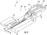
FIG. 3 is a perspective view of a fiber clamp which includes a connector holder and has a plurality of loose optical fibers loaded therein in accordance with embodiments of the present disclosure; -
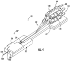
FIG. 4 is a perspective view of a fiber clamp which includes a connector holder and has a fiber optic ribbon loaded therein in accordance with embodiments of the present disclosure; -
FIG. 5 is a perspective view of a fiber clamp which includes a connector holder and has a plurality of loose optical fibers loaded therein in accordance with other embodiments of the present disclosure; -
FIG. 6 is a perspective view of a fiber setting fixture with a fiber clamp secured thereon in accordance with embodiments of the present disclosure; -
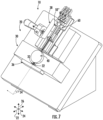
FIG. 7 is a perspective view of a fiber setting fixture with a fiber clamp secured thereon in accordance with other embodiments of the present disclosure; -
FIG. 8 is a perspective view of a portion of a fiber setting fixture, without a fiber clamp secured thereon, in accordance with embodiments of the present disclosure; -
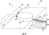
FIG. 9 is a perspective view of a portion of a fiber setting fixture, with a fiber clamp secured thereon and optical fibers inserted into the fiber setting fixture and loaded into the fiber clamp, in accordance with embodiments of the present disclosure; -
FIG. 10 is a perspective view of a portion of a fiber setting fixture, with a cover removed, in accordance with embodiments of the present disclosure; -
FIG. 11 is a top view of a splicer with loaded fiber clamps positioned thereon in accordance with embodiments of the present disclosure; -
FIG. 12 is a spliced fiber optic assembly in accordance with embodiments of the present disclosure; and -
FIG. 13 is a flow chart illustrating a method in accordance with embodiments of the present disclosure. - Reference now will be made in detail to embodiments of the invention, one or more examples of which are illustrated in the drawings. Each example is provided by way of explanation of the invention, not limitation of the invention. In fact, it will be apparent to those skilled in the art that various modifications and variations can be made in the present invention without departing from the scope or spirit of the invention. For instance, features illustrated or described as part of one embodiment can be used with another embodiment to yield a still further embodiment. Thus, it is intended that the present invention covers such modifications and variations as come within the scope of the appended claims and their equivalents.
- Referring now to
FIGS. 1 through 13 , embodiments of optical fibermass splice assemblies 10 and components thereof are provided.Such assemblies 10 may, in some embodiments, be utilized in optical fiber mass splice methods in accordance with the present disclosure. Assemblies 10 and methods in accordance with the present disclosure advantageously provide improve mass splicing of optical fibers which may be particularly useful in fields such as, for example, the medical field and harsh environment field. In particular,assemblies 10 and methods in accordance with the present disclosure advantageously reduce the time, cost, and complexity associate with mass splicing efforts. - Referring now to
FIGS. 1 through 5 , various embodiments of fiber clamps 50 are illustrated. One or more fiber clamps 50, such as in exemplary embodiments first and second fiber clamps 50', 50", may be components of an optical fibermass splice assembly 10 in accordance with the present disclosure. - A
fiber clamp 50 may include aclamp body 52 in which one ormore grooves 54 are defined. In some embodiments, as illustrated inFIG. 1 and4 , asingle groove 54 may be defined which can accommodate anoptical fiber ribbon 100. The optical fiber ribbon may be a standardoptical fiber ribbon 100 having aribbon coating 102 which surrounds a plurality ofoptical fibers 104, or may be an intermittently bonded optical fiber ribbon having a plurality of looseoptical fibers 104 with intermittent bonds between various adjacentoptical fibers 104 throughout the lengths thereof. In other embodiments, as illustrated inFIGS. 2 ,3 , and5 , a plurality ofgrooves 54, which may be aligned in parallel, may be defined. Eachgroove 54 may accommodate a single looseoptical fiber 104. In these embodiments,such clamps 50 may thus accommodate a plurality of looseoptical fibers 104. - When a plurality of
grooves 54 are utilized,grooves 54 may advantageously have a groove pitch and width which corresponds to the groove pitch of thesplicer 80 in which the splicing operations may be performed as discussed herein. For example, in some embodiments, the groove pitch may be nominal 250 micron or 200 micron. In some embodiments, the groove width may be nominal 250 micron, 200 micron, 150 micron, or 100 micron. Further, other suitable widths and pitches may be utilized as desired. In some embodiments, thegroove 54 width is less than thegroove 54 pitch. In these embodiments,grooves 54 are particularly advantageous for maintaining spacing during splicing. - A
fiber clamp 50 may further include acover 56 which may be movably connected to theclamp body 52. For example, in exemplary embodiments as illustrated inFIGS. 1 through 5 , thecover 56 may be rotatably connected to theclamp body 52. Thecover 56 may be movable between an open position, as shown inFIGS. 1 through 3 , which allows loading and/or unloading ofribbons 100 or looseoptical fibers 104 into thegrooves 54, and a closed position, as shown inFIGS. 4 and5 , which clamps theribbons 100 or looseoptical fibers 104 within thefiber clamp 50. - In some embodiments, a
fiber clamp 50 is configured to accommodate a free plurality of optical fibers (whether in ribbon form or loose) which may, for example, be spliced to anoptical fiber pigtail 110, which may for example be a pre-terminated optical fiber pigtail. Embodiments of such first fiber clamps 50' are illustrated inFIGS. 1 and 2 . In other embodiments, afiber clamp 50 is configured to accommodate anoptical fiber pigtail 110. Embodiments of such second fiber clamps 50" are illustrated inFIGS. 3 through 5 . - In some embodiments, a
fiber clamp 50, such as asecond fiber clamp 50", may include additional components to supportconnectors 120 of thepigtails 110 being clamped in the fiber clamps 50. Such support advantageously facilitates control of the position of theconnectors 120 and length of thepigtails 110. Accordingly, a precise distance can be maintained between the splice location and theconnectors 120. This is critical in, for example, medical (e.g. catheters, etc.) and connector housing applications. For example, thefiber clamp 50 may include aconnector holder 60 which is connected to theclamp body 52. In exemplary embodiments, theconnector holder 60 is removable from theclamp body 52.Connector holder 60 may, for example, include anarm 62 and a plurality of connector clips 64. Thearm 62 may be connected to theclamp body 52, and may extend from theclamp body 52. In exemplary embodiments, thearm 62 may be cantilevered from theclamp body 52. The connector clips 64 may be mounted to thearm 62, such as in exemplary embodiments removably mounted to thearm 62. In exemplary embodiments wherein thearm 62 is cantilevered from theclamp body 52, the connector clips 64 may be mounted at a free end of thearm 62 opposite a connected end of thearm 62. Eachconnector clip 64 may hold aconnector 120 which is inserted therein and which is connected to anoptical fiber 104, such as anoptical fiber 104 loaded and/or clamped into thesecond fiber clamp 50". - Referring now to
FIGS. 6 through 10 , optical fibermass splice assemblies 10 may include afiber setting fixture 20. Thefiber setting fixture 20 may advantageously facilitate improved loading ofoptical fiber ribbons 100 and/or looseoptical fibers 104 into fiber clamps 50. An orthogonal coordinate system may be defined for thefiber setting fixture 20. The coordinate system may include, for example, alongitudinal axis 22, alateral axis 24, and atransverse axis 26, each of which may be mutually orthogonal to the other axes. - A
fixture 20 may, for example, include afiber alignment block 30. A plurality offiber grooves 32, which may for example be aligned in parallel, may be defined in thefiber alignment block 30. Eachfiber groove 32 may accommodate a portion of anoptical fiber 104, such as a portion of anoptical fiber 104 from a ribbon 100 (which has, for example, been stripped and/or otherwise processed as necessary) or a portion of a loose optical fiber 100 (which has, for example, been stripped and/or otherwise processed as necessary). Theoptical fibers 104 may be inserted into thefiber setting fixture 30, such as into thefiber grooves 32 of thefiber alignment block 30, to facilitate proper alignment of theoptical fibers 104 and simple, efficient loading of theoptical fibers 104 into fiber clamps 50, such as for splicing purposes. -
Fiber grooves 32 may advantageously have a groove pitch and width which corresponds to the groove pitch of thesplicer 80 in which the splicing operations may be performed as discussed herein. For example, in some embodiments, the groove pitch may be nominal 250 micron or 200 micron. In some embodiments, the groove width may be nominal 250 micron, 200 micron, 150 micron, or 100 micron. Further, other suitable widths and pitches may be utilized as desired. In some embodiments, thegroove 32 width is less than thegroove 32 pitch. In these embodiments,grooves 32 are particularly advantageous for maintaining spacing during splicing. - In exemplary embodiments, the
fiber grooves 32 may be oriented and extend (such as lengthwise) at anangle 34 to a plane defined by thelongitudinal axis 22 and thelateral axis 24. Theangle 34 may, for example, be in the range between 15 degrees and 75 degrees, such as between 25 degrees and 65 degrees, such as between 35 degrees and 55 degrees, such as between 40 degrees and 50 degrees. The angle of thefiber grooves 32 may advantageously facilitate proper loading of theoptical fibers 104 therein. -
Fiber setting fixture 20 may further include abackstop 36 which may, for example, be disposed proximate theblock 30 andfiber grooves 32. For example, backstop 36 may be positioned at a distal end of thefiber grooves 32. When anoptical fiber 104 is inserted into afiber groove 32, theoptical fiber 104 may traverse through the length of thefiber groove 32 until theoptical fiber 104 reaches the distal end of thefiber groove 32 and encounters thebackstop 36. At this point, theoptical fiber 104 may abut against thebackstop 36, such that further lengthwise traversal of theoptical fiber 104 is prevented. Accordingly, eachoptical fiber 104 of a plurality ofoptical fibers 104 inserted into thefiber grooves 32 is inserted to a uniform length/distance, thus ensuring precise and accurate alignment and loading into aclamp 50, such as for splicing purposes. - The
fiber setting fixture 20 may further include afiber clamp mount 38. Eachfiber clamp 50, which may for example be a component of anassembly 10, may be removably securable to the fiber clamp mount 38 to facilitate loading ofoptical fibers 104 therein. Thefiber clamp mount 38 may further be movable relative to thefiber alignment block 30, such as along at least one axis. Such movement may facilitate alignment of the one ormore grooves 54 with the plurality offiber grooves 32. Accordingly, after such alignment,optical fibers 104 may, for example, be first inserted into thefiber grooves 32 and then loaded into the one ormore grooves 54. Accordingly, efficient, precise, and accurate loading into aclamp 50 is facilitated. - In exemplary embodiments, mount 38 may be movable along the
lateral axis 24. Additionally or alternatively, mount 38 may be movable along thelongitudinal axis 22 and/or thetransverse axis 24. - The
fiber setting fixture 20 may further include acover 40.Cover 40 may removably enclose at least a portion of the plurality offiber grooves 32, such thatoptical fibers 104 being inserted into thefiber grooves 32 are inserted between thecover 40 and theblock 30.Cover 40 may, for example, be removably connectable to theblock 30 or movably connected to theblock 30. When theoptical fibers 104 are being inserted into thefiber grooves 32, thecover 40 may be disposed on thefiber alignment block 30 such that thefiber grooves 32 are at least partially enclosed. After theoptical fibers 104 are secured in aclamp 50, thecover 40 may then be removable from thefiber grooves 32, such as via removal from thefiber alignment block 30 or movement from a closed position to an open position, to allow simple and efficient removal of theoptical fibers 104 from thefiber grooves 32. - In exemplary embodiments, the
cover 40 may be a magnet. Alternatively, thecover 40 may be a hinged block or other suitable apparatus for selectively enclosing at least portions of thefiber grooves 32. - As discussed, and referring again to
FIGS. 1 through 13 , the present disclosure is further directed to optical fiber mass splice methods. Amethod 200 in accordance with the present disclosure may, for example, include thestep 210 of securing afiber clamp 50, such as a first fiber clamp 50' as illustrated inFIG. 6 or asecond fiber clamp 50" as illustrated inFIG. 7 , to afiber setting fixture 20. For example, thefiber clamp 50 may be secured to afiber clamp mount 38.FIG. 8 illustrates afixture 20 prior to, for example, securing of afiber clamp 50 to amount 38 of thefixture 20.FIGS. 9 and10 illustrate afiber clamp 50 mounted to amount 38 of thefixture 20. - A
method 200 may further include thestep 215 of aligning the one ormore grooves 54 of thefiber clamp 50 with the plurality offiber grooves 32 of thefiber setting fixture 20. Such alignment is illustrated, for example, by arrows inFIGS. 6 and7 . - A
method 200 may further include thestep 220 of inserting a plurality of optical fibers 104 (whether in loose form or ribbon form, as discussed herein) into thefiber setting fixture 20 such that each of the plurality ofoptical fibers 104 is disposed in one of the plurality offiber grooves 32 and contacts thebackstop 36. Such insertion is illustrated, for example, inFIG. 9 . For example, the plurality offiber grooves 32 may each extend along a lengthwise direction (and may advantageously be parallel), and the plurality ofoptical fibers 104 may be inserted along the lengthwise direction until each of the plurality ofoptical fibers 104 contacts thebackstop 36. - A
method 200 may further include thestep 225 of loading each of the plurality ofoptical fibers 104 into thefiber clamp 50.Such loading step 225 may, in exemplary embodiments, occur after the insertingstep 220. Theclamp 50 may, for example, be in an open position for such loading. Loading may include, for example, inserting the optical fibers 104 (such as of aribbon 100, or loose optical fibers 104) into the one ormore grooves 54.FIG. 9 illustratesoptical fibers 104 loaded into anopen fiber clamp 50. - A
method 200 may further include thestep 230 of clamping the plurality ofoptical fibers 104 into thefiber clamp 50.Such clamping step 230 may, in exemplary embodiments, occur after theloading step 225. Such clamping may include moving theclamp 50 from an open position to a closed position. When clamped, theoptical fibers 104 may be secured in position in thegrooves 54.FIG. 10 illustratesoptical fibers 104 clamped into afiber clamp 50. - A
method 200 may further include thestep 235 of removing thecover 40 from the plurality offiber grooves 32. Such removingstep 235 may, for example, occur after the clampingstep 230.FIG. 10 illustrates anassembly 10 with thecover 40 removed from thefiber grooves 32. - After the plurality of
optical fibers 104 are secured in aclamp 50, theclamp 50 may be removed from thefixture 20 for splicing and/or other processing. For example, amethod 200 may include thestep 240 of removing the loaded and clampedfiber clamp 50 from thefiber clamp mount 28. - After the
removal step 240, various steps as discussed herein may be repeated using another plurality ofoptical fibers 104 and anotherclamp 50. For example, one or more ofsteps 210 through 240 may be repeated. In some embodiments, such steps may be performed for a first plurality of optical fibers 104' and with a first fiber clamp 50', and such steps may also be performed for a second plurality ofoptical fibers 104" and with asecond fiber clamp 50". The first plurality of optical fibers 104' may be a free plurality of optical fibers, and the second plurality ofoptical fibers 104" may be anoptical fiber pigtail 110. - In some embodiments,
method 200 may further include the step of cleaving theoptical fibers 104, such as the first plurality of optical fibers 104' and second plurality ofoptical fibers 104". In exemplary embodiments, such step may occur afterremoval step 240. - In some embodiments,
method 200 may further include thestep 250 of transporting a loaded and clampedfiber clamp 50 from thefiber setting fixture 20 to asplicer 80. Such step may, for example, occur for a loaded and clamped first fiber clamp 50' and for a loaded and clampedsecond fiber clamp 50". Such step may, for example, occur after cleaving of theoptical fibers 104 as discussed above. A transported, loaded, and clamped first andsecond fiber clamp 50', 50" in asplicer 80 is shown inFIG. 11 . - Once transported, the
optical fibers 104 clamped in the fiber clamps 50 may, for example, be spliced together and/or otherwise processed. For example, in some embodiments, first optical fibers 104' and secondoptical fibers 104" may be spliced together in thesplicer 80. Further, after splicing, a splice protector sleeve 82 (which may, for example, be preloaded on the first optical fibers 104' or secondoptical fibers 104") may be provided on the splice which results from splicing of the first optical fibers 104' and secondoptical fibers 104" together. Thesplice protector sleeve 82 for example be formed from a heat shrink material. Thesplice protector sleeve 82 may be heated onto the spliced together first optical fiber 104' and secondoptical fiber 104" to protect the splice.FIG. 12 illustrates a spliced fiber optic assembly which includes spliced together first optical fibers 104' and secondoptical fibers 104" and further includes asplice protector sleeve 82 heated thereon. - This written description uses examples to disclose the invention, including the best mode, and also to enable any person skilled in the art to practice the invention, including making and using any devices or systems and performing any incorporated methods. The patentable scope of the invention is defined by the claims, and may include other examples that occur to those skilled in the art. Such other examples are intended to be within the scope of the claims if they include structural elements that do not differ from the literal language of the claims, or if they include equivalent structural elements with insubstantial differences from the literal languages of the claims.
Claims (15)
- A fiber setting fixture (20) for optical fiber mass splicing, comprising:a fiber alignment block (30), wherein a plurality of fiber grooves (32) is defined in the fiber alignment block (30);a fiber clamp mount (38) movable relative to the fiber alignment block (30) along at least one axis; anda fiber clamp (50) removably securable to the fiber clamp mount (38), the fiber clamp (50) comprising a clamp body (52) and at least one groove (54) defined in the clamp body (52), wherein the at least one groove (54) defined in the clamp body (52) maintains a fiber pitch equal to the plurality of fiber grooves (32) in the fiber alignment block (30).
- The fiber setting fixture (20) of claim 1, wherein a longitudinal axis, lateral axis, and transverse axis are defined by the fiber setting fixture (20), and wherein the plurality of fiber grooves (32) extend at an angle to a plane defined by the longitudinal axis and lateral axis.
- The fiber setting fixture (20) of claim 2, wherein the angle is between about 15 degrees and about 75 degrees.
- The fiber setting fixture (20) of claim 1, wherein the plurality of fiber grooves (32) is configured to receive a respective fiber.
- The fiber setting fixture (20) of claim 1, comprising a cover (56) removably enclosing at least a portion of the plurality of fiber grooves (32).
- The fiber setting fixture (20) of clam 5, wherein the cover (56) is a magnet.
- The fiber setting fixture (20) of claim 1, wherein the fiber clamp (50) comprises a connector holder (60) comprising an arm (62) extending from the clamp body (52) and a plurality of connector clips (64) mounted to the arm (62).
- The fiber setting fixture (20) of claim 7, wherein the plurality of connector clips (64) are removably mounted to the arm (62).
- The fiber setting fixture (20) of claim 7, wherein the arm (62) is cantilevered from the clamp body (52) and the plurality of connector clips (64) are mounted at a free end of the arm (62).
- The fiber setting fixture (20) of claim 7, wherein the plurality of connector clips (64) is configured to receive a respective connector at each connector clip.
- The fiber setting fixture (20) of claim 1, comprising a splicer, wherein the fiber alignment block (30) and the fiber clamp mount (38) is positioned at the splicer.
- An optical fiber mass splice method, comprising:securing a fiber clamp (50) to a fiber setting fixture (20), the fiber setting fixture (20) comprising a fiber alignment block (30) and a backstop (36), wherein a plurality of fiber grooves (32) is defined in the fiber alignment block (30), and wherein the plurality of fiber grooves (32) of the fiber setting fixture (30) each extend along a lengthwise direction;inserting a plurality of optical fibers (104) into the fiber setting fixture (20) such that each of the plurality of optical fibers (104) is disposed in one of the plurality of fiber grooves (32) and contacts the backstop (26), wherein the plurality of optical fibers (104) is inserted along the lengthwise direction until each of the plurality of optical fibers contacts the backstop (36);loading, after the inserting step, each of the plurality of optical fibers (104) into the fiber clamp (50); andclamping the plurality of optical fibers (104) in the fiber clamp (50).
- The method of claim 12, wherein the fiber clamp (50) comprises at least one groove (54), and further comprising aligning the at least one groove (54) of the fiber clamp (50) with the plurality of fiber grooves (32) of the alignment block (30).
- The method of claim 13, comprising maintaining a fiber pitch at the plurality of fiber grooves (32) equal to a fiber pitch at the at least one groove (54) of the clamp body (50).
- The method of claim 12, wherein clamping the plurality of optical fibers (104) in the fiber clamp (50) comprises moving the fiber clamp (50) from an open position to a closed position to secure the plurality of optical fibers (104) in the plurality of fiber grooves.
Applications Claiming Priority (3)
| Application Number | Priority Date | Filing Date | Title |
|---|---|---|---|
| US201862721896P | 2018-08-23 | 2018-08-23 | |
| EP19762028.9A EP3841413B1 (en) | 2018-08-23 | 2019-08-16 | Optical fiber mass splice methods and assemblies |
| PCT/US2019/046729 WO2020041101A1 (en) | 2018-08-23 | 2019-08-16 | Optical fiber mass splice methods and assemblies |
Related Parent Applications (2)
| Application Number | Title | Priority Date | Filing Date |
|---|---|---|---|
| EP19762028.9A Division-Into EP3841413B1 (en) | 2018-08-23 | 2019-08-16 | Optical fiber mass splice methods and assemblies |
| EP19762028.9A Division EP3841413B1 (en) | 2018-08-23 | 2019-08-16 | Optical fiber mass splice methods and assemblies |
Publications (1)
| Publication Number | Publication Date |
|---|---|
| EP4163686A1 true EP4163686A1 (en) | 2023-04-12 |
Family
ID=67809690
Family Applications (2)
| Application Number | Title | Priority Date | Filing Date |
|---|---|---|---|
| EP22202816.9A Pending EP4163686A1 (en) | 2018-08-23 | 2019-08-16 | Optical fiber mass splice methods and assemblies |
| EP19762028.9A Active EP3841413B1 (en) | 2018-08-23 | 2019-08-16 | Optical fiber mass splice methods and assemblies |
Family Applications After (1)
| Application Number | Title | Priority Date | Filing Date |
|---|---|---|---|
| EP19762028.9A Active EP3841413B1 (en) | 2018-08-23 | 2019-08-16 | Optical fiber mass splice methods and assemblies |
Country Status (3)
| Country | Link |
|---|---|
| US (2) | US11614586B2 (en) |
| EP (2) | EP4163686A1 (en) |
| WO (1) | WO2020041101A1 (en) |
Families Citing this family (4)
| Publication number | Priority date | Publication date | Assignee | Title |
|---|---|---|---|---|
| US11614586B2 (en) * | 2018-08-23 | 2023-03-28 | Afl Telecommunications Llc | Optical fiber mass splice methods and assemblies |
| CA3151278A1 (en) * | 2019-09-18 | 2021-03-25 | Jason Daniel ANDREWS | Ribbon splicing tools and methods |
| MX2023008697A (en) | 2021-01-27 | 2023-08-01 | Afl Telecommunications Llc | HOUSING AND CLIP FOR FIBER OPTICS. |
| CN114986074B (en) * | 2022-08-03 | 2022-10-21 | 山西省安装集团股份有限公司 | Boiler pipeline is with anchor clamps of keeping to needs of job |
Citations (3)
| Publication number | Priority date | Publication date | Assignee | Title |
|---|---|---|---|---|
| JPS62254108A (en) * | 1986-04-28 | 1987-11-05 | Nippon Telegr & Teleph Corp <Ntt> | Core fusion splicer for multi-paired optical fiber tape |
| US5813902A (en) * | 1997-04-14 | 1998-09-29 | Minnesota Mining And Manufacturing Company | Optical fiber end-face preparation and connector assembly |
| EP2700989A1 (en) * | 2012-03-29 | 2014-02-26 | Fujikura Ltd. | Optical fiber fusion splicer |
Family Cites Families (10)
| Publication number | Priority date | Publication date | Assignee | Title |
|---|---|---|---|---|
| FR2348168A1 (en) * | 1976-04-14 | 1977-11-10 | Cables De Lyon Geoffroy Delore | BUTT-TO-BUT OPTIC FIBER WELDING DEVICE |
| FR2445972A1 (en) * | 1979-01-03 | 1980-08-01 | Lyonnaise Transmiss Optiques | DEVICE FOR WELDING MULTIPLE OPTICAL FIBERS END-TO-END THROUGH TABLECLOTHS AND WELDING METHOD USING THE SAME |
| JPS61205904A (en) | 1985-03-08 | 1986-09-12 | Sumitomo Electric Ind Ltd | fiber optic cutter |
| EP0216307A3 (en) * | 1985-09-26 | 1989-08-02 | Siemens Aktiengesellschaft | Mechanical fixture for positioning two optical-fibre ends |
| DE3613345A1 (en) * | 1986-04-19 | 1987-10-22 | Philips Patentverwaltung | DEVICE FOR PAIRING THE ENDS OF TWO GROUPS OF FIBER-SHAPED FIBER-WAVE GUIDES IN PAIRS |
| JPH0670684B2 (en) | 1986-12-16 | 1994-09-07 | 日本電信電話株式会社 | Optical fiber cutter |
| JPH07218753A (en) * | 1994-02-04 | 1995-08-18 | Fujikura Ltd | Optical fiber fusion splicing method and fusion splicer |
| JP2003329873A (en) * | 2001-12-27 | 2003-11-19 | Fujikura Ltd | Optical fiber gripper with positioning mechanism, optical fiber adapter, and optical fiber processing device |
| CN103477259B (en) * | 2011-04-15 | 2016-02-24 | Sei光学前沿株式会社 | Structure of fiber_optic |
| US11614586B2 (en) * | 2018-08-23 | 2023-03-28 | Afl Telecommunications Llc | Optical fiber mass splice methods and assemblies |
-
2019
- 2019-08-16 US US17/265,748 patent/US11614586B2/en active Active
- 2019-08-16 EP EP22202816.9A patent/EP4163686A1/en active Pending
- 2019-08-16 EP EP19762028.9A patent/EP3841413B1/en active Active
- 2019-08-16 WO PCT/US2019/046729 patent/WO2020041101A1/en not_active Ceased
-
2022
- 2022-11-14 US US17/986,071 patent/US12078844B2/en active Active
Patent Citations (3)
| Publication number | Priority date | Publication date | Assignee | Title |
|---|---|---|---|---|
| JPS62254108A (en) * | 1986-04-28 | 1987-11-05 | Nippon Telegr & Teleph Corp <Ntt> | Core fusion splicer for multi-paired optical fiber tape |
| US5813902A (en) * | 1997-04-14 | 1998-09-29 | Minnesota Mining And Manufacturing Company | Optical fiber end-face preparation and connector assembly |
| EP2700989A1 (en) * | 2012-03-29 | 2014-02-26 | Fujikura Ltd. | Optical fiber fusion splicer |
Also Published As
| Publication number | Publication date |
|---|---|
| EP3841413B1 (en) | 2022-11-23 |
| US20230076590A1 (en) | 2023-03-09 |
| EP3841413A1 (en) | 2021-06-30 |
| US11614586B2 (en) | 2023-03-28 |
| WO2020041101A1 (en) | 2020-02-27 |
| US20210302655A1 (en) | 2021-09-30 |
| US12078844B2 (en) | 2024-09-03 |
Similar Documents
| Publication | Publication Date | Title |
|---|---|---|
| US12078844B2 (en) | Optical fiber mass splice methods and assemblies | |
| CA2073481C (en) | Closure for optical fiber connective arrangements | |
| US8885998B2 (en) | Splice enclosure arrangement for fiber optic cables | |
| US4812010A (en) | Apparatus for arranging a plurality of coated optical fibers and collective fusion splicing method using the apparatus | |
| US8155490B2 (en) | Fiber optic cable furcation assemblies and methods | |
| CA2068086C (en) | Optical fiber array splicing device | |
| CN113740973B (en) | Flexible optical fiber circuit and manufacturing method thereof | |
| US20050213897A1 (en) | Field-installable fusion spliced fiber optic connector kits and methods therefor | |
| US9459408B2 (en) | Cable splicing fixture | |
| US20150003790A1 (en) | Field mountable duplex optical fiber connector with mechanical splice elements | |
| EP0429163A1 (en) | Optical fiber splicing device | |
| EP0031451B1 (en) | Method for connecting optical fibers and optical fiber connector | |
| US11906782B2 (en) | Terminating a cable assembly with connectorized pigtails | |
| EP0524079A1 (en) | Fiber optic splice connection | |
| US20100301502A1 (en) | Method of directly molding ferrule on fiber optic cable | |
| CN1555504A (en) | Methods for Tapping Fiber | |
| EP1312955B1 (en) | Process for coupling optical fibres | |
| EP1224494A1 (en) | Method and apparatus for recoating a fiber optic splice | |
| EP1018658A2 (en) | Multifiber alignment adapter and associated fiber optic connector subassemmbly | |
| WO2004008214A1 (en) | Component for connecting optical fibers, optical fiber connection structure, and optical fiber connecting method | |
| JP3950781B2 (en) | Optical fiber connection method and connection structure | |
| US12044885B2 (en) | Jig for fusion splicer and heating method | |
| JP3710538B2 (en) | Multi-fiber single-fiber conversion optical fiber with optical fiber connector | |
| JP4292260B2 (en) | Optical fiber connection device | |
| JPH09197168A (en) | Optical fiber for multi-fiber / single fiber conversion with optical fiber connector |
Legal Events
| Date | Code | Title | Description |
|---|---|---|---|
| PUAI | Public reference made under article 153(3) epc to a published international application that has entered the european phase |
Free format text: ORIGINAL CODE: 0009012 |
|
| STAA | Information on the status of an ep patent application or granted ep patent |
Free format text: STATUS: THE APPLICATION HAS BEEN PUBLISHED |
|
| AC | Divisional application: reference to earlier application |
Ref document number: 3841413 Country of ref document: EP Kind code of ref document: P |
|
| AK | Designated contracting states |
Kind code of ref document: A1 Designated state(s): AL AT BE BG CH CY CZ DE DK EE ES FI FR GB GR HR HU IE IS IT LI LT LU LV MC MK MT NL NO PL PT RO RS SE SI SK SM TR |
|
| STAA | Information on the status of an ep patent application or granted ep patent |
Free format text: STATUS: REQUEST FOR EXAMINATION WAS MADE |
|
| 17P | Request for examination filed |
Effective date: 20231006 |
|
| RBV | Designated contracting states (corrected) |
Designated state(s): AL AT BE BG CH CY CZ DE DK EE ES FI FR GB GR HR HU IE IS IT LI LT LU LV MC MK MT NL NO PL PT RO RS SE SI SK SM TR |
|
| STAA | Information on the status of an ep patent application or granted ep patent |
Free format text: STATUS: EXAMINATION IS IN PROGRESS |
|
| 17Q | First examination report despatched |
Effective date: 20240620 |
|
| 17Q | First examination report despatched |
Effective date: 20240627 |
|
| GRAP | Despatch of communication of intention to grant a patent |
Free format text: ORIGINAL CODE: EPIDOSNIGR1 |
|
| STAA | Information on the status of an ep patent application or granted ep patent |
Free format text: STATUS: GRANT OF PATENT IS INTENDED |
|
| INTG | Intention to grant announced |
Effective date: 20260323 |
|
| RIN1 | Information on inventor provided before grant (corrected) |
Inventor name: LICHOULAS, TED Inventor name: DONALDSON, CHRIS Inventor name: BRANKS, BOBBY |