EP4163622B1 - Non-modulated infrared sensor for hand-held halogen leak detector and its quantitative detection method - Google Patents
Non-modulated infrared sensor for hand-held halogen leak detector and its quantitative detection method Download PDFInfo
- Publication number
- EP4163622B1 EP4163622B1 EP22200876.5A EP22200876A EP4163622B1 EP 4163622 B1 EP4163622 B1 EP 4163622B1 EP 22200876 A EP22200876 A EP 22200876A EP 4163622 B1 EP4163622 B1 EP 4163622B1
- Authority
- EP
- European Patent Office
- Prior art keywords
- infrared
- gas
- light source
- leak detector
- handheld
- Prior art date
- Legal status (The legal status is an assumption and is not a legal conclusion. Google has not performed a legal analysis and makes no representation as to the accuracy of the status listed.)
- Active
Links
Images


Classifications
-
- G—PHYSICS
- G01—MEASURING; TESTING
- G01N—INVESTIGATING OR ANALYSING MATERIALS BY DETERMINING THEIR CHEMICAL OR PHYSICAL PROPERTIES
- G01N21/00—Investigating or analysing materials by the use of optical means, i.e. using sub-millimetre waves, infrared, visible or ultraviolet light
- G01N21/17—Systems in which incident light is modified in accordance with the properties of the material investigated
- G01N21/25—Colour; Spectral properties, i.e. comparison of effect of material on the light at two or more different wavelengths or wavelength bands
- G01N21/31—Investigating relative effect of material at wavelengths characteristic of specific elements or molecules, e.g. atomic absorption spectrometry
- G01N21/35—Investigating relative effect of material at wavelengths characteristic of specific elements or molecules, e.g. atomic absorption spectrometry using infrared light
- G01N21/3504—Investigating relative effect of material at wavelengths characteristic of specific elements or molecules, e.g. atomic absorption spectrometry using infrared light for analysing gases, e.g. multi-gas analysis
-
- G—PHYSICS
- G01—MEASURING; TESTING
- G01M—TESTING STATIC OR DYNAMIC BALANCE OF MACHINES OR STRUCTURES; TESTING OF STRUCTURES OR APPARATUS, NOT OTHERWISE PROVIDED FOR
- G01M3/00—Investigating fluid-tightness of structures
- G01M3/02—Investigating fluid-tightness of structures by using fluid or vacuum
- G01M3/04—Investigating fluid-tightness of structures by using fluid or vacuum by detecting the presence of fluid at the leakage point
-
- G—PHYSICS
- G01—MEASURING; TESTING
- G01N—INVESTIGATING OR ANALYSING MATERIALS BY DETERMINING THEIR CHEMICAL OR PHYSICAL PROPERTIES
- G01N2201/00—Features of devices classified in G01N21/00
- G01N2201/02—Mechanical
- G01N2201/022—Casings
- G01N2201/0221—Portable; cableless; compact; hand-held
Definitions
- the present invention relates to a non-modulated infrared sensor for a handheld halogen leak detector and a quantitative detection method thereof.
- the sensor technologies used in handheld (portable) leak detector are mostly heating diode and negative corona discharge technologies, but there are often a series of problems: the heating-diode sensor has the problems of short life and false alarm; the corona sensor has problems such as poor stability, low accuracy, short life, and inability to quantitatively detect gas leakage.
- US7022993B1 describes a leak detector using a non-modulated infrared sensor for detecting rapid increases in a concentration of a selected gas, e.g., a refrigerant.
- US2008/277586 A1 describes a photo-acoustic infrared gas monitor configured to quantify gas concentrations at a particular location.
- the gas monitor comprises a pulsed infrared source, a sample chamber, and a microphone.
- a gas inlet of the sample chamber is connected to a two-way valve, wherein one intake of the valve may be connected to a source of calibration gas known to not contain the target gas, such as external environmental air, and the other intake may be connected to the gas to be monitored.
- the present invention provides a non-modulated infrared sensor for a handheld halogen leak detector and a quantitative detection method thereof.
- the sensor has a simple structure and can not only locate the leak point quickly, has no blind area and will not miss leak point, but can also detect the amount of gas leakage and obtain more accurate detection results.
- a non-modulated infrared sensor for a handheld halogen leak detector comprising an infrared transmitter, an optical filter, an infrared absorption cell, an infrared receiver, a solenoid valve, an amplification filter module, an analog-digital conversion module, and a single-chip microcomputer control system; wherein the infrared transmitter and the optical filter are sequentially installed at one end of the infrared absorption cell, and the infrared receiver is installed at the other end of the infrared absorption cell; the infrared absorption cell is composed of a light source chamber, a gas chamber channel and an infrared-receiver chamber that are sealingly connected in sequence, the light source chamber and the infrared-receiver chamber are respectively provided with a gas inlet and a gas outlet, and the solenoid valve is configured to switch a gas path so that the gas inlet is communicated either with a target gas or a background
- a quantitative detection method based on the non-modulated infrared sensor for a handheld halogen leak detector comprising the following steps:
- the present invention provides a non-modulated infrared sensor for a handheld halogen leak detector and a quantitative detection method thereof, wherein the sensor is essentially a single-channel quantitative non-dispersive infrared sensor with simple and innovative structure, which can find the leak point easily and quickly.
- the infrared receiver detects the change of the light signal in real time as the light source is always on. If the target gas blocks and absorbs the light signal of a specific band, the infrared receiver responds immediately and quickly locates the leak point, it has no blind area and will not miss leak point.
- the utility model adopts a solenoid valve for gas switching to compare the difference between the target gas and the background gas, so as to detect the gas leakage amount.
- the method can remove the influence of the background interference gas, so that the detection result is more accurate.
- the gas outlet is also connected with an air pump which is connected with the single-chip microcomputer control system, so it is easy to match collection requirement of the infrared receiver analysis requirement of single chip microcomputer system and switching requirement of solenoid valve, to intelligently control the exhaust flow and maximize the synergistic effect.
- a further optimization and improvement is that a second resistor R2 is also connected between the source and the gate of the MOS transistor Q1, and the gate of the MOS transistor Q1 is connected to the control port of the single-chip microcomputer control system through a third resistor R3 to control the voltage difference between the source and the gate of the MOS transistor Q1 to turn on or off the MOS transistor Q1, where the second resistor R2 and the third resistor R3 belong to the pull-up resistors for avoiding the leakage of electricity of the MOS transistor Q1 when the voltage difference between the source and the gate is too high at the moment of power on; filter capacitors are also provided between the output end of the constant voltage power supply circuit and the source of the MOS transistor Q1, and the number of the filter capacitors can be several, in this example, two filter capacitors are set, namely, the filter capacitor C1 and the filter capacitor C2.
- the MOS transistor Q1 When powered on, the MOS transistor Q1 is turned off, and the infrared light source U1 is connected to the power resistor R1 to achieve preheating, after a set interval, the MOS transistor Q1 is turned on, and the infrared light source U1 reaches the specified power step by step, which plays a protective role.
- the conventional detection method is the modulation method.
- the modulation has a steady-state process of the light source.
- the modulated light source has an intermittent on and off process, and there is a signal when it is on, forming a peak or valley on the graph, and there is no signal when it is off, corresponding to the transition section between the peaks and valleys on the graph.
- the signal change can only be formed just when the light source is on, but when there is a slight deviation, i.e., when the signal change is small or there is no signal change (see Figures 6a , 6c ), it is easy to miss the leak point, which is not conducive to the realization of quantitative, accurate and real-time acquisition.
- the infrared light source is powered by a lithium battery alone, which is conducive to maintaining a better, stable and always-on effect.
Landscapes
- Physics & Mathematics (AREA)
- Spectroscopy & Molecular Physics (AREA)
- General Physics & Mathematics (AREA)
- Biochemistry (AREA)
- Chemical & Material Sciences (AREA)
- Analytical Chemistry (AREA)
- Life Sciences & Earth Sciences (AREA)
- General Health & Medical Sciences (AREA)
- Health & Medical Sciences (AREA)
- Immunology (AREA)
- Pathology (AREA)
- Investigating Or Analysing Materials By Optical Means (AREA)
- Examining Or Testing Airtightness (AREA)
Description
- The present invention relates to a non-modulated infrared sensor for a handheld halogen leak detector and a quantitative detection method thereof.
- At present, the sensor technologies used in handheld (portable) leak detector are mostly heating diode and negative corona discharge technologies, but there are often a series of problems: the heating-diode sensor has the problems of short life and false alarm; the corona sensor has problems such as poor stability, low accuracy, short life, and inability to quantitatively detect gas leakage.
- It is well known that infrared technology has existed for many years, but it has not been applied to handheld fixed-point detection of leakage of halogen gas for refrigeration, for the following reasons:
- Firstly, the modulated light source of the existing infrared sensor passes through the gas to be detected, and the analyzed gas contains very little refrigerant gas, the absorption of light energy is very small, and the change of the receiver is extremely small, resulting in that a signal-to-noise ratio in the system is not obvious, and the response speed of detection cannot meet the demand;
- Secondly, the chopper of the existing infrared sensor consumes a large amount of energy, also increases the complexity of the instrument and reduces the reliability of the instrument. At the same time, chopping also occurs with frequency, so there is a certain blank of time, thus it is also easy to miss the leak point.
-
US7022993B1 describes a leak detector using a non-modulated infrared sensor for detecting rapid increases in a concentration of a selected gas, e.g., a refrigerant. -
US2008/277586 A1 describes a photo-acoustic infrared gas monitor configured to quantify gas concentrations at a particular location. The gas monitor comprises a pulsed infrared source, a sample chamber, and a microphone. A gas inlet of the sample chamber is connected to a two-way valve, wherein one intake of the valve may be connected to a source of calibration gas known to not contain the target gas, such as external environmental air, and the other intake may be connected to the gas to be monitored. - In order to overcome the above-mentioned deficiencies of the prior art, the present invention provides a non-modulated infrared sensor for a handheld halogen leak detector and a quantitative detection method thereof. The sensor has a simple structure and can not only locate the leak point quickly, has no blind area and will not miss leak point, but can also detect the amount of gas leakage and obtain more accurate detection results.
- The technical solution adopted by the present invention to solve the technical problem is:
A non-modulated infrared sensor for a handheld halogen leak detector, comprising an infrared transmitter, an optical filter, an infrared absorption cell, an infrared receiver, a solenoid valve, an amplification filter module, an analog-digital conversion module, and a single-chip microcomputer control system; wherein the infrared transmitter and the optical filter are sequentially installed at one end of the infrared absorption cell, and the infrared receiver is installed at the other end of the infrared absorption cell; the infrared absorption cell is composed of a light source chamber, a gas chamber channel and an infrared-receiver chamber that are sealingly connected in sequence, the light source chamber and the infrared-receiver chamber are respectively provided with a gas inlet and a gas outlet, and the solenoid valve is configured to switch a gas path so that the gas inlet is communicated either with a target gas or a background gas through the solenoid valve; the infrared receiver is a single-channel detector; an infrared light source of the infrared transmitter is powered by a constant voltage power supply circuit; and the infrared receiver is connected to the single-chip microcomputer control system through the amplification filter module and the analog-digital conversion module, and the single-chip microcomputer control system is in control connection with the solenoid valve, and the single-chip microcomputer control system is configured to determine halogen leakage concentration based on signals acquired by the infrared receiver when the gas inlet is communicated with the target gas and signals acquired by the infrared receiver when the gas inlet is communicated with the background gas. - A quantitative detection method based on the non-modulated infrared sensor for a handheld halogen leak detector, comprising the following steps:
- 1) keeping the infrared light source always on to form a light source signal in the infrared absorption cell;
- 2) firstly introducing target gas via the gas inlet by switching the solenoid valve in the infrared absorption cell, and collecting 32 groups of data of the target gas in sequence to form an acquisition target signal; then introducing background gas through the gas inlet at an interval, and collecting 32 groups of data of the background gas in sequence to form an acquisition comparison signal;
- 3) wherein the acquisition of the target signal and the comparison signal in step 2) is performed by the infrared receiver with delay after the switching action of the solenoid valve, and the peak-to-peak values of the target signal and the comparison signal are collected;
- 4) wherein the target signal and comparison signal collected in step 3) are sequentially filtered and amplified through band-pass filtering and low-pass filtering, and then input into the single-chip microcomputer control system after analog conversion, so as to judge halogen leakage concentration by comparing the difference between the target signal and the comparison signal based on Fourier algorithm and median sliding filtering algorithm.
- Compared with the prior art, the present invention provides a non-modulated infrared sensor for a handheld halogen leak detector and a quantitative detection method thereof, wherein the sensor is essentially a single-channel quantitative non-dispersive infrared sensor with simple and innovative structure, which can find the leak point easily and quickly. The infrared receiver detects the change of the light signal in real time as the light source is always on. If the target gas blocks and absorbs the light signal of a specific band, the infrared receiver responds immediately and quickly locates the leak point, it has no blind area and will not miss leak point. At the same time, the utility model adopts a solenoid valve for gas switching to compare the difference between the target gas and the background gas, so as to detect the gas leakage amount. Thus the method can remove the influence of the background interference gas, so that the detection result is more accurate.
- The present invention will be further described below in conjunction with the accompanying drawings and examples.
-
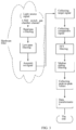
Fig. 1 is a structural block diagram of an example of the present invention. -
Fig. 2 is a circuit diagram of a soft-start protection circuit in an example of the present invention. -
Fig. 3 is a schematic flowchart of a detection method according to an example of the present invention. -
Fig. 4 is a flowchart of switching control of a solenoid valve in a detection method according to an example of the present invention. -
Fig. 5a andFig. 5b are signal curves of concentration of leaked gas obtained according to an example of the - present invention, wherein
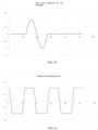
Fig. 5a is the signal curve without detection when the light source is always on, andFig. 5b is the signal curve with leak point being detected when the light source is always on. -
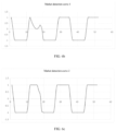
Figs. 6a ,6b and 6c are the signal curves of concentration of leaked gas of the prior art, whereinFig. 6a is the signal curve without detection under the modulation/chopping light source, andFig. 6b is signal curve for detection when the brightness of the modulation/chopping light source is max, and -
Fig. 6c is the signal curve for detection when the brightness of the modulation/chopping light source becomes weak. - In order to make the purposes, technical solutions and advantages of the examples of the present invention more clear, hereunder the technical solutions in the examples of the present invention will be clearly and completely described below with reference to the accompanying drawings of the examples of the present invention. Obviously, the described examples are only some examples of the present invention, and not all the examples. The scope of the invention is defined by the appended claims.
- Referring to
Fig. 1 , in a preferred example of the present invention, a non-modulated infrared sensor for a handheld halogen leak detector is provided, which comprises an infrared transmitter, an optical filter, an infrared absorption cell and an infrared receiver, the infrared transmitter and the optical filter being sequentially installed at one end of the infrared absorption cell, and the infrared receiver being installed at the other end of the infrared absorption cell; the infrared absorption cell is composed of a light source chamber, a gas chamber channel and an infrared-receiver chamber that are sealingly connected in sequence, the light source chamber and the infrared-receiver chamber are respectively provided with a gas inlet and a gas outlet, and the gas inlet is communicated with the target gas or the background gas through a solenoid valve; the infrared receiver is connected to a single-chip microcomputer control system through an amplification filter module and an analog-digital conversion module, and the single-chip microcomputer control system is in control connection with the solenoid valve; an infrared light source of the infrared transmitter passes through a constant voltage power supply circuit. In this example, the infrared receiver is a single-channel detector, which not only has a simpler structure and high collection efficiency, but is also conducive to further optimizing the size of the gas chamber channel. - As a preferred design solution of this example, the gas chamber channel is a gold-plated copper tube. Further, the gold-plated copper tube has a polished inner wall, which is obtained by polishing. Both ends of the gas chamber channel are sealed, and the inhaled gas flows in the gold-plated copper tube, and the polished inner wall of the gold-plated copper tube enhances its reflection performance, so that the light radiation emitted by the infrared light source reaches the infrared receiver to the greatest extent, ensuring the efficiency and effect of detection.
- As another preferred design solution of this example, the cross-sectional dimension of the gas chamber channel is smaller than the cross-sectional dimension of the light source chamber and the infrared-receiver chamber. In this way, the overall shape of the gas chamber channel can be relatively slender. On the one hand, not only the requirements for the design size of the light source chamber and the infrared-receiver chamber can be reduced, but also the product manufacturability can be improved; on the other hand, the longer the gas chamber channel is, the higher the product resolution will be, and it will be easier to detect small leak points. The smaller the cross-section of the gas chamber channel is, the faster the detection response will be, and the time required for the gas concentration to reach equilibrium will be shorter, and the leak points will be found more quickly.
- As an improved design of this example, the gas outlet is also connected with an air pump which is connected with the single-chip microcomputer control system, so it is easy to match collection requirement of the infrared receiver analysis requirement of single chip microcomputer system and switching requirement of solenoid valve, to intelligently control the exhaust flow and maximize the synergistic effect.
- As a further optimized design of this example, a soft-start protection circuit is connected between the infrared light source U1 and the constant voltage power supply circuit thereof, and the soft-start protection circuit is further connected with the single-chip microcomputer control system. The soft-start protection circuit can make the infrared light source U1 boost in steps to avoid damage caused by rapid boost, thus the service life is extended, and the light source signal is more stable. Referring to
Fig. 2 , a more specific solution is that the soft-start protection circuit is mainly composed of a power resistor R1 and a MOS transistor Q1, the power resistor R1 is connected in parallel between the source and the drain of the MOS transistor Q1, and the source and drain of the MOS transistor Q1 are also connected to the output end of the constant voltage power supply circuit and the input end of the infrared light source U1 respectively, and the gate of the MOS transistor Q1 is connected to the control port of the single-chip microcomputer control system. A further optimization and improvement is that a second resistor R2 is also connected between the source and the gate of the MOS transistor Q1, and the gate of the MOS transistor Q1 is connected to the control port of the single-chip microcomputer control system through a third resistor R3 to control the voltage difference between the source and the gate of the MOS transistor Q1 to turn on or off the MOS transistor Q1, where the second resistor R2 and the third resistor R3 belong to the pull-up resistors for avoiding the leakage of electricity of the MOS transistor Q1 when the voltage difference between the source and the gate is too high at the moment of power on; filter capacitors are also provided between the output end of the constant voltage power supply circuit and the source of the MOS transistor Q1, and the number of the filter capacitors can be several, in this example, two filter capacitors are set, namely, the filter capacitor C1 and the filter capacitor C2. When powered on, the MOS transistor Q1 is turned off, and the infrared light source U1 is connected to the power resistor R1 to achieve preheating, after a set interval, the MOS transistor Q1 is turned on, and the infrared light source U1 reaches the specified power step by step, which plays a protective role. - Referring to
Fig. 3 andFig. 4 , a quantitative detection method based on the non-modulated infrared sensor for a handheldhalogen leak detector 1, comprising the following steps: - 1) keeping the infrared light source always on to form a light source signal in the infrared absorption cell;
- 2) firstly introducing target gas via the gas inlet by switching the solenoid valve in the infrared absorption cell, and collecting 32 groups of data of the target gas in sequence to form acquisition target signal; then introducing background gas through the gas inlet at an interval, and collecting multiple groups of data of comparison channels in sequence to form acquisition comparison signal; wherein the interval is preferably 6.5 seconds, and the main reason for this is that a momentary low pressure will be generated when the solenoid valve switches the gas path, resulting in large data fluctuations, thus the software is easy to interfere the instantaneous abnormal data with normal data, and according to this feature, the interference caused by mechanical reasons can be filtered out; while 32 groups of collected data are generally needed, that is, 32 groups of target gas and 32 groups of background gas, and 64 groups of data collected in one cycle is a limit data that 24-bit AD can achieve, and it is also the requirement of the present invention to calculate the desired data according to the fast Fourier algorithm.
- 3) the acquisition of the target signal and the comparison signal in step 2) is performed by the infrared receiver with delay after the switching action of the solenoid valve, and the peak-to-peak values of the target signal and the comparison signal are collected;
- 4) the target signal and comparison signal collected in step 3) are sequentially filtered and amplified through band-pass filtering and low-pass filtering, and then input into the single-chip microcomputer control system after analog conversion, so as to judge leakage concentration by comparing the difference between the target signal and the comparison signal based on Fourier algorithm and median sliding filtering algorithm.
-
Figures 5a-5b andFigures 6a ,6b, and 6c are the signal curves of the concentration of leaked gas detected by the infrared receiver according to the examples of the present invention and the prior art. - Referring to
Fig. 6a , the conventional detection method is the modulation method. The modulation has a steady-state process of the light source. The modulated light source has an intermittent on and off process, and there is a signal when it is on, forming a peak or valley on the graph, and there is no signal when it is off, corresponding to the transition section between the peaks and valleys on the graph. When performing leak point detection, the signal change can only be formed just when the light source is on, but when there is a slight deviation, i.e., when the signal change is small or there is no signal change (seeFigures 6a ,6c ), it is easy to miss the leak point, which is not conducive to the realization of quantitative, accurate and real-time acquisition. - Referring to
Figures 5a and5b , when the infrared light source is always on, the signal curve is a straight line that coincides with the abscissa, and the light source signal is continuously stable; when detecting in the always-on state, a complete, clear and obvious sinusoidal signal curve (seeFig. 5b ) will be formed instantly when a leak point is encountered. Compared with the shape of the signal curve of the conventional detection, the leak point will not be missed, and the acquisition is performed in real time, which is more convenient for subsequent identification and analysis, making the detection result of leakage value more accurate. - As a further preferred solution, the infrared light source is powered by a lithium battery alone, which is conducive to maintaining a better, stable and always-on effect.
- The invention forms an electrical signal pulse according to the shielding of the light source when the target gas (that is, the halogen gas to be measured) is inhaled, and determines the leakage concentration according to the amplitude of the pulse, and this solution has faster response, more efficient leak detection and high accuracy. The infrared light source is always on, which can ensure that when the leak point is detected, the light source is on, so as to avoid omission, and this feature is very suitable for the rapid detection of gas leakage. At the same time, the present invention uses a solenoid valve to switch the target gas (referring to halogen gas) and the background gas (usually referring to air), and removes the interference of environmental changes according to the difference between the two, so as to achieve accurate and quantitative detection of leakage. However, during modulation of the solenoid valve, it will affect the gas pressure in the gas chamber, change the gas flow in the gas chamber, and cause undesired changes in the pyroelectric signal. Gas detection needs to collect the peak-to-peak value of the pyroelectric signal. Both the peak value and the valley value appear behind the switching time of the solenoid valve, and there is a delay. Therefore, the data acquisition is performed with delay after modulation of the solenoid-valve, which can avoid the signal mutation caused by the solenoid valve modulation.
- The above are only preferred examples of the present invention, and are not intended to limit the present invention in any form. The scope of the invention is defined by the following claims:
Claims (9)
- A non-modulated infrared sensor for a handheld halogen leak detector, comprising an infrared transmitter, an optical filter, an infrared absorption cell, an infrared receiver, a solenoid valve, an amplification filter module, an analog-digital conversion module, and a single-chip microcomputer control system; wherein the infrared transmitter and the optical filter are sequentially installed at one end of the infrared absorption cell, and the infrared receiver is installed at the other end of the infrared absorption cell;the infrared absorption cell is composed of a light source chamber, a gas chamber channel and an infrared-receiver chamber that are sealingly connected in sequence, the light source chamber and the infrared-receiver chamber are respectively provided with a gas inlet and a gas outlet, and the solenoid valve is configured to switch a gas path so that the gas inlet is communicated either with a target gas or a background gas through the solenoid valve;the infrared receiver is a single-channel detector;an infrared light source of the infrared transmitter is powered by a constant voltage power supply circuit; andthe infrared receiver is connected to the single-chip microcomputer control system through the amplification filter module and the analog-digital conversion module, and the single-chip microcomputer control system is in control connection with the solenoid valve, and the single-chip microcomputer control system is configured to determine halogen leakage concentration based on signals acquired by the infrared receiver when the gas inlet is communicated with the target gas and signals acquired by the infrared receiver when the gas inlet is communicated with the background gas.
- The non-modulated infrared sensor for a handheld halogen leak detector according to claim 1, wherein the gas chamber channel is a gold-plated copper tube.
- The non-modulated infrared sensor for a handheld halogen leak detector according to claim 2, wherein the gold-plated copper tube has a polished inner wall.
- The non-modulated infrared sensor for a handheld halogen leak detector according to claims 1, 2 or 3, wherein the cross-sectional dimension of the gas chamber channel is smaller than the cross-sectional dimension of the light source chamber and the infrared-receiver chamber.
- The non-modulated infrared sensor for a handheld halogen leak detector according to claim 1, wherein the gas outlet is also connected with an air pump which is connected with the single-chip microcomputer control system.
- The non-modulated infrared sensor for a handheld halogen leak detector according to claim 1, wherein a soft-start protection circuit is connected between the infrared light source and the constant voltage power supply circuit thereof, and the soft-start protection circuit is further connected with the single-chip microcomputer control system.
- The non-modulated infrared sensor for a handheld halogen leak detector according to claim 6, wherein the soft-start protection circuit comprises a power resistor and a MOS transistor, the power resistor is connected in parallel between a source and a drain of the MOS transistor, and the source and drain of the MOS transistor are also connected to an output end of the constant voltage power supply circuit and an input end of the infrared light source respectively, and a gate of the MOS transistor is connected to a control port of the single-chip microcomputer control system.
- The non-modulated infrared sensor for a handheld halogen leak detector according to claim 7, wherein a second resistor is also connected between the source and the gate of the MOS transistor, and the gate of the MOS transistor is connected to the control port of the single-chip microcomputer control system through a third resistor, and filter capacitors are also provided between the output end of the constant voltage power supply circuit and the source of the MOS transistor.
- A quantitative detection method using the non-modulated infrared sensor for a handheld halogen leak detector according to claim 1, the method comprising the following steps:1) keeping the infrared light source always on to form a light source signal in the infrared absorption cell;2) firstly introducing target gas via the gas inlet by switching the solenoid valve in the infrared absorption cell, and collecting 32 groups of data of the target gas in sequence to form an acquisition target signal; then introducing background gas through the gas inlet at an interval, and collecting 32 groups of data of the background gas in sequence to form an acquisition comparison signal, ensuring gas pressure stabilization time when switching;3) wherein the acquisition of the target signal and the comparison signal in step 2) is performed by the infrared receiver with delay after the switching action of the solenoid valve, and the peak-to-peak values of the target signal and the comparison signal are collected;4) wherein the target signal and comparison signal collected in step 3) are sequentially filtered and amplified through band-pass filtering and low-pass filtering, and then input into the single-chip microcomputer control system after analog conversion, so as to judge halogen leakage concentration by comparing the difference between the target signal and the comparison signal based on Fourier algorithm and median sliding filtering algorithm.
Applications Claiming Priority (1)
| Application Number | Priority Date | Filing Date | Title |
|---|---|---|---|
| CN202111183044.9A CN113804639B (en) | 2021-10-11 | 2021-10-11 | Non-modulated infrared sensor for handheld halogen leak detector and quantitative detection method thereof |
Publications (2)
| Publication Number | Publication Date |
|---|---|
| EP4163622A1 EP4163622A1 (en) | 2023-04-12 |
| EP4163622B1 true EP4163622B1 (en) | 2025-04-16 |
Family
ID=78939238
Family Applications (1)
| Application Number | Title | Priority Date | Filing Date |
|---|---|---|---|
| EP22200876.5A Active EP4163622B1 (en) | 2021-10-11 | 2022-10-11 | Non-modulated infrared sensor for hand-held halogen leak detector and its quantitative detection method |
Country Status (5)
| Country | Link |
|---|---|
| US (1) | US12359999B2 (en) |
| EP (1) | EP4163622B1 (en) |
| CN (1) | CN113804639B (en) |
| ES (1) | ES3028088T3 (en) |
| PL (1) | PL4163622T3 (en) |
Family Cites Families (12)
| Publication number | Priority date | Publication date | Assignee | Title |
|---|---|---|---|---|
| US5650624A (en) * | 1995-04-13 | 1997-07-22 | Engelhard Sensor Technologies, Inc. | Passive infrared analysis gas sensor |
| DE19911260A1 (en) * | 1999-03-13 | 2000-09-14 | Leybold Vakuum Gmbh | Infrared gas analyzer and method for operating this analyzer |
| US6791088B1 (en) * | 2001-05-04 | 2004-09-14 | Twin Rivers Engineering, Inc. | Infrared leak detector |
| JP2006220625A (en) * | 2005-02-14 | 2006-08-24 | Denso Corp | Infrared gas detector |
| CN100494983C (en) * | 2005-08-12 | 2009-06-03 | 深圳迈瑞生物医疗电子股份有限公司 | Method and device for automatically correcting and measuring gas concentration using infrared light absorption characteristic |
| US20080277586A1 (en) * | 2007-05-07 | 2008-11-13 | Dennis Cardinale | Low-Power Fast Infrared Gas Sensor, Hand Held Gas Leak Detector, and Gas Monitor Utilizing Absorptive-Photo-Acoustic Detection |
| CN103105366B (en) * | 2013-01-22 | 2015-04-22 | 中国科学院安徽光学精密机械研究所 | CO2 carbon isotope infrared spectrum detection method and device |
| KR101714731B1 (en) * | 2015-11-16 | 2017-03-09 | 건국대학교 산학협력단 | Compact type NDIR gas analyzer |
| EP3637103A1 (en) * | 2016-01-13 | 2020-04-15 | Inficon GmbH | Wide range gas detection using an electrochemical gas detector |
| US10001427B2 (en) * | 2016-02-15 | 2018-06-19 | Kane Usa, Inc. | Leak detector |
| CN109085134A (en) * | 2018-10-12 | 2018-12-25 | 江苏省精创电气股份有限公司 | A kind of gas leakage infrared radiation detection apparatus and its detection method |
| CN216622156U (en) * | 2021-10-11 | 2022-05-27 | 江苏省精创电气股份有限公司 | A non-modulated infrared sensor for a handheld halogen leak detector |
-
2021
- 2021-10-11 CN CN202111183044.9A patent/CN113804639B/en active Active
-
2022
- 2022-10-10 US US17/963,186 patent/US12359999B2/en active Active
- 2022-10-11 PL PL22200876.5T patent/PL4163622T3/en unknown
- 2022-10-11 ES ES22200876T patent/ES3028088T3/en active Active
- 2022-10-11 EP EP22200876.5A patent/EP4163622B1/en active Active
Also Published As
| Publication number | Publication date |
|---|---|
| EP4163622A1 (en) | 2023-04-12 |
| US20230110457A1 (en) | 2023-04-13 |
| ES3028088T3 (en) | 2025-06-18 |
| CN113804639B (en) | 2025-09-05 |
| US12359999B2 (en) | 2025-07-15 |
| PL4163622T3 (en) | 2025-07-07 |
| CN113804639A (en) | 2021-12-17 |
Similar Documents
| Publication | Publication Date | Title |
|---|---|---|
| CN202974860U (en) | High-precision infrared gas detection module | |
| CN104457852A (en) | On-line monitoring system for greenhouse gas emission of fixed combustion source | |
| CN115494019B (en) | A coalfield fire zone temperature-gas remote online detection and early warning system | |
| CN103674882A (en) | Non-dispersive infrared light gas detection system | |
| CN115406839A (en) | Online monitoring device for dissolved gas in transformer oil | |
| CN110609220A (en) | A detection and evaluation system for transmission cable insulation status based on multiple signal acquisition and analysis | |
| CN205229042U (en) | Portable normal position UV spectrum flue gas analyzer | |
| CN204718954U (en) | Portable infrared gas analyzer infrared ray gas analysis unit | |
| CN216622156U (en) | A non-modulated infrared sensor for a handheld halogen leak detector | |
| CN215415025U (en) | An infrared gas detection device with multiple light sources and single sensor | |
| CN209027988U (en) | An infrared gas sensor with a temperature control system | |
| EP4163622A1 (en) | Non-modulated infrared sensor for hand-held halogen leak detector and its quantitative detection method | |
| CN114166774A (en) | Infrared gas measurement system based on NDIR principle | |
| CN204359679U (en) | A kind of coal pulverizer extraction-type carbonomonoxide concentration real-time detection apparatus | |
| CN109085134A (en) | A kind of gas leakage infrared radiation detection apparatus and its detection method | |
| CN206696996U (en) | A Composite Flame Detection Device | |
| CN101839959A (en) | Method and device for locating electrical failure of SF6 equipment | |
| CN114354517B (en) | Device and method for monitoring total organic carbon content in gas on line | |
| CN120213844A (en) | A methane concentration detection system and method based on PSO-BP | |
| CN206515235U (en) | A kind of infrared long light path gas-detecting device of QCL | |
| CN105334178A (en) | Harmful gas monitoring system based on detection rectifying circuit | |
| CN203337541U (en) | Gas analyzer | |
| CN117451669B (en) | High-sensitivity multi-gas real-time monitoring device and method | |
| CN207472755U (en) | A kind of twin-stage enhanced photo acoustic spectroscopic detector device | |
| CN213068622U (en) | SO based on spectral absorption detection technology2And CO gas detection device |
Legal Events
| Date | Code | Title | Description |
|---|---|---|---|
| PUAI | Public reference made under article 153(3) epc to a published international application that has entered the european phase |
Free format text: ORIGINAL CODE: 0009012 |
|
| STAA | Information on the status of an ep patent application or granted ep patent |
Free format text: STATUS: REQUEST FOR EXAMINATION WAS MADE |
|
| 17P | Request for examination filed |
Effective date: 20221011 |
|
| AK | Designated contracting states |
Kind code of ref document: A1 Designated state(s): AL AT BE BG CH CY CZ DE DK EE ES FI FR GB GR HR HU IE IS IT LI LT LU LV MC ME MK MT NL NO PL PT RO RS SE SI SK SM TR |
|
| STAA | Information on the status of an ep patent application or granted ep patent |
Free format text: STATUS: EXAMINATION IS IN PROGRESS |
|
| 17Q | First examination report despatched |
Effective date: 20240712 |
|
| GRAP | Despatch of communication of intention to grant a patent |
Free format text: ORIGINAL CODE: EPIDOSNIGR1 |
|
| STAA | Information on the status of an ep patent application or granted ep patent |
Free format text: STATUS: GRANT OF PATENT IS INTENDED |
|
| INTG | Intention to grant announced |
Effective date: 20250114 |
|
| GRAS | Grant fee paid |
Free format text: ORIGINAL CODE: EPIDOSNIGR3 |
|
| GRAA | (expected) grant |
Free format text: ORIGINAL CODE: 0009210 |
|
| STAA | Information on the status of an ep patent application or granted ep patent |
Free format text: STATUS: THE PATENT HAS BEEN GRANTED |
|
| AK | Designated contracting states |
Kind code of ref document: B1 Designated state(s): AL AT BE BG CH CY CZ DE DK EE ES FI FR GB GR HR HU IE IS IT LI LT LU LV MC ME MK MT NL NO PL PT RO RS SE SI SK SM TR |
|
| REG | Reference to a national code |
Ref country code: GB Ref legal event code: FG4D |
|
| REG | Reference to a national code |
Ref country code: CH Ref legal event code: EP |
|
| REG | Reference to a national code |
Ref country code: IE Ref legal event code: FG4D |
|
| REG | Reference to a national code |
Ref country code: DE Ref legal event code: R096 Ref document number: 602022013182 Country of ref document: DE |
|
| REG | Reference to a national code |
Ref country code: ES Ref legal event code: FG2A Ref document number: 3028088 Country of ref document: ES Kind code of ref document: T3 Effective date: 20250618 |
|
| REG | Reference to a national code |
Ref country code: NL Ref legal event code: MP Effective date: 20250416 |
|
| PG25 | Lapsed in a contracting state [announced via postgrant information from national office to epo] |
Ref country code: NL Free format text: LAPSE BECAUSE OF FAILURE TO SUBMIT A TRANSLATION OF THE DESCRIPTION OR TO PAY THE FEE WITHIN THE PRESCRIBED TIME-LIMIT Effective date: 20250416 |
|
| REG | Reference to a national code |
Ref country code: AT Ref legal event code: MK05 Ref document number: 1786001 Country of ref document: AT Kind code of ref document: T Effective date: 20250416 |
|
| PG25 | Lapsed in a contracting state [announced via postgrant information from national office to epo] |
Ref country code: FI Free format text: LAPSE BECAUSE OF FAILURE TO SUBMIT A TRANSLATION OF THE DESCRIPTION OR TO PAY THE FEE WITHIN THE PRESCRIBED TIME-LIMIT Effective date: 20250416 Ref country code: PT Free format text: LAPSE BECAUSE OF FAILURE TO SUBMIT A TRANSLATION OF THE DESCRIPTION OR TO PAY THE FEE WITHIN THE PRESCRIBED TIME-LIMIT Effective date: 20250818 |
|
| REG | Reference to a national code |
Ref country code: LT Ref legal event code: MG9D |
|
| PG25 | Lapsed in a contracting state [announced via postgrant information from national office to epo] |
Ref country code: NO Free format text: LAPSE BECAUSE OF FAILURE TO SUBMIT A TRANSLATION OF THE DESCRIPTION OR TO PAY THE FEE WITHIN THE PRESCRIBED TIME-LIMIT Effective date: 20250716 Ref country code: GR Free format text: LAPSE BECAUSE OF FAILURE TO SUBMIT A TRANSLATION OF THE DESCRIPTION OR TO PAY THE FEE WITHIN THE PRESCRIBED TIME-LIMIT Effective date: 20250717 |
|
| PG25 | Lapsed in a contracting state [announced via postgrant information from national office to epo] |
Ref country code: BG Free format text: LAPSE BECAUSE OF FAILURE TO SUBMIT A TRANSLATION OF THE DESCRIPTION OR TO PAY THE FEE WITHIN THE PRESCRIBED TIME-LIMIT Effective date: 20250416 |
|
| PG25 | Lapsed in a contracting state [announced via postgrant information from national office to epo] |
Ref country code: HR Free format text: LAPSE BECAUSE OF FAILURE TO SUBMIT A TRANSLATION OF THE DESCRIPTION OR TO PAY THE FEE WITHIN THE PRESCRIBED TIME-LIMIT Effective date: 20250416 |
|
| PG25 | Lapsed in a contracting state [announced via postgrant information from national office to epo] |
Ref country code: AT Free format text: LAPSE BECAUSE OF FAILURE TO SUBMIT A TRANSLATION OF THE DESCRIPTION OR TO PAY THE FEE WITHIN THE PRESCRIBED TIME-LIMIT Effective date: 20250416 |
|
| PG25 | Lapsed in a contracting state [announced via postgrant information from national office to epo] |
Ref country code: RS Free format text: LAPSE BECAUSE OF FAILURE TO SUBMIT A TRANSLATION OF THE DESCRIPTION OR TO PAY THE FEE WITHIN THE PRESCRIBED TIME-LIMIT Effective date: 20250716 |
|
| PG25 | Lapsed in a contracting state [announced via postgrant information from national office to epo] |
Ref country code: IS Free format text: LAPSE BECAUSE OF FAILURE TO SUBMIT A TRANSLATION OF THE DESCRIPTION OR TO PAY THE FEE WITHIN THE PRESCRIBED TIME-LIMIT Effective date: 20250816 |
|
| PG25 | Lapsed in a contracting state [announced via postgrant information from national office to epo] |
Ref country code: LV Free format text: LAPSE BECAUSE OF FAILURE TO SUBMIT A TRANSLATION OF THE DESCRIPTION OR TO PAY THE FEE WITHIN THE PRESCRIBED TIME-LIMIT Effective date: 20250416 |
|
| PGFP | Annual fee paid to national office [announced via postgrant information from national office to epo] |
Ref country code: DE Payment date: 20251120 Year of fee payment: 4 |
|
| PG25 | Lapsed in a contracting state [announced via postgrant information from national office to epo] |
Ref country code: SM Free format text: LAPSE BECAUSE OF FAILURE TO SUBMIT A TRANSLATION OF THE DESCRIPTION OR TO PAY THE FEE WITHIN THE PRESCRIBED TIME-LIMIT Effective date: 20250416 Ref country code: DK Free format text: LAPSE BECAUSE OF FAILURE TO SUBMIT A TRANSLATION OF THE DESCRIPTION OR TO PAY THE FEE WITHIN THE PRESCRIBED TIME-LIMIT Effective date: 20250416 |
|
| PGFP | Annual fee paid to national office [announced via postgrant information from national office to epo] |
Ref country code: IT Payment date: 20251031 Year of fee payment: 4 |
|
| PGFP | Annual fee paid to national office [announced via postgrant information from national office to epo] |
Ref country code: FR Payment date: 20251030 Year of fee payment: 4 |
|
| REG | Reference to a national code |
Ref country code: DE Ref legal event code: R097 Ref document number: 602022013182 Country of ref document: DE |
|
| PG25 | Lapsed in a contracting state [announced via postgrant information from national office to epo] |
Ref country code: CZ Free format text: LAPSE BECAUSE OF FAILURE TO SUBMIT A TRANSLATION OF THE DESCRIPTION OR TO PAY THE FEE WITHIN THE PRESCRIBED TIME-LIMIT Effective date: 20250416 |
|
| PGFP | Annual fee paid to national office [announced via postgrant information from national office to epo] |
Ref country code: PL Payment date: 20251104 Year of fee payment: 4 |
|
| PG25 | Lapsed in a contracting state [announced via postgrant information from national office to epo] |
Ref country code: EE Free format text: LAPSE BECAUSE OF FAILURE TO SUBMIT A TRANSLATION OF THE DESCRIPTION OR TO PAY THE FEE WITHIN THE PRESCRIBED TIME-LIMIT Effective date: 20250416 |
|
| PG25 | Lapsed in a contracting state [announced via postgrant information from national office to epo] |
Ref country code: SK Free format text: LAPSE BECAUSE OF FAILURE TO SUBMIT A TRANSLATION OF THE DESCRIPTION OR TO PAY THE FEE WITHIN THE PRESCRIBED TIME-LIMIT Effective date: 20250416 |
|
| PGFP | Annual fee paid to national office [announced via postgrant information from national office to epo] |
Ref country code: ES Payment date: 20251114 Year of fee payment: 4 |
|
| PG25 | Lapsed in a contracting state [announced via postgrant information from national office to epo] |
Ref country code: RO Free format text: LAPSE BECAUSE OF FAILURE TO SUBMIT A TRANSLATION OF THE DESCRIPTION OR TO PAY THE FEE WITHIN THE PRESCRIBED TIME-LIMIT Effective date: 20250416 |
|
| PLBE | No opposition filed within time limit |
Free format text: ORIGINAL CODE: 0009261 |
|
| STAA | Information on the status of an ep patent application or granted ep patent |
Free format text: STATUS: NO OPPOSITION FILED WITHIN TIME LIMIT |
|
| REG | Reference to a national code |
Ref country code: CH Ref legal event code: L10 Free format text: ST27 STATUS EVENT CODE: U-0-0-L10-L00 (AS PROVIDED BY THE NATIONAL OFFICE) Effective date: 20260225 |
|
| 26N | No opposition filed |
Effective date: 20260119 |