EP4163619A1 - Observation device and observation method - Google Patents
Observation device and observation method Download PDFInfo
- Publication number
- EP4163619A1 EP4163619A1 EP21826244.2A EP21826244A EP4163619A1 EP 4163619 A1 EP4163619 A1 EP 4163619A1 EP 21826244 A EP21826244 A EP 21826244A EP 4163619 A1 EP4163619 A1 EP 4163619A1
- Authority
- EP
- European Patent Office
- Prior art keywords
- light
- observation
- imaging plane
- optical system
- imaging
- Prior art date
- Legal status (The legal status is an assumption and is not a legal conclusion. Google has not performed a legal analysis and makes no representation as to the accuracy of the status listed.)
- Pending
Links
Images









Classifications
-
- G—PHYSICS
- G02—OPTICS
- G02B—OPTICAL ELEMENTS, SYSTEMS OR APPARATUS
- G02B21/00—Microscopes
- G02B21/06—Means for illuminating specimens
- G02B21/08—Condensers
- G02B21/14—Condensers affording illumination for phase-contrast observation
-
- G—PHYSICS
- G01—MEASURING; TESTING
- G01N—INVESTIGATING OR ANALYSING MATERIALS BY DETERMINING THEIR CHEMICAL OR PHYSICAL PROPERTIES
- G01N15/00—Investigating characteristics of particles; Investigating permeability, pore-volume or surface-area of porous materials
- G01N15/10—Investigating individual particles
- G01N15/14—Optical investigation techniques, e.g. flow cytometry
- G01N15/1434—Optical arrangements
- G01N15/1436—Optical arrangements the optical arrangement forming an integrated apparatus with the sample container, e.g. a flow cell
-
- G—PHYSICS
- G01—MEASURING; TESTING
- G01N—INVESTIGATING OR ANALYSING MATERIALS BY DETERMINING THEIR CHEMICAL OR PHYSICAL PROPERTIES
- G01N15/00—Investigating characteristics of particles; Investigating permeability, pore-volume or surface-area of porous materials
- G01N15/10—Investigating individual particles
- G01N15/14—Optical investigation techniques, e.g. flow cytometry
- G01N15/1429—Signal processing
-
- G—PHYSICS
- G01—MEASURING; TESTING
- G01N—INVESTIGATING OR ANALYSING MATERIALS BY DETERMINING THEIR CHEMICAL OR PHYSICAL PROPERTIES
- G01N15/00—Investigating characteristics of particles; Investigating permeability, pore-volume or surface-area of porous materials
- G01N15/10—Investigating individual particles
- G01N15/14—Optical investigation techniques, e.g. flow cytometry
- G01N15/1434—Optical arrangements
-
- G—PHYSICS
- G01—MEASURING; TESTING
- G01N—INVESTIGATING OR ANALYSING MATERIALS BY DETERMINING THEIR CHEMICAL OR PHYSICAL PROPERTIES
- G01N15/00—Investigating characteristics of particles; Investigating permeability, pore-volume or surface-area of porous materials
- G01N15/10—Investigating individual particles
- G01N15/14—Optical investigation techniques, e.g. flow cytometry
- G01N15/1456—Optical investigation techniques, e.g. flow cytometry without spatial resolution of the texture or inner structure of the particle, e.g. processing of pulse signals
- G01N15/1459—Optical investigation techniques, e.g. flow cytometry without spatial resolution of the texture or inner structure of the particle, e.g. processing of pulse signals the analysis being performed on a sample stream
-
- G—PHYSICS
- G01—MEASURING; TESTING
- G01N—INVESTIGATING OR ANALYSING MATERIALS BY DETERMINING THEIR CHEMICAL OR PHYSICAL PROPERTIES
- G01N15/00—Investigating characteristics of particles; Investigating permeability, pore-volume or surface-area of porous materials
- G01N15/10—Investigating individual particles
- G01N2015/1006—Investigating individual particles for cytology
-
- G—PHYSICS
- G01—MEASURING; TESTING
- G01N—INVESTIGATING OR ANALYSING MATERIALS BY DETERMINING THEIR CHEMICAL OR PHYSICAL PROPERTIES
- G01N15/00—Investigating characteristics of particles; Investigating permeability, pore-volume or surface-area of porous materials
- G01N15/10—Investigating individual particles
- G01N15/14—Optical investigation techniques, e.g. flow cytometry
- G01N15/1434—Optical arrangements
- G01N2015/1454—Optical arrangements using phase shift or interference, e.g. for improving contrast
-
- G—PHYSICS
- G02—OPTICS
- G02B—OPTICAL ELEMENTS, SYSTEMS OR APPARATUS
- G02B21/00—Microscopes
- G02B21/36—Microscopes arranged for photographic purposes or projection purposes or digital imaging or video purposes including associated control and data processing arrangements
Definitions
- the present disclosure relates to an observation apparatus and an observation method.
- An observation apparatus described in Patent Document 1 and Non Patent Document 1 splits light output from a light source into object light and reference light, combines the object light passed through a moving observation object and the reference light having an optical frequency shifted by a heterodyne frequency, and causes heterodyne interference between the object light and the reference light. Further, the observation apparatus can acquire time series data of a complex amplitude image of the object light on an imaging plane based on time series data of an intensity image of interference light reaching the imaging plane of a camera.
- the above observation apparatus needs to use a camera having a higher frame rate as the observation object moves faster.
- the above observation apparatus is used when observing a cell (observation object) flowing at a speed of several m/sec along a flow path in a flow cytometer, and in this case, it is desirable to use a high-speed camera having a frame rate exceeding 100 kfps.
- Patent Document 1 International Publication No. 2013/065796
- Non Patent Document 2 describes a technique capable of acquiring a phase image equivalent to a conventional one even when a spatial sampling period is increased (that is, when a pixel pitch in the imaging plane of the camera is increased).
- the above technique cannot lower the frame rate of the camera when observing the moving observation object.
- An object of an embodiment is to provide an observation apparatus and an observation method capable of using a low-speed camera as an imaging unit when observing a moving observation object.
- An embodiment is an observation apparatus.
- the observation apparatus includes (1) a light source for outputting light; (2) an interference optical system for splitting the light output from the light source into object light and reference light, and combining and outputting the object light passed through a moving observation object and the reference light; (3) a modulation unit provided on an optical path of the object light or the reference light from splitting to combining in the interference optical system, and for shifting an optical frequency of the object light or the reference light by a heterodyne frequency f 0 ; (4) an imaging unit having an imaging plane disposed at a position where an image of the observation object is formed by the object light output from the interference optical system, and for acquiring an intensity image of interference light by the object light and the reference light output from the interference optical system and reaching the imaging plane; and (5) an analysis unit for obtaining time series data of a complex amplitude image of the object light on the imaging plane based on time series data of the intensity image of the interference light on the imaging plane, and when a maximum value of a Doppler shift amount of the optical frequency
- An embodiment is an observation method.
- the observation apparatus and the observation method of the embodiments it is possible to use a low-speed camera as an imaging unit when observing a moving observation object.
- FIG. 1 is a diagram illustrating a configuration of an observation apparatus 1.
- the observation apparatus 1 includes a light source unit 10, an irradiation optical system 20, an imaging optical system 30, a modulation unit 40, an imaging unit 50, an analysis unit 60, beam splitters 71, 72, and mirrors 73, 74.
- the components arranged on an optical path from the light source unit 10 to the imaging unit 50 are optically coupled to each other.
- the imaging unit 50 and the analysis unit 60 are electrically coupled to each other.
- the observation apparatus 1 can be suitably used, for example, when observing a cell (observation object 2) flowing in one direction along a flow path in a flow cytometer.
- the observation object 2 is moving in a space between the irradiation optical system 20 and the imaging optical system 30.
- the observation apparatus 1 will be described by using an xyz orthogonal coordinate system.
- the z axis is set in a direction parallel to an optical axis of the irradiation optical system 20 and the imaging optical system 30. It is assumed that the observation object 2 moves in one direction perpendicular to the z axis, and the x axis is set in a direction parallel to the moving direction.
- the y axis is set in a direction perpendicular to both the x axis and the z axis.
- the light source unit 10 outputs light with which the observation object 2 is irradiated.
- the light source unit 10 outputs temporally and spatially coherent light, and includes, for example, a He-Ne laser light source. It is preferable that the light source unit 10 includes a beam expander, and outputs collimated light whose beam diameter is increased by the beam expander.
- the beam splitter 71 is optically coupled to the light source unit 10.
- the beam splitter 71 splits the light reaching from the light source unit 10 into two light beams, outputs one split light as object light to the irradiation optical system 20, and outputs the other split light as reference light to the modulation unit 40.
- the irradiation optical system 20 is optically coupled to the beam splitter 71.
- the irradiation optical system 20 receives the object light reaching from the beam splitter 71, and irradiates the observation object 2 with the object light.
- the imaging optical system 30 receives light (transmitted light, scattered light, or the like) generated in the observation object 2 by the object light irradiation onto the observation object 2 by the irradiation optical system 20, and forms an image of the observation object 2 on an imaging plane of the imaging unit 50 by the received object light.
- the modulation unit 40 is optically coupled to the beam splitter 71.
- the modulation unit 40 receives the reference light reaching from the beam splitter 71, and shifts an optical frequency of the reference light by a heterodyne frequency f 0 .
- the modulation unit 40 may include, for example, a first acousto-optic element 41 and a second acousto-optic element 42.
- the first acousto-optic element 41 diffracts the reference light reaching from the beam splitter 71 by a first modulation signal, and outputs the diffracted reference light to the second acousto-optic element 42.
- the second acousto-optic element 42 diffracts the reference light reaching from the first acousto-optic element 41 by a second modulation signal, and outputs the diffracted reference light to the mirror 73.
- the reference light output from the second acousto-optic element 42 is sequentially reflected by the mirror 73 and the mirror 74, and reaches the beam splitter 72.
- a frequency of the first modulation signal provided to the first acousto-optic element 41 and a frequency of the second modulation signal provided to the second acousto-optic element 42 are slightly different from each other.
- the frequency of the first modulation signal is set to 40 MHz
- the frequency of the second modulation signal is set to 40.040 MHz
- a difference between them is 40 kHz.
- Each of the first modulation signal and the second modulation signal is a sinusoidal wave.
- the modulation unit 40 is not necessarily configured by two elements of the first acousto-optic element 41 and the second acousto-optic element 42. That is, the modulation unit 40 may have a function of shifting the optical frequency of the reference light by the predetermined heterodyne frequency, and the modulation unit 40 may include one modulation element, or may include three or more modulation elements. Further, the modulation unit 40 may be disposed on the optical path of the object light, and may shift the optical frequency of the object light by the heterodyne frequency.
- the beam splitter 72 is optically coupled to the imaging optical system 30, and receives the object light reaching from the imaging optical system 30. Further, the beam splitter 72 is optically coupled to the mirror 74, and receives the reference light reaching from the mirror 74. The beam splitter 72 combines the received object light and the reference light, outputs the combined light on the same axis, and causes heterodyne interference of the light beams to generate interference light.
- the optical system from the beam splitter 71 to the beam splitter 72 constitutes an interference optical system.
- the imaging unit 50 is optically coupled to the beam splitter 72.
- the imaging unit 50 receives the interference light generated by the object light and the reference light output and reaching from the beam splitter 72.
- the imaging plane of the imaging unit 50 is disposed at a position where an image of the observation object 2 is formed by the object light output and reaching from the imaging optical system 30.
- the image formed here may be a real image of the observation object 2, or a Fourier transform image thereof.
- the imaging unit 50 acquires an intensity image of the interference light by the object light and the reference light output from the beam splitter 72 and reaching the imaging plane.
- the analysis unit 60 is electrically coupled to the imaging unit 50.
- the analysis unit 60 inputs data of the intensity image of the interference light acquired by the imaging unit 50.
- the analysis unit 60 obtains time series data of a complex amplitude image of the object light on the imaging plane on the basis of time series data of the intensity image of the interference light on the imaging plane of the imaging unit 50.
- the analysis unit 60 includes an input unit for inputting the data of the intensity image of the interference light from the imaging unit 50, a storage unit (for example, hard disk drive, RAM, and the like) for storing the input data of the intensity image of the interference light, the data of the complex amplitude image of processing results, and the like, an operation unit (for example, CPU, DSP, FPGA, and the like) for processing the data, and a display unit (for example, liquid crystal display and the like) for displaying the intensity image of the interference light, the complex amplitude image of the processing results, and the like.
- the analysis unit 60 is, for example, a computer, a smart device, or a cloud computing.
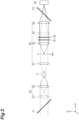
- FIG. 2 is a diagram illustrating a configuration example of the irradiation optical system 20 and the imaging optical system 30 of the observation apparatus 1.
- the action of convergence or collimation of the object light by each lens constituting the irradiation optical system 20 or the imaging optical system 30 is illustrated by a dashed line when viewed in the y axis direction, and illustrated by a solid line when viewed in the x axis direction.
- the irradiation optical system 20 includes lenses 21 and 22.
- the lens 21 is a cylindrical lens.
- a rear focal point of the lens 21 coincides with a front focal point of the lens 22.
- a rear focal point of the lens 22 is located at a position through which the observation object 2 passes.
- the object light output from the beam splitter 71 is converged by the lens 21, and then input to the lens 22 as diverging light, and collimated by the lens 22.
- the object light output from the beam splitter 71 is input to the lens 22 without being converged or diverged by the lens 21, and converged by the lens 22.
- the irradiation optical system 20 can focus the object light and irradiate a line-shaped region in the direction (y axis direction) perpendicular to the moving direction (x axis direction) of the observation object 2 with the object light. That is, the irradiation optical system 20 can simultaneously irradiate the observation object 2 with the object light from various directions (multiple directions).
- the imaging optical system 30 includes lenses 31 to 34.
- each of the lenses 32 to 34 is a cylindrical lens.
- a front focal point of the lens 31 is located at a position through which the observation object 2 passes.
- a rear focal point of the lens 31 is located on a plane FP.
- the plane FP is a plane on which the Fourier transform image of the observation object 2 is formed by the lens 31.
- a front focal point of the lens 32 is located on the plane FP.
- a rear focal point of the lens 32 is located at the position of the lens 33.
- a front focal point of the lens 33 is located on the plane FP.
- a rear focal point of the lens 33 is located on the imaging plane of the imaging unit 50.
- a front focal point of the lens 34 is located at the position of the lens 33.
- a rear focal point of the lens 34 is located on the imaging plane of the imaging unit 50.
- the object light emitted from the observation object 2 is collimated by the lens 31, and converged by the lens 33.
- the object light emitted from the Fourier transform plane FP is collimated by the lens 32, and converged by the lens 34.
- the imaging optical system 30 can set the observation object 2 and the imaging plane of the imaging unit 50 in a positional relationship of Fourier transform in the direction (x axis direction) parallel to the moving direction of the observation object 2, and further, can set the observation object 2 and the imaging plane of the imaging unit 50 in a positional relationship conjugate to each other in the direction (y axis direction) perpendicular to the moving direction of the observation object 2.
- the analysis unit 60 can obtain the time series data of the complex amplitude image of the object light on the imaging plane.
- the complex amplitude image obtained here is the Fourier transform image in the x axis direction and the real image in the y axis direction.
- the analysis unit 60 can obtain the complex amplitude image (real image) for each irradiation direction of the object light to the observation object 2 by the irradiation optical system 20 by performing processing such as Fourier transform on the time series data of the intensity image of the interference light acquired by the imaging unit 50, and can acquire a three-dimensional distribution of a refractive index of the observation object 2 (see Patent Document 1 and Non Patent Document 1).
- FIG. 2 also illustrates a neutral density filter 35 inserted on the optical path of the object light and a shield 36 which can be inserted on the optical path of the object light.
- the neutral density filter 35 is an element for adjusting the intensity of the object light reaching the imaging plane of the imaging unit 50.
- the shield 36 is an element for preventing the object light from entering the imaging plane of the imaging unit 50 when it is inserted on the optical path. When the intensity image of the interference light is acquired by the imaging unit 50, the shield 36 is removed from the optical path of the object light.
- a moving speed of the observation object 2 is set to V
- a wavenumber component in the x axis direction of the object light before interacting with the observation object 2 is set to k x in
- a wavenumber component in the x axis direction of the object light after interacting with the observation object 2 is set to k x out .
- a numerical aperture of the lens 22 at the final stage of the irradiation optical system 20 is set to NA in
- a numerical aperture of the lens 31 at the first stage of the imaging optical system 30 is set to NA out
- a wavelength of the light is set to ⁇ .
- a maximum value ⁇ f max of the Doppler shift amount ⁇ f is represented by the following Formula (2)
- a minimum value ⁇ f min of the Doppler shift amount ⁇ f is represented by the following Formula (3). Therefore, the Doppler shift amount ⁇ f of the optical frequency of the object light reaching the imaging plane of the imaging unit 50 is distributed in a range of [- ⁇ f max , ⁇ f max ].
- ⁇ max NA in + NA out ⁇ V ⁇
- the time series data of the complex amplitude image of the object light on the imaging plane of the imaging unit 50 is set to U obj (t).
- the time series data of the complex amplitude image of the reference light on the imaging plane of the imaging unit 50 is set to U ref (t).
- U ref (t) is represented as follows using the heterodyne frequency f 0 .
- U ref t U 0 ⁇ exp ⁇ i 2 ⁇ f 0 t
- the time series data I(t) of the intensity image of the interference light acquired by the imaging unit 50 is represented by the following Formula (4) and Formula (5) (Formulas (5a) to (5d)).
- i is an imaginary unit
- ⁇ is a circular constant
- t is a time variable. The notation of a variable representing a position in each image is omitted.
- I obj (t) (Formula (5a)) includes frequency components in a range of [-2 ⁇ f max , 2 ⁇ f max ].
- I ref (t) (Formula (5b)) includes only DC components when U 0 does not change with time.
- I cross (t) (Formula (5c)) includes frequency components in a range of [- ⁇ f max + f 0 , ⁇ f max + f 0 ].
- I cross ⁇ (t) (Formula (5d)) includes frequency components in a range of [- ⁇ f max - f 0 , ⁇ f max - f 0 ].
- the time series data of I cross (t) or I cross ⁇ (t) can be measured. Further, the time series data U obj (t) of the complex amplitude image of the object light can be obtained from Formula (5c) or Formula (5d).
- the frame rate when the imaging unit 50 acquires the time series data I(t) of the intensity image of the interference light can be made lower than 8 ⁇ f max by improving the content of processing by the analysis unit 60.
- Re[ ⁇ (t)] being a real part of the function ⁇ (t) is represented by the following Formula (8).
- Formula (8) Re[ ⁇ (t)] can be obtained based on the time series data I(t) of the intensity image of the interference light on the imaging plane of the imaging unit 50 and the time series data I ref (t) of the intensity image of the reference light on the imaging plane of the imaging unit 50. Since both I(t) and I ref (t) can be measured, Re[ ⁇ (t)] can be obtained from the measured values.
- the time series data I ref (t) of the intensity image of the reference light can be measured, for example, by inserting the shield 36 on the optical path of the object light in the interference optical system as illustrated in FIG. 2 before or after the measurement so that only the reference light out of the object light and the reference light reaches the imaging plane of the imaging unit 50, when the data does not change with time during and before and after the measurement.
- the intensity image of the reference light corresponding to the time series data I(t) of the intensity image of the interference light is referred to as the time series data I ref (t) of the intensity image of the reference light which does not change with time.
- a beam splitter 75 may be provided on the optical path of the reference light in the interference optical system, a part of the reference light may be split and extracted by the beam splitter 75, and the time series data I ref (t) of the intensity image of the extracted reference light may be acquired by another second imaging unit 51.
- the time series data I ref (t) of the intensity image of the reference light acquired by the second imaging unit 51 may be equal to the time series data I ref (t) of the intensity image of the reference light acquired by the imaging unit 50 when only the reference light reaches the imaging unit 50.
- the second imaging unit 51 may have a configuration similar to that of the imaging unit 50.
- Im[x(t)] being an imaginary part of the function ⁇ (t) and Re[x(t)] described above have a relationship represented by the Kramers-Kronig relations (hereinafter referred to as the "KK relations") of the following Formula (9) and Formula (10). Therefore, by using Formula (10), Im[x(t)] can be obtained from Re[ ⁇ (t)].
- the function ⁇ (t) can be obtained, the time series data U obj (t) of the complex amplitude image of the object light can be obtained from the function ⁇ (t) using Formula (6) and Formula (7).
- Re ⁇ t 1 ⁇ p . ⁇ .
- a transmittance and a reflectance of the beam splitter 71 or the beam splitter 72 may be set to appropriate values.
- the object light may be attenuated by the neutral density filter 35 provided on the optical path of the object light in the interference optical system.
- the neutral density filter 35 is preferably provided on the optical path where the object light is collimated (for example, between the lens 32 and the lens 33 or between the beam splitter 71 and the lens 21).
- the convolution theorem holds for two functions f 1 (t) and f 2 (t). That is, when a Fourier transform of f 1 (t) is set to F 1 ( ⁇ ) and a Fourier transform of f 2 (t) is set to F 2 ( ⁇ ), a product of f 1 (t) and f 2 (t) is equal to a Fourier transform of convolution of F 1 ( ⁇ ) and P 2 ( ⁇ ).
- the heterodyne frequency f 0 set by the modulation unit 40 may be set to ⁇ f max or more. That is, as can be seen from the above Formula (6), when the frequency range [- ⁇ f max , ⁇ f max ] of U obj (t) is shifted by the heterodyne frequency f 0 of U ref (t), a negative frequency component may not be present after the shift.
- the imaging unit 50 acquires the time series data I(t) of the intensity image of the interference light at a frame rate lower than that in the conventional art, and the time series data U obj (t) of the complex amplitude image of the object light can be reproduced with high accuracy.
- the frame rate of the imaging unit 50 may be 4 ⁇ f max . This is one half of the frame rate conventionally required.
- I(t) and I ref (t) acquired by the imaging unit 50 it is preferable to perform a Fourier transform, a padding process of enlarging a frequency domain after the Fourier transform and giving a predetermined value (for example, 0) to the enlarged domain, and an inverse Fourier transform after the padding process, and use the data after these processes in Formula (8).
- U obj (t) obtained from ⁇ (t) it is preferable to perform a Fourier transform, a cropping process for extracting a part of a frequency domain after the Fourier transform, and an inverse Fourier transform after the cropping process, and use the data after these processes in subsequent processes.
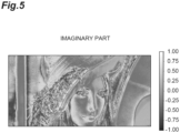
- FIG. 4 is a diagram showing the real part of the original image
- FIG. 5 is a diagram showing the imaginary part of the original image.
- the number of pixels of the original image is 256 ⁇ 512.
- FIG. 6 is a diagram showing a frequency distribution of the intensity image I(t) of the interference light on the imaging plane of the imaging unit 50.
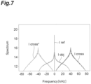
- FIG. 7 is a diagram showing respective frequency distributions of I obj (t), I ref (t), I cross (t), and I cross ⁇ (t) on the imaging plane of the imaging unit 50.
- I obj (t) includes frequency components in a range of [-80 kHz, 80 kHz] and has a peak at a frequency position of 0 kHz.
- the frequency distribution of I ref (t) is constant with time and includes only DC components.
- I cross (t) includes frequency components in a range of [0 kHz, 80 kHz] and has a peak at a frequency position of 40 kHz.
- I cross ⁇ (t) includes frequency components in a range of [-80 kHz, 0 kHz] and has a peak at a frequency position of -40 kHz.
- the frequency range of each of I cross (t) and I cross ⁇ (t) overlaps with the frequency range of I obj (t). Therefore, I cross (t) and I cross ⁇ (t) cannot be measured separately from I obj (t).
- FIG. 8 is a diagram showing a frequency distribution of I cross (t) obtained by a conventional example of extracting a frequency range of [0 kHz, 80 kHz] from FIG. 6 .
- FIG. 9 is a diagram showing a frequency distribution of I cross (t) obtained by an example using the KK relations.
- the frequency distribution of I obj (t) is superimposed on the original frequency distribution of I cross (t).
- there is no influence of the frequency distribution of I obj (t) there is no influence of the frequency distribution of I obj (t), and the original frequency distribution of I cross (t) is obtained.
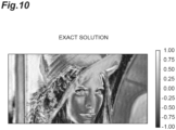
- FIG. 10 is a diagram showing an image of an exact solution.
- FIG. 11 is a diagram showing an image obtained by the conventional example.
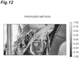
- FIG. 12 is a diagram showing an image obtained by the example.
- Each image in FIG. 10 to FIG. 12 is the real part of the complex amplitude image obtained when the irradiation direction of the object light to the original image by the irradiation optical system 20 is set to 34° with respect to the z axis.
- FIG. 13 is a diagram showing a difference between the complex amplitude image obtained by the conventional example and the image of the exact solution.
- FIG. 14 is a diagram showing a difference between the complex amplitude image obtained by the example and the image of the exact solution.
- Each image in FIG. 13 and FIG. 14 is an image of a square of an absolute value of the difference between the two images.
- an error is large.
- a camera whose frame rate is lower than that of the conventional method can be used as the imaging unit.
- equivalent information (image quality) at a frame rate of 1/2 compared to the conventional method.
- image data obtained by imaging can be reduced, a capacity of a storage unit necessary for storing data can be reduced, and a load of data processing can be reduced.
- an inexpensive camera can be used as the imaging unit.
- a throughput (number/second) of the observation of the observation object can be improved by two times, and the number of sample records per one apparatus can be improved by two times.
- the observation apparatus and the observation method are not limited to the embodiments and configuration examples described above, and various other modifications are possible.
- the observation apparatus of the above embodiment includes (1) a light source for outputting light; (2) an interference optical system for splitting the light output from the light source into object light and reference light, and combining and outputting the object light passed through a moving observation object and the reference light; (3) a modulation unit provided on an optical path of the object light or the reference light from splitting to combining in the interference optical system, and for shifting an optical frequency of the object light or the reference light by a heterodyne frequency f 0 ; (4) an imaging unit having an imaging plane disposed at a position where an image of the observation object is formed by the object light output from the interference optical system, and for acquiring an intensity image of interference light by the object light and the reference light output from the interference optical system and reaching the imaging plane; and (5) an analysis unit for obtaining time series data of a complex amplitude image of the object light on the imaging plane based on time series data of the intensity image of the interference light on the imaging plane, and when a maximum value of a Doppler shift amount of the optical frequency based on interaction with
- the heterodyne frequency f 0 may be set to less than 3 ⁇ f max in the modulation unit.
- the interference optical system may include (1) an irradiation optical system for, when irradiating the observation object with the object light, focusing the object light and irradiating a line-shaped region in a direction perpendicular to a moving direction of the observation object with the object light; and (2) an imaging optical system for, when forming the image of the observation object by the object light emitted from the observation object on the imaging plane, setting a positional relationship of Fourier transform between the observation object and the imaging plane in a direction parallel to the moving direction of the observation object, and setting a positional relationship conjugate to each other between the observation object and the imaging plane in a direction perpendicular to the moving direction of the observation object, and the analysis unit may obtain the complex amplitude image for each irradiation direction of the object light to the observation object by the irradiation optical system, and may acquire a three-dimensional distribution of a refractive index of the observation object.
- the analysis unit may obtain the real part of the function ⁇ (t) using the intensity image of the reference light acquired when only the reference light out of the object light and the reference light reaches the imaging plane of the imaging unit in a state where a shield is placed on the optical path of the object light in the interference optical system.
- the real part of the function ⁇ (t) may be obtained using the intensity image of the reference light acquired when only the reference light out of the object light and the reference light reaches the imaging plane of the imaging unit in a state where a shield is placed on the optical path of the object light in the interference optical system.
- the above observation apparatus may further include a beam splitter provided on the optical path of the reference light in the interference optical system, and for splitting and extracting a part of the reference light; and a second imaging unit for acquiring the intensity image of the reference light extracted by the beam splitter, and the analysis unit may obtain the real part of the function ⁇ (t) using the time series data I ref (t) of the intensity image of the reference light acquired by the second imaging unit.
- a beam splitter provided on the optical path of the reference light in the interference optical system, and for splitting and extracting a part of the reference light
- a second imaging unit for acquiring the intensity image of the reference light extracted by the beam splitter
- the analysis unit may obtain the real part of the function ⁇ (t) using the time series data I ref (t) of the intensity image of the reference light acquired by the second imaging unit.
- the above observation method may further use a beam splitter provided on the optical path of the reference light in the interference optical system, and for splitting and extracting a part of the reference light; and a second imaging unit for acquiring the intensity image of the reference light extracted by the beam splitter, and the real part of the function ⁇ (t) may be obtained using the time series data I ref (t) of the intensity image of the reference light acquired by the second imaging unit.
- a beam splitter provided on the optical path of the reference light in the interference optical system, and for splitting and extracting a part of the reference light
- a second imaging unit for acquiring the intensity image of the reference light extracted by the beam splitter, and the real part of the function ⁇ (t) may be obtained using the time series data I ref (t) of the intensity image of the reference light acquired by the second imaging unit.
- the embodiments can be used as an observation apparatus and an observation method capable of using a low-speed camera as an imaging unit when observing a moving observation object.
- 1, 1A - observation apparatus 2 - observation object, 10 - light source unit, 20 - irradiation optical system, 21, 22 - lens, 30 - imaging optical system, 31 - 34 - lens, 35 - neutral density filter, 36 - shield, 40 - modulation unit, 41, 42 - acousto-optic element, 50, 51 - imaging unit, 60 - analysis unit, 71, 72 - beam splitter, 73, 74 - mirror, 75 - beam splitter.
Landscapes
- Chemical & Material Sciences (AREA)
- Physics & Mathematics (AREA)
- Analytical Chemistry (AREA)
- General Physics & Mathematics (AREA)
- Biochemistry (AREA)
- Life Sciences & Earth Sciences (AREA)
- Health & Medical Sciences (AREA)
- General Health & Medical Sciences (AREA)
- Dispersion Chemistry (AREA)
- Immunology (AREA)
- Pathology (AREA)
- Engineering & Computer Science (AREA)
- Signal Processing (AREA)
- Optics & Photonics (AREA)
- Investigating Or Analysing Materials By Optical Means (AREA)
Abstract
Description
- The present disclosure relates to an observation apparatus and an observation method.
- An observation apparatus described in
Patent Document 1 andNon Patent Document 1 splits light output from a light source into object light and reference light, combines the object light passed through a moving observation object and the reference light having an optical frequency shifted by a heterodyne frequency, and causes heterodyne interference between the object light and the reference light. Further, the observation apparatus can acquire time series data of a complex amplitude image of the object light on an imaging plane based on time series data of an intensity image of interference light reaching the imaging plane of a camera. - The above observation apparatus needs to use a camera having a higher frame rate as the observation object moves faster. For example, the above observation apparatus is used when observing a cell (observation object) flowing at a speed of several m/sec along a flow path in a flow cytometer, and in this case, it is desirable to use a high-speed camera having a frame rate exceeding 100 kfps.
- Patent Document 1: International Publication
No. 2013/065796 -
- Non Patent Document 1: H. Iwai, T. Yamauchi, M. Miwa, Y. Yamashita, "Doppler-spectrally encoded imaging of translational objects", Optics Communications, Vol.319, pp.159-169 (2014)
- Non Patent Document 2: Y. Baek, K. Lee, S. Shin, Y. Park, "Kramers-Kronig holographic imaging for high-space-bandwidth product", Optica, Vol.6 No.1, pp.45-51 (2019)
- However, when the high-speed camera is used, image data obtained by imaging becomes enormous, a capacity of a storage unit for storing data also becomes large, and a load of data processing also becomes large. Further, the high-speed camera is expensive.
- In addition,
Non Patent Document 2 describes a technique capable of acquiring a phase image equivalent to a conventional one even when a spatial sampling period is increased (that is, when a pixel pitch in the imaging plane of the camera is increased). However, the above technique cannot lower the frame rate of the camera when observing the moving observation object. - An object of an embodiment is to provide an observation apparatus and an observation method capable of using a low-speed camera as an imaging unit when observing a moving observation object.
- An embodiment is an observation apparatus. The observation apparatus includes (1) a light source for outputting light; (2) an interference optical system for splitting the light output from the light source into object light and reference light, and combining and outputting the object light passed through a moving observation object and the reference light; (3) a modulation unit provided on an optical path of the object light or the reference light from splitting to combining in the interference optical system, and for shifting an optical frequency of the object light or the reference light by a heterodyne frequency f0; (4) an imaging unit having an imaging plane disposed at a position where an image of the observation object is formed by the object light output from the interference optical system, and for acquiring an intensity image of interference light by the object light and the reference light output from the interference optical system and reaching the imaging plane; and (5) an analysis unit for obtaining time series data of a complex amplitude image of the object light on the imaging plane based on time series data of the intensity image of the interference light on the imaging plane, and when a maximum value of a Doppler shift amount of the optical frequency based on interaction with the observation object in the object light reaching the imaging plane is set to Afmax, the modulation unit sets the heterodyne frequency f0 to Δfmax or more, and the analysis unit (a) obtains a real part of a function χ(t) = log [1 + Uobj(t) / Uref(t)], defined by time series data Uobj(t) of the complex amplitude image of the object light on the imaging plane and time series data Uref(t) of the complex amplitude image of the reference light on the imaging plane, based on time series data I(t) of the intensity image of the interference light on the imaging plane and time series data Iref(t) of the intensity image of the reference light on the imaging plane, (b) obtains an imaginary part of the function χ(t) from the real part of the function χ(t) using Kramers-Kronig relations, and (c) obtains the time series data Uobj(t) of the complex amplitude image of the object light on the imaging plane based on the function χ(t).
- An embodiment is an observation method. The observation method uses the light source; the interference optical system; the modulation unit; and the imaging unit of the above configuration, and the method includes (a) when a maximum value of a Doppler shift amount of the optical frequency based on interaction with the observation object in the object light reaching the imaging plane is set to Afmax, setting the heterodyne frequency f0 to Δfmax or more by the modulation unit, and obtaining time series data of the intensity image of the interference light on the imaging plane by the imaging unit; (b) obtaining a real part of a function χ(t) = log [1 + Uobj(t) / Uref(t)], defined by time series data Uobj(t) of the complex amplitude image of the object light on the imaging plane and time series data Uref(t) of the complex amplitude image of the reference light on the imaging plane, based on time series data I(t) of the intensity image of the interference light on the imaging plane and time series data Iref(t) of the intensity image of the reference light on the imaging plane; (c) obtaining an imaginary part of the function χ(t) from the real part of the function χ(t) using Kramers-Kronig relations; and (d) obtaining the time series data Uobj(t) of the complex amplitude image of the object light on the imaging plane based on the function χ(t).
- According to the observation apparatus and the observation method of the embodiments, it is possible to use a low-speed camera as an imaging unit when observing a moving observation object.
-
- [
FIG. 1] FIG. 1 is a diagram illustrating a configuration of anobservation apparatus 1. - [
FIG. 2] FIG. 2 is a diagram illustrating a configuration example of an irradiationoptical system 20 and an imagingoptical system 30 of theobservation apparatus 1. - [
FIG. 3] FIG. 3 is a diagram illustrating a configuration of anobservation apparatus 1A of a modification. - [
FIG. 4] FIG. 4 is a diagram showing a real part of an original image. - [
FIG. 5] FIG. 5 is a diagram showing an imaginary part of the original image. - [
FIG. 6] FIG. 6 is a diagram showing a frequency distribution of an intensity image I(t) of interference light on an imaging plane of animaging unit 50. - [
FIG. 7] FIG. 7 is a diagram showing frequency distributions of Iobj(t), Iref(t), Icross(t), and Icross ∗(t) on the imaging plane of theimaging unit 50. - [
FIG. 8] FIG. 8 is a diagram showing a frequency distribution of Icross(t) obtained by a conventional example of extracting a frequency range of [0 kHz, 80 kHz] fromFIG. 6 . - [
FIG. 9] FIG. 9 is a diagram showing a frequency distribution of Icross(t) obtained by an example using the KK relations. - [
FIG. 10] FIG. 10 is a diagram showing an image of an exact solution. - [
FIG. 11] FIG. 11 is a diagram showing an image obtained by the conventional example. - [
FIG. 12] FIG. 12 is a diagram showing an image obtained by the example. - [
FIG. 13] FIG. 13 is a diagram showing a difference between a complex amplitude image obtained by the conventional example and the image of the exact solution. - [
FIG. 14] FIG. 14 is a diagram showing a difference between a complex amplitude image obtained by the example and the image of the exact solution. - Hereinafter, embodiments of an observation apparatus and an observation method will be described in detail with reference to the accompanying drawings. In the description of the drawings, the same elements will be denoted by the same reference signs, and redundant description will be omitted. The present invention is not limited to these examples.
-
FIG. 1 is a diagram illustrating a configuration of anobservation apparatus 1. Theobservation apparatus 1 includes alight source unit 10, an irradiationoptical system 20, an imagingoptical system 30, amodulation unit 40, animaging unit 50, ananalysis unit 60,beam splitters mirrors light source unit 10 to theimaging unit 50 are optically coupled to each other. Theimaging unit 50 and theanalysis unit 60 are electrically coupled to each other. - The
observation apparatus 1 can be suitably used, for example, when observing a cell (observation object 2) flowing in one direction along a flow path in a flow cytometer. Theobservation object 2 is moving in a space between the irradiationoptical system 20 and the imagingoptical system 30. - Hereinafter, as illustrated in the diagram, the
observation apparatus 1 will be described by using an xyz orthogonal coordinate system. The z axis is set in a direction parallel to an optical axis of the irradiationoptical system 20 and the imagingoptical system 30. It is assumed that theobservation object 2 moves in one direction perpendicular to the z axis, and the x axis is set in a direction parallel to the moving direction. The y axis is set in a direction perpendicular to both the x axis and the z axis. - The
light source unit 10 outputs light with which theobservation object 2 is irradiated. Thelight source unit 10 outputs temporally and spatially coherent light, and includes, for example, a He-Ne laser light source. It is preferable that thelight source unit 10 includes a beam expander, and outputs collimated light whose beam diameter is increased by the beam expander. - The
beam splitter 71 is optically coupled to thelight source unit 10. Thebeam splitter 71 splits the light reaching from thelight source unit 10 into two light beams, outputs one split light as object light to the irradiationoptical system 20, and outputs the other split light as reference light to themodulation unit 40. - The irradiation
optical system 20 is optically coupled to thebeam splitter 71. The irradiationoptical system 20 receives the object light reaching from thebeam splitter 71, and irradiates theobservation object 2 with the object light. - The imaging
optical system 30 receives light (transmitted light, scattered light, or the like) generated in theobservation object 2 by the object light irradiation onto theobservation object 2 by the irradiationoptical system 20, and forms an image of theobservation object 2 on an imaging plane of theimaging unit 50 by the received object light. - The
modulation unit 40 is optically coupled to thebeam splitter 71. Themodulation unit 40 receives the reference light reaching from thebeam splitter 71, and shifts an optical frequency of the reference light by a heterodyne frequency f0. - The
modulation unit 40 may include, for example, a first acousto-optic element 41 and a second acousto-optic element 42. The first acousto-optic element 41 diffracts the reference light reaching from thebeam splitter 71 by a first modulation signal, and outputs the diffracted reference light to the second acousto-optic element 42. - The second acousto-
optic element 42 diffracts the reference light reaching from the first acousto-optic element 41 by a second modulation signal, and outputs the diffracted reference light to themirror 73. The reference light output from the second acousto-optic element 42 is sequentially reflected by themirror 73 and themirror 74, and reaches thebeam splitter 72. - A frequency of the first modulation signal provided to the first acousto-
optic element 41 and a frequency of the second modulation signal provided to the second acousto-optic element 42 are slightly different from each other. For example, the frequency of the first modulation signal is set to 40 MHz, the frequency of the second modulation signal is set to 40.040 MHz, and a difference between them is 40 kHz. Each of the first modulation signal and the second modulation signal is a sinusoidal wave. - In addition, the
modulation unit 40 is not necessarily configured by two elements of the first acousto-optic element 41 and the second acousto-optic element 42. That is, themodulation unit 40 may have a function of shifting the optical frequency of the reference light by the predetermined heterodyne frequency, and themodulation unit 40 may include one modulation element, or may include three or more modulation elements. Further, themodulation unit 40 may be disposed on the optical path of the object light, and may shift the optical frequency of the object light by the heterodyne frequency. - The
beam splitter 72 is optically coupled to the imagingoptical system 30, and receives the object light reaching from the imagingoptical system 30. Further, thebeam splitter 72 is optically coupled to themirror 74, and receives the reference light reaching from themirror 74. Thebeam splitter 72 combines the received object light and the reference light, outputs the combined light on the same axis, and causes heterodyne interference of the light beams to generate interference light. The optical system from thebeam splitter 71 to thebeam splitter 72 constitutes an interference optical system. - The
imaging unit 50 is optically coupled to thebeam splitter 72. Theimaging unit 50 receives the interference light generated by the object light and the reference light output and reaching from thebeam splitter 72. The imaging plane of theimaging unit 50 is disposed at a position where an image of theobservation object 2 is formed by the object light output and reaching from the imagingoptical system 30. The image formed here may be a real image of theobservation object 2, or a Fourier transform image thereof. Theimaging unit 50 acquires an intensity image of the interference light by the object light and the reference light output from thebeam splitter 72 and reaching the imaging plane. - The
analysis unit 60 is electrically coupled to theimaging unit 50. Theanalysis unit 60 inputs data of the intensity image of the interference light acquired by theimaging unit 50. Theanalysis unit 60 obtains time series data of a complex amplitude image of the object light on the imaging plane on the basis of time series data of the intensity image of the interference light on the imaging plane of theimaging unit 50. - The
analysis unit 60 includes an input unit for inputting the data of the intensity image of the interference light from theimaging unit 50, a storage unit (for example, hard disk drive, RAM, and the like) for storing the input data of the intensity image of the interference light, the data of the complex amplitude image of processing results, and the like, an operation unit (for example, CPU, DSP, FPGA, and the like) for processing the data, and a display unit (for example, liquid crystal display and the like) for displaying the intensity image of the interference light, the complex amplitude image of the processing results, and the like. Theanalysis unit 60 is, for example, a computer, a smart device, or a cloud computing. -
FIG. 2 is a diagram illustrating a configuration example of the irradiationoptical system 20 and the imagingoptical system 30 of theobservation apparatus 1. In this diagram, the action of convergence or collimation of the object light by each lens constituting the irradiationoptical system 20 or the imagingoptical system 30 is illustrated by a dashed line when viewed in the y axis direction, and illustrated by a solid line when viewed in the x axis direction. - The irradiation
optical system 20 includeslenses lens 21 is a cylindrical lens. A rear focal point of thelens 21 coincides with a front focal point of thelens 22. A rear focal point of thelens 22 is located at a position through which theobservation object 2 passes. - When viewed in the y axis direction, as indicated by the dashed line, the object light output from the
beam splitter 71 is converged by thelens 21, and then input to thelens 22 as diverging light, and collimated by thelens 22. When viewed in the x axis direction, as indicated by the solid line, the object light output from thebeam splitter 71 is input to thelens 22 without being converged or diverged by thelens 21, and converged by thelens 22. - Thus, the irradiation
optical system 20 can focus the object light and irradiate a line-shaped region in the direction (y axis direction) perpendicular to the moving direction (x axis direction) of theobservation object 2 with the object light. That is, the irradiationoptical system 20 can simultaneously irradiate theobservation object 2 with the object light from various directions (multiple directions). - The imaging
optical system 30 includeslenses 31 to 34. In these lenses, each of thelenses 32 to 34 is a cylindrical lens. A front focal point of thelens 31 is located at a position through which theobservation object 2 passes. A rear focal point of thelens 31 is located on a plane FP. The plane FP is a plane on which the Fourier transform image of theobservation object 2 is formed by thelens 31. - A front focal point of the
lens 32 is located on the plane FP. A rear focal point of thelens 32 is located at the position of thelens 33. A front focal point of thelens 33 is located on the plane FP. A rear focal point of thelens 33 is located on the imaging plane of theimaging unit 50. A front focal point of thelens 34 is located at the position of thelens 33. A rear focal point of thelens 34 is located on the imaging plane of theimaging unit 50. - When viewed in the y axis direction, as indicated by the dashed line, the object light emitted from the
observation object 2 is collimated by thelens 31, and converged by thelens 33. When viewed in the x axis direction, as indicated by the solid line, the object light emitted from the Fourier transform plane FP is collimated by thelens 32, and converged by thelens 34. - Thus, the imaging
optical system 30 can set theobservation object 2 and the imaging plane of theimaging unit 50 in a positional relationship of Fourier transform in the direction (x axis direction) parallel to the moving direction of theobservation object 2, and further, can set theobservation object 2 and the imaging plane of theimaging unit 50 in a positional relationship conjugate to each other in the direction (y axis direction) perpendicular to the moving direction of theobservation object 2. - When the irradiation
optical system 20 and the imagingoptical system 30 have the above configurations, theanalysis unit 60 can obtain the time series data of the complex amplitude image of the object light on the imaging plane. The complex amplitude image obtained here is the Fourier transform image in the x axis direction and the real image in the y axis direction. - Further, the
analysis unit 60 can obtain the complex amplitude image (real image) for each irradiation direction of the object light to theobservation object 2 by the irradiationoptical system 20 by performing processing such as Fourier transform on the time series data of the intensity image of the interference light acquired by theimaging unit 50, and can acquire a three-dimensional distribution of a refractive index of the observation object 2 (seePatent Document 1 and Non Patent Document 1). - In addition,
FIG. 2 also illustrates aneutral density filter 35 inserted on the optical path of the object light and ashield 36 which can be inserted on the optical path of the object light. Theneutral density filter 35 is an element for adjusting the intensity of the object light reaching the imaging plane of theimaging unit 50. Theshield 36 is an element for preventing the object light from entering the imaging plane of theimaging unit 50 when it is inserted on the optical path. When the intensity image of the interference light is acquired by theimaging unit 50, theshield 36 is removed from the optical path of the object light. These functions will be described later. - In the
observation apparatus 1 described above, a moving speed of theobservation object 2 is set to V, a wavenumber component in the x axis direction of the object light before interacting with theobservation object 2 is set to kx in, and a wavenumber component in the x axis direction of the object light after interacting with theobservation object 2 is set to kx out. In this case, a Doppler shift amount Δf of the optical frequency of the object light generated by the interaction with theobservation object 2 is represented by the following Formula (1).
[Formula 1]
- A numerical aperture of the
lens 22 at the final stage of the irradiationoptical system 20 is set to NAin, a numerical aperture of thelens 31 at the first stage of the imagingoptical system 30 is set to NAout, and a wavelength of the light is set to λ. In this case, a maximum value Δfmax of the Doppler shift amount Δf is represented by the following Formula (2), and a minimum value Δfmin of the Doppler shift amount Δf is represented by the following Formula (3). Therefore, the Doppler shift amount Δf of the optical frequency of the object light reaching the imaging plane of theimaging unit 50 is distributed in a range of [-Δfmax, Δfmax].
[Formula 2]

- The time series data of the complex amplitude image of the object light on the imaging plane of the
imaging unit 50 is set to Uobj(t). The time series data of the complex amplitude image of the reference light on the imaging plane of theimaging unit 50 is set to Uref(t). Uref(t) is represented as follows using the heterodyne frequency f0.
- The time series data I(t) of the intensity image of the interference light acquired by the
imaging unit 50 is represented by the following Formula (4) and Formula (5) (Formulas (5a) to (5d)). In addition, i is an imaginary unit, π is a circular constant, and t is a time variable. The notation of a variable representing a position in each image is omitted.
[Formula 4]


- Iobj(t) (Formula (5a)) includes frequency components in a range of [-2Δfmax, 2Δfmax]. Iref(t) (Formula (5b)) includes only DC components when U0 does not change with time. Icross(t) (Formula (5c)) includes frequency components in a range of [-Δfmax + f0, Δfmax + f0]. Icross ∗(t) (Formula (5d)) includes frequency components in a range of [-Δfmax - f0, Δfmax - f0].
- When the frequency range of Icross(t) or Icross ∗(t) does not overlap with the frequency range of Iobj(t), the time series data of Icross(t) or Icross ∗(t) can be measured. Further, the time series data Uobj(t) of the complex amplitude image of the object light can be obtained from Formula (5c) or Formula (5d).
- In order to prevent the frequency range of Icross(t) or Icross ∗(t) from overlapping with the frequency range of Iobj(t), it is necessary to set the heterodyne frequency f0 to f0 ≥ 3Δfmax. In addition, when f0 = 3Δfmax, the maximum frequency of the time series data I(t) of the intensity image of the interference light is 4Δfmax. Therefore, from the Nyquist sampling theorem, when the time series data I(t) of the intensity image of the interference light is acquired by the
imaging unit 50 at a frame rate of twice the maximum frequency (8Δfmax), the time series data Uobj(t) of the complex amplitude image of the object light can be reproduced with high accuracy. - In the observation apparatus and the observation method described below, the frame rate when the
imaging unit 50 acquires the time series data I(t) of the intensity image of the interference light can be made lower than 8Δfmax by improving the content of processing by theanalysis unit 60. - A function β(t) represented by the following Formula (6) is defined using the time series data Uobj(t) of the complex amplitude image of the object light on the imaging plane of the
imaging unit 50 and the time series data Uref(t) of the complex amplitude image of the reference light on the imaging plane of theimaging unit 50. Further, a function χ(t) represented by the following Formula (7) is defined using the function β(t).
[Formula 6]

- Re[χ(t)] being a real part of the function χ(t) is represented by the following Formula (8). As shown in Formula (8), Re[χ(t)] can be obtained based on the time series data I(t) of the intensity image of the interference light on the imaging plane of the
imaging unit 50 and the time series data Iref(t) of the intensity image of the reference light on the imaging plane of theimaging unit 50. Since both I(t) and Iref(t) can be measured, Re[χ(t)] can be obtained from the measured values.
[Formula 8]
- The time series data Iref(t) of the intensity image of the reference light can be measured, for example, by inserting the
shield 36 on the optical path of the object light in the interference optical system as illustrated inFIG. 2 before or after the measurement so that only the reference light out of the object light and the reference light reaches the imaging plane of theimaging unit 50, when the data does not change with time during and before and after the measurement. In addition, in Formula (8), the intensity image of the reference light corresponding to the time series data I(t) of the intensity image of the interference light is referred to as the time series data Iref(t) of the intensity image of the reference light which does not change with time. - Further, when the time series data Iref(t) of the intensity image of the reference light changes with time, for example, as in a configuration of an
observation apparatus 1A illustrated inFIG. 3 , abeam splitter 75 may be provided on the optical path of the reference light in the interference optical system, a part of the reference light may be split and extracted by thebeam splitter 75, and the time series data Iref(t) of the intensity image of the extracted reference light may be acquired by anothersecond imaging unit 51. - The time series data Iref(t) of the intensity image of the reference light acquired by the
second imaging unit 51 may be equal to the time series data Iref(t) of the intensity image of the reference light acquired by theimaging unit 50 when only the reference light reaches theimaging unit 50. Thesecond imaging unit 51 may have a configuration similar to that of theimaging unit 50. - Im[x(t)] being an imaginary part of the function χ(t) and Re[x(t)] described above have a relationship represented by the Kramers-Kronig relations (hereinafter referred to as the "KK relations") of the following Formula (9) and Formula (10). Therefore, by using Formula (10), Im[x(t)] can be obtained from Re[χ(t)]. Thus, since the function χ(t) can be obtained, the time series data Uobj(t) of the complex amplitude image of the object light can be obtained from the function χ(t) using Formula (6) and Formula (7).
[Formula 9]

- In addition, it will be described that Re[χ(t)] and Im[χ(t)] have the relationship represented by the above Formula (9) and Formula (10). When β(t) satisfies the following Formula (11), χ(t) can be Taylor-expanded as in the following Formula (12). That is, χ(t) can be expanded by a power of β(t).
[Formula 11]

- In order to satisfy the above Formula (11), a transmittance and a reflectance of the
beam splitter 71 or thebeam splitter 72 may be set to appropriate values. Further, in order to satisfy the above Formula (11), as illustrated inFIG. 2 , the object light may be attenuated by theneutral density filter 35 provided on the optical path of the object light in the interference optical system. Theneutral density filter 35 is preferably provided on the optical path where the object light is collimated (for example, between thelens 32 and thelens 33 or between thebeam splitter 71 and the lens 21). - In general, the convolution theorem holds for two functions f1(t) and f2(t). That is, when a Fourier transform of f1(t) is set to F1(ω) and a Fourier transform of f2(t) is set to F2(ω), a product of f1(t) and f2(t) is equal to a Fourier transform of convolution of F1(ω) and P2(ω).
- From the convolution theorem and the above Formula (12), when the Fourier transform B(ω) of β(t) satisfies B(ω<0) = 0, the Fourier transform X(ω) of χ(t) satisfies X(ω<0) = 0. That is, when B(ω) = 0 in the range of ω < 0, X(ω) = 0 in the range of ω < 0. The inverse Fourier transform of the function X(ω) satisfying X(ω<0) = 0 is χ(t), and thus, Re[x(t)] and Im[x(t)] have the relationship of the KK relations represented by the above Formula (9) and Formula (10).
- In order to satisfy B(ω<0) = 0, the heterodyne frequency f0 set by the
modulation unit 40 may be set to Δfmax or more. That is, as can be seen from the above Formula (6), when the frequency range [-Δfmax, Δfmax] of Uobj(t) is shifted by the heterodyne frequency f0 of Uref(t), a negative frequency component may not be present after the shift. - When f0 is set to less than 3Δfmax, the
imaging unit 50 acquires the time series data I(t) of the intensity image of the interference light at a frame rate lower than that in the conventional art, and the time series data Uobj(t) of the complex amplitude image of the object light can be reproduced with high accuracy. For example, when f0 = Afmax, the maximum frequency of the time series data I(t) of the intensity image of the interference light is 2Δfmax, and thus, the frame rate of theimaging unit 50 may be 4Δfmax. This is one half of the frame rate conventionally required. - In addition, for each of I(t) and Iref(t) acquired by the
imaging unit 50, it is preferable to perform a Fourier transform, a padding process of enlarging a frequency domain after the Fourier transform and giving a predetermined value (for example, 0) to the enlarged domain, and an inverse Fourier transform after the padding process, and use the data after these processes in Formula (8). - Further, for Uobj(t) obtained from χ(t), it is preferable to perform a Fourier transform, a cropping process for extracting a part of a frequency domain after the Fourier transform, and an inverse Fourier transform after the cropping process, and use the data after these processes in subsequent processes.
- Next, simulation results will be described. In this case, the configuration of the observation apparatus illustrated in
FIG. 1 andFIG. 2 is assumed, and an original image (FIG. 4 andFIG. 5 ) parallel to the xy plane is moved in the x axis direction. The maximum value Δfmax of the Doppler shift amount of the object light reaching the imaging plane of theimaging unit 50 is set to 40 kHz, and the heterodyne frequency f0 by themodulation unit 40 is also set to 40 kHz.FIG. 4 is a diagram showing the real part of the original image, andFIG. 5 is a diagram showing the imaginary part of the original image. The number of pixels of the original image is 256 × 512. -
FIG. 6 is a diagram showing a frequency distribution of the intensity image I(t) of the interference light on the imaging plane of theimaging unit 50.FIG. 7 is a diagram showing respective frequency distributions of Iobj(t), Iref(t), Icross(t), and Icross ∗(t) on the imaging plane of theimaging unit 50. - Iobj(t) includes frequency components in a range of [-80 kHz, 80 kHz] and has a peak at a frequency position of 0 kHz. The frequency distribution of Iref(t) is constant with time and includes only DC components.
- Icross(t) includes frequency components in a range of [0 kHz, 80 kHz] and has a peak at a frequency position of 40 kHz. Icross ∗(t) includes frequency components in a range of [-80 kHz, 0 kHz] and has a peak at a frequency position of -40 kHz. The frequency range of each of Icross(t) and Icross ∗(t) overlaps with the frequency range of Iobj(t). Therefore, Icross(t) and Icross ∗(t) cannot be measured separately from Iobj(t).
-
FIG. 8 is a diagram showing a frequency distribution of Icross(t) obtained by a conventional example of extracting a frequency range of [0 kHz, 80 kHz] fromFIG. 6 .FIG. 9 is a diagram showing a frequency distribution of Icross(t) obtained by an example using the KK relations. In the conventional example, the frequency distribution of Iobj(t) is superimposed on the original frequency distribution of Icross(t). On the other hand, in the example, there is no influence of the frequency distribution of Iobj(t), and the original frequency distribution of Icross(t) is obtained. -
FIG. 10 is a diagram showing an image of an exact solution.FIG. 11 is a diagram showing an image obtained by the conventional example.FIG. 12 is a diagram showing an image obtained by the example. Each image inFIG. 10 to FIG. 12 is the real part of the complex amplitude image obtained when the irradiation direction of the object light to the original image by the irradiationoptical system 20 is set to 34° with respect to the z axis. -
FIG. 13 is a diagram showing a difference between the complex amplitude image obtained by the conventional example and the image of the exact solution.FIG. 14 is a diagram showing a difference between the complex amplitude image obtained by the example and the image of the exact solution. Each image inFIG. 13 andFIG. 14 is an image of a square of an absolute value of the difference between the two images. In the conventional example, an error is large. On the other hand, there is almost no error in the example. - As described above, according to the present embodiment, when observing the moving observation object, a camera whose frame rate is lower than that of the conventional method can be used as the imaging unit. For example, according to the present embodiment, it is possible to obtain equivalent information (image quality) at a frame rate of 1/2 compared to the conventional method.
- Therefore, image data obtained by imaging can be reduced, a capacity of a storage unit necessary for storing data can be reduced, and a load of data processing can be reduced. Further, an inexpensive camera can be used as the imaging unit. In addition, when a high-speed camera required in the conventional method is used as the imaging unit, a throughput (number/second) of the observation of the observation object can be improved by two times, and the number of sample records per one apparatus can be improved by two times.
- The observation apparatus and the observation method are not limited to the embodiments and configuration examples described above, and various other modifications are possible.
- The observation apparatus of the above embodiment includes (1) a light source for outputting light; (2) an interference optical system for splitting the light output from the light source into object light and reference light, and combining and outputting the object light passed through a moving observation object and the reference light; (3) a modulation unit provided on an optical path of the object light or the reference light from splitting to combining in the interference optical system, and for shifting an optical frequency of the object light or the reference light by a heterodyne frequency f0; (4) an imaging unit having an imaging plane disposed at a position where an image of the observation object is formed by the object light output from the interference optical system, and for acquiring an intensity image of interference light by the object light and the reference light output from the interference optical system and reaching the imaging plane; and (5) an analysis unit for obtaining time series data of a complex amplitude image of the object light on the imaging plane based on time series data of the intensity image of the interference light on the imaging plane, and when a maximum value of a Doppler shift amount of the optical frequency based on interaction with the observation object in the object light reaching the imaging plane is set to Afmax, the modulation unit sets the heterodyne frequency f0 to Δfmax or more, and the analysis unit (a) obtains a real part of a function χ(t) = log [1 + Uobj(t) / Uref(t)], defined by time series data Uobj(t) of the complex amplitude image of the object light on the imaging plane and time series data Uref(t) of the complex amplitude image of the reference light on the imaging plane, based on time series data I(t) of the intensity image of the interference light on the imaging plane and time series data Iref(t) of the intensity image of the reference light on the imaging plane, (b) obtains an imaginary part of the function χ(t) from the real part of the function χ(t) using Kramers-Kronig relations, and (c) obtains the time series data Uobj(t) of the complex amplitude image of the object light on the imaging plane based on the function χ(t).
- The observation method of the above embodiment uses the light source; the interference optical system; the modulation unit; and the imaging unit of the above configuration, and the method includes (a) when a maximum value of a Doppler shift amount of the optical frequency based on interaction with the observation object in the object light reaching the imaging plane is set to Afmax, setting the heterodyne frequency f0 to Δfmax or more by the modulation unit, and obtaining time series data of the intensity image of the interference light on the imaging plane by the imaging unit; (b) obtaining a real part of a function χ(t) = log [1 + Uobj(t) / Uref(t)], defined by time series data Uobj(t) of the complex amplitude image of the object light on the imaging plane and time series data Uref(t) of the complex amplitude image of the reference light on the imaging plane, based on time series data I(t) of the intensity image of the interference light on the imaging plane and time series data Iref(t) of the intensity image of the reference light on the imaging plane; (c) obtaining an imaginary part of the function χ(t) from the real part of the function χ(t) using Kramers-Kronig relations; and (d) obtaining the time series data Uobj(t) of the complex amplitude image of the object light on the imaging plane based on the function χ(t).
- In the above observation apparatus and the observation method, the heterodyne frequency f0 may be set to less than 3Δfmax in the modulation unit.
- In the above observation apparatus and the observation method, the interference optical system may include (1) an irradiation optical system for, when irradiating the observation object with the object light, focusing the object light and irradiating a line-shaped region in a direction perpendicular to a moving direction of the observation object with the object light; and (2) an imaging optical system for, when forming the image of the observation object by the object light emitted from the observation object on the imaging plane, setting a positional relationship of Fourier transform between the observation object and the imaging plane in a direction parallel to the moving direction of the observation object, and setting a positional relationship conjugate to each other between the observation object and the imaging plane in a direction perpendicular to the moving direction of the observation object, and the analysis unit may obtain the complex amplitude image for each irradiation direction of the object light to the observation object by the irradiation optical system, and may acquire a three-dimensional distribution of a refractive index of the observation object.
- In the above observation apparatus, the analysis unit may obtain the real part of the function χ(t) using the intensity image of the reference light acquired when only the reference light out of the object light and the reference light reaches the imaging plane of the imaging unit in a state where a shield is placed on the optical path of the object light in the interference optical system.
- In the above observation method, the real part of the function χ(t) may be obtained using the intensity image of the reference light acquired when only the reference light out of the object light and the reference light reaches the imaging plane of the imaging unit in a state where a shield is placed on the optical path of the object light in the interference optical system.
- The above observation apparatus may further include a beam splitter provided on the optical path of the reference light in the interference optical system, and for splitting and extracting a part of the reference light; and a second imaging unit for acquiring the intensity image of the reference light extracted by the beam splitter, and the analysis unit may obtain the real part of the function χ(t) using the time series data Iref(t) of the intensity image of the reference light acquired by the second imaging unit.
- The above observation method may further use a beam splitter provided on the optical path of the reference light in the interference optical system, and for splitting and extracting a part of the reference light; and a second imaging unit for acquiring the intensity image of the reference light extracted by the beam splitter, and the real part of the function χ(t) may be obtained using the time series data Iref(t) of the intensity image of the reference light acquired by the second imaging unit.
- The embodiments can be used as an observation apparatus and an observation method capable of using a low-speed camera as an imaging unit when observing a moving observation object.
- 1, 1A - observation apparatus, 2 - observation object, 10 - light source unit, 20 - irradiation optical system, 21, 22 - lens, 30 - imaging optical system, 31 - 34 - lens, 35 - neutral density filter, 36 - shield, 40 - modulation unit, 41, 42 - acousto-optic element, 50, 51 - imaging unit, 60 - analysis unit, 71, 72 - beam splitter, 73, 74 - mirror, 75 - beam splitter.
Claims (10)
- An observation apparatus comprising:a light source for outputting light;an interference optical system for splitting the light output from the light source into object light and reference light, and combining and outputting the object light passed through a moving observation object and the reference light;a modulation unit provided on an optical path of the object light or the reference light from splitting to combining in the interference optical system, and for shifting an optical frequency of the object light or the reference light by a heterodyne frequency f0;an imaging unit having an imaging plane disposed at a position where an image of the observation object is formed by the object light output from the interference optical system, and for acquiring an intensity image of interference light by the object light and the reference light output from the interference optical system and reaching the imaging plane; andan analysis unit for obtaining time series data of a complex amplitude image of the object light on the imaging plane based on time series data of the intensity image of the interference light on the imaging plane, whereinwhen a maximum value of a Doppler shift amount of the optical frequency based on interaction with the observation object in the object light reaching the imaging plane is set to Afmax, the modulation unit sets the heterodyne frequency f0 to Δfmax or more, andthe analysis unitobtains a real part of a function χ(t) = log [1 + Uobj(t) / Uref(t)], defined by time series data Uobj(t) of the complex amplitude image of the object light on the imaging plane and time series data Uref(t) of the complex amplitude image of the reference light on the imaging plane, based on time series data I(t) of the intensity image of the interference light on the imaging plane and time series data Iref(t) of the intensity image of the reference light on the imaging plane,obtains an imaginary part of the function χ(t) from the real part of the function χ(t) using Kramers-Kronig relations, andobtains the time series data Uobj(t) of the complex amplitude image of the object light on the imaging plane based on the function χ(t).
- The observation apparatus according to Claim 1, wherein the modulation unit sets the heterodyne frequency f0 to less than 3Δfmax.
- The observation apparatus according to Claim 1 or 2, wherein
the interference optical system includes:an irradiation optical system for, when irradiating the observation object with the object light, focusing the object light and irradiating a line-shaped region in a direction perpendicular to a moving direction of the observation object with the object light; andan imaging optical system for, when forming the image of the observation object by the object light emitted from the observation object on the imaging plane, setting a positional relationship of Fourier transform between the observation object and the imaging plane in a direction parallel to the moving direction of the observation object, and setting a positional relationship conjugate to each other between the observation object and the imaging plane in a direction perpendicular to the moving direction of the observation object, whereinthe analysis unit obtains the complex amplitude image for each irradiation direction of the object light to the observation object by the irradiation optical system, and acquires a three-dimensional distribution of a refractive index of the observation object. - The observation apparatus according to any one of Claims 1 to 3, wherein the analysis unit obtains the real part of the function χ(t) using the intensity image of the reference light acquired when only the reference light out of the object light and the reference light reaches the imaging plane of the imaging unit in a state where a shield is placed on the optical path of the object light in the interference optical system.
- The observation apparatus according to any one of Claims 1 to 3, further comprising a beam splitter provided on the optical path of the reference light in the interference optical system, and for splitting and extracting a part of the reference light; and a second imaging unit for acquiring the intensity image of the reference light extracted by the beam splitter, wherein
the analysis unit obtains the real part of the function χ(t) using the time series data Iref(t) of the intensity image of the reference light acquired by the second imaging unit. - An observation method using:a light source for outputting light;an interference optical system for splitting the light output from the light source into object light and reference light, and combining and outputting the object light passed through a moving observation object and the reference light;a modulation unit provided on an optical path of the object light or the reference light from splitting to combining in the interference optical system, and for shifting an optical frequency of the object light or the reference light by a heterodyne frequency f0; andan imaging unit having an imaging plane disposed at a position where an image of the observation object is formed by the object light output from the interference optical system, and for acquiring an intensity image of interference light by the object light and the reference light output from the interference optical system and reaching the imaging plane, whereinthe method comprises:when a maximum value of a Doppler shift amount of the optical frequency based on interaction with the observation object in the object light reaching the imaging plane is set to Afmax, setting the heterodyne frequency f0 to Δfmax or more by the modulation unit, and obtaining time series data of the intensity image of the interference light on the imaging plane by the imaging unit;obtaining a real part of a function χ(t) = log [1 + Uobj(t) / Uref(t)], defined by time series data Uobj(t) of the complex amplitude image of the object light on the imaging plane and time series data Uref(t) of the complex amplitude image of the reference light on the imaging plane, based on time series data I(t) of the intensity image of the interference light on the imaging plane and time series data Iref(t) of the intensity image of the reference light on the imaging plane;obtaining an imaginary part of the function χ(t) from the real part of the function χ(t) using Kramers-Kronig relations; andobtaining the time series data Uobj(t) of the complex amplitude image of the object light on the imaging plane based on the function χ(t).
- The observation method according to Claim 6, wherein the heterodyne frequency f0 is set to less than 3Δfmax by the modulation unit.
- The observation method according to Claim 6 or 7, wherein the interference optical system includes:an irradiation optical system for, when irradiating the observation object with the object light, focusing the object light and irradiating a line-shaped region in a direction perpendicular to a moving direction of the observation object with the object light; andan imaging optical system for, when forming the image of the observation object by the object light emitted from the observation object on the imaging plane, setting a positional relationship of Fourier transform between the observation object and the imaging plane in a direction parallel to the moving direction of the observation object, and setting a positional relationship conjugate to each other between the observation object and the imaging plane in a direction perpendicular to the moving direction of the observation object, whereinthe complex amplitude image is obtained for each irradiation direction of the object light to the observation object by the irradiation optical system, and a three-dimensional distribution of a refractive index of the observation object is acquired.
- The observation method according to any one of Claims 6 to 8, wherein the real part of the function χ(t) is obtained using the intensity image of the reference light acquired when only the reference light out of the object light and the reference light reaches the imaging plane of the imaging unit in a state where a shield is placed on the optical path of the object light in the interference optical system.
- The observation method according to any one of Claims 6 to 8, further using a beam splitter provided on the optical path of the reference light in the interference optical system, and for splitting and extracting a part of the reference light; and a second imaging unit for acquiring the intensity image of the reference light extracted by the beam splitter, wherein
the real part of the function χ(t) is obtained using the time series data Iref(t) of the intensity image of the reference light acquired by the second imaging unit.
Applications Claiming Priority (2)
| Application Number | Priority Date | Filing Date | Title |
|---|---|---|---|
| JP2020105338 | 2020-06-18 | ||
| PCT/JP2021/020020 WO2021256202A1 (en) | 2020-06-18 | 2021-05-26 | Observation device and observation method |
Publications (2)
| Publication Number | Publication Date |
|---|---|
| EP4163619A1 true EP4163619A1 (en) | 2023-04-12 |
| EP4163619A4 EP4163619A4 (en) | 2024-07-03 |
Family
ID=79267899
Family Applications (1)
| Application Number | Title | Priority Date | Filing Date |
|---|---|---|---|
| EP21826244.2A Pending EP4163619A4 (en) | 2020-06-18 | 2021-05-26 | OBSERVATION DEVICE AND OBSERVATION METHOD |
Country Status (5)
| Country | Link |
|---|---|
| US (1) | US12510458B2 (en) |
| EP (1) | EP4163619A4 (en) |
| JP (1) | JP7609870B2 (en) |
| CN (1) | CN115836209B (en) |
| WO (1) | WO2021256202A1 (en) |
Families Citing this family (1)
| Publication number | Priority date | Publication date | Assignee | Title |
|---|---|---|---|---|
| JP7671233B2 (en) * | 2021-11-29 | 2025-05-01 | 浜松ホトニクス株式会社 | Observation device and observation method |
Family Cites Families (18)
| Publication number | Priority date | Publication date | Assignee | Title |
|---|---|---|---|---|
| FR2780794B1 (en) | 1998-07-06 | 2007-09-28 | Centre Nat Rech Scient | DYNAMIC HOLOGRAPHIC VELOCIMETER FOR MEASURING VIBRATIONS |
| US6999178B2 (en) * | 2003-08-26 | 2006-02-14 | Ut-Battelle Llc | Spatial-heterodyne interferometry for reflection and transmission (SHIRT) measurements |
| US20090323061A1 (en) * | 2006-02-28 | 2009-12-31 | Lukas Novotny | Multi-color hetereodyne interferometric apparatus and method for sizing nanoparticles |
| US7961332B2 (en) * | 2007-06-07 | 2011-06-14 | Metrolaser, Inc. | Fiber-optic heterodyne imaging vibrometer |
| JP5552707B2 (en) | 2009-11-06 | 2014-07-16 | 国立大学法人京都工芸繊維大学 | Reproducing apparatus, interference measuring apparatus, control program, and recording medium |
| JP2011179902A (en) * | 2010-02-26 | 2011-09-15 | Nec Corp | Optical tomographic photographing apparatus and optical tomographic photographing method |
| US9134109B2 (en) * | 2010-04-30 | 2015-09-15 | Hamamatsu Photonics K.K. | Phase image acquisition device |
| CN103329014A (en) * | 2011-01-20 | 2013-09-25 | 旭硝子株式会社 | Wave plate and method for producing wave plate |
| DE102011100252A1 (en) | 2011-05-03 | 2012-11-08 | Polytec Gmbh | Method and device for optical, non-contact vibration measurement of a vibrating object |
| JP5856440B2 (en) | 2011-11-02 | 2016-02-09 | 浜松ホトニクス株式会社 | Observation device |
| WO2013065796A1 (en) * | 2011-11-02 | 2013-05-10 | 浜松ホトニクス株式会社 | Observation device |
| JP6052965B2 (en) | 2012-08-23 | 2016-12-27 | 浜松ホトニクス株式会社 | In-plane displacement measuring device |
| US20140243614A1 (en) * | 2013-02-26 | 2014-08-28 | Butterfly Network, Inc. | Transmissive imaging and related apparatus and methods |
| JP6999129B2 (en) | 2017-09-06 | 2022-01-18 | 浜松ホトニクス株式会社 | Cell observation system and cell observation method |
| JP7019128B2 (en) * | 2018-01-22 | 2022-02-15 | 株式会社トーメーコーポレーション | Optical tomography equipment |
| JP7174604B2 (en) | 2018-11-28 | 2022-11-17 | 株式会社日立ハイテク | Optical image measuring device, optical image measuring method |
| KR102272366B1 (en) * | 2020-01-22 | 2021-07-02 | 주식회사 토모큐브 | Method and apparatus for the phase retrieval and volumetric imaging reconstruction |
| CN114374779B (en) * | 2021-12-16 | 2023-06-20 | 中国科学院上海高等研究院 | A full light field imaging camera and its imaging method and full light field imaging device |
-
2021
- 2021-05-26 JP JP2022532443A patent/JP7609870B2/en active Active
- 2021-05-26 WO PCT/JP2021/020020 patent/WO2021256202A1/en not_active Ceased
- 2021-05-26 US US18/008,490 patent/US12510458B2/en active Active
- 2021-05-26 CN CN202180042067.XA patent/CN115836209B/en active Active
- 2021-05-26 EP EP21826244.2A patent/EP4163619A4/en active Pending
Also Published As
| Publication number | Publication date |
|---|---|
| EP4163619A4 (en) | 2024-07-03 |
| CN115836209B (en) | 2026-02-24 |
| US20230213432A1 (en) | 2023-07-06 |
| US12510458B2 (en) | 2025-12-30 |
| CN115836209A (en) | 2023-03-21 |
| JP7609870B2 (en) | 2025-01-07 |
| WO2021256202A1 (en) | 2021-12-23 |
| JPWO2021256202A1 (en) | 2021-12-23 |
Similar Documents
| Publication | Publication Date | Title |
|---|---|---|
| US12339167B2 (en) | Dispersion measuring device, pulse light source, dispersion measuring method, and dispersion compensating method | |
| EP2565702B1 (en) | Observation device | |
| Buraga-Lefebvre et al. | Application of wavelet transform to hologram analysis: three-dimensional location of particles | |
| EP3102982B1 (en) | Digital holographic device | |
| EP4194923A1 (en) | Observation device and observation method | |
| Zhang et al. | Autofocusing of in-line holography based on compressive sensing | |
| EP4428521A1 (en) | Observation device and observation method | |
| EP3454042B1 (en) | Cell observation system and cell observation method | |
| Karatodorov et al. | Multi-pass probing for high-sensitivity tomographic interferometry | |
| US12510458B2 (en) | Observation device and observation method using a low-speed camera as an imaging unit when observing a moving observation object | |
| EP4407360A1 (en) | Observation device and observation method | |
| EP3431962A1 (en) | Observing device and observing method | |
| EP4421550A1 (en) | Observation device and observation method | |
| Feldkhun et al. | Doppler encoded excitation pattern tomographic optical microscopy | |
| EP4726366A1 (en) | Observation device and observation method | |
| Heuer et al. | Improved filters for angular filter refractometry | |
| EP4715367A1 (en) | Observation device and observation method | |
| Kumar et al. | Design and implementation of a diffraction-based common-path digital holographic microscopy system with programmable beams | |
| CN118914204B (en) | Dark field confocal microscopic measurement device and method based on differential fractional order vortex beam | |
| US12203867B1 (en) | Dark-field confocal microscopy measurement apparatus and method based on differential fractional vortex beam | |
| Hamed | Scanning holography using a modulated linear pupil: simulations | |
| EP4653933A1 (en) | Observation device and observation method | |
| EP4657135A1 (en) | Observation device and observation method | |
| Rubio-Oliver et al. | Spatial-shifting cepstrum: holography without a known reference beam | |
| Muravyeva et al. | Phase distortion in holographic scanning microscopy: source and elimination |
Legal Events
| Date | Code | Title | Description |
|---|---|---|---|
| STAA | Information on the status of an ep patent application or granted ep patent |
Free format text: STATUS: THE INTERNATIONAL PUBLICATION HAS BEEN MADE |
|
| PUAI | Public reference made under article 153(3) epc to a published international application that has entered the european phase |
Free format text: ORIGINAL CODE: 0009012 |
|
| STAA | Information on the status of an ep patent application or granted ep patent |
Free format text: STATUS: REQUEST FOR EXAMINATION WAS MADE |
|
| 17P | Request for examination filed |
Effective date: 20230106 |
|
| AK | Designated contracting states |
Kind code of ref document: A1 Designated state(s): AL AT BE BG CH CY CZ DE DK EE ES FI FR GB GR HR HU IE IS IT LI LT LU LV MC MK MT NL NO PL PT RO RS SE SI SK SM TR |
|
| DAV | Request for validation of the european patent (deleted) | ||
| DAX | Request for extension of the european patent (deleted) | ||
| A4 | Supplementary search report drawn up and despatched |
Effective date: 20240531 |
|
| RIC1 | Information provided on ipc code assigned before grant |
Ipc: G02B 21/36 20060101ALI20240524BHEP Ipc: G01N 15/1429 20240101ALI20240524BHEP Ipc: G01N 15/14 20060101ALI20240524BHEP Ipc: G01N 15/1434 20240101ALI20240524BHEP Ipc: G02B 21/14 20060101ALI20240524BHEP Ipc: G01N 21/45 20060101ALI20240524BHEP Ipc: G01N 21/17 20060101AFI20240524BHEP |
|
| STAA | Information on the status of an ep patent application or granted ep patent |
Free format text: STATUS: EXAMINATION IS IN PROGRESS |
|
| 17Q | First examination report despatched |
Effective date: 20260223 |