EP4163571A1 - Refrigeration cycle device - Google Patents
Refrigeration cycle device Download PDFInfo
- Publication number
- EP4163571A1 EP4163571A1 EP20940263.5A EP20940263A EP4163571A1 EP 4163571 A1 EP4163571 A1 EP 4163571A1 EP 20940263 A EP20940263 A EP 20940263A EP 4163571 A1 EP4163571 A1 EP 4163571A1
- Authority
- EP
- European Patent Office
- Prior art keywords
- control information
- refrigeration cycle
- storage unit
- compressor
- control
- Prior art date
- Legal status (The legal status is an assumption and is not a legal conclusion. Google has not performed a legal analysis and makes no representation as to the accuracy of the status listed.)
- Withdrawn
Links
Images


Classifications
-
- F—MECHANICAL ENGINEERING; LIGHTING; HEATING; WEAPONS; BLASTING
- F25—REFRIGERATION OR COOLING; COMBINED HEATING AND REFRIGERATION SYSTEMS; HEAT PUMP SYSTEMS; MANUFACTURE OR STORAGE OF ICE; LIQUEFACTION SOLIDIFICATION OF GASES
- F25B—REFRIGERATION MACHINES, PLANTS OR SYSTEMS; COMBINED HEATING AND REFRIGERATION SYSTEMS; HEAT PUMP SYSTEMS
- F25B49/00—Arrangement or mounting of control or safety devices
- F25B49/02—Arrangement or mounting of control or safety devices for compression type machines, plants or systems
-
- F—MECHANICAL ENGINEERING; LIGHTING; HEATING; WEAPONS; BLASTING
- F25—REFRIGERATION OR COOLING; COMBINED HEATING AND REFRIGERATION SYSTEMS; HEAT PUMP SYSTEMS; MANUFACTURE OR STORAGE OF ICE; LIQUEFACTION SOLIDIFICATION OF GASES
- F25B—REFRIGERATION MACHINES, PLANTS OR SYSTEMS; COMBINED HEATING AND REFRIGERATION SYSTEMS; HEAT PUMP SYSTEMS
- F25B49/00—Arrangement or mounting of control or safety devices
- F25B49/02—Arrangement or mounting of control or safety devices for compression type machines, plants or systems
- F25B49/022—Compressor control arrangements
-
- F—MECHANICAL ENGINEERING; LIGHTING; HEATING; WEAPONS; BLASTING
- F24—HEATING; RANGES; VENTILATING
- F24F—AIR-CONDITIONING; AIR-HUMIDIFICATION; VENTILATION; USE OF AIR CURRENTS FOR SCREENING
- F24F11/00—Control or safety arrangements
- F24F11/50—Control or safety arrangements characterised by user interfaces or communication
- F24F11/56—Remote control
-
- F—MECHANICAL ENGINEERING; LIGHTING; HEATING; WEAPONS; BLASTING
- F24—HEATING; RANGES; VENTILATING
- F24F—AIR-CONDITIONING; AIR-HUMIDIFICATION; VENTILATION; USE OF AIR CURRENTS FOR SCREENING
- F24F11/00—Control or safety arrangements
- F24F11/62—Control or safety arrangements characterised by the type of control or by internal processing, e.g. using fuzzy logic, adaptive control or estimation of values
- F24F11/63—Electronic processing
-
- F—MECHANICAL ENGINEERING; LIGHTING; HEATING; WEAPONS; BLASTING
- F24—HEATING; RANGES; VENTILATING
- F24F—AIR-CONDITIONING; AIR-HUMIDIFICATION; VENTILATION; USE OF AIR CURRENTS FOR SCREENING
- F24F11/00—Control or safety arrangements
- F24F11/70—Control systems characterised by their outputs; Constructional details thereof
- F24F11/80—Control systems characterised by their outputs; Constructional details thereof for controlling the temperature of the supplied air
- F24F11/86—Control systems characterised by their outputs; Constructional details thereof for controlling the temperature of the supplied air by controlling compressors within refrigeration or heat pump circuits
-
- F—MECHANICAL ENGINEERING; LIGHTING; HEATING; WEAPONS; BLASTING
- F25—REFRIGERATION OR COOLING; COMBINED HEATING AND REFRIGERATION SYSTEMS; HEAT PUMP SYSTEMS; MANUFACTURE OR STORAGE OF ICE; LIQUEFACTION SOLIDIFICATION OF GASES
- F25B—REFRIGERATION MACHINES, PLANTS OR SYSTEMS; COMBINED HEATING AND REFRIGERATION SYSTEMS; HEAT PUMP SYSTEMS
- F25B2600/00—Control issues
- F25B2600/01—Timing
-
- F—MECHANICAL ENGINEERING; LIGHTING; HEATING; WEAPONS; BLASTING
- F25—REFRIGERATION OR COOLING; COMBINED HEATING AND REFRIGERATION SYSTEMS; HEAT PUMP SYSTEMS; MANUFACTURE OR STORAGE OF ICE; LIQUEFACTION SOLIDIFICATION OF GASES
- F25B—REFRIGERATION MACHINES, PLANTS OR SYSTEMS; COMBINED HEATING AND REFRIGERATION SYSTEMS; HEAT PUMP SYSTEMS
- F25B2600/00—Control issues
- F25B2600/07—Remote controls
Definitions
- the present disclosure relates to a refrigeration cycle apparatus.
- Refrigeration cycle apparatuses adopting a refrigeration cycle are widely used throughout the world.
- the information used to control the refrigeration cycle apparatus (hereinafter, also referred to as "control information") is, in general, recorded in a storage unit included in the refrigeration cycle apparatus.
- the storage unit is configured of a random access memory (RAM) and a read only memory (ROM), a programmable ROM (PROM) such as a flash memory, or a hard disk drive (HDD), etc.
- the press ahead with the internet of things puts into practice the refrigeration cycle apparatus that includes a communication device connectable to a communication network.
- the refrigeration cycle apparatus being connected to the communication network enables the refrigeration cycle apparatus to download from a server connected to the communication network the control information updated (upgraded) to allow better operation of the refrigeration cycle apparatus.
- Japanese Patent No. 4106941 discloses a refrigeration cycle apparatus that is connectable to a server via a communication network.
- This refrigeration cycle apparatus after being firmly installed, can receive (download) updated control information from the server and rewrite the control information before the update with the updated control information.
- the present disclosure is made to solve the problem above, and an object of the present disclosure is to enable rewriting of the control information, without forcibly stopping the operation of the refrigeration cycle apparatus.
- a refrigeration cycle apparatus includes: a refrigerant circuit which includes a compressor; a communication device configured to receive control information from a server; a storage device configured to store the control information received by the communication device; and a controller configured to control the compressor, using the control information stored in the storage device.
- the controller is configured to continue to perform a first control of causing the compressor to operate using the first control information, until writing of the second control information to the storage device is completed.
- the compressor is caused to operate using the already-received first control information, without forcibly stopping the operation of the compressor, until completion of writing of the second control information to the storage device. Therefore, at an appropriate time after the completion of writing of the second control information (e.g., after the operation of the compressor is stopped by the user operation), the refrigeration cycle apparatus is allowed to rewrite the control information. As a result, the control information can be rewritten, without forcibly stopping the operation of the refrigeration cycle apparatus.
- Fig. 1 is a diagram showing a configuration of a refrigeration cycle system 1 according to an embodiment.
- the refrigeration cycle system 1 includes a refrigeration cycle apparatus 100, a communication network 200, a cloud server 300, and a remote control 400.
- the refrigeration cycle apparatus 100 includes a controller 110, a rewriting device 120, a communication device 140, and a refrigerant circuit 150.
- the refrigerant circuit 150 is a circuit for air conditioning or refrigeration using a refrigerant and a refrigeration cycle.
- the refrigerant circuit 150 includes n actuators (e.g., a pressure control valve for controlling the pressure within the refrigerant circuit 150, etc.) 151_1 through 151_n, m sensors (e.g., a temperature sensor for detecting the temperature within the refrigerant circuit 150, etc.) 152_1 through 152_m, and a compressor 153 for compressing the refrigerant.
- n actuators e.g., a pressure control valve for controlling the pressure within the refrigerant circuit 150, etc.
- m sensors e.g., a temperature sensor for detecting the temperature within the refrigerant circuit 150, etc.
- 152_1 through 152_m e.g., a temperature sensor for detecting the temperature within the refrigerant circuit 150, etc.
- a compressor 153 for compressing the refrigerant.
- the controller 110 includes a control operation unit 111, an input processing unit 112, and a storage unit 113.
- the input processing unit 112 converts signals, input from the m sensors 152_1 through 152_m, into those that can be processed by the control operation unit 111, and outputs them to the control operation unit 111.
- the control operation unit 111 controls the operation of the actuators 151_1 through 151_n and the compressor 153.
- the storage unit 113 stores the information (hereinafter, also referred to as "control information”) such as mathematical formulas, constants, and control programs that are used to control the refrigeration cycle apparatus 100 (processes by the input processing unit 112 and the control operation unit 111).
- control information such as mathematical formulas, constants, and control programs that are used to control the refrigeration cycle apparatus 100 (processes by the input processing unit 112 and the control operation unit 111).
- the input processing unit 112 and the control operation unit 111 appropriately read the control information stored in the storage unit 113, and perform processes.
- the storage unit 113 may store device information of the refrigeration cycle apparatus 100.
- the device information may include the model information of the refrigeration cycle apparatus 100, information of devices that are connected to the refrigeration cycle apparatus 100, the history information of operation of the compressor 153 of the refrigeration cycle apparatus 100, etc.
- FIG. 1 shows an example in which one storage unit 113 is disposed inside the controller 110, it should be noted that the number of storage units 113 and the arrangement thereof are not limited thereto. For example, all or some of the storage unit 113 may be divided into subunits and disposed external to the controller 110.
- the rewriting device 120 is capable of rewriting the control information stored in the storage unit 113 of the controller 110. Note that the "rewriting" of the control information includes replacement of old information with new information, deletion of old information, and writing (adding) of new information.
- the communication device 140 is connectable to the communication network 200.
- the remote control 400 is a device for a user of the refrigeration cycle apparatus 100 to remotely control the refrigeration cycle apparatus 100 in the space where the refrigeration cycle apparatus 100 is installed.
- the remote control 400 includes a display device 401 and an input device 402.
- the input device 402 of the remote control 400 is capable of receiving operation commands by the user, such as the set temperature, the operation mode, the wind direction, and the volume of the air of the refrigeration cycle apparatus 100.
- the remote control 400 transmits the operation commands, input from the input device 402, to the controller 110 of the refrigeration cycle apparatus 100.
- the operation commands transmitted from the remote control 400 to the refrigeration cycle apparatus 100 are reflected to the controller 110 controlling the refrigeration cycle apparatus 100.
- the remote control 400 is also capable of showing the information received from the controller 110 of the refrigeration cycle apparatus 100 on the display device 401. Note that, instead of or in addition to the remote control 400, smartphone having functions equivalent to those of the remote control 400 may be connectable to the refrigeration cycle apparatus 100 via the communication network 200.
- the cloud server 300 includes a cloud storage unit 301 and a communication device 303.
- the communication device 303 is connectable to the communication network 200. Accordingly, the refrigeration cycle apparatus 100 and the cloud server 300 are capable of communications with each other via the communication network 200.
- the cloud storage unit 301 includes a candidate storage unit 301a.
- the candidate storage unit 301a stores information that allows rewriting of the control information stored in the storage unit 113 of the refrigeration cycle apparatus 100. Note that the control information may be modified (upgraded) for updates by the manufacturer of the refrigeration cycle apparatus 100 or the like. Each time the control information is updated, the most-recent control information after the update is added to the candidate storage unit 301a. When the control information is updated, information (hereinafter, also referred to as "update information”) indicating that the control information is updated is also stored into the candidate storage unit 301a.
- update information information (hereinafter, also referred to as "update information”) indicating that the control information is updated is also stored into the candidate storage unit 301a.
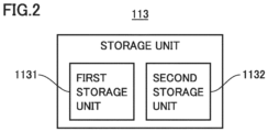
- Fig. 2 is a diagram showing a configuration of the storage unit 113 of the refrigeration cycle apparatus 100.
- the storage unit 113 includes a first storage unit 1131 and a second storage unit 1132.
- the first storage unit 1131 and the second storage unit 1132 are capable of storing the control information of the refrigeration cycle apparatus 100 independently of each other.
- the cloud server 300 transmits the above-described updates to the refrigeration cycle apparatus 100.
- control information before the update the control over the refrigeration cycle apparatus 100 using the control information before the update is also described as a “pre-update control.”
- control information before the update and the pre-update control can correspond to "first control information” and a "first control,” respectively, according to the present disclosure.
- new control information in which the control information before the update is modified will also be described as “updated control information,” and the control over the refrigeration cycle apparatus 100 using the updated control information is also described as a “post-update control.”
- the updated control information and the post-update control correspond to "second control information” and "second control,” respectively, according to the present disclosure.
- control information before the update is stored into the first storage unit 1131, and the updated control information is written to the second storage unit 1132.
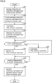
- Fig. 3 is a flowchart of one example process performed by the controller 110 of the refrigeration cycle apparatus 100.
- the refrigeration cycle apparatus 100 receives updates of the control information from the cloud server 300 (step S31), in response to which the refrigeration cycle apparatus 100 obtains updated control information from the candidate storage unit 301a of the cloud server 300 and starts writing the updated control information to the second storage unit 1132 (step S32). Note that the control information before the update stored in the first storage unit 1131 is held in the first storage unit 1131 until being deleted by a process of step S39 described below.
- the refrigeration cycle apparatus 100 continues the "pre-update control" controlling the refrigeration cycle apparatus 100 using the control information before the update (step S33). This causes the compressor 153 to continue the operation even after the writing of the updated control information is started during the operation of the compressor 153.
- the refrigeration cycle apparatus 100 determines whether the compressor 153 is caused to stop the operation through, for example, an operation stop command by the user's manual operation or an operation stop command by a timer function set by the user (step S35). If the compressor 153 continues to operate (NO in step S35), the refrigeration cycle apparatus 100 continues the pre-update control (step S36). Subsequently, the process returns to step S35.
- the refrigeration cycle apparatus 100 switches its own control mode from the "pre-update control,” in which the control information before the update is used, to the "post-update control,” in which the updated control information is used (step S37).
- the refrigeration cycle apparatus 100 determines whether the compressor 153 is caused to start the operation by the post-update control through, for example, an operation start command by the user's manual operation or an operation start command by the timer function set by the user (step S38). If the compressor 153 is not caused to start the operation by the post-update control (NO in step S38), the refrigeration cycle apparatus 100 waits for the compressor 153 to resume the operation.
- the refrigeration cycle apparatus 100 deletes the control information before the update from the first storage unit 1131 (step S39).
- Fig. 4 is a sequence diagram illustrating one example overview of a process performed by the refrigeration cycle system 1.
- the refrigeration cycle apparatus 100 in the initial state of Fig. 4 performs the "pre-update control" using the already-received control information before the update stored in the first storage unit 1131 (step S30).
- the cloud server 300 obtains updates indicative of such from the candidate storage unit 301a (step S10), and transmits the updates to the refrigeration cycle apparatus 100 (step S11).
- the refrigeration cycle apparatus 100 obtains the updates from the cloud server 300 (step S31), in response to which the refrigeration cycle apparatus 100 obtains the updated control information from the candidate storage unit 301a of the cloud server 300, and starts writing the updated control information to the second storage unit 1132 (step S32).
- the refrigeration cycle apparatus 100 continues the pre-update control using the control information before the update stored in the first storage unit 1131, until the writing of the updated control information to the second storage unit 1132 is completed (step S33).
- step S34 the refrigeration cycle apparatus 100 confirms that the compressor 153 is stopped (step S35).
- the refrigeration cycle apparatus 100 continues to perform the pre-update control until the compressor 153 is stopped for the first time after the completion of the writing of the updated control information.
- the refrigeration cycle apparatus 100 switches its control mode from the pre-update control to the "post-update control" that uses the updated control information stored in the second storage unit 1132 (step S37).
- the refrigeration cycle apparatus 100 confirms that the compressor 153 is operated by the post-update control (step S38). Once confirmed that the compressor 153 is operated by the post-update control, the refrigeration cycle apparatus 100 deletes the control information before the update from the first storage unit 1131 (step S39).
- step S39 the updated control information stored in the second storage unit 1132 is moved to the first storage unit 1131.
- This stores the already-received control information being used in the first storage unit 1131, causing no control information being stored in the second storage unit 1132.
- the control information stored in the second storage unit 1132 may be treated as the control information before the update (i.e., treating the second storage unit 1132 as the first storage unit 1131).
- the refrigeration cycle apparatus 100 includes: the refrigerant circuit 150 which includes the compressor 153; the communication device 140 which receives the control information from the cloud server 300; and the controller 110 which: includes the storage unit 113 for storing the control information received by the communication device 140; and controls the compressor 153 using the control information stored in the storage unit 113.
- the controller 110 continues the pre-update control of causing the compressor 153 to operate using the already-received control information before the update with operating experience, without forcibly stopping the operation of the compressor 153, until the completion of writing of the updated control information to the storage unit 113. Therefore, the control information can be rewritten at an appropriate time after the completion of writing of the updated control information. This allows the control information to be rewritten, without forcibly stopping the operation of the refrigeration cycle apparatus 100.
- the controller 110 continues to perform the pre-update control until the compressor 153 is caused to stop the operation for the first time after the completion of writing of the updated control information to the storage unit 113. Then, when the operation of the compressor 153 is stopped for the first time after the completion of writing of the updated control information, the controller 110 performs the post-update control of causing the compressor 153 to operate, using the updated control information, instead of using the pre-update control.
- the refrigeration cycle apparatus 100 Since the refrigeration cycle apparatus 100 switches its own mode from the pre-update control to the post-update control in such a manner while the operation of the compressor 153 is stopped, the refrigeration cycle apparatus 100 can smoothly switch its own mode from the pre-update control to the post-update control, without forcibly stopping the operation of the compressor 153.
- the controller 110 deletes the control information before the update from the storage unit 113. Stated differently, the control information before the update stored in the storage unit 113 is held, without deleting it, until the operation of the compressor 153 by the post-update control is confirmed. Therefore, if the compressor 153 is not operated by the post-update control for some reason, the compressor 153 can be readily restored to the pre-update control.
Landscapes
- Engineering & Computer Science (AREA)
- General Engineering & Computer Science (AREA)
- Mechanical Engineering (AREA)
- Physics & Mathematics (AREA)
- Chemical & Material Sciences (AREA)
- Thermal Sciences (AREA)
- Combustion & Propulsion (AREA)
- Signal Processing (AREA)
- Human Computer Interaction (AREA)
- Fuzzy Systems (AREA)
- Mathematical Physics (AREA)
- Devices That Are Associated With Refrigeration Equipment (AREA)
- Air Conditioning Control Device (AREA)
Abstract
Description
- The present disclosure relates to a refrigeration cycle apparatus.
- Refrigeration cycle apparatuses adopting a refrigeration cycle (such as air conditioners and refrigeration apparatuses) are widely used throughout the world. The information used to control the refrigeration cycle apparatus (hereinafter, also referred to as "control information") is, in general, recorded in a storage unit included in the refrigeration cycle apparatus. The storage unit is configured of a random access memory (RAM) and a read only memory (ROM), a programmable ROM (PROM) such as a flash memory, or a hard disk drive (HDD), etc.
- In recent years, the press ahead with the internet of things (IoT) puts into practice the refrigeration cycle apparatus that includes a communication device connectable to a communication network. The refrigeration cycle apparatus being connected to the communication network enables the refrigeration cycle apparatus to download from a server connected to the communication network the control information updated (upgraded) to allow better operation of the refrigeration cycle apparatus.
- For example,
Japanese Patent No. 4106941 - PTL 1:
Japanese Patent No. 4106941 - There are occasions where the outage of the refrigeration cycle apparatus is strictly not allowed. Therefore, it is desirable that the control information is rewritten, without forcibly stopping the operation of the refrigeration cycle apparatus.
Japanese Patent No. 4106941 - The present disclosure is made to solve the problem above, and an object of the present disclosure is to enable rewriting of the control information, without forcibly stopping the operation of the refrigeration cycle apparatus.
- A refrigeration cycle apparatus according to the present disclosure includes: a refrigerant circuit which includes a compressor; a communication device configured to receive control information from a server; a storage device configured to store the control information received by the communication device; and a controller configured to control the compressor, using the control information stored in the storage device. When the communication device starts receiving second control information newer than first control information stored in the storage device, the controller is configured to continue to perform a first control of causing the compressor to operate using the first control information, until writing of the second control information to the storage device is completed.
- According to the refrigeration cycle apparatus of the present disclosure, after the refrigeration cycle apparatus starts receiving the second control information, the compressor is caused to operate using the already-received first control information, without forcibly stopping the operation of the compressor, until completion of writing of the second control information to the storage device. Therefore, at an appropriate time after the completion of writing of the second control information (e.g., after the operation of the compressor is stopped by the user operation), the refrigeration cycle apparatus is allowed to rewrite the control information. As a result, the control information can be rewritten, without forcibly stopping the operation of the refrigeration cycle apparatus.
-
-
Fig. 1 is a diagram showing a configuration of a refrigeration cycle system. -
Fig. 2 is a diagram showing a configuration of a storage unit included in the refrigeration cycle apparatus. -
Fig. 3 is a flowchart of one example process performed by a controller included in the refrigeration cycle apparatus. -
Fig. 4 is a sequence diagram illustrating one example overview of a process performed by the refrigeration cycle system. - Hereinafter, embodiments according to the present disclosure will be described, with reference to the accompanying drawings. Note that the same reference signs are used to refer to the same or like parts, and the description thereof will not be repeated.
-
Fig. 1 is a diagram showing a configuration of arefrigeration cycle system 1 according to an embodiment. Therefrigeration cycle system 1 includes arefrigeration cycle apparatus 100, acommunication network 200, acloud server 300, and aremote control 400. - The
refrigeration cycle apparatus 100 includes acontroller 110, arewriting device 120, acommunication device 140, and arefrigerant circuit 150. - The
refrigerant circuit 150 is a circuit for air conditioning or refrigeration using a refrigerant and a refrigeration cycle. Therefrigerant circuit 150 includes n actuators (e.g., a pressure control valve for controlling the pressure within therefrigerant circuit 150, etc.) 151_1 through 151_n, m sensors (e.g., a temperature sensor for detecting the temperature within therefrigerant circuit 150, etc.) 152_1 through 152_m, and acompressor 153 for compressing the refrigerant. Note that therefrigerant circuit 150 may employ a well-known configuration. - The
controller 110 includes acontrol operation unit 111, aninput processing unit 112, and astorage unit 113. Theinput processing unit 112 converts signals, input from the m sensors 152_1 through 152_m, into those that can be processed by thecontrol operation unit 111, and outputs them to thecontrol operation unit 111. Based on the signals input from theinput processing unit 112, and the state amounts of the n actuators 151_1 through 151_n and thecompressor 153, thecontrol operation unit 111 controls the operation of the actuators 151_1 through 151_n and thecompressor 153. - The
storage unit 113 stores the information (hereinafter, also referred to as "control information") such as mathematical formulas, constants, and control programs that are used to control the refrigeration cycle apparatus 100 (processes by theinput processing unit 112 and the control operation unit 111). Theinput processing unit 112 and thecontrol operation unit 111 appropriately read the control information stored in thestorage unit 113, and perform processes. - The
storage unit 113 may store device information of therefrigeration cycle apparatus 100. The device information may include the model information of therefrigeration cycle apparatus 100, information of devices that are connected to therefrigeration cycle apparatus 100, the history information of operation of thecompressor 153 of therefrigeration cycle apparatus 100, etc. - While
Fig. 1 shows an example in which onestorage unit 113 is disposed inside thecontroller 110, it should be noted that the number ofstorage units 113 and the arrangement thereof are not limited thereto. For example, all or some of thestorage unit 113 may be divided into subunits and disposed external to thecontroller 110. - The
rewriting device 120 is capable of rewriting the control information stored in thestorage unit 113 of thecontroller 110. Note that the "rewriting" of the control information includes replacement of old information with new information, deletion of old information, and writing (adding) of new information. Thecommunication device 140 is connectable to thecommunication network 200. - The
remote control 400 is a device for a user of therefrigeration cycle apparatus 100 to remotely control therefrigeration cycle apparatus 100 in the space where therefrigeration cycle apparatus 100 is installed. Theremote control 400 includes adisplay device 401 and aninput device 402. - The
input device 402 of theremote control 400 is capable of receiving operation commands by the user, such as the set temperature, the operation mode, the wind direction, and the volume of the air of therefrigeration cycle apparatus 100. Theremote control 400 transmits the operation commands, input from theinput device 402, to thecontroller 110 of therefrigeration cycle apparatus 100. - The operation commands transmitted from the
remote control 400 to therefrigeration cycle apparatus 100 are reflected to thecontroller 110 controlling therefrigeration cycle apparatus 100. Theremote control 400 is also capable of showing the information received from thecontroller 110 of therefrigeration cycle apparatus 100 on thedisplay device 401. Note that, instead of or in addition to theremote control 400, smartphone having functions equivalent to those of theremote control 400 may be connectable to therefrigeration cycle apparatus 100 via thecommunication network 200. - The
cloud server 300 includes acloud storage unit 301 and acommunication device 303. Thecommunication device 303 is connectable to thecommunication network 200. Accordingly, therefrigeration cycle apparatus 100 and thecloud server 300 are capable of communications with each other via thecommunication network 200. - The
cloud storage unit 301 includes acandidate storage unit 301a. Thecandidate storage unit 301a stores information that allows rewriting of the control information stored in thestorage unit 113 of therefrigeration cycle apparatus 100. Note that the control information may be modified (upgraded) for updates by the manufacturer of therefrigeration cycle apparatus 100 or the like. Each time the control information is updated, the most-recent control information after the update is added to thecandidate storage unit 301a. When the control information is updated, information (hereinafter, also referred to as "update information") indicating that the control information is updated is also stored into thecandidate storage unit 301a. -
Fig. 2 is a diagram showing a configuration of thestorage unit 113 of therefrigeration cycle apparatus 100. Thestorage unit 113 includes afirst storage unit 1131 and asecond storage unit 1132. Thefirst storage unit 1131 and thesecond storage unit 1132 are capable of storing the control information of therefrigeration cycle apparatus 100 independently of each other. - If the control information stored in the
candidate storage unit 301a is updated, thecloud server 300 transmits the above-described updates to therefrigeration cycle apparatus 100. - In the following, already-received control information being used by the
refrigeration cycle apparatus 100 will also be described as "control information before the update," and the control over therefrigeration cycle apparatus 100 using the control information before the update is also described as a "pre-update control." The control information before the update and the pre-update control can correspond to "first control information" and a "first control," respectively, according to the present disclosure. - Moreover, in the following, new control information in which the control information before the update is modified will also be described as "updated control information," and the control over the
refrigeration cycle apparatus 100 using the updated control information is also described as a "post-update control." The updated control information and the post-update control correspond to "second control information" and "second control," respectively, according to the present disclosure. - In the following, assume that the control information before the update is stored into the
first storage unit 1131, and the updated control information is written to thesecond storage unit 1132. -
Fig. 3 is a flowchart of one example process performed by thecontroller 110 of therefrigeration cycle apparatus 100. Therefrigeration cycle apparatus 100 receives updates of the control information from the cloud server 300 (step S31), in response to which therefrigeration cycle apparatus 100 obtains updated control information from thecandidate storage unit 301a of thecloud server 300 and starts writing the updated control information to the second storage unit 1132 (step S32). Note that the control information before the update stored in thefirst storage unit 1131 is held in thefirst storage unit 1131 until being deleted by a process of step S39 described below. - Even after started writing the updated control information, the
refrigeration cycle apparatus 100 continues the "pre-update control" controlling therefrigeration cycle apparatus 100 using the control information before the update (step S33). This causes thecompressor 153 to continue the operation even after the writing of the updated control information is started during the operation of thecompressor 153. - Upon completion of the writing of the updated control information (step S34), the
refrigeration cycle apparatus 100 determines whether thecompressor 153 is caused to stop the operation through, for example, an operation stop command by the user's manual operation or an operation stop command by a timer function set by the user (step S35). If thecompressor 153 continues to operate (NO in step S35), therefrigeration cycle apparatus 100 continues the pre-update control (step S36). Subsequently, the process returns to step S35. - If the
compressor 153 is caused to stop the operation (YES in step S35), therefrigeration cycle apparatus 100 switches its own control mode from the "pre-update control," in which the control information before the update is used, to the "post-update control," in which the updated control information is used (step S37). - Subsequently, the
refrigeration cycle apparatus 100 determines whether thecompressor 153 is caused to start the operation by the post-update control through, for example, an operation start command by the user's manual operation or an operation start command by the timer function set by the user (step S38). If thecompressor 153 is not caused to start the operation by the post-update control (NO in step S38), therefrigeration cycle apparatus 100 waits for thecompressor 153 to resume the operation. - If the
compressor 153 is caused to start the operation by the post-update control (YES in step S38), therefrigeration cycle apparatus 100 deletes the control information before the update from the first storage unit 1131 (step S39). -
Fig. 4 is a sequence diagram illustrating one example overview of a process performed by therefrigeration cycle system 1. - The
refrigeration cycle apparatus 100 in the initial state ofFig. 4 performs the "pre-update control" using the already-received control information before the update stored in the first storage unit 1131 (step S30). - As the updated control information is added to the
candidate storage unit 301a, thecloud server 300 obtains updates indicative of such from thecandidate storage unit 301a (step S10), and transmits the updates to the refrigeration cycle apparatus 100 (step S11). - The
refrigeration cycle apparatus 100 obtains the updates from the cloud server 300 (step S31), in response to which therefrigeration cycle apparatus 100 obtains the updated control information from thecandidate storage unit 301a of thecloud server 300, and starts writing the updated control information to the second storage unit 1132 (step S32). - Subsequently, the
refrigeration cycle apparatus 100 continues the pre-update control using the control information before the update stored in thefirst storage unit 1131, until the writing of the updated control information to thesecond storage unit 1132 is completed (step S33). - Then, upon completion of the writing of the updated control information to the second storage unit 1132 (step S34), the
refrigeration cycle apparatus 100 confirms that thecompressor 153 is stopped (step S35). Therefrigeration cycle apparatus 100 continues to perform the pre-update control until thecompressor 153 is stopped for the first time after the completion of the writing of the updated control information. - When the
compressor 153 stops for the first time after the completion of the writing of the updated control information, therefrigeration cycle apparatus 100 switches its control mode from the pre-update control to the "post-update control" that uses the updated control information stored in the second storage unit 1132 (step S37). - Subsequently, the
refrigeration cycle apparatus 100 confirms that thecompressor 153 is operated by the post-update control (step S38). Once confirmed that thecompressor 153 is operated by the post-update control, therefrigeration cycle apparatus 100 deletes the control information before the update from the first storage unit 1131 (step S39). - While not described in
Figs. 3 and4 , after step S39, the updated control information stored in thesecond storage unit 1132 is moved to thefirst storage unit 1131. This stores the already-received control information being used in thefirst storage unit 1131, causing no control information being stored in thesecond storage unit 1132. Note that, rather than moving the updated control information from thesecond storage unit 1132 to thefirst storage unit 1131, the control information stored in thesecond storage unit 1132 may be treated as the control information before the update (i.e., treating thesecond storage unit 1132 as the first storage unit 1131). - As described above, the
refrigeration cycle apparatus 100 according to the present embodiment includes: therefrigerant circuit 150 which includes thecompressor 153; thecommunication device 140 which receives the control information from thecloud server 300; and thecontroller 110 which: includes thestorage unit 113 for storing the control information received by thecommunication device 140; and controls thecompressor 153 using the control information stored in thestorage unit 113. - If the
communication device 140 starts receiving updated control information that is newer than the control information before the update stored in thestorage unit 113, thecontroller 110 continues the pre-update control of causing thecompressor 153 to operate using the already-received control information before the update with operating experience, without forcibly stopping the operation of thecompressor 153, until the completion of writing of the updated control information to thestorage unit 113. Therefore, the control information can be rewritten at an appropriate time after the completion of writing of the updated control information. This allows the control information to be rewritten, without forcibly stopping the operation of therefrigeration cycle apparatus 100. - In particular, the
controller 110 according to the present embodiment continues to perform the pre-update control until thecompressor 153 is caused to stop the operation for the first time after the completion of writing of the updated control information to thestorage unit 113. Then, when the operation of thecompressor 153 is stopped for the first time after the completion of writing of the updated control information, thecontroller 110 performs the post-update control of causing thecompressor 153 to operate, using the updated control information, instead of using the pre-update control. Since therefrigeration cycle apparatus 100 switches its own mode from the pre-update control to the post-update control in such a manner while the operation of thecompressor 153 is stopped, therefrigeration cycle apparatus 100 can smoothly switch its own mode from the pre-update control to the post-update control, without forcibly stopping the operation of thecompressor 153. - Furthermore, after the
compressor 153 is operated for the first time by the post-update control, thecontroller 110 according to the present embodiment deletes the control information before the update from thestorage unit 113. Stated differently, the control information before the update stored in thestorage unit 113 is held, without deleting it, until the operation of thecompressor 153 by the post-update control is confirmed. Therefore, if thecompressor 153 is not operated by the post-update control for some reason, thecompressor 153 can be readily restored to the pre-update control. - The presently disclosed embodiment should be considered in all aspects as illustrative and not restrictive. The scope of the present disclosure is indicated by the appended claims, rather than by the description above, and all changes that come within the scope of the claims and the meaning and range of equivalency of the claims are intended to be embraced within their scope.
- 1 refrigeration cycle system; 100 refrigeration cycle apparatus; 110 controller; 111 control operation unit; 112 input processing unit; 113 storage unit; 120 rewriting device; 140, 303 communication device; 150 refrigerant circuit; 151 actuator; 152 sensor; 153 compressor; 200 communication network; 300 cloud server; 301 cloud storage unit; 301a candidate storage unit; 400 remote control; 401 display device; 402 input device; 1131 first storage unit; and 1132 second storage unit.
Claims (4)
- A refrigeration cycle apparatus, comprising:a refrigerant circuit which includes a compressor;a communication device configured to receive control information from a server;a storage device configured to store the control information received by the communication device; anda controller configured to control the compressor, using the control information stored in the storage device, whereinwhen the communication device starts receiving second control information newer than first control information stored in the storage device, the controller is configured to continue to perform a first control of causing the compressor to operate using the first control information, until writing of the second control information to the storage device is completed.
- The refrigeration cycle apparatus according to claim 1, wherein
the controller is configured to:continue to perform the first control, until the compressor is caused to stop operation for the first time after the writing of the second control information to the storage device is completed; andwhen the compressor is caused to stop the operation for the first time after the writing of the second control information to the storage device is completed, perform a second control of causing the compressor to operate using the second control information, instead of performing the first control. - The refrigeration cycle apparatus according to claim 2, wherein
the controller is configured to delete the first control information from the storage device after the compressor is caused to operate by the second control for the first time. - The refrigeration cycle apparatus according to any one of claims 1 to 3, wherein
the storage device has:a first storage unit configured to store the first control information; anda second storage unit to which the second control information is written.
Applications Claiming Priority (1)
| Application Number | Priority Date | Filing Date | Title |
|---|---|---|---|
| PCT/JP2020/022528 WO2021250739A1 (en) | 2020-06-08 | 2020-06-08 | Refrigeration cycle device |
Publications (2)
| Publication Number | Publication Date |
|---|---|
| EP4163571A1 true EP4163571A1 (en) | 2023-04-12 |
| EP4163571A4 EP4163571A4 (en) | 2023-07-19 |
Family
ID=78845454
Family Applications (1)
| Application Number | Title | Priority Date | Filing Date |
|---|---|---|---|
| EP20940263.5A Withdrawn EP4163571A4 (en) | 2020-06-08 | 2020-06-08 | REFRIGERATING CYCLE DEVICE |
Country Status (5)
| Country | Link |
|---|---|
| US (1) | US20230160617A1 (en) |
| EP (1) | EP4163571A4 (en) |
| JP (1) | JP7407932B2 (en) |
| CN (1) | CN115843328A (en) |
| WO (1) | WO2021250739A1 (en) |
Family Cites Families (14)
| Publication number | Priority date | Publication date | Assignee | Title |
|---|---|---|---|---|
| JP2001355951A (en) * | 2000-06-13 | 2001-12-26 | Mitsubishi Heavy Ind Ltd | Control device and system for refrigerating machine |
| JP3590891B2 (en) * | 2001-04-20 | 2004-11-17 | 株式会社日立製作所 | Service system for monitoring center and air conditioner |
| JP4106941B2 (en) | 2002-03-25 | 2008-06-25 | 三菱電機株式会社 | Air conditioning apparatus control system, remote centralized management apparatus, and control system control method |
| JP4274163B2 (en) * | 2005-09-13 | 2009-06-03 | ダイキン工業株式会社 | Air conditioning control system |
| JP4289339B2 (en) * | 2005-09-29 | 2009-07-01 | ブラザー工業株式会社 | Electric appliance setting system, image processing apparatus, and electric appliance |
| GB2564367B (en) * | 2016-06-08 | 2020-11-04 | Mitsubishi Electric Corp | Air-conditioning apparatus |
| GB2564995B (en) * | 2016-06-30 | 2021-04-28 | Mitsubishi Electric Corp | Air-conditioning apparatus |
| JP2018141616A (en) * | 2017-02-28 | 2018-09-13 | ダイキン工業株式会社 | Air conditioner |
| JP6862224B2 (en) * | 2017-03-06 | 2021-04-21 | シャープ株式会社 | Refrigerator, refrigerator control method, and program |
| CN107514848A (en) * | 2017-07-10 | 2017-12-26 | 珠海格力电器股份有限公司 | Compressor frequency adjusting method and device and frequency adjuster |
| JP7095359B2 (en) * | 2018-03-29 | 2022-07-05 | 株式会社富士通ゼネラル | Air conditioning system |
| US20210364186A1 (en) * | 2018-08-29 | 2021-11-25 | Mitsubishi Electric Corporation | Air-conditioning system and program update method of air-conditioning system |
| JP6729653B2 (en) * | 2018-09-28 | 2020-07-22 | ダイキン工業株式会社 | Air conditioning system |
| JP6699764B1 (en) * | 2019-01-16 | 2020-05-27 | 株式会社富士通ゼネラル | Air conditioning system |
-
2020
- 2020-06-08 WO PCT/JP2020/022528 patent/WO2021250739A1/en not_active Ceased
- 2020-06-08 JP JP2022530365A patent/JP7407932B2/en active Active
- 2020-06-08 EP EP20940263.5A patent/EP4163571A4/en not_active Withdrawn
- 2020-06-08 CN CN202080101560.XA patent/CN115843328A/en active Pending
- 2020-06-08 US US17/919,853 patent/US20230160617A1/en not_active Abandoned
Also Published As
| Publication number | Publication date |
|---|---|
| JPWO2021250739A1 (en) | 2021-12-16 |
| US20230160617A1 (en) | 2023-05-25 |
| EP4163571A4 (en) | 2023-07-19 |
| JP7407932B2 (en) | 2024-01-04 |
| CN115843328A (en) | 2023-03-24 |
| WO2021250739A1 (en) | 2021-12-16 |
Similar Documents
| Publication | Publication Date | Title |
|---|---|---|
| US10620942B2 (en) | Method for adapting firmware of a wireless communication device | |
| CN111562933A (en) | Air conditioner upgrading method and air conditioner system | |
| US10241807B2 (en) | Vehicle control device, reprogramming system | |
| CN104168327A (en) | Method for automatically updating external device | |
| US20210364186A1 (en) | Air-conditioning system and program update method of air-conditioning system | |
| CN104598276A (en) | Online upgrade method and online upgrade device for touch screen firmware | |
| CN112527370A (en) | Method for remotely and differentially upgrading Internet of things equipment | |
| EP4163571A1 (en) | Refrigeration cycle device | |
| US11828479B2 (en) | Server based air conditioning system adaptor for updating control program | |
| CN106406903A (en) | System updating method and apparatus for equipment | |
| US20150119999A1 (en) | Communication Apparatus, Communication System and Communication Method | |
| KR102434126B1 (en) | Apparatus for processing programmable logic controller program | |
| CN114322244A (en) | Program upgrading method and device and multi-split air conditioning system | |
| CN104090802A (en) | Protection method for network camera power failure | |
| KR20220086248A (en) | Method and apparatus for management control of vehicle ota update | |
| CN112346770A (en) | Embedded program online updating method | |
| JP7341329B2 (en) | Refrigeration cycle system and refrigeration cycle equipment | |
| CN108965026B (en) | Equipment upgrading method, unit system and unit upgrading system | |
| US10935935B2 (en) | Safety control unit, safety control method, and safety control program | |
| JPWO2012077604A1 (en) | Processing apparatus, program update method, and program | |
| JP7825467B2 (en) | Switch device and switch system | |
| US20190187669A1 (en) | Control unit, data refresh method, and data refresh program | |
| CN116964555A (en) | Methods for creating update data, methods for overwriting firmware, methods for updating firmware, and electronic devices for executing the methods | |
| JPH0798659A (en) | Down load bootstrap method | |
| JP2000283529A (en) | Centralized control system for air conditioners |
Legal Events
| Date | Code | Title | Description |
|---|---|---|---|
| STAA | Information on the status of an ep patent application or granted ep patent |
Free format text: STATUS: THE INTERNATIONAL PUBLICATION HAS BEEN MADE |
|
| PUAI | Public reference made under article 153(3) epc to a published international application that has entered the european phase |
Free format text: ORIGINAL CODE: 0009012 |
|
| STAA | Information on the status of an ep patent application or granted ep patent |
Free format text: STATUS: REQUEST FOR EXAMINATION WAS MADE |
|
| 17P | Request for examination filed |
Effective date: 20221201 |
|
| AK | Designated contracting states |
Kind code of ref document: A1 Designated state(s): AL AT BE BG CH CY CZ DE DK EE ES FI FR GB GR HR HU IE IS IT LI LT LU LV MC MK MT NL NO PL PT RO RS SE SI SK SM TR |
|
| A4 | Supplementary search report drawn up and despatched |
Effective date: 20230619 |
|
| RIC1 | Information provided on ipc code assigned before grant |
Ipc: F25B 49/02 20060101ALI20230613BHEP Ipc: F24F 11/63 20180101ALI20230613BHEP Ipc: F24F 11/86 20180101ALI20230613BHEP Ipc: F25B 1/00 20060101AFI20230613BHEP |
|
| DAV | Request for validation of the european patent (deleted) | ||
| DAX | Request for extension of the european patent (deleted) | ||
| STAA | Information on the status of an ep patent application or granted ep patent |
Free format text: STATUS: THE APPLICATION HAS BEEN WITHDRAWN |
|
| 18W | Application withdrawn |
Effective date: 20240902 |