EP4163554B1 - Regulation system for a thermo-hydraulic circuit and control method - Google Patents
Regulation system for a thermo-hydraulic circuit and control method Download PDFInfo
- Publication number
- EP4163554B1 EP4163554B1 EP22200182.8A EP22200182A EP4163554B1 EP 4163554 B1 EP4163554 B1 EP 4163554B1 EP 22200182 A EP22200182 A EP 22200182A EP 4163554 B1 EP4163554 B1 EP 4163554B1
- Authority
- EP
- European Patent Office
- Prior art keywords
- carrier fluid
- flow rate
- valve
- temperature
- mass
- Prior art date
- Legal status (The legal status is an assumption and is not a legal conclusion. Google has not performed a legal analysis and makes no representation as to the accuracy of the status listed.)
- Active
Links
Images

Classifications
-
- G—PHYSICS
- G05—CONTROLLING; REGULATING
- G05D—SYSTEMS FOR CONTROLLING OR REGULATING NON-ELECTRIC VARIABLES
- G05D23/00—Control of temperature
- G05D23/19—Control of temperature characterised by the use of electric means
- G05D23/1927—Control of temperature characterised by the use of electric means using a plurality of sensors
- G05D23/193—Control of temperature characterised by the use of electric means using a plurality of sensors sensing the temperaure in different places in thermal relationship with one or more spaces
- G05D23/1931—Control of temperature characterised by the use of electric means using a plurality of sensors sensing the temperaure in different places in thermal relationship with one or more spaces to control the temperature of one space
-
- F—MECHANICAL ENGINEERING; LIGHTING; HEATING; WEAPONS; BLASTING
- F24—HEATING; RANGES; VENTILATING
- F24D—DOMESTIC- OR SPACE-HEATING SYSTEMS, e.g. CENTRAL HEATING SYSTEMS; DOMESTIC HOT-WATER SUPPLY SYSTEMS; ELEMENTS OR COMPONENTS THEREFOR
- F24D19/00—Details
- F24D19/10—Arrangement or mounting of control or safety devices
- F24D19/1006—Arrangement or mounting of control or safety devices for water heating systems
- F24D19/1051—Arrangement or mounting of control or safety devices for water heating systems for domestic hot water
-
- F—MECHANICAL ENGINEERING; LIGHTING; HEATING; WEAPONS; BLASTING
- F24—HEATING; RANGES; VENTILATING
- F24D—DOMESTIC- OR SPACE-HEATING SYSTEMS, e.g. CENTRAL HEATING SYSTEMS; DOMESTIC HOT-WATER SUPPLY SYSTEMS; ELEMENTS OR COMPONENTS THEREFOR
- F24D19/00—Details
- F24D19/10—Arrangement or mounting of control or safety devices
- F24D19/1006—Arrangement or mounting of control or safety devices for water heating systems
- F24D19/1009—Arrangement or mounting of control or safety devices for water heating systems for central heating
- F24D19/1012—Arrangement or mounting of control or safety devices for water heating systems for central heating by regulating the speed of a pump
-
- F—MECHANICAL ENGINEERING; LIGHTING; HEATING; WEAPONS; BLASTING
- F24—HEATING; RANGES; VENTILATING
- F24D—DOMESTIC- OR SPACE-HEATING SYSTEMS, e.g. CENTRAL HEATING SYSTEMS; DOMESTIC HOT-WATER SUPPLY SYSTEMS; ELEMENTS OR COMPONENTS THEREFOR
- F24D19/00—Details
- F24D19/10—Arrangement or mounting of control or safety devices
- F24D19/1006—Arrangement or mounting of control or safety devices for water heating systems
- F24D19/1009—Arrangement or mounting of control or safety devices for water heating systems for central heating
- F24D19/1015—Arrangement or mounting of control or safety devices for water heating systems for central heating using a valve or valves
- F24D19/1024—Arrangement or mounting of control or safety devices for water heating systems for central heating using a valve or valves a multiple way valve
-
- F—MECHANICAL ENGINEERING; LIGHTING; HEATING; WEAPONS; BLASTING
- F24—HEATING; RANGES; VENTILATING
- F24D—DOMESTIC- OR SPACE-HEATING SYSTEMS, e.g. CENTRAL HEATING SYSTEMS; DOMESTIC HOT-WATER SUPPLY SYSTEMS; ELEMENTS OR COMPONENTS THEREFOR
- F24D19/00—Details
- F24D19/10—Arrangement or mounting of control or safety devices
- F24D19/1006—Arrangement or mounting of control or safety devices for water heating systems
- F24D19/1009—Arrangement or mounting of control or safety devices for water heating systems for central heating
- F24D19/1039—Arrangement or mounting of control or safety devices for water heating systems for central heating the system uses a heat pump
-
- F—MECHANICAL ENGINEERING; LIGHTING; HEATING; WEAPONS; BLASTING
- F24—HEATING; RANGES; VENTILATING
- F24D—DOMESTIC- OR SPACE-HEATING SYSTEMS, e.g. CENTRAL HEATING SYSTEMS; DOMESTIC HOT-WATER SUPPLY SYSTEMS; ELEMENTS OR COMPONENTS THEREFOR
- F24D19/00—Details
- F24D19/10—Arrangement or mounting of control or safety devices
- F24D19/1006—Arrangement or mounting of control or safety devices for water heating systems
- F24D19/1051—Arrangement or mounting of control or safety devices for water heating systems for domestic hot water
- F24D19/1054—Arrangement or mounting of control or safety devices for water heating systems for domestic hot water the system uses a heat pump
-
- F—MECHANICAL ENGINEERING; LIGHTING; HEATING; WEAPONS; BLASTING
- F24—HEATING; RANGES; VENTILATING
- F24F—AIR-CONDITIONING; AIR-HUMIDIFICATION; VENTILATION; USE OF AIR CURRENTS FOR SCREENING
- F24F11/00—Control or safety arrangements
- F24F11/62—Control or safety arrangements characterised by the type of control or by internal processing, e.g. using fuzzy logic, adaptive control or estimation of values
- F24F11/63—Electronic processing
-
- F—MECHANICAL ENGINEERING; LIGHTING; HEATING; WEAPONS; BLASTING
- F24—HEATING; RANGES; VENTILATING
- F24D—DOMESTIC- OR SPACE-HEATING SYSTEMS, e.g. CENTRAL HEATING SYSTEMS; DOMESTIC HOT-WATER SUPPLY SYSTEMS; ELEMENTS OR COMPONENTS THEREFOR
- F24D2200/00—Heat sources or energy sources
- F24D2200/04—Gas or oil fired boiler
-
- F—MECHANICAL ENGINEERING; LIGHTING; HEATING; WEAPONS; BLASTING
- F24—HEATING; RANGES; VENTILATING
- F24D—DOMESTIC- OR SPACE-HEATING SYSTEMS, e.g. CENTRAL HEATING SYSTEMS; DOMESTIC HOT-WATER SUPPLY SYSTEMS; ELEMENTS OR COMPONENTS THEREFOR
- F24D2200/00—Heat sources or energy sources
- F24D2200/12—Heat pump
-
- F—MECHANICAL ENGINEERING; LIGHTING; HEATING; WEAPONS; BLASTING
- F24—HEATING; RANGES; VENTILATING
- F24D—DOMESTIC- OR SPACE-HEATING SYSTEMS, e.g. CENTRAL HEATING SYSTEMS; DOMESTIC HOT-WATER SUPPLY SYSTEMS; ELEMENTS OR COMPONENTS THEREFOR
- F24D2220/00—Components of central heating installations excluding heat sources
- F24D2220/02—Fluid distribution means
- F24D2220/0207—Pumps
-
- F—MECHANICAL ENGINEERING; LIGHTING; HEATING; WEAPONS; BLASTING
- F24—HEATING; RANGES; VENTILATING
- F24D—DOMESTIC- OR SPACE-HEATING SYSTEMS, e.g. CENTRAL HEATING SYSTEMS; DOMESTIC HOT-WATER SUPPLY SYSTEMS; ELEMENTS OR COMPONENTS THEREFOR
- F24D2220/00—Components of central heating installations excluding heat sources
- F24D2220/04—Sensors
- F24D2220/042—Temperature sensors
-
- F—MECHANICAL ENGINEERING; LIGHTING; HEATING; WEAPONS; BLASTING
- F24—HEATING; RANGES; VENTILATING
- F24D—DOMESTIC- OR SPACE-HEATING SYSTEMS, e.g. CENTRAL HEATING SYSTEMS; DOMESTIC HOT-WATER SUPPLY SYSTEMS; ELEMENTS OR COMPONENTS THEREFOR
- F24D2220/00—Components of central heating installations excluding heat sources
- F24D2220/04—Sensors
- F24D2220/044—Flow sensors
Definitions
- the present invention relates to the field of systems for controlling temperatures and mass or volumetric flow rates inside (thermal) energy distribution systems.
- the invention relates to a regulation system for a thermo-hydraulic circuit configured to jointly control the temperature and mass or volumetric flow rate in a thermal energy distribution system, such as for example, but not exclusively, heating and cooling systems used in residential buildings or in industrial plants for the distribution of energy from a thermal machine (or from a thermal energy storage) to the radiator or between heat pump and one or more thermal energy storages.
- a thermal energy distribution system such as for example, but not exclusively, heating and cooling systems used in residential buildings or in industrial plants for the distribution of energy from a thermal machine (or from a thermal energy storage) to the radiator or between heat pump and one or more thermal energy storages.
- the current automated management technologies allows implementing highly efficient temperature control systems or can be associated with pre-existing thermoregulation systems to optimize the performance thereof.
- thermoregulation systems for thermo-hydraulic circuits are generally managed so as to ensure a desired temperature in one or more volumes to be heated or cooled, e.g., the temperature of the air in the case of one or more residential units of a building and/or in individual rooms thereof, or the temperature of a carrier fluid inside a chamber or duct at a given point to be controlled, e.g., at the inlet of one or more industrial machines.
- the systems controlling the opening or closing of a three-way valve within such regulating systems suitably mix the delivery carrier fluid of the plant with the return carrier fluid.
- thermoregulation control systems do not allow adequately managing the quick achievement of the desired optimal temperature.
- control systems of the prior art require several iterative cycles to reach the optimal operation of the plant as a function of the available control parameters (typically, the opening/closing of the three-way valve alone).
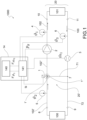
- reference numeral 1000 indicates a regulation system for a thermo-hydraulic circuit as a whole, i.e., a system for controlling the temperature of a fluid in a volume intended to be heated or cooled.
- the regulation system for a thermo-hydraulic circuit is a heating system or a cooling system or an air conditioning system for a building comprising the thermo-hydraulic circuit, where the volume intended to be heated or cooled is, for example, the volume of air of a room of the building or of the whole building, or is a volume of fluid inside heat exchange terminals or radiators.
- the regulation system 1000 for a thermo-hydraulic circuit comprises a thermo-hydraulic circuit 20 and an electronic control unit 14.
- the thermo-hydraulic circuit 20 comprises a thermal machine 100, e.g., a heat generator (a boiler or a heat pump or a heat exchanger or the like) or a heat absorber (an air conditioner or the like), adapted to heat or cool a carrier fluid.
- the thermo-hydraulic circuit 20 comprises at least one heat exchange terminal 101.
- Heat exchange terminal means any thermal machine or thermo-hydraulic configuration adapted to exchange heat with a thermal load, e.g., a radiant terminal, one or more radiators, convectors, fan heaters, floor or ceiling radiant panels or radiant tube bundles or the like, or one or more heat exchangers, or one or more thermal storages, or one or more hydraulic separators upstream of one or more radiant terminals, or a combination thereof.
- a thermal load e.g., a radiant terminal, one or more radiators, convectors, fan heaters, floor or ceiling radiant panels or radiant tube bundles or the like, or one or more heat exchangers, or one or more thermal storages, or one or more hydraulic separators upstream of one or more radiant terminals, or a combination thereof.
- the thermo-hydraulic circuit 20 further comprises a carrier fluid circulation system 20' adapted to allow the circulation of a carrier fluid inside the thermo-hydraulic circuit 20.
- the carrier fluid circulation system 20' includes a delivery duct 102 for transferring the carrier fluid from the thermal machine 100 to the heat exchange terminal 101, and a return duct 103 for transferring the carrier fluid from the heat exchange terminal 101 towards the thermal machine 100.
- a three-way valve 1 is arranged along the delivery duct 102 and is fluidically connected to the thermal machine 100 and the return duct 103.
- the three-way valve 1 is operable to mix the carrier fluid in the delivery duct 102 with the carrier fluid in the return duct 103.
- the delivery duct 102 allows the carrier fluid to flow from the thermal machine 100 to the radiant element 101, and possibly to other elements (not shown) of the thermo-hydraulic circuit 20, such as a boiler/tank for domestic hot water, for example.
- the return duct 103 allows a carrier fluid flow from the radiant element 101 to return towards the thermal machine 100 and towards the three-way valve 1.
- a pump 2 is installed on the delivery duct 102 and is adapted to pump the carrier fluid through the carrier fluid circulation system.
- the pump 2 is installed on the return duct 103 upstream of the three-way valve 1, i.e., before the three-way valve 1 and downstream of the radiant element 101, in the circulating direction of the carrier fluid (diagrammatically indicated by the arrows in Figure 1 ).
- the three-way valve 1 is arranged on the delivery duct 102 between the thermal machine 100 and the pump 2, along the delivery duct 102.
- the three-way valve 1 can thus be activated to mix the carrier fluid from a thermal machine outlet 8 of the thermal machine 100 (e.g., a "hot” carrier fluid of the thermal machine) with the "cold" carrier fluid from a radiator outlet 11 of the heat exchange terminal 101 so as to regulate - in particular, to lower in the case of "hot” fluid from the thermal machine or to heat in the case of "cold” fluid from the thermal machine - the temperature of the carrier fluid in the delivery duct 102 leaving the three-way valve 1.
- a thermal machine outlet 8 of the thermal machine 100 e.g., a "hot” carrier fluid of the thermal machine
- radiator outlet 11 of the heat exchange terminal 101 so as to regulate - in particular, to lower in the case of "hot” fluid from the thermal machine or to heat in the case of "cold” fluid from the thermal machine - the temperature of the carrier fluid in the delivery
- the delivery duct 102 comprises a first duct portion 102' connecting the thermal machine outlet 8 to a first inlet 1' of the three-way valve and in which carrier fluid directly from the thermal machine 100 circulates.
- the delivery duct 102 also comprises a second duct portion 102" which is directly connected to a valve outlet of the three-way valve 1 and in which a mixed carrier fluid circulates, i.e., a carrier fluid obtained by mixing the carrier fluid directly from the thermal machine 100 with the carrier fluid from the heat exchange terminal 101, in particular from the radiator outlet 11 of the heat exchange terminal.
- the thermo-hydraulic circuit 20 comprises at least a first temperature sensor 4 installed on the delivery duct 102 downstream of the three-way valve 1, i.e., preferably on the second duct portion 102", and even more preferably downstream of pump 2.
- the first temperature sensor 4 is adapted to measure the post-valve delivery temperature ⁇ 1 of the carrier fluid downstream of the three-way valve 1 in the flowing direction of the carrier fluid.
- the thermo-hydraulic circuit 20 also comprises at least a second temperature sensor 5 installed on the delivery duct 102 or inside the thermal machine 100, upstream of the three-way valve 1, i.e., preferably on the first duct portion 102'.
- the second temperature sensor 5 is adapted to measure the pre-valve delivery temperature ⁇ 2 of the carrier fluid upstream of the three-way valve 1 in the flowing direction of the carrier fluid.
- the thermo-hydraulic circuit 20 further comprises at least a third temperature sensor 6 installed on the return duct 103 or inside the heat exchange terminal 101 and adapted to measure the temperature ⁇ 3 of the carrier fluid downstream of the heat exchange terminal 101 in the flowing direction of the carrier fluid.
- a third temperature sensor 6 is further installed upstream of the three-way valve 1.
- At least one flow or flow rate sensor 3 is installed in the fluid circulation system to measure a mass or volumetric flow rate ⁇ 1 of the carrier fluid in an area of the fluid circulation system 20'.
- the flow or flow rate sensor 3 is installed on the return duct 103, even more preferably is installed downstream of the heat exchange terminal 101 and upstream of a second inlet 1" of the three-way valve 1.
- the flow or flow rate sensor 3 is installed before a point 7 of bifurcation of the return duct 103 into two duct branches 71, 72, where a first branch 71 of said two branches 71, 72 is connected to the second inlet 1" of the three-way valve 1 and the second branch 72 of said two branches is connected to the thermal machine 100, and in particular to the machine inlet 9 of the thermal machine 100.
- the electronic control unit 14 is operatively connected to the three-way valve 1, the pump 2, the first temperature sensor 4, the second temperature sensor 5, the third temperature sensor 6, and the flow or flow rate sensor 3, to read parameters or control the activation thereof.
- the electronic control unit 14 is configured to acquire the post-valve delivery temperature ⁇ 1 , the pre-valve delivery temperature ⁇ 2 , the carrier fluid temperature ⁇ 3 downstream of the heat exchange terminal 101, the value of mass or volumetric flow rate ⁇ 1 of the carrier fluid, from the respective sensor.
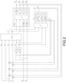
- the electronic control unit 14 comprises a storage device 140 in which a model function V ⁇ of the operation of the valve connected to the thermo-hydraulic circuit 20 is stored, and a processing unit 141 configured to calculate the values of certain signals described below and which will be better understood with reference to Figure 2 showing an example of a control diagram uploaded in the processing unit 141.
- the processing unit 141 is configured to calculate a valve control signal u adapted to determine an opening value of the three-way valve 1 for mixing the carrier fluid from the thermal machine 100 and from the heat exchange terminal 101 as a function of (i.e., according to a processing of) said opening value of the three-way valve 1.
- the processing unit 141 is configured to calculate a pump control signal p g adapted to regulate the value of power delivered by the pump, i.e., the mass or volumetric flow rate of the carrier fluid flow.
- the processing unit 141 is further configured to calculate an estimated post-valve delivery temperature value ⁇ 1 ⁇ and an estimated mass flow rate value m ⁇ 1 ⁇ as output values of the model function V ⁇ of the thermo-hydraulic circuit 20.
- the processing unit 141 is further configured to jointly calculate the estimated post-valve delivery temperature value and an estimated mass flow rate value m ⁇ 1 ⁇ as output values of the model function V ⁇ , i.e., in the same calculating iteration.
- Such a processing unit 141 is further configured to calculate a carrier fluid delivery temperature error e ⁇ 1 and a carrier fluid mass or volumetric flow rate error e ⁇ 1 .
- a carrier fluid delivery temperature error e ⁇ 1 is calculated by the processing unit 141 as a function of (e.g., by means of an algebraic sum) a desired post-valve delivery temperature value r ⁇ 1 , the measured post-valve delivery temperature ⁇ 1 and the estimated post-valve delivery temperature value ⁇ 1 ⁇ .
- such a carrier fluid mass or volumetric flow rate error e ⁇ 1 is calculated by the processing unit 141 as a function of a desired mass or volumetric flow rate value r ⁇ 1 , the value of measured mass or volumetric flow rate ⁇ 1 of the carrier fluid and the estimated mass or volumetric flow rate value m ⁇ 1 ⁇ .
- valve control signal u and the pump control signal p g are calculated as a function of the mass flow rate error e ⁇ 1 and the carrier fluid delivery temperature error e ⁇ 1 .
- the model function V ⁇ consists of a family of similar transformations combined with one another by a fuzzy system of the Takagi-Sugeno type.
- valve control signal u and the pump control signal p g are also calculated as a function of the desired mass or volumetric flow rate value r ⁇ 1 , the desired post-valve delivery temperature value r ⁇ 1 , the value of the pre-valve delivery temperature ⁇ 2 , the temperature ⁇ 3 of the carrier fluid downstream of the heat exchange terminal 101.
- the pre-valve delivery temperature ⁇ 2 and the temperature ⁇ 3 of the carrier fluid downstream of the heat exchange terminal 101 are suitably delayed over time by a respective delay line D 2 , D 3 , (e.g., a transfer function which delays the pre-valve delivery signal ⁇ 2 and the temperature ⁇ 3 of the carrier fluid) to obtain a delayed pre-valve delivery temperature ⁇ 5 and a delayed temperature ⁇ 6 of carrier fluid downstream of the heat exchange terminal 101.
- a respective delay line D 2 , D 3 e.g., a transfer function which delays the pre-valve delivery signal ⁇ 2 and the temperature ⁇ 3 of the carrier fluid
- the estimated post-valve delivery temperature value ⁇ 1 ⁇ is calculated through a third delay line (e.g., a transfer function which delays the signal) from a first post-valve delivery temperature value ⁇ 4 ⁇ output by the model function V ⁇ and the estimated mass flow rate value m ⁇ 1 ⁇ is calculated by adding a second predefined time delay to a first mass flow rate value m ⁇ 4 ⁇ output by the model function V ⁇ .
- a third delay line e.g., a transfer function which delays the signal
- the delayed pre-valve delivery temperature ⁇ 5 , the delayed temperature ⁇ 6 of carrier fluid downstream of the heat exchange terminal 101 are calculated as a function of the delayed valve control signal u according to a predetermined delay range and the delayed control signal p g to pump 2 according to a second predetermined delay range.
- the delayed pre-valve delivery temperature ⁇ 5 , the delayed temperature ⁇ 6 of carrier fluid downstream of the heat exchange terminal 101 and the estimated post-valve delivery temperature ⁇ 1 ⁇ are calculated through auxiliary delay lines which process the value of mass or volumetric flow rate signals m ⁇ 5 ⁇ , m ⁇ 6 ⁇ and m ⁇ 4 ⁇ estimated by the model function V ⁇ , respectively, which in turn calculates them by processing the value of the control signal u to valve 1 and the value of the control signal p g to pump 2.
- thermo-hydraulic circuit the processing logic executed in the electronic control unit 14 for controlling the regulation system 1000 for a thermo-hydraulic circuit will be described in greater detail below.
- the block P ( z ) is the actual plant, schematized in Figure 1 , and which is reached by the valve control signal u and the pump control signal p g .
- the block V ⁇ is the model (or observer) function which allows estimating values of a status of not directly observable parameters.
- the model function V ⁇ together with the special delay blocks indicated on the right in Figure 2 (D 1 , z -dm ) are a predictor which models the actual plant P ( z ).
- the block indicated by ⁇ ( z ) is the controller, i.e., the series of code instructions executed by the processing unit 141 to calculate the valve control signal u and the pump control signal p g .
- the further blocks D 1 , D 2 and D 3 instead are particular delay lines provided with two inlets, one for the quantity to be delayed, the other for a quantity of the volumetric or mass flow rate type, employed in order to obtain a delay depending on the values taken by the latter in past instants.
- the value of the quantity output from the particular delay line ( ⁇ 1 ⁇ , ⁇ 5 or ⁇ 6 ) is calculated by linearly interpolating the last two elements of a circular queue containing pairs of values representing the value taken by the quantity at the input of the particular delay line ( ⁇ 1 ⁇ , ⁇ 2 or ⁇ 3 ) in past instants and the current position of each of these values within the delay line.
- the positions are iteratively updated in a proportional manner to the fluid flow rate ( m ⁇ 4 ⁇ , m ⁇ 5 ⁇ or m ⁇ 6 ⁇ ) and the integration step.
- model function V ⁇ is shown in Figure 3 , for example.
- the model of the plant can be obtained through a Takagi-Sugeno model V of the system.
- the transfer matrixes P ⁇ 1 ( u , p g ), P ⁇ 2 ( u,p g ) , P ⁇ 3 ( u , p g ) and the known terms b ⁇ ( u , p g ), ⁇ ( u , p g ) are obtained as a convex combination of a certain number of similar models with constant coefficients, where the combiners are the membership functions of the variables u and p g in a suitable two-dimensional grid of fuzzy sets.
- the quantities ⁇ 4 ⁇ and m ⁇ 4 ⁇ are calculated as a convex combination of the images of the quantities p g , u, ⁇ 5 and ⁇ 6 through a certain number of similar transformations where the combiner coefficients are the membership functions of the variables p g and u in a two-dimensional grid of fuzzy sets.
- the quantities m ⁇ 5 ⁇ and m ⁇ 6 ⁇ are calculated as a convex combination of the images of the quantities p g , u through the same number of similar transformations, where the combiners are the same membership functions the variables p g and u in the two-dimensional grid of fuzzy sets.
- controller with ⁇ ( z ) is shown in Figure 4 .
- the variables u and p g are the algebraic sum of an open chain component, calculated by the block V ⁇ -1 , and of a closed chain, calculated by the block K (z).
- the function of the open chain component ⁇ ( z ) of the controller is that of obtaining a particular inverse of the model function V ⁇ which exactly returns those values of the control variables u FF and p gFF which, together with the current values of ⁇ 5 and ⁇ 6 , are mapped by the model function right in the values of the references r ⁇ 1 and r ⁇ 1 given at the input of block V ⁇ -1 together with the values ⁇ 5 and ⁇ 6 .
- such a block can be implemented by employing the generalized Newton-Raphson method for the multi-variable case.
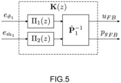
- the feedback component ⁇ ( z ) of the controller is shown in Figure 5 .
- the function of this component K ( z ) is that of increasing, by taking advantage of the effect of the feedback connection, the disturbance rejection of the closed chain system and attenuating the effects of the residual modelling error in the long term.
- the design of the feedback block can occur with various state-of-the-art techniques, but in an advantageous embodiment, this component is obtained using two controllers with one input and one output of proportional, integral and derivative type, one for the control chain related to the temperature ( ⁇ 1 (z)), the other for that related to the volumetric or mass flow rate ( ⁇ 2 (z)), connected in series to a decoupler element P 1 -1 which can be the inverse Jacobian matrix of the model function calculated at point u FF , p gFF , ⁇ 5 and ⁇ 6 .
- the correct determination of the characteristic length of the special delay lines D 1 , D 2 and D 3 is equally important. These parameters can be determined with identification methods known at the state of the art, but even better they can be determined based to the onsite measurement of the distance travelled by the fluid between the body of valve 1 and the temperature sensors 4, 5, 6, respectively.
- thermo-hydraulic circuit 1000 of the present invention advantageously allows controlling the three-way valve and the pump in a coupled manner to obtain a more timely, adequate and efficient response for the desired temperature set point in the considered volume of fluid.
- a control such as to act simultaneously on the valve and the pump to change the value of the flow rate alone or of the temperature alone. This is particularly distinctive with respect to the systems of the prior art which do not include controlling both the valve and the pump.
- the system described can provide the accurate tracking of preprogrammed trajectories (i.e., known in the future in terms of temperature and volumetric or mass flow rate). This specific quality also makes the invention very useful within the context of controlling industrial processes where simultaneously controlling temperature and flow rate of an energy carrier fluid is required.
Landscapes
- Engineering & Computer Science (AREA)
- Physics & Mathematics (AREA)
- Combustion & Propulsion (AREA)
- General Engineering & Computer Science (AREA)
- Mechanical Engineering (AREA)
- Chemical & Material Sciences (AREA)
- Thermal Sciences (AREA)
- Signal Processing (AREA)
- Remote Sensing (AREA)
- General Physics & Mathematics (AREA)
- Automation & Control Theory (AREA)
- Mathematical Physics (AREA)
- Fuzzy Systems (AREA)
- Control Of Temperature (AREA)
- Fluid-Pressure Circuits (AREA)
Applications Claiming Priority (1)
| Application Number | Priority Date | Filing Date | Title |
|---|---|---|---|
| IT102021000025670A IT202100025670A1 (it) | 2021-10-07 | 2021-10-07 | Sistema di regolazione per un circuito termoidraulico e metodo di controllo |
Publications (3)
| Publication Number | Publication Date |
|---|---|
| EP4163554A1 EP4163554A1 (en) | 2023-04-12 |
| EP4163554B1 true EP4163554B1 (en) | 2024-09-18 |
| EP4163554C0 EP4163554C0 (en) | 2024-09-18 |
Family
ID=79018913
Family Applications (1)
| Application Number | Title | Priority Date | Filing Date |
|---|---|---|---|
| EP22200182.8A Active EP4163554B1 (en) | 2021-10-07 | 2022-10-07 | Regulation system for a thermo-hydraulic circuit and control method |
Country Status (5)
| Country | Link |
|---|---|
| US (1) | US12140977B2 (pl) |
| EP (1) | EP4163554B1 (pl) |
| ES (1) | ES2994229T3 (pl) |
| IT (1) | IT202100025670A1 (pl) |
| PL (1) | PL4163554T3 (pl) |
Families Citing this family (2)
| Publication number | Priority date | Publication date | Assignee | Title |
|---|---|---|---|---|
| CN117704466A (zh) * | 2023-11-30 | 2024-03-15 | 艾沃(深圳)智能环境科技有限公司 | 一种温度调控方法 |
| CN121939644B (zh) * | 2026-03-31 | 2026-06-09 | 长沙麦融高科股份有限公司 | 一种热管冷却双回路系统的状态感知无扰切换控制方法 |
Family Cites Families (18)
| Publication number | Priority date | Publication date | Assignee | Title |
|---|---|---|---|---|
| CH510237A (de) * | 1968-06-15 | 1971-07-15 | Troesch Hans A Dr Ing | Verfahren zum Regeln von Heizungsanlagen und Heizungsanlage zur Ausführung des Verfahrens |
| DE2940790C1 (de) * | 1979-10-09 | 1982-03-18 | Fa. Rud. Otto Meyer, 2000 Hamburg | Verfahren zur energiesparenden Temperaturregelung von Waermeversorgungsanlagen |
| JP3918786B2 (ja) * | 2003-07-30 | 2007-05-23 | 株式会社デンソー | 貯湯式ヒートポンプ給湯装置 |
| NL1032598C2 (nl) * | 2006-09-29 | 2009-02-25 | Kamstrup B V | Inrichting, systeem en werkwijze voor het besturen van een verwarmingssysteem. |
| KR100812937B1 (ko) * | 2007-05-10 | 2008-03-11 | 주식회사 경동나비엔 | 온수 공급 시스템 |
| KR101018774B1 (ko) * | 2008-06-24 | 2011-03-07 | 주식회사 경동네트웍 | 온수 온도를 일정하게 유지시키기 위한 온수 공급 시스템 |
| WO2011129248A1 (ja) * | 2010-04-15 | 2011-10-20 | 三菱電機株式会社 | 給湯システム制御装置及び給湯システム制御プログラム及び給湯システム運転方法 |
| DK2874039T3 (en) * | 2013-11-19 | 2017-07-17 | Grundfos Holding As | Method of controlling a heat transfer system as well as such a heat transfer system |
| GB2520978A (en) * | 2013-12-05 | 2015-06-10 | Zonealone Ltd | A domestic hot water installation |
| DE102015014378A1 (de) * | 2015-11-09 | 2017-05-11 | Wilo Se | Verfahren zur Regelung einer Kreiselpumpe sowie zugehöriges Pumpensystem |
| US11221150B2 (en) * | 2016-05-13 | 2022-01-11 | Lochinvar, Llc | System and method of controlling a mixing valve of a heating system |
| GB2568910B (en) * | 2017-11-30 | 2021-09-15 | Minibems Ltd | Control method and device for a heating system or cooling system |
| EP3525060B1 (en) * | 2018-02-08 | 2021-04-21 | Grundfos Holding A/S | Flow control module and method for controlling the flow in a hydronic system |
| US11754296B2 (en) | 2018-09-28 | 2023-09-12 | Alperia Green Future S.R.L. | System and method for controlling a fluid vector temperature in order to heat a building |
| US10852008B2 (en) * | 2018-12-20 | 2020-12-01 | Aerco International, Inc. | Water heater with mix tank fluid time delay for causal feedforward control of hot water temperature |
| IT201900012927A1 (it) * | 2019-07-25 | 2021-01-25 | Fimcim Spa | Processo ed apparecchiatura di monitoraggio e/o controllo di un impianto di condizionamento e/o riscaldamento |
| US11846433B2 (en) * | 2019-09-27 | 2023-12-19 | Rheem Manufacturing Company | Heated water recirculation control |
| CN116917671B (zh) * | 2021-01-12 | 2026-01-23 | 阿里斯顿公司 | 用于控制锅炉的方法以及锅炉 |
-
2021
- 2021-10-07 IT IT102021000025670A patent/IT202100025670A1/it unknown
-
2022
- 2022-10-06 US US17/961,184 patent/US12140977B2/en active Active
- 2022-10-07 PL PL22200182.8T patent/PL4163554T3/pl unknown
- 2022-10-07 ES ES22200182T patent/ES2994229T3/es active Active
- 2022-10-07 EP EP22200182.8A patent/EP4163554B1/en active Active
Also Published As
| Publication number | Publication date |
|---|---|
| EP4163554A1 (en) | 2023-04-12 |
| EP4163554C0 (en) | 2024-09-18 |
| ES2994229T3 (en) | 2025-01-20 |
| PL4163554T3 (pl) | 2025-01-13 |
| US12140977B2 (en) | 2024-11-12 |
| US20230109989A1 (en) | 2023-04-13 |
| IT202100025670A1 (it) | 2023-04-07 |
Similar Documents
| Publication | Publication Date | Title |
|---|---|---|
| Joe et al. | A model predictive control strategy to optimize the performance of radiant floor heating and cooling systems in office buildings | |
| US12000608B2 (en) | Central plant control system with setpoints modification based on physical constraints | |
| US10635120B2 (en) | Method for operating and/or monitoring an HVAC system | |
| CN110736227A (zh) | 具有在线可配置系统标识的建筑物管理系统 | |
| EP4163554A1 (en) | Regulation system for a thermo-hydraulic circuit and control method | |
| EP3488313B1 (en) | Reduction of the return temperature in district heating and increasing of the return temperature in district cooling | |
| US12442556B2 (en) | Flowrate determination system and method for a flow control valve | |
| Wang | A steady-state empirical model for evaluating energy efficient performance of centrifugal water chillers | |
| RU2646034C2 (ru) | Способ диагностики правильной работы нагревательной и/или охлаждающей системы | |
| GB2487611A (en) | Fan coil unit, air conditioning system and method of controlling an air conditioning system | |
| US20100300540A1 (en) | Method for operating a network of pipes | |
| EP4390262B1 (en) | Process and apparatus for monitoring and/or controlling an air conditioning and/or heating plant | |
| JP4385738B2 (ja) | 空調設備 | |
| US20190154289A1 (en) | Building control system with decoupler for independent control of interacting feedback loops | |
| Quintã et al. | Simulation models for tankless gas water heaters | |
| Fielsch et al. | Model predictive control for hydronic heating systems in residential buildings | |
| EP3460349B1 (en) | Latent heat reduction | |
| US11708988B2 (en) | Control of heat exchange | |
| JPS6338855A (ja) | 蓄熱槽の温度制御方法 | |
| EP4497052B1 (en) | Method and devices for controlling a flow control system | |
| van Arnold et al. | Design and Development of an Experimental Apparatus for Hardware-In-The-Loop Testing of Solar Assisted Heat Pump Systems | |
| Spurný et al. | Specifying boundary conditions for the operation of pipe heating systems with impact on the building energy balance | |
| EP2141423A1 (en) | Sequence control | |
| Brackney et al. | Advanced HVAC Topics | |
| Yamada et al. | Application of optimization method to actual central air conditioning systems |
Legal Events
| Date | Code | Title | Description |
|---|---|---|---|
| PUAI | Public reference made under article 153(3) epc to a published international application that has entered the european phase |
Free format text: ORIGINAL CODE: 0009012 |
|
| STAA | Information on the status of an ep patent application or granted ep patent |
Free format text: STATUS: THE APPLICATION HAS BEEN PUBLISHED |
|
| AK | Designated contracting states |
Kind code of ref document: A1 Designated state(s): AL AT BE BG CH CY CZ DE DK EE ES FI FR GB GR HR HU IE IS IT LI LT LU LV MC ME MK MT NL NO PL PT RO RS SE SI SK SM TR |
|
| P01 | Opt-out of the competence of the unified patent court (upc) registered |
Effective date: 20230804 |
|
| STAA | Information on the status of an ep patent application or granted ep patent |
Free format text: STATUS: REQUEST FOR EXAMINATION WAS MADE |
|
| 17P | Request for examination filed |
Effective date: 20231012 |
|
| RBV | Designated contracting states (corrected) |
Designated state(s): AL AT BE BG CH CY CZ DE DK EE ES FI FR GB GR HR HU IE IS IT LI LT LU LV MC ME MK MT NL NO PL PT RO RS SE SI SK SM TR |
|
| GRAP | Despatch of communication of intention to grant a patent |
Free format text: ORIGINAL CODE: EPIDOSNIGR1 |
|
| STAA | Information on the status of an ep patent application or granted ep patent |
Free format text: STATUS: GRANT OF PATENT IS INTENDED |
|
| INTG | Intention to grant announced |
Effective date: 20240418 |
|
| RIN1 | Information on inventor provided before grant (corrected) |
Inventor name: SOPPELSA, ANTON |
|
| GRAS | Grant fee paid |
Free format text: ORIGINAL CODE: EPIDOSNIGR3 |
|
| GRAA | (expected) grant |
Free format text: ORIGINAL CODE: 0009210 |
|
| STAA | Information on the status of an ep patent application or granted ep patent |
Free format text: STATUS: THE PATENT HAS BEEN GRANTED |
|
| AK | Designated contracting states |
Kind code of ref document: B1 Designated state(s): AL AT BE BG CH CY CZ DE DK EE ES FI FR GB GR HR HU IE IS IT LI LT LU LV MC ME MK MT NL NO PL PT RO RS SE SI SK SM TR |
|
| REG | Reference to a national code |
Ref country code: GB Ref legal event code: FG4D |
|
| REG | Reference to a national code |
Ref country code: CH Ref legal event code: EP |
|
| REG | Reference to a national code |
Ref country code: IE Ref legal event code: FG4D |
|
| REG | Reference to a national code |
Ref country code: DE Ref legal event code: R096 Ref document number: 602022006181 Country of ref document: DE |
|
| U01 | Request for unitary effect filed |
Effective date: 20241004 |
|
| U07 | Unitary effect registered |
Designated state(s): AT BE BG DE DK EE FI FR IT LT LU LV MT NL PT RO SE SI Effective date: 20241025 |
|
| P04 | Withdrawal of opt-out of the competence of the unified patent court (upc) registered |
Free format text: CASE NUMBER: APP_58004/2024 Effective date: 20241023 |
|
| U20 | Renewal fee for the european patent with unitary effect paid |
Year of fee payment: 3 Effective date: 20241121 |
|
| PG25 | Lapsed in a contracting state [announced via postgrant information from national office to epo] |
Ref country code: NO Free format text: LAPSE BECAUSE OF FAILURE TO SUBMIT A TRANSLATION OF THE DESCRIPTION OR TO PAY THE FEE WITHIN THE PRESCRIBED TIME-LIMIT Effective date: 20241218 |
|
| PG25 | Lapsed in a contracting state [announced via postgrant information from national office to epo] |
Ref country code: GR Free format text: LAPSE BECAUSE OF FAILURE TO SUBMIT A TRANSLATION OF THE DESCRIPTION OR TO PAY THE FEE WITHIN THE PRESCRIBED TIME-LIMIT Effective date: 20241219 |
|
| REG | Reference to a national code |
Ref country code: ES Ref legal event code: FG2A Ref document number: 2994229 Country of ref document: ES Kind code of ref document: T3 Effective date: 20250120 |
|
| PG25 | Lapsed in a contracting state [announced via postgrant information from national office to epo] |
Ref country code: HR Free format text: LAPSE BECAUSE OF FAILURE TO SUBMIT A TRANSLATION OF THE DESCRIPTION OR TO PAY THE FEE WITHIN THE PRESCRIBED TIME-LIMIT Effective date: 20240918 |
|
| PG25 | Lapsed in a contracting state [announced via postgrant information from national office to epo] |
Ref country code: RS Free format text: LAPSE BECAUSE OF FAILURE TO SUBMIT A TRANSLATION OF THE DESCRIPTION OR TO PAY THE FEE WITHIN THE PRESCRIBED TIME-LIMIT Effective date: 20241218 |
|
| PG25 | Lapsed in a contracting state [announced via postgrant information from national office to epo] |
Ref country code: RS Free format text: LAPSE BECAUSE OF FAILURE TO SUBMIT A TRANSLATION OF THE DESCRIPTION OR TO PAY THE FEE WITHIN THE PRESCRIBED TIME-LIMIT Effective date: 20241218 Ref country code: NO Free format text: LAPSE BECAUSE OF FAILURE TO SUBMIT A TRANSLATION OF THE DESCRIPTION OR TO PAY THE FEE WITHIN THE PRESCRIBED TIME-LIMIT Effective date: 20241218 Ref country code: HR Free format text: LAPSE BECAUSE OF FAILURE TO SUBMIT A TRANSLATION OF THE DESCRIPTION OR TO PAY THE FEE WITHIN THE PRESCRIBED TIME-LIMIT Effective date: 20240918 Ref country code: GR Free format text: LAPSE BECAUSE OF FAILURE TO SUBMIT A TRANSLATION OF THE DESCRIPTION OR TO PAY THE FEE WITHIN THE PRESCRIBED TIME-LIMIT Effective date: 20241219 |
|
| PG25 | Lapsed in a contracting state [announced via postgrant information from national office to epo] |
Ref country code: IS Free format text: LAPSE BECAUSE OF FAILURE TO SUBMIT A TRANSLATION OF THE DESCRIPTION OR TO PAY THE FEE WITHIN THE PRESCRIBED TIME-LIMIT Effective date: 20250118 |
|
| PG25 | Lapsed in a contracting state [announced via postgrant information from national office to epo] |
Ref country code: SM Free format text: LAPSE BECAUSE OF FAILURE TO SUBMIT A TRANSLATION OF THE DESCRIPTION OR TO PAY THE FEE WITHIN THE PRESCRIBED TIME-LIMIT Effective date: 20240918 |
|
| PG25 | Lapsed in a contracting state [announced via postgrant information from national office to epo] |
Ref country code: CZ Free format text: LAPSE BECAUSE OF FAILURE TO SUBMIT A TRANSLATION OF THE DESCRIPTION OR TO PAY THE FEE WITHIN THE PRESCRIBED TIME-LIMIT Effective date: 20240918 |
|
| PG25 | Lapsed in a contracting state [announced via postgrant information from national office to epo] |
Ref country code: SK Free format text: LAPSE BECAUSE OF FAILURE TO SUBMIT A TRANSLATION OF THE DESCRIPTION OR TO PAY THE FEE WITHIN THE PRESCRIBED TIME-LIMIT Effective date: 20240918 |
|
| PG25 | Lapsed in a contracting state [announced via postgrant information from national office to epo] |
Ref country code: MC Free format text: LAPSE BECAUSE OF FAILURE TO SUBMIT A TRANSLATION OF THE DESCRIPTION OR TO PAY THE FEE WITHIN THE PRESCRIBED TIME-LIMIT Effective date: 20240918 |
|
| PLBE | No opposition filed within time limit |
Free format text: ORIGINAL CODE: 0009261 |
|
| STAA | Information on the status of an ep patent application or granted ep patent |
Free format text: STATUS: NO OPPOSITION FILED WITHIN TIME LIMIT |
|
| 26N | No opposition filed |
Effective date: 20250619 |
|
| PGFP | Annual fee paid to national office [announced via postgrant information from national office to epo] |
Ref country code: PL Payment date: 20250924 Year of fee payment: 4 |
|
| U20 | Renewal fee for the european patent with unitary effect paid |
Year of fee payment: 4 Effective date: 20250923 |
|
| PGFP | Annual fee paid to national office [announced via postgrant information from national office to epo] |
Ref country code: IE Payment date: 20251024 Year of fee payment: 4 |
|
| PG25 | Lapsed in a contracting state [announced via postgrant information from national office to epo] |
Ref country code: CY Free format text: LAPSE BECAUSE OF FAILURE TO SUBMIT A TRANSLATION OF THE DESCRIPTION OR TO PAY THE FEE WITHIN THE PRESCRIBED TIME-LIMIT; INVALID AB INITIO Effective date: 20221007 |
|
| PGFP | Annual fee paid to national office [announced via postgrant information from national office to epo] |
Ref country code: ES Payment date: 20251103 Year of fee payment: 4 |
|
| PG25 | Lapsed in a contracting state [announced via postgrant information from national office to epo] |
Ref country code: HU Free format text: LAPSE BECAUSE OF FAILURE TO SUBMIT A TRANSLATION OF THE DESCRIPTION OR TO PAY THE FEE WITHIN THE PRESCRIBED TIME-LIMIT; INVALID AB INITIO Effective date: 20221007 |
|
| REG | Reference to a national code |
Ref country code: CH Ref legal event code: H13 Free format text: ST27 STATUS EVENT CODE: U-0-0-H10-H13 (AS PROVIDED BY THE NATIONAL OFFICE) Effective date: 20260527 |
|
| PG25 | Lapsed in a contracting state [announced via postgrant information from national office to epo] |
Ref country code: TR Free format text: LAPSE BECAUSE OF FAILURE TO SUBMIT A TRANSLATION OF THE DESCRIPTION OR TO PAY THE FEE WITHIN THE PRESCRIBED TIME-LIMIT Effective date: 20240918 |
|
| PG25 | Lapsed in a contracting state [announced via postgrant information from national office to epo] |
Ref country code: ME Free format text: LAPSE BECAUSE OF FAILURE TO SUBMIT A TRANSLATION OF THE DESCRIPTION OR TO PAY THE FEE WITHIN THE PRESCRIBED TIME-LIMIT Effective date: 20240918 |
|
| PG25 | Lapsed in a contracting state [announced via postgrant information from national office to epo] |
Ref country code: CH Free format text: LAPSE BECAUSE OF NON-PAYMENT OF DUE FEES Effective date: 20251031 |