EP4163513A1 - Braking assembly for a work vehicle and work vehicle comprising such braking assembly - Google Patents
Braking assembly for a work vehicle and work vehicle comprising such braking assembly Download PDFInfo
- Publication number
- EP4163513A1 EP4163513A1 EP22199906.3A EP22199906A EP4163513A1 EP 4163513 A1 EP4163513 A1 EP 4163513A1 EP 22199906 A EP22199906 A EP 22199906A EP 4163513 A1 EP4163513 A1 EP 4163513A1
- Authority
- EP
- European Patent Office
- Prior art keywords
- counter
- disc
- fluid
- interstices
- brake disc
- Prior art date
- Legal status (The legal status is an assumption and is not a legal conclusion. Google has not performed a legal analysis and makes no representation as to the accuracy of the status listed.)
- Granted
Links
Images



Classifications
-
- B—PERFORMING OPERATIONS; TRANSPORTING
- B60—VEHICLES IN GENERAL
- B60T—VEHICLE BRAKE CONTROL SYSTEMS OR PARTS THEREOF; BRAKE CONTROL SYSTEMS OR PARTS THEREOF, IN GENERAL; ARRANGEMENT OF BRAKING ELEMENTS ON VEHICLES IN GENERAL; PORTABLE DEVICES FOR PREVENTING UNWANTED MOVEMENT OF VEHICLES; VEHICLE MODIFICATIONS TO FACILITATE COOLING OF BRAKES
- B60T1/00—Arrangements of braking elements, i.e. of those parts where braking effect occurs specially for vehicles
- B60T1/02—Arrangements of braking elements, i.e. of those parts where braking effect occurs specially for vehicles acting by retarding wheels
- B60T1/06—Arrangements of braking elements, i.e. of those parts where braking effect occurs specially for vehicles acting by retarding wheels acting otherwise than on tread, e.g. employing rim, drum, disc, or transmission or on double wheels
- B60T1/065—Arrangements of braking elements, i.e. of those parts where braking effect occurs specially for vehicles acting by retarding wheels acting otherwise than on tread, e.g. employing rim, drum, disc, or transmission or on double wheels employing disc
-
- B—PERFORMING OPERATIONS; TRANSPORTING
- B60—VEHICLES IN GENERAL
- B60T—VEHICLE BRAKE CONTROL SYSTEMS OR PARTS THEREOF; BRAKE CONTROL SYSTEMS OR PARTS THEREOF, IN GENERAL; ARRANGEMENT OF BRAKING ELEMENTS ON VEHICLES IN GENERAL; PORTABLE DEVICES FOR PREVENTING UNWANTED MOVEMENT OF VEHICLES; VEHICLE MODIFICATIONS TO FACILITATE COOLING OF BRAKES
- B60T1/00—Arrangements of braking elements, i.e. of those parts where braking effect occurs specially for vehicles
- B60T1/02—Arrangements of braking elements, i.e. of those parts where braking effect occurs specially for vehicles acting by retarding wheels
- B60T1/06—Arrangements of braking elements, i.e. of those parts where braking effect occurs specially for vehicles acting by retarding wheels acting otherwise than on tread, e.g. employing rim, drum, disc, or transmission or on double wheels
- B60T1/062—Arrangements of braking elements, i.e. of those parts where braking effect occurs specially for vehicles acting by retarding wheels acting otherwise than on tread, e.g. employing rim, drum, disc, or transmission or on double wheels acting on transmission parts
-
- F—MECHANICAL ENGINEERING; LIGHTING; HEATING; WEAPONS; BLASTING
- F16—ENGINEERING ELEMENTS AND UNITS; GENERAL MEASURES FOR PRODUCING AND MAINTAINING EFFECTIVE FUNCTIONING OF MACHINES OR INSTALLATIONS; THERMAL INSULATION IN GENERAL
- F16D—COUPLINGS FOR TRANSMITTING ROTATION; CLUTCHES; BRAKES
- F16D55/00—Brakes with substantially-radial braking surfaces pressed together in axial direction, e.g. disc brakes
- F16D55/24—Brakes with substantially-radial braking surfaces pressed together in axial direction, e.g. disc brakes with a plurality of axially-movable discs, lamellae, or pads, pressed from one side towards an axially-located member
- F16D55/26—Brakes with substantially-radial braking surfaces pressed together in axial direction, e.g. disc brakes with a plurality of axially-movable discs, lamellae, or pads, pressed from one side towards an axially-located member without self-tightening action
- F16D55/36—Brakes with a plurality of rotating discs all lying side by side
- F16D55/40—Brakes with a plurality of rotating discs all lying side by side actuated by a fluid-pressure device arranged in or one the brake
-
- F—MECHANICAL ENGINEERING; LIGHTING; HEATING; WEAPONS; BLASTING
- F16—ENGINEERING ELEMENTS AND UNITS; GENERAL MEASURES FOR PRODUCING AND MAINTAINING EFFECTIVE FUNCTIONING OF MACHINES OR INSTALLATIONS; THERMAL INSULATION IN GENERAL
- F16D—COUPLINGS FOR TRANSMITTING ROTATION; CLUTCHES; BRAKES
- F16D65/00—Parts or details
- F16D65/14—Actuating mechanisms for brakes; Means for initiating operation at a predetermined position
- F16D65/16—Actuating mechanisms for brakes; Means for initiating operation at a predetermined position arranged in or on the brake
- F16D65/18—Actuating mechanisms for brakes; Means for initiating operation at a predetermined position arranged in or on the brake adapted for drawing members together, e.g. for disc brakes
- F16D65/186—Actuating mechanisms for brakes; Means for initiating operation at a predetermined position arranged in or on the brake adapted for drawing members together, e.g. for disc brakes with full-face force-applying member, e.g. annular
-
- F—MECHANICAL ENGINEERING; LIGHTING; HEATING; WEAPONS; BLASTING
- F16—ENGINEERING ELEMENTS AND UNITS; GENERAL MEASURES FOR PRODUCING AND MAINTAINING EFFECTIVE FUNCTIONING OF MACHINES OR INSTALLATIONS; THERMAL INSULATION IN GENERAL
- F16D—COUPLINGS FOR TRANSMITTING ROTATION; CLUTCHES; BRAKES
- F16D65/00—Parts or details
- F16D65/78—Features relating to cooling
- F16D65/84—Features relating to cooling for disc brakes
- F16D65/853—Features relating to cooling for disc brakes with closed cooling system
-
- F—MECHANICAL ENGINEERING; LIGHTING; HEATING; WEAPONS; BLASTING
- F16—ENGINEERING ELEMENTS AND UNITS; GENERAL MEASURES FOR PRODUCING AND MAINTAINING EFFECTIVE FUNCTIONING OF MACHINES OR INSTALLATIONS; THERMAL INSULATION IN GENERAL
- F16D—COUPLINGS FOR TRANSMITTING ROTATION; CLUTCHES; BRAKES
- F16D55/00—Brakes with substantially-radial braking surfaces pressed together in axial direction, e.g. disc brakes
- F16D2055/0075—Constructional features of axially engaged brakes
Definitions
- An aim of the present invention is to satisfy the above mentioned needs in a cost effective and optimized manner.
- numeral 1 indicates a work vehicle, in particular an agricultural vehicle such as a tractor.
- Vehicle 1 comprises a main body 2 and a plurality of wheels 3, which are rotatable about respective rotational axes A so as to move main body 2 with respect to the ground.
- Vehicle 1 further comprises at least one braking assembly 10, which is adapted to slow down, stop or prevent the rotation of one or more respective wheels 3 about their respective rotational axes A.
- vehicle 1 comprises two front wheels (not shown) and two rear wheels 4, 5 according to an advancement direction X of vehicle 1.
- figure 3 shows the two rear wheels 4, 5 of vehicle 1, which are mounted on a same axle 20 of vehicle 1, are rotatable about coincident rotational axes A and are spaced from each other along a direction Y transversal to advancement direction X.
- vehicle 1 comprises two braking assemblies 10, which are adapted to brake rear wheel 4 and rear wheel 5, respectively.
- braking assembly 10 comprises a brake disc 6, which is rotatable integrally with rear wheel 4 about rotational axis A and defines a first side 6a and a second side 6b, which are axially opposite to each other.
- first side 6a and second side 6b are opposite to each other with respect to a median plane of brake disc 6.
- brake disc 6 is mounted on axle 20 coaxially to rotational axis A and rear wheel 4 is on first side 6a with respect to brake disc 6.
- the actuation means may be actuated by a driver of vehicle 1.
- the actuation means are actuated by a brake command oil pressure, which is generated with a master cylinder pump inside the tractor cabin.
- grooves 38 extend in a radial pattern about rotational axis A.
- two angularly consecutive grooves 38 of each counter disc 7, 8 are interposed by a respective region 31.
- Holes 13 are radially interposed between the inner radius and regions 31 of counter disc 7.
- holes 14 are radially interposed between the inner radius and regions 31 of counter disc 8.
- counter discs 7 and 8 comprise as many respective holes 13, 14 as the number of respective regions 31. More specifically, each hole 13, 14 is arranged circumferentially at the midpoint of a respective region 31.
- each counter disc 7, 8 comprises a plurality of anti-rotational pin holes 32, which are engaged by respective anti-rotational pins 33 ( figures 1 and 2 ).
- anti-rotational pin holes 32 and anti-rotational pins 33 prevent counter discs 7, 8 from rotating as a consequence of the rotation of brake disc 6 about rotational axis A.
- the radial extension of counter discs 7 and 8 with respect to rotational axis A is substantially equal to the radial extension of brake disc 6.
- the radial extension of counter discs 7 and 8 is slightly greater than the radial extension of brake disc 6.
- the external surface of radially external portion 35 comprises a friction material and is shaped like an annulus.
- Central portion 34 comprises, in turn, a hole 36, which allows brake disc 6 to be mounted to axle 20 and a plurality of lightening holes 37.
- hole 36 is formed at the center of central portion 34 and lightening holes 37 are angularly equidistant from one another about hole 36.
- the axial extension of radially external portion 35 is greater than the axial extension of central portion 34.
- the extension of radially external portion 35 radially with respect to rotational axis A is preferably lower than the radial extension of central portion 34.
- braking assembly 10 comprises a piston plate 45, which is arranged opposite to brake disc 6 with respect to counter disc 8.
- Piston plate 45 is operatively connected to the not-shown actuation means and is adapted to press counter disc 7 and/or counter disc 8 against brake disc 6, in order to obtain the braking action of rear wheel 4.
- Piston plate 45 is slidable parallel to rotational axis A with respect to main body 2 as a consequence of the activation of the actuation means.
- Braking assembly 10 further comprises a limiting device 15, which is adapted to limit the movement of piston plate 45 within a specific stroke parallel to rotational axis A.
- limiting device 15 is adapted to limit the movement of piston plate 458 in the direction oriented from counter disc 7 to counter disc 8. This allows to control the stroke of piston plate 45 parallel to axis A in case of wear of brake disc 6.
- Braking assembly 10 further comprises a cover 21, which is arranged coaxially to rotational axis A and opposite to brake disc 6 with respect to counter disc 7.
- Cover 21 comprises a central portion 41 and a radially external portion 42 surrounding central portion 41 and having an axial extension parallel to rotational axis A.
- Cover 21 is shaped like an annulus having a radial extension greater than the radial extension of brake disc 6 and counter discs 7, 8 and is adapted to be crossed by axle 20.
- central portion 41 and external portion 42 form a single piece.
- Counter disc 7 is fixed to cover 21. More specifically, cover 21 is at least partially in contact with counter disc 7 and, in particular, with regions 31. In addition, cover 21 and surface 30 of counter disc 7 (and, in particular, grooves 38) define at least part of fourth interstices 43.
- anti-rotational pins 33 of counter disc 7 are adapted to engage both anti-rotational pin holes 32 of counter disc 7 and respective holes formed in cover 21 ( figure 1 ).
- fluid inlet 9 comprises an opening formed at cover 21 and is fluidly connected to cavity 50. More specifically, fluid inlet 9 is arranged at radially external portion 42 and is fluidly connected to cavity 50 by means of one or more ducts 51.
- ducts 51 are formed partly inside cover 21 and partly inside main body 2.
- fluid inlet 9 is arranged above brake disc 6 and counter discs 7, 8 according to a vertical direction Z, which is transversal to both advancement direction X and direction Y and is parallel to the gravitational acceleration vector.
- the fluid is forced to circulate between fluid inlet 9 and fluid outlet 16 by means of a pump of vehicle 1, which is known per se and is not described further in detail.
- the pump may be, by way of example, a reciprocating pump or a turbopump.
- the operation of the braking assembly 10 according to the present invention and described as above is the following.
- fluid inlet 9 which is arranged above brake disc 6 and counter discs 7, 8 ( figure 5 ).
- Brake disc 6 is partially immersed in the fluid collected in the lowermost portion of cavity 50. Accordingly, the fluid splashed over the surfaces of brake disc 6 because of the rotation of brake disc 6 contributes to disperse the waste heat by virtue of passive cooling. However, since the waste heat is mainly dispersed by forced cooling, the level of the fluid in which brake disc 6 is immersed may be set lower than the fluid level of the known disc brakes discussed in the introductory portion of the present description. As a result, the power losses due to the rotation of brake disc 6 immersed in the fluid are very low.
- counter disks 7 and 8 could also be respectively integrated in central portion 41 and piston plate 45. Accordingly, the number of components of braking assembly 10 can be advantageously reduced.
Landscapes
- Engineering & Computer Science (AREA)
- General Engineering & Computer Science (AREA)
- Mechanical Engineering (AREA)
- Transportation (AREA)
- Braking Arrangements (AREA)
- Automobile Manufacture Line, Endless Track Vehicle, Trailer (AREA)
Abstract
Description
- The present invention concerns a braking assembly for a work vehicle, preferably an agricultural vehicle, such as a tractor. The present invention also relates to a work vehicle comprising such braking assembly.
- Agricultural vehicles are known comprising a main body and plurality of wheels adapted to rotate about respective rotational axes so as move the main body with respect to the ground. The agricultural vehicles further comprise a braking system adapted to slow down, stop or prevent the rotation of the wheels about their respective rotational axes.
- As is well known, various braking technologies have been developed over time and, in particular, the agricultural vehicles usually employ one or more disc brakes.
- In general terms, a disc brake comprises a brake disc, which is integral with one or more wheels, and brake pads, which are adapted to be pressed against the brake disc in order to generate friction and, consequently, a braking action. However, the energy dissipated by friction transforms into waste heat, which must be adequately dispersed. In fact, if the waste heat is not sufficiently dispersed, the brake disc could overheat and lose its friction properties. In addition, the service life of the disc brake could be severely affected.
- In detail, when the brake disc is subjected to critical temperatures, the coefficient of friction of the disc decreases and thermal deformation may occur. Moreover, the friction material of the brake disc starts to degrade and some of its particles are teared away.
- Further to the above, the thermal load conditions of the disc brakes are worsened during harsh breaking maneuvers, because the brake disc is affected by thermal cycles that are closely spaced in time.
- In the light of the foregoing, disc brakes are generally cooled by means of oil lubrication. In detail, the brake disc is partially immersed in a sump, which contains a lubricant oil and is arranged below the brake disc. The brake disc is therefore cooled as a consequence of its rotational movement. More specifically, such rotational movement and the corresponding centrifugal forces cause oil to be splashed over the disc.
- However, this cooling arrangement causes an asymmetrical cooling of the disc. In fact, the portion of the disc immersed in oil during rotation is subjected to significantly different thermal conditions than the non-immersed portion of the disc. As a result, the cooling of the disc and, in particular, of the surface comprising the friction material is not optimized.
- In addition, the higher the level of oil contained in the sump, the greater the cooling of the brake disc. On the other hand, the greater the amount of oil, the greater the power losses during the rotation of the brake disc.
- Other examples of lubrication systems are disclosed in
EP-A2-0987459 ,EP-A2-1081401 andDE-A1-10300614 . - Therefore, the need is felt to obtain a braking assembly capable of efficiently dispersing waste heat.
- An aim of the present invention is to satisfy the above mentioned needs in a cost effective and optimized manner.
- The aforementioned aim is reached by a braking assembly and by a work vehicle, as claimed in the appended independent claims.
- Preferred embodiments of the invention are realized according to the claims dependent or related to the above independent claim.
- For a better understanding of the present invention, a preferred embodiment is described in the following, by way of a non-limiting example, with reference to the attached drawings wherein:
-
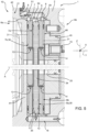
Figure 1 is a partial cross-section of an agricultural vehicle comprising a braking assembly according to the present invention; -
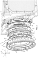
Figure 2 is an exploded view of the braking assembly offigure 1 ; -
Figure 3 is a rear view of the agricultural vehicle ofFigure 1 ; -
Figure 4 is a detailed view ofFigure 1 at an enlarged scale; and -
Figure 5 illustrates the same detailed view illustrated inFigure 4 , in which the path of a fluid is schematically shown. - With reference to
figure 3 ,numeral 1 indicates a work vehicle, in particular an agricultural vehicle such as a tractor.Vehicle 1 comprises amain body 2 and a plurality ofwheels 3, which are rotatable about respective rotational axes A so as to movemain body 2 with respect to the ground.Vehicle 1 further comprises at least onebraking assembly 10, which is adapted to slow down, stop or prevent the rotation of one or morerespective wheels 3 about their respective rotational axes A. - In the embodiment shown,
vehicle 1 comprises two front wheels (not shown) and tworear wheels 4, 5 according to an advancement direction X ofvehicle 1. In detail,figure 3 shows the tworear wheels 4, 5 ofvehicle 1, which are mounted on asame axle 20 ofvehicle 1, are rotatable about coincident rotational axes A and are spaced from each other along a direction Y transversal to advancement direction X. In further detail,vehicle 1 comprises twobraking assemblies 10, which are adapted to brakerear wheel 4 and rear wheel 5, respectively. - For the sake of simplicity, in the following of the present description reference will be made to a
single braking assembly 10 adapted to brakerear wheel 4, the description of abraking assembly 10 adapted to brake rear wheel 5 being identical. - As illustrated in
figure 4 ,braking assembly 10 comprises abrake disc 6, which is rotatable integrally withrear wheel 4 about rotational axis A and defines afirst side 6a and asecond side 6b, which are axially opposite to each other. In other words,first side 6a andsecond side 6b are opposite to each other with respect to a median plane ofbrake disc 6. More specifically,brake disc 6 is mounted onaxle 20 coaxially to rotational axis A andrear wheel 4 is onfirst side 6a with respect tobrake disc 6. -
Braking assembly 10 further comprises twocounter discs brake disc 6 onfirst side 6a andsecond side 6b, respectively, and are rotationally fixed. Preferably,counter discs -
Braking assembly 10 comprises not-shown actuation means, which are adapted to presscounter disc 7 and/orcounter disc 8 againstbrake disc 6, in order to obtain a braking action ofrear wheel 4. - The actuation means may be actuated by a driver of
vehicle 1. In detail, the actuation means are actuated by a brake command oil pressure, which is generated with a master cylinder pump inside the tractor cabin. - Furthermore,
braking assembly 10 comprises afluid inlet 9 for the inlet of a fluid. In detail, this fluid is a coolant fluid or a cooling lubricant fluid. -
Counter disc 7 andbrake disc 6 definefirst interstices 11 with each other;counter disc 8 andbrake disc 6 definesecond interstices 12 with each other. In addition,counter disc 7 is formed with one ormore holes 13, which are adapted to put in fluidiccommunication fluid inlet 9 withfirst interstices 11. Similarly,counter disc 8 is formed with one ormore holes 14, which are adapted to put in fluidiccommunication fluid inlet 9 withsecond interstices 12. - As illustrated in
figure 4 ,counter discs hole 13 ofcounter disc 7 is arranged coaxially to arespective hole 14 ofcounter disc 8. - As illustrated in
figure 2 , eachcounter disc counter discs first faces face brake disc 6 and respectivesecond faces first faces counter discs first interstices 11 are defined by a surface of brake disc onfirst side 6a andfirst face 7a;second interstices 12 are defined by a surface ofbrake disc 6 onsecond side 6b andfirst face 8a. - Each
second face surface 30, which is flat or substantially flat and a plurality ofregions 31 protruding fromsurface 30 parallel to rotational axis A (figure 2 ). -
Regions 31 are shaped like quadrilaterals and extend for at least part of the radial extension ofsurface 30. In detail, eachregion 31 extends radially between a radius that is greater than the inner radius and the outer radius of therespective counter disc region 31 is shaped like an annulus sector. -
Regions 31 of eachcounter disc regions 31 are angularly equidistant from one another and are identical. - More specifically, since
regions 31 of eachcounter disc surface 30,surface 30 defines a plurality ofgrooves 38 with respect toregions 31. - Preferably,
surface 30 andregions 31 are formed in one piece. - As illustrated in
figure 2 ,grooves 38 extend in a radial pattern about rotational axis A. In addition, two angularlyconsecutive grooves 38 of eachcounter disc respective region 31. - In the preferred embodiment shown, each
counter disc regions 31, which are angularly spaced from one another by asmany grooves 38. Moreover, sinceregions 31 are shaped like annulus sectors, the circumferential extension of eachgroove 38 decreases from the inner radius toward the outer radius of therelative counter disc - Furthermore, holes 13 and 14 are through holes and have respective axes that are parallel to one another and to rotational axes A.
-
Holes 13 are radially interposed between the inner radius andregions 31 ofcounter disc 7. Similarly, holes 14 are radially interposed between the inner radius andregions 31 ofcounter disc 8. In addition, preferably,counter discs respective holes respective regions 31. More specifically, eachhole respective region 31. - Furthermore, each
counter disc figures 1 and2 ). In detail, anti-rotational pin holes 32 andanti-rotational pins 33 preventcounter discs brake disc 6 about rotational axis A. - In the embodiment shown, each
counter disc - The radial extension of
counter discs brake disc 6. Preferably, the radial extension ofcounter discs brake disc 6. - As shown in
figure 2 ,brake disc 6 is shaped like a circular disc and comprises acentral portion 34 and a radiallyexternal portion 35 surroundingcentral portion 34. - The external surface of radially
external portion 35 comprises a friction material and is shaped like an annulus.Central portion 34 comprises, in turn, ahole 36, which allowsbrake disc 6 to be mounted toaxle 20 and a plurality of lightening holes 37. In detail,hole 36 is formed at the center ofcentral portion 34 and lighteningholes 37 are angularly equidistant from one another abouthole 36. - Furthermore, the axial extension of radially
external portion 35 is greater than the axial extension ofcentral portion 34. On the contrary, the extension of radiallyexternal portion 35 radially with respect to rotational axis A is preferably lower than the radial extension ofcentral portion 34. - Furthermore, braking
assembly 10 comprises apiston plate 45, which is arranged opposite tobrake disc 6 with respect to counterdisc 8.Piston plate 45 is operatively connected to the not-shown actuation means and is adapted to presscounter disc 7 and/orcounter disc 8 againstbrake disc 6, in order to obtain the braking action ofrear wheel 4.Piston plate 45 is slidable parallel to rotational axis A with respect tomain body 2 as a consequence of the activation of the actuation means. - In addition,
piston plate 45 is shaped like an annulus and comprises asurface 46, which is arranged so as to facesurface 30 ofcounter disc 8. In detail,surface 46 andsurface 30 of counter disc 8 (and, in particular,grooves 38 of counter disc 8) define at least part ofthird interstices 39. - Moreover,
anti-rotational pins 33 ofcounter disc 8 are adapted to engage both anti-rotational pin holes 32 ofcounter disc 8 and respective holes formed in piston plate 45 (figure 1 ) . -
Braking assembly 10 further comprises a limitingdevice 15, which is adapted to limit the movement ofpiston plate 45 within a specific stroke parallel to rotational axis A. In detail, limitingdevice 15 is adapted to limit the movement of piston plate 458 in the direction oriented fromcounter disc 7 to counterdisc 8. This allows to control the stroke ofpiston plate 45 parallel to axis A in case of wear of brake disc 6.Braking assembly 10 further comprises acover 21, which is arranged coaxially to rotational axis A and opposite tobrake disc 6 with respect to counterdisc 7. -
Cover 21 comprises acentral portion 41 and a radiallyexternal portion 42 surroundingcentral portion 41 and having an axial extension parallel to rotationalaxis A. Cover 21 is shaped like an annulus having a radial extension greater than the radial extension ofbrake disc 6 andcounter discs axle 20. - In particular,
central portion 41 andexternal portion 42 form a single piece. - Furthermore, cover 21 is adapted to be fixed to
frame 2 at radiallyexternal portion 42 by connectingmeans 40, such as threaded connecting means (figure 2 ). As illustrated infigure 1 , whencover 21 is fixed toframe 2, cover 21 andframe 2 define acavity 50, which is adapted to house at leastbrake disc 6,counter discs piston plate 45. -
Counter disc 7 is fixed to cover 21. More specifically, cover 21 is at least partially in contact withcounter disc 7 and, in particular, withregions 31. In addition,cover 21 andsurface 30 of counter disc 7 (and, in particular, grooves 38) define at least part offourth interstices 43. - Moreover,
anti-rotational pins 33 ofcounter disc 7 are adapted to engage both anti-rotational pin holes 32 ofcounter disc 7 and respective holes formed in cover 21 (figure 1 ). - In particular,
fluid inlet 9 comprises an opening formed atcover 21 and is fluidly connected tocavity 50. More specifically,fluid inlet 9 is arranged at radiallyexternal portion 42 and is fluidly connected tocavity 50 by means of one ormore ducts 51. - As illustrated in
figure 1 ,ducts 51 are formed partly insidecover 21 and partly insidemain body 2. In addition,fluid inlet 9 is arranged abovebrake disc 6 andcounter discs - In addition,
ducts 51 are in fluidic communication with third andfourth interstices Third interstices 39, in turn, are in fluidic communication withsecond interstices 12 throughholes 14 andfourth interstices 43 are in fluidic communication withfirst interstices 11 through holes 13 (figure 2 ). - Furthermore, braking
assembly 10 comprises afluid outlet 16 for the outlet of the fluid (figure 4 ). Preferably,fluid outlet 16 is arranged belowbrake disc 6 andcounter discs - The fluid is forced to circulate between
fluid inlet 9 andfluid outlet 16 by means of a pump ofvehicle 1, which is known per se and is not described further in detail. The pump may be, by way of example, a reciprocating pump or a turbopump. -
Brake disc 6 andcounter discs brake disc 6 andcounter discs second interstices cavity 50 according to vertical direction Z. In other words, because of gravity, the fluid passing through first andsecond interstices cavity 50, which acts as a sump. The collected fluid has a fluid level and is adapted to be splashed overbrake disc 6 because of the rotation thereof about rotational axis A. Therefore,brake disc 6 is cooled also by means of passive cooling. - The operation of the
braking assembly 10 according to the present invention and described as above is the following. In particular, reference will be made to thebraking assembly 10 adapted to brakerear wheel 4, the operation ofbraking assembly 10 adapted to brake rear wheel 5 being identical. - In use, the actuation means are activated so as to press
counter disc 7 and/orcounter disc 8 againstbrake disc 6, and to obtain the braking action ofrear wheel 4. During the braking action, the fluid is forced to circulate betweenfluid inlet 9 andfluid outlet 16 in order to carry out the forced cooling ofbrake disc 6. Alternatively, the fluid may be continuously forced to circulate betweenfluid inlet 9 andfluid outlet 16 independently of the braking action and, in particular, even after the braking action has stopped. - In detail, the fluid is input into
cavity 50 throughfluid inlet 9, which is arranged abovebrake disc 6 andcounter discs 7, 8 (figure 5 ). - In further detail, the input fluid flows through
ducts 51 to third andfourth interstices grooves 38 ofcounter disc 7 from the outer radius toward the inner radius thereof and reaches holes 13. Simultaneously, the fluid flows acrossgrooves 38 ofcounter disc 8 from the outer radius toward the inner radius thereof and reaches holes 14. - Subsequently, as illustrated in
figure 5 , the fluid flows throughholes second interstices brake disc 6 and, in particular, with radiallyexternal portion 35. As a consequence, the waste heat generated during the braking action of brakingassembly 10 is transmitted to the fluid and the fluid cools theentire brake disc 6. - In conclusion, the fluid entering from
fluid inlet 9 and passing through first andsecond interstices brake disc 6. - Subsequently, as a result of the rotation of
brake disc 6 about rotational axis A and the corresponding centrifugal forces, the fluid is transported radially outwards and tends to accumulate in the lowermost part ofcavity 50, because of gravity. The fluid is then output through fluid outlet 16 (figure 5 ). As a consequence, the flow of waste heat dissipated from brakingassembly 10 is opposite to the flow of the fluid during the forced cooling. In other words, the flow of the fluid is in counterflow with respect to the flow of waste heat. - Furthermore, since
brake disc 6 is partially immersed in the fluid collected in the lowermost part of cavity, such fluid is splashed overbrake disc 6 as a result of the rotation thereof about rotational axis A. - In view of the foregoing, the advantages of
braking assembly 10 andwork vehicle 1 according to the invention are apparent. - In particular, since braking
assembly 10 comprisescounter discs second interstices external portion 35 on both first andsecond sides brake disc 6 is obtained. In other words,brake disc 6 is cooled at two opposite thermal exchange surfaces. Accordingly, it has been observed that the service life of brakingassembly 10 is considerably extended and the brake performances are significantly improved. - In addition, since the fluid is adapted to flow across third and fourth interstices and through
holes counter discs counter discs external faces brake disc 6 is in proximity to efficiently cooled down components. -
Brake disc 6 is partially immersed in the fluid collected in the lowermost portion ofcavity 50. Accordingly, the fluid splashed over the surfaces ofbrake disc 6 because of the rotation ofbrake disc 6 contributes to disperse the waste heat by virtue of passive cooling. However, since the waste heat is mainly dispersed by forced cooling, the level of the fluid in whichbrake disc 6 is immersed may be set lower than the fluid level of the known disc brakes discussed in the introductory portion of the present description. As a result, the power losses due to the rotation ofbrake disc 6 immersed in the fluid are very low. - Moreover, since the fluid adapted to contact
brake disc 6 may be a cooling lubricant fluid, brakingassembly 10 can be effectively lubricated while being cooled. -
Counter disc assembly 10 can be advantageously kept low. - It is clear that modifications can be made to the described
braking assembly 10 andwork vehicle 1 which do not extend beyond the scope of protection defined by the claims. In particular, brakingassembly 10 might comprise more than onefluid inlet 9 and/or more than onefluid outlet 16. - Furthermore,
counter disks central portion 41 andpiston plate 45. Accordingly, the number of components ofbraking assembly 10 can be advantageously reduced.
Claims (10)
- Braking assembly (10) for a work vehicle (1) comprising:- a brake disc (6), which is rotatable integrally with at least one wheel (3, 4, 5) of said work vehicle (1) about a rotational axis (A);- a first counter disc (7), which is arranged on a first side (6a) of said brake disc (6) along said rotational axis (A) and is rotationally fixed;- a second counter disc (8), which is arranged on a second side (6b) of said brake disc (6) opposite to said first side (6a) along said rotational axis (A) and is rotationally fixed;- at least one fluid inlet (9) for the inlet of a fluid; said fluid being a cooling lubricant fluid; and- actuation means, which are adapted to press said first and/or second counter discs (7, 8) against said brake disc (6) ;said first and second counter discs (7, 8) defining respectively first and second interstices (11, 12) with said brake disc (6); said first and second counter discs (7, 8) being respectively formed with at least one first hole (13) and at least one second hole (14), which are respectively adapted put in fluidic communication said at least one fluid inlet (9) with said first interstices (11) and said second interstices (12).
- Braking assembly according to claim 1 further comprising:- a cover (21), which is opposite to said brake disc (6) with respect to said first counter disc (7) and is rotationally fixed; and- a piston plate (45), which is opposite to said brake disc (6) with respect to said second counter disc (8) and is operatively connected to said actuation means;said piston plate (45) defining third interstices (39) with said second counter disc (8); said third interstices (39) being fluidly connected to said fluid inlet (9) and to said second interstices (12) through said at least one second hole (14) ;said cover (21) defining fourth interstices (43) with said first counter disc (7); said fourth interstices (43) being fluidly connected to said fluid inlet (9) and to said first interstices (11) through said at least one first hole (13) .
- Braking assembly according to claim 2, wherein said fluid inlet (9) comprises an opening arranged at said cover (21) and is fluidly connected to said third and fourth interstices (39, 43) by means of one or more ducts (51).
- Braking assembly according to any one of claims 2 or 3, wherein said first and second counter discs (7, 8) comprise:- respective first faces (7a, 8a), which are adapted to face said brake disc (6) respectively on said first side (6a) and said second side (6b); and- respective second faces (7b, 8b), which are each opposite to a respective said first face (7a, 8a);each said second face (7b, 8b) comprising a surface (30), which is flat, and a plurality of regions (31) protruding from said surface (30) parallel to said rotational axis (A);said regions (31) of each said second face (7b, 8b) being angularly spaced from one another with respect to said rotational axis (A) and defining a plurality of grooves (38);said grooves (38) of said first counter disc (7) and said cover (21) defining at least part of said fourth interstices (43); said grooves (38) of said second counter disc (8) and said piston plate (45) defining at least part of said third interstices (39).
- Braking assembly according to claim 4, wherein said grooves (38) of both first and second counter discs (7, 8) are arranged in a radial pattern with respect to said rotational axis (A).
- Braking assembly according to any one of the foregoing claims, further comprising at least one fluid outlet (16) for the outlet of said fluid;
said fluid inlet (9) and said fluid outlet (16) being arranged respectively above and below said brake disc (6) with respect to a vertical direction (Z), which is parallel to the gravitational acceleration vector. - Braking assembly according to any one of the foregoing claims, wherein said first counter disc (7) and said second counter disc (8) are identical.
- Braking assembly according to any one of the foregoing claims, wherein said brake disc (6) is partially immersed in said fluid.
- A work vehicle (1) comprising:- a main body (2);- a plurality of wheels (3, 4, 5), which are adapted to move said main body (2) with respect to the ground; and- at least one braking assembly (10) according to any one of the foregoing claims, which is adapted to brake, in use, one or more of said plurality of wheels (3, 4, 5).
- The work vehicle according to claim 9, further comprising a pump, which is adapted to circulate a fluid between a fluid inlet (9) and a fluid outlet (16) of said at least one braking assembly (10).
Applications Claiming Priority (1)
| Application Number | Priority Date | Filing Date | Title |
|---|---|---|---|
| IT102021000025850A IT202100025850A1 (en) | 2021-10-08 | 2021-10-08 | BRAKING ASSEMBLY FOR A WORK VEHICLE AND WORK VEHICLE INCLUDING SUCH BRAKING ASSEMBLY |
Publications (2)
| Publication Number | Publication Date |
|---|---|
| EP4163513A1 true EP4163513A1 (en) | 2023-04-12 |
| EP4163513B1 EP4163513B1 (en) | 2025-08-27 |
Family
ID=79018754
Family Applications (1)
| Application Number | Title | Priority Date | Filing Date |
|---|---|---|---|
| EP22199906.3A Active EP4163513B1 (en) | 2021-10-08 | 2022-10-05 | Braking assembly for a work vehicle and work vehicle comprising such braking assembly |
Country Status (2)
| Country | Link |
|---|---|
| EP (1) | EP4163513B1 (en) |
| IT (1) | IT202100025850A1 (en) |
Citations (9)
| Publication number | Priority date | Publication date | Assignee | Title |
|---|---|---|---|---|
| GB998578A (en) * | 1962-05-01 | 1965-07-14 | Lambert & Brake Corp | Friction device |
| DE2331315A1 (en) * | 1973-06-20 | 1975-01-23 | Voith Getriebe Kg | Multi-plate clutch for gear box drive - provides cooling radial and spiral pressure supplied oil grooves in clutch plates |
| US4646880A (en) * | 1985-11-29 | 1987-03-03 | Dana Corporation | Planetary wheel end with wet brake |
| US4815573A (en) * | 1986-10-02 | 1989-03-28 | Akebono Brake Industry Co., Ltd | Liquid-cooled disc brake |
| EP0987459A2 (en) | 1998-09-15 | 2000-03-22 | Borg-Warner Automotive, Inc. | Multi-disk friction device having forced lubrication on demand |
| EP1081401A2 (en) | 1999-08-24 | 2001-03-07 | BorgWarner Inc. | Multi-disk device having forced lubrication on demand |
| DE10300614A1 (en) | 2003-01-10 | 2004-07-22 | Zf Friedrichshafen Ag | Multi-disk wet brake, comprising bore at activator for lubricant to be guided into inner space |
| US20120061191A1 (en) * | 2009-04-02 | 2012-03-15 | Knorr-Bremse Systeme Fuer Nutzfahrzeuge Gmbh | Wet-Running Multiple Disc Brake and System |
| US10151366B2 (en) * | 2014-12-27 | 2018-12-11 | Kinetics Drive Solutions Inc. | Cooling system for multi-disc brake assembly |
-
2021
- 2021-10-08 IT IT102021000025850A patent/IT202100025850A1/en unknown
-
2022
- 2022-10-05 EP EP22199906.3A patent/EP4163513B1/en active Active
Patent Citations (9)
| Publication number | Priority date | Publication date | Assignee | Title |
|---|---|---|---|---|
| GB998578A (en) * | 1962-05-01 | 1965-07-14 | Lambert & Brake Corp | Friction device |
| DE2331315A1 (en) * | 1973-06-20 | 1975-01-23 | Voith Getriebe Kg | Multi-plate clutch for gear box drive - provides cooling radial and spiral pressure supplied oil grooves in clutch plates |
| US4646880A (en) * | 1985-11-29 | 1987-03-03 | Dana Corporation | Planetary wheel end with wet brake |
| US4815573A (en) * | 1986-10-02 | 1989-03-28 | Akebono Brake Industry Co., Ltd | Liquid-cooled disc brake |
| EP0987459A2 (en) | 1998-09-15 | 2000-03-22 | Borg-Warner Automotive, Inc. | Multi-disk friction device having forced lubrication on demand |
| EP1081401A2 (en) | 1999-08-24 | 2001-03-07 | BorgWarner Inc. | Multi-disk device having forced lubrication on demand |
| DE10300614A1 (en) | 2003-01-10 | 2004-07-22 | Zf Friedrichshafen Ag | Multi-disk wet brake, comprising bore at activator for lubricant to be guided into inner space |
| US20120061191A1 (en) * | 2009-04-02 | 2012-03-15 | Knorr-Bremse Systeme Fuer Nutzfahrzeuge Gmbh | Wet-Running Multiple Disc Brake and System |
| US10151366B2 (en) * | 2014-12-27 | 2018-12-11 | Kinetics Drive Solutions Inc. | Cooling system for multi-disc brake assembly |
Also Published As
| Publication number | Publication date |
|---|---|
| IT202100025850A1 (en) | 2023-04-08 |
| EP4163513B1 (en) | 2025-08-27 |
Similar Documents
| Publication | Publication Date | Title |
|---|---|---|
| EP1996828B1 (en) | Liquid-cooled disc brakes | |
| US2928504A (en) | Heavy duty oil-cooled friction device | |
| SE523539C2 (en) | axle assembly | |
| KR102217929B1 (en) | Friction brake and vehicle-mounted apparatus | |
| US5293967A (en) | Shielded vehicle brake | |
| US4011930A (en) | Means to present lubricating and cooling fluid to friction material in a wet brake system | |
| US4049084A (en) | Audible lining wear indicator | |
| US5474160A (en) | Ring brake and caliper cooled by air flow | |
| JP2020534495A (en) | Brake device | |
| EP4163513B1 (en) | Braking assembly for a work vehicle and work vehicle comprising such braking assembly | |
| CA2289799A1 (en) | Improved rotor for disk brake assembly | |
| CA2969351C (en) | Improved cooling system for multi-disc brake assembly | |
| ZA200503844B (en) | Wheel hub. | |
| EP1499814B2 (en) | Disc brake pad | |
| EP2310712B1 (en) | Brake assembly or clutch unit for a motor vehicle | |
| KR100520282B1 (en) | Drum Brake | |
| US20050252730A1 (en) | Wheel hub | |
| KR20110059036A (en) | Integrated hub structure to block braking heat | |
| GB2343721A (en) | Friction disc for a clutch or disc brake | |
| ZA200509377B (en) | Fluid cooled wet brake system | |
| CN113565906B (en) | Dynamic friction plates, wet hydraulic brakes and aerial work platforms | |
| KR200337397Y1 (en) | Break disk for automobils | |
| IT202300007668A1 (en) | BRAKING ASSEMBLY FOR A WORKING VEHICLE AND METHOD OF CHECKING THE LUBRICATION OF A BRAKING ASSEMBLY | |
| JP2000052944A (en) | Vehicle drum brake structure and vehicle | |
| AU2004245580A1 (en) | Fluid cooled wet brake system |
Legal Events
| Date | Code | Title | Description |
|---|---|---|---|
| PUAI | Public reference made under article 153(3) epc to a published international application that has entered the european phase |
Free format text: ORIGINAL CODE: 0009012 |
|
| STAA | Information on the status of an ep patent application or granted ep patent |
Free format text: STATUS: THE APPLICATION HAS BEEN PUBLISHED |
|
| AK | Designated contracting states |
Kind code of ref document: A1 Designated state(s): AL AT BE BG CH CY CZ DE DK EE ES FI FR GB GR HR HU IE IS IT LI LT LU LV MC ME MK MT NL NO PL PT RO RS SE SI SK SM TR |
|
| STAA | Information on the status of an ep patent application or granted ep patent |
Free format text: STATUS: REQUEST FOR EXAMINATION WAS MADE |
|
| 17P | Request for examination filed |
Effective date: 20231012 |
|
| RBV | Designated contracting states (corrected) |
Designated state(s): AL AT BE BG CH CY CZ DE DK EE ES FI FR GB GR HR HU IE IS IT LI LT LU LV MC ME MK MT NL NO PL PT RO RS SE SI SK SM TR |
|
| GRAP | Despatch of communication of intention to grant a patent |
Free format text: ORIGINAL CODE: EPIDOSNIGR1 |
|
| STAA | Information on the status of an ep patent application or granted ep patent |
Free format text: STATUS: GRANT OF PATENT IS INTENDED |
|
| INTG | Intention to grant announced |
Effective date: 20250321 |
|
| GRAS | Grant fee paid |
Free format text: ORIGINAL CODE: EPIDOSNIGR3 |
|
| GRAA | (expected) grant |
Free format text: ORIGINAL CODE: 0009210 |
|
| STAA | Information on the status of an ep patent application or granted ep patent |
Free format text: STATUS: THE PATENT HAS BEEN GRANTED |
|
| AK | Designated contracting states |
Kind code of ref document: B1 Designated state(s): AL AT BE BG CH CY CZ DE DK EE ES FI FR GB GR HR HU IE IS IT LI LT LU LV MC ME MK MT NL NO PL PT RO RS SE SI SK SM TR |
|
| REG | Reference to a national code |
Ref country code: CH Ref legal event code: EP |
|
| REG | Reference to a national code |
Ref country code: DE Ref legal event code: R096 Ref document number: 602022020134 Country of ref document: DE |
|
| REG | Reference to a national code |
Ref country code: IE Ref legal event code: FG4D |
|
| REG | Reference to a national code |
Ref country code: NL Ref legal event code: MP Effective date: 20250827 |
|
| PG25 | Lapsed in a contracting state [announced via postgrant information from national office to epo] |
Ref country code: IS Free format text: LAPSE BECAUSE OF FAILURE TO SUBMIT A TRANSLATION OF THE DESCRIPTION OR TO PAY THE FEE WITHIN THE PRESCRIBED TIME-LIMIT Effective date: 20251227 |
|
| PGFP | Annual fee paid to national office [announced via postgrant information from national office to epo] |
Ref country code: DE Payment date: 20251028 Year of fee payment: 4 |
|
| PG25 | Lapsed in a contracting state [announced via postgrant information from national office to epo] |
Ref country code: NO Free format text: LAPSE BECAUSE OF FAILURE TO SUBMIT A TRANSLATION OF THE DESCRIPTION OR TO PAY THE FEE WITHIN THE PRESCRIBED TIME-LIMIT Effective date: 20251127 |
|
| REG | Reference to a national code |
Ref country code: LT Ref legal event code: MG9D |
|
| PG25 | Lapsed in a contracting state [announced via postgrant information from national office to epo] |
Ref country code: PT Free format text: LAPSE BECAUSE OF FAILURE TO SUBMIT A TRANSLATION OF THE DESCRIPTION OR TO PAY THE FEE WITHIN THE PRESCRIBED TIME-LIMIT Effective date: 20251229 |
|
| PG25 | Lapsed in a contracting state [announced via postgrant information from national office to epo] |
Ref country code: FI Free format text: LAPSE BECAUSE OF FAILURE TO SUBMIT A TRANSLATION OF THE DESCRIPTION OR TO PAY THE FEE WITHIN THE PRESCRIBED TIME-LIMIT Effective date: 20250827 |
|
| PGFP | Annual fee paid to national office [announced via postgrant information from national office to epo] |
Ref country code: IT Payment date: 20251031 Year of fee payment: 4 |
|
| PG25 | Lapsed in a contracting state [announced via postgrant information from national office to epo] |
Ref country code: HR Free format text: LAPSE BECAUSE OF FAILURE TO SUBMIT A TRANSLATION OF THE DESCRIPTION OR TO PAY THE FEE WITHIN THE PRESCRIBED TIME-LIMIT Effective date: 20250827 Ref country code: NL Free format text: LAPSE BECAUSE OF FAILURE TO SUBMIT A TRANSLATION OF THE DESCRIPTION OR TO PAY THE FEE WITHIN THE PRESCRIBED TIME-LIMIT Effective date: 20250827 |
|
| PGFP | Annual fee paid to national office [announced via postgrant information from national office to epo] |
Ref country code: FR Payment date: 20251027 Year of fee payment: 4 |
|
| PG25 | Lapsed in a contracting state [announced via postgrant information from national office to epo] |
Ref country code: GR Free format text: LAPSE BECAUSE OF FAILURE TO SUBMIT A TRANSLATION OF THE DESCRIPTION OR TO PAY THE FEE WITHIN THE PRESCRIBED TIME-LIMIT Effective date: 20251128 |
|
| PG25 | Lapsed in a contracting state [announced via postgrant information from national office to epo] |
Ref country code: SE Free format text: LAPSE BECAUSE OF FAILURE TO SUBMIT A TRANSLATION OF THE DESCRIPTION OR TO PAY THE FEE WITHIN THE PRESCRIBED TIME-LIMIT Effective date: 20250827 |
|
| PG25 | Lapsed in a contracting state [announced via postgrant information from national office to epo] |
Ref country code: LV Free format text: LAPSE BECAUSE OF FAILURE TO SUBMIT A TRANSLATION OF THE DESCRIPTION OR TO PAY THE FEE WITHIN THE PRESCRIBED TIME-LIMIT Effective date: 20250827 |
|
| PG25 | Lapsed in a contracting state [announced via postgrant information from national office to epo] |
Ref country code: BG Free format text: LAPSE BECAUSE OF FAILURE TO SUBMIT A TRANSLATION OF THE DESCRIPTION OR TO PAY THE FEE WITHIN THE PRESCRIBED TIME-LIMIT Effective date: 20250827 Ref country code: PL Free format text: LAPSE BECAUSE OF FAILURE TO SUBMIT A TRANSLATION OF THE DESCRIPTION OR TO PAY THE FEE WITHIN THE PRESCRIBED TIME-LIMIT Effective date: 20250827 |
|
| PG25 | Lapsed in a contracting state [announced via postgrant information from national office to epo] |
Ref country code: RS Free format text: LAPSE BECAUSE OF FAILURE TO SUBMIT A TRANSLATION OF THE DESCRIPTION OR TO PAY THE FEE WITHIN THE PRESCRIBED TIME-LIMIT Effective date: 20251127 |
|
| PG25 | Lapsed in a contracting state [announced via postgrant information from national office to epo] |
Ref country code: ES Free format text: LAPSE BECAUSE OF FAILURE TO SUBMIT A TRANSLATION OF THE DESCRIPTION OR TO PAY THE FEE WITHIN THE PRESCRIBED TIME-LIMIT Effective date: 20250827 |
|
| REG | Reference to a national code |
Ref country code: AT Ref legal event code: MK05 Ref document number: 1830227 Country of ref document: AT Kind code of ref document: T Effective date: 20250827 |
|
| PG25 | Lapsed in a contracting state [announced via postgrant information from national office to epo] |
Ref country code: RO Free format text: LAPSE BECAUSE OF FAILURE TO SUBMIT A TRANSLATION OF THE DESCRIPTION OR TO PAY THE FEE WITHIN THE PRESCRIBED TIME-LIMIT Effective date: 20250827 |
|
| PG25 | Lapsed in a contracting state [announced via postgrant information from national office to epo] |
Ref country code: SM Free format text: LAPSE BECAUSE OF FAILURE TO SUBMIT A TRANSLATION OF THE DESCRIPTION OR TO PAY THE FEE WITHIN THE PRESCRIBED TIME-LIMIT Effective date: 20250827 |
|
| PG25 | Lapsed in a contracting state [announced via postgrant information from national office to epo] |
Ref country code: DK Free format text: LAPSE BECAUSE OF FAILURE TO SUBMIT A TRANSLATION OF THE DESCRIPTION OR TO PAY THE FEE WITHIN THE PRESCRIBED TIME-LIMIT Effective date: 20250827 |
|
| PG25 | Lapsed in a contracting state [announced via postgrant information from national office to epo] |
Ref country code: AT Free format text: LAPSE BECAUSE OF FAILURE TO SUBMIT A TRANSLATION OF THE DESCRIPTION OR TO PAY THE FEE WITHIN THE PRESCRIBED TIME-LIMIT Effective date: 20250827 |
|
| PG25 | Lapsed in a contracting state [announced via postgrant information from national office to epo] |
Ref country code: CZ Free format text: LAPSE BECAUSE OF FAILURE TO SUBMIT A TRANSLATION OF THE DESCRIPTION OR TO PAY THE FEE WITHIN THE PRESCRIBED TIME-LIMIT Effective date: 20250827 |
|
| PG25 | Lapsed in a contracting state [announced via postgrant information from national office to epo] |
Ref country code: SK Free format text: LAPSE BECAUSE OF FAILURE TO SUBMIT A TRANSLATION OF THE DESCRIPTION OR TO PAY THE FEE WITHIN THE PRESCRIBED TIME-LIMIT Effective date: 20250827 Ref country code: EE Free format text: LAPSE BECAUSE OF FAILURE TO SUBMIT A TRANSLATION OF THE DESCRIPTION OR TO PAY THE FEE WITHIN THE PRESCRIBED TIME-LIMIT Effective date: 20250827 |
|
| REG | Reference to a national code |
Ref country code: CH Ref legal event code: H13 Free format text: ST27 STATUS EVENT CODE: U-0-0-H10-H13 (AS PROVIDED BY THE NATIONAL OFFICE) Effective date: 20260527 |
|
| REG | Reference to a national code |
Ref country code: DE Ref legal event code: R097 Ref document number: 602022020134 Country of ref document: DE |
|
| PG25 | Lapsed in a contracting state [announced via postgrant information from national office to epo] |
Ref country code: LU Free format text: LAPSE BECAUSE OF NON-PAYMENT OF DUE FEES Effective date: 20251005 |
|
| REG | Reference to a national code |
Ref country code: BE Ref legal event code: MM Effective date: 20251031 |
|
| PG25 | Lapsed in a contracting state [announced via postgrant information from national office to epo] |
Ref country code: LT Free format text: LAPSE BECAUSE OF FAILURE TO SUBMIT A TRANSLATION OF THE DESCRIPTION OR TO PAY THE FEE WITHIN THE PRESCRIBED TIME-LIMIT Effective date: 20250827 Ref country code: MC Free format text: LAPSE BECAUSE OF FAILURE TO SUBMIT A TRANSLATION OF THE DESCRIPTION OR TO PAY THE FEE WITHIN THE PRESCRIBED TIME-LIMIT Effective date: 20250827 |
|
| PLBE | No opposition filed within time limit |
Free format text: ORIGINAL CODE: 0009261 |
|
| STAA | Information on the status of an ep patent application or granted ep patent |
Free format text: STATUS: NO OPPOSITION FILED WITHIN TIME LIMIT |
|
| REG | Reference to a national code |
Ref country code: CH Ref legal event code: L10 Free format text: ST27 STATUS EVENT CODE: U-0-0-L10-L00 (AS PROVIDED BY THE NATIONAL OFFICE) Effective date: 20260708 |
|
| PG25 | Lapsed in a contracting state [announced via postgrant information from national office to epo] |
Ref country code: BE Free format text: LAPSE BECAUSE OF NON-PAYMENT OF DUE FEES Effective date: 20251031 Ref country code: CH Free format text: LAPSE BECAUSE OF NON-PAYMENT OF DUE FEES Effective date: 20251031 |
|
| 26N | No opposition filed |
Effective date: 20260528 |