EP4163450A1 - Anti-splash device for pergolas - Google Patents
Anti-splash device for pergolas Download PDFInfo
- Publication number
- EP4163450A1 EP4163450A1 EP22200661.1A EP22200661A EP4163450A1 EP 4163450 A1 EP4163450 A1 EP 4163450A1 EP 22200661 A EP22200661 A EP 22200661A EP 4163450 A1 EP4163450 A1 EP 4163450A1
- Authority
- EP
- European Patent Office
- Prior art keywords
- tab
- water
- pergolas
- slat
- slats
- Prior art date
- Legal status (The legal status is an assumption and is not a legal conclusion. Google has not performed a legal analysis and makes no representation as to the accuracy of the status listed.)
- Granted
Links
Images


Classifications
-
- E—FIXED CONSTRUCTIONS
- E04—BUILDING
- E04F—FINISHING WORK ON BUILDINGS, e.g. STAIRS, FLOORS
- E04F10/00—Sunshades, e.g. Florentine blinds or jalousies; Outside screens; Awnings or baldachins
- E04F10/08—Sunshades, e.g. Florentine blinds or jalousies; Outside screens; Awnings or baldachins of a plurality of similar rigid parts, e.g. slabs, lamellae
- E04F10/10—Sunshades, e.g. Florentine blinds or jalousies; Outside screens; Awnings or baldachins of a plurality of similar rigid parts, e.g. slabs, lamellae collapsible or extensible; metallic Florentine blinds; awnings with movable parts such as louvres
-
- E—FIXED CONSTRUCTIONS
- E04—BUILDING
- E04B—GENERAL BUILDING CONSTRUCTIONS; WALLS, e.g. PARTITIONS; ROOFS; FLOORS; CEILINGS; INSULATION OR OTHER PROTECTION OF BUILDINGS
- E04B7/00—Roofs; Roof construction with regard to insulation
- E04B7/16—Roof structures with movable roof parts
- E04B7/163—Roof structures with movable roof parts characterised by a pivoting movement of the movable roof parts
Definitions
- the device comprises a tab for drainage of slats, preferably movable, of structures with top enclosure and sun protection that facilitates the evacuation of water and prevents unwanted splashing inside the structure
- Said tab is located at the ends of the water channel of the slats and is arranged in such a way that it bridges the distance between the end of the water channel and the surface, normally upright and perpendicular to this channel, such as the side of a beam or other type of profile, and which is part of the clamping frame of the slats.
- the rainwater that falls on the pergola is channelled through the water channel of the slats to at least one of its ends, to then pass through said tab and the surface perpendicular to said channel, to a gutter which collects it and carries it towards a downspout.
- the problem lies in the fact that, in the passage of the water channel of the slats to the gutter or drainage element, there may be drips and splashes towards the interior of the pergola.
- the invention claimed comprises a tab that channels the water from the end of the water channel of the slat to the side of the surface perpendicular to the channel and at that point, due to the geometry of the tab, it presses on the water drop breaking its surface tension so that the water, by capillary effect, runs down said surface to the gutter avoiding splashes.
- the field of action of this device is, preferably, that of structures with top enclosure or pergolas, although it can be applied to any drainage channel that one wants to evacuate without splashing on a lower channel.
- Patent WO02092938 consists of a roofing device comprising a plurality of roll-up or roll-out roof elements arranged successively with an inclination which by gravity directs water to the side channels on the sides.
- European patent EP2589720 consists of an adjustable blade-shaped device that forms a protective roof, which at one of its ends has a part that helps the evacuation of water that due to its structure prevents the directing and increase of water on the lower surface of the blade.
- patent WO2014136095 presents a structure with slat top enclosure, comprising several slats rotatably arranged, a slat gutter on a first longitudinal side and inclined towards an exit opening, and a side gutter extending essentially perpendicular to the slats under the respective exit openings, and that, facing away from the slats, an upright outer side wall is positioned, extending at least partly next to the slats, wherein said slat roof has increased tightness at the location of the slat drain to the side gutter due to one or more seals extending at least below the outlet opening of each slat extending from each slat to a location adjacent to said upright outer side wall.
- This structure does not have a top flap on the sides of the slats that prevents the water from pouring over the sides where there is no anti-splash seal, in addition, in the event that the seals become obstructed by dirt, the device becomes more likely to cause unnecessary drips outside the area of the channels that direct the rain water.
- utility model ES1208711 which consists of a structure with top enclosure and water collecting profile consisting of a water collecting profile on the sides of the beam which has a mesh that breaks the drop minimising the splash thereof, can also be affected by the plugging of said mesh by dirt, generating an increase in splashes towards the inside of the structure.
- the invention consists of an anti-splash device arranged in a top enclosure, being preferably designed for a slat pergola and preferably for movable slats.
- this element will comprise a vertical surface arranged perpendicular to the slats, although there may be embodiments wherein this surface is not perfectly vertical nor perfectly perpendicular.
- the beams accommodate the bushings for housing the slat shafts.
- the ends of the slats have closing parts called headers, it being typical for the slat shaft to be supported by the headers.
- the device that is claimed comprises a tab between the header and the beam, bridging the distance between both.
- Each of the slats has a longitudinal channel that collects the rainwater and directs it towards at least one of the ends of the slat that is open.
- longitudinal channel water channel and its open end or ends outlet or outlets.
- the tab is arranged at the outlet of the water channel, bridging the distance between the header and the beam in such a way that it collects the water from the water channel and directs it against the beam.
- the water from the channel runs down the tab and, when impacting against the beam, runs down the side thereof by capillary effect to a lower gutter that runs longitudinally along said beam, totally or partially, and carries the water towards a drain to the ground preferably arranged in one of the pillars. This facilitates the drainage avoiding generating splashes inside the pergola.
- the tab has a slope from the water channel to the beam. It also has raised flanges by way of a parapet that facilitate the channelling of water towards the beam, preventing it from overflowing on the sides and falling directly into the gutter, generating splashes.
- the tab is located between the end of the slat and the beam, bridging the gap between the two.
- the header has an upper extension by way of a fin that carries the water that can run along the surface of the slat towards the water channel, preventing it from falling freely from the end of the slat towards the gutter and splashing.
- the fin is located over the entire side of each of the slats collecting and guiding the water that can move along the sides towards the gutter, in the case, for example, that there is no upper extension of the header.
- the tab may be in the form of a ramp, with or without grooves, or any other shape that generates a slope such that it allows the running and channelling of water from the water channel to the beam.
- the tab is shaped as a downward convex curve.
- the tab is secured by one of its ends to the header at the point wherein the water channel pours, such that it enables the passage of water from the channel to the tab.
- the other end of the tab is in contact with the inner side of the beam.
- the drain gutter is located at a lower level of the same inner side of the beam.
- the device may be installed at the time of mounting the pergola or may be subsequently installed at the customer's discretion.
- the tab has longitudinal grooves that guide the water over this surface, meaning that when the water reaches the other end of the tab, which is in contact with the side of the beam, it will break the surface tension and by capillarity the water will run down said side of the beam until it reaches the gutter.
- the tab is preferably made of flexible material.
- the invention relates to an anti-splash device arranged in a pergola of movable slats, where it is common to find a frame comprising pillars and beams where the latter have supports for the bushings housing the shafts of the movable slats.
- the movable slats (4) have at their ends headers that close the piece laterally, the slat shaft being supported by the headers.
- the device comprises a tab (1) between the header (2) and the inner face (3) of the beam (10), bridging the distance between them.
- the tab (1) is made of flexible material, and presses against the inner side (3) of the beam (10).
- Each movable slat has a water channel (5) which is the longitudinal channel that collects all the rain water falling on the movable slats and directs it towards at least one of the ends of said slats.
- the tab (1) is located at the outlet of the water channel and bridges the distance between the slat, in particular from the header (2) and the inner face (3) of the beam and directs the water from the water channel against that inner face of the beam.
- the water that falls on the moving slats (4) runs through the water channel (5) towards the tab (1) where it runs towards the inner face (3) of the beam, falling against it and breaking the surface tension of the water that, due to capillarity, runs down the inner face (3) of the beam towards a gutter (6) located at a level lower than the tab (1).
- This gutter (6) runs longitudinally along the inner face (3) of the beam (10), at least from the point where the tab is located, to a drain such that water falling into the gutter is carried to a drain, preferably arranged in the pillars thus preventing generating splashes inside the enclosure.
- the tab (1) has a convex curved shape on a slope that goes from its highest point at the outlet of the water channel (5) of each of the slats to its lowest point which is the point of contact with the inner face (3) of the beam.
- the grooves (7) on its top face facing downstream allow the water to be directed uniformly.
- the tab (1) further comprises flanges (8) that prevent water from overflowing and falling directly into the gutter (6) causing splashes inside the enclosure.
- the slats have, at their ends, at their top part, fins (9) that act as barriers. These fins are preferably an extension of the headers, which act by preventing water from the top part of the slat from falling freely over its ends. To do this, these fins carry the water towards the water channel (5).
- the tab is fixed to the slat through removable means, such as screws, which allows on the one hand its mounting at the time of construction of the assembly or its inclusion at a later time, in the same way as it that allows the maintenance and easy replacement of a tab that may have been damaged.
Landscapes
- Engineering & Computer Science (AREA)
- Architecture (AREA)
- Civil Engineering (AREA)
- Structural Engineering (AREA)
- Physics & Mathematics (AREA)
- Electromagnetism (AREA)
- Building Awnings And Sunshades (AREA)
- Placing Or Removing Of Piles Or Sheet Piles, Or Accessories Thereof (AREA)
- Devices For Blowing Cold Air, Devices For Blowing Warm Air, And Means For Preventing Water Condensation In Air Conditioning Units (AREA)
Abstract
Description
- As its name indicates, the device comprises a tab for drainage of slats, preferably movable, of structures with top enclosure and sun protection that facilitates the evacuation of water and prevents unwanted splashing inside the structure
- Said tab is located at the ends of the water channel of the slats and is arranged in such a way that it bridges the distance between the end of the water channel and the surface, normally upright and perpendicular to this channel, such as the side of a beam or other type of profile, and which is part of the clamping frame of the slats.
- The rainwater that falls on the pergola is channelled through the water channel of the slats to at least one of its ends, to then pass through said tab and the surface perpendicular to said channel, to a gutter which collects it and carries it towards a downspout.
- The problem lies in the fact that, in the passage of the water channel of the slats to the gutter or drainage element, there may be drips and splashes towards the interior of the pergola.
- The invention claimed comprises a tab that channels the water from the end of the water channel of the slat to the side of the surface perpendicular to the channel and at that point, due to the geometry of the tab, it presses on the water drop breaking its surface tension so that the water, by capillary effect, runs down said surface to the gutter avoiding splashes.
- The field of action of this device is, preferably, that of structures with top enclosure or pergolas, although it can be applied to any drainage channel that one wants to evacuate without splashing on a lower channel.
- Currently, there are several devices that direct the fall of rainwater in a structure with a top enclosure by means of channels that help to evacuate water.
- Patent
WO02092938 - In this case, there is no indication of an element that additionally prevents the impact of the water droplets in their passage from the roof towards the side channels which can cause splashes towards the inside of the enclosure.
- European patent
EP2589720 consists of an adjustable blade-shaped device that forms a protective roof, which at one of its ends has a part that helps the evacuation of water that due to its structure prevents the directing and increase of water on the lower surface of the blade. - This type of arrangement that prevents the water droplets from returning through the bottom of the blade does not solve the problem of splashing since it is not close enough to the side of the beam nor to the main water channel where the rainwater discharges.
- To improve this arrangement in the anti-drip structure, patent
WO2014136095 presents a structure with slat top enclosure, comprising several slats rotatably arranged, a slat gutter on a first longitudinal side and inclined towards an exit opening, and a side gutter extending essentially perpendicular to the slats under the respective exit openings, and that, facing away from the slats, an upright outer side wall is positioned, extending at least partly next to the slats, wherein said slat roof has increased tightness at the location of the slat drain to the side gutter due to one or more seals extending at least below the outlet opening of each slat extending from each slat to a location adjacent to said upright outer side wall. - This structure does not have a top flap on the sides of the slats that prevents the water from pouring over the sides where there is no anti-splash seal, in addition, in the event that the seals become obstructed by dirt, the device becomes more likely to cause unnecessary drips outside the area of the channels that direct the rain water.
- Likewise, utility model
ES1208711 - To resolve the aforementioned drawbacks, the invention consists of an anti-splash device arranged in a top enclosure, being preferably designed for a slat pergola and preferably for movable slats.
- In this type of pergolas it is common to find a frame or structure composed of beams and pillars, with the slats resting on the beams preferably in a bushing.
- We will call beam any element that serves as a support whereon the slats rest either directly or through an associated structure such as a profile. In general, this element will comprise a vertical surface arranged perpendicular to the slats, although there may be embodiments wherein this surface is not perfectly vertical nor perfectly perpendicular.
- In movable slat pergolas, the beams, accommodate the bushings for housing the slat shafts.
- The ends of the slats have closing parts called headers, it being typical for the slat shaft to be supported by the headers.
- The device that is claimed comprises a tab between the header and the beam, bridging the distance between both.
- Each of the slats has a longitudinal channel that collects the rainwater and directs it towards at least one of the ends of the slat that is open. We will call that longitudinal channel water channel and its open end or ends outlet or outlets.
- The tab is arranged at the outlet of the water channel, bridging the distance between the header and the beam in such a way that it collects the water from the water channel and directs it against the beam.
- The water from the channel runs down the tab and, when impacting against the beam, runs down the side thereof by capillary effect to a lower gutter that runs longitudinally along said beam, totally or partially, and carries the water towards a drain to the ground preferably arranged in one of the pillars. This facilitates the drainage avoiding generating splashes inside the pergola.
- The tab has a slope from the water channel to the beam. It also has raised flanges by way of a parapet that facilitate the channelling of water towards the beam, preventing it from overflowing on the sides and falling directly into the gutter, generating splashes.
- The tab is located between the end of the slat and the beam, bridging the gap between the two.
- In a possible embodiment, the header has an upper extension by way of a fin that carries the water that can run along the surface of the slat towards the water channel, preventing it from falling freely from the end of the slat towards the gutter and splashing.
- In a possible embodiment, the fin is located over the entire side of each of the slats collecting and guiding the water that can move along the sides towards the gutter, in the case, for example, that there is no upper extension of the header.
- The tab may be in the form of a ramp, with or without grooves, or any other shape that generates a slope such that it allows the running and channelling of water from the water channel to the beam.
- In a preferred embodiment, the tab is shaped as a downward convex curve.
- The tab is secured by one of its ends to the header at the point wherein the water channel pours, such that it enables the passage of water from the channel to the tab. The other end of the tab is in contact with the inner side of the beam. The drain gutter is located at a lower level of the same inner side of the beam.
- The device may be installed at the time of mounting the pergola or may be subsequently installed at the customer's discretion.
- In this way, the water that falls on the pergola slats runs by gravity towards the channel that each one of the slats has and then pours onto the tab that channels the water towards the beam. The side flanges of the tab prevent it from overflowing laterally by falling into the gutter and splashing.
- In a possible embodiment, the tab has longitudinal grooves that guide the water over this surface, meaning that when the water reaches the other end of the tab, which is in contact with the side of the beam, it will break the surface tension and by capillarity the water will run down said side of the beam until it reaches the gutter.
- In the path of the water from the time it impacts the slats passing over the tab to the gutter, a constant contact of the water is maintained with the surfaces of the slat, the water channel, the tab and the inner side of the beam avoiding dripping and splashing.
- To maintain a constant and adequate pressure of the tab on the beam, the tab is preferably made of flexible material.
-
-
Fig. 1 The tab (1) is observed with its corresponding flanges (8) that channel the water preventing it from overflowing. -
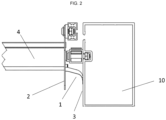
Fig. 2A side view of the tab (1) attached to the header (2) and in contact with the inner face (3) of the beam (10), the movable slat (4) associated to the header (2) is also observed. -
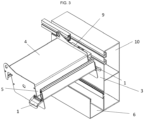
Fig. 3A perspective view of the assembly, wherein one of the beams has been dispensed with, the front one according to the image, to better observe the elements, where the arrangement of the tab (1), the water channel (5) of one of the movable slats (4), a flap (9) of the slat, in this case an extension of the header, which protrudes by way of a flange and carries the water towards the water channel, wherefrom the water passes to the tab (1) that bridges the distance between the water channel and the inner side (3) of the beam (10), channelling and enabling the passage of the water towards a gutter (6) disposed one level lower than the tabs (1). -
Fig. 4A possible embodiment of the invention is observed where the tab (1) has longitudinal grooves (7) that collaborate to direct the passage of the water, and flanges (8) that channel the water avoiding overflows. - An embodiment of the invention is proposed here that is neither unique nor limiting, but merely explanatory.
- The invention relates to an anti-splash device arranged in a pergola of movable slats, where it is common to find a frame comprising pillars and beams where the latter have supports for the bushings housing the shafts of the movable slats.
- The movable slats (4) have at their ends headers that close the piece laterally, the slat shaft being supported by the headers. The device comprises a tab (1) between the header (2) and the inner face (3) of the beam (10), bridging the distance between them.
- The tab (1) is made of flexible material, and presses against the inner side (3) of the beam (10).
- Each movable slat has a water channel (5) which is the longitudinal channel that collects all the rain water falling on the movable slats and directs it towards at least one of the ends of said slats.
- The tab (1) is located at the outlet of the water channel and bridges the distance between the slat, in particular from the header (2) and the inner face (3) of the beam and directs the water from the water channel against that inner face of the beam.
- In this way, the water that falls on the moving slats (4) runs through the water channel (5) towards the tab (1) where it runs towards the inner face (3) of the beam, falling against it and breaking the surface tension of the water that, due to capillarity, runs down the inner face (3) of the beam towards a gutter (6) located at a level lower than the tab (1). This gutter (6) runs longitudinally along the inner face (3) of the beam (10), at least from the point where the tab is located, to a drain such that water falling into the gutter is carried to a drain, preferably arranged in the pillars thus preventing generating splashes inside the enclosure.
- The tab (1) has a convex curved shape on a slope that goes from its highest point at the outlet of the water channel (5) of each of the slats to its lowest point which is the point of contact with the inner face (3) of the beam. In a possible embodiment, the grooves (7) on its top face facing downstream allow the water to be directed uniformly.
- The tab (1) further comprises flanges (8) that prevent water from overflowing and falling directly into the gutter (6) causing splashes inside the enclosure.
- In the water path from the time it impacts the slats (4) passing over the tab (1) to the gutter (6), a constant contact of the water is maintained with all the surfaces it crosses, avoiding unwanted drips and splashes.
- The slats have, at their ends, at their top part, fins (9) that act as barriers. These fins are preferably an extension of the headers, which act by preventing water from the top part of the slat from falling freely over its ends. To do this, these fins carry the water towards the water channel (5).
- The tab is fixed to the slat through removable means, such as screws, which allows on the one hand its mounting at the time of construction of the assembly or its inclusion at a later time, in the same way as it that allows the maintenance and easy replacement of a tab that may have been damaged.
Claims (10)
- ANTI-SPLASH DEVICE FOR PERGOLAS with a structure comprising pillars, beams (10) and slats (4) closed at their ends by headers (2) the slats being arranged between the beams and resting thereon characterised in that it comprises;a. A water channel (5) in each slat that runs longitudinally along the slat and is suitable for collecting the water that falls on the slat and that has an outlet at at least one of its ends.b. A tab (1) arranged at the outlet of the water channel (5) and bridging the distance between the header (2) that closes the slat and the inner face (3) of the beam (10), said tab having a higher end attached to the slat and the other lower end in contact with the inner face (3) of the beam.c. A lower gutter (6) arranged in the vertical of the lowest end of the tab.d. Fins (9) at the ends of the slats.
- ANTI-SPLASH DEVICE FOR PERGOLAS according to claim 1, characterised in that the slats are movable.
- ANTI-SPLASH DEVICE FOR PERGOLAS according to claim 1, characterised in that the tab is flexible and its lower end presses against the inner face (3) of the beam.
- ANTI-SPLASH DEVICE FOR PERGOLAS according to claim 1, characterised in that the tab comprises flanges (8) on its sides.
- ANTI-SPLASH DEVICE FOR PERGOLAS according to claim 1, characterised in that the tab (1) is removably attached to the slat.
- ANTI-SPLASH DEVICE FOR PERGOLAS according to claim 1, characterised in that the tab (1) has a downward convex curved shape from the outlet of the water channel to the inner face of the beam.
- ANTI-SPLASH DEVICE FOR PERGOLAS according to claim 1, characterised in that the tab (1) comprises a plurality of grooves (7) on its upper face facing downstream.
- ANTI-SPLASH DEVICE FOR PERGOLAS according to claim 1, characterised in that the fins (9) are upper extensions of closing headers (2).
- ANTI-SPLASH DEVICE FOR PERGOLAS according to claim 1, characterised in that the gutter (6) runs longitudinally along the inner face (3) of the beam (10).
- ANTI-SPLASH DEVICE FOR PERGOLAS according to claim 1, characterised in that the gutter (6) runs longitudinally along the inner face (3) of the beam (10) from the point where the tab is located to a drain.
Applications Claiming Priority (1)
| Application Number | Priority Date | Filing Date | Title |
|---|---|---|---|
| ES202132007U ES1283794Y (en) | 2021-10-11 | 2021-10-11 | ANTI-SPLASH DEVICE FOR PERGOLAS |
Publications (2)
| Publication Number | Publication Date |
|---|---|
| EP4163450A1 true EP4163450A1 (en) | 2023-04-12 |
| EP4163450B1 EP4163450B1 (en) | 2025-06-25 |
Family
ID=78822216
Family Applications (1)
| Application Number | Title | Priority Date | Filing Date |
|---|---|---|---|
| EP22200661.1A Active EP4163450B1 (en) | 2021-10-11 | 2022-10-10 | Anti-splash device for pergolas |
Country Status (3)
| Country | Link |
|---|---|
| EP (1) | EP4163450B1 (en) |
| ES (2) | ES1283794Y (en) |
| PT (1) | PT4163450T (en) |
Citations (6)
| Publication number | Priority date | Publication date | Assignee | Title |
|---|---|---|---|---|
| WO2002092938A1 (en) | 2001-05-11 | 2002-11-21 | Uwe Spicker | Roofing with adjustable spring supporting shafts |
| EP2589720A1 (en) | 2011-11-07 | 2013-05-08 | Biossun | Anti-drip adjustable slat for protective roof |
| WO2014136095A1 (en) | 2013-03-08 | 2014-09-12 | Renson Sunprotection-Screens Nv | Lamellar roof |
| FR3055637A1 (en) * | 2016-09-05 | 2018-03-09 | Henri Peuchot Alain | PERGOLA COMPRISING AT LEAST ONE ESSENTIALLY RECTANGULAR FRAME AND A PLURALITY OF BLADES |
| ES1208711U (en) | 2017-07-26 | 2018-03-28 | C3 Systems, S.L. | STRUCTURE WITH UPPER CLOSURE AND WATER PICKER PROFILE (Machine-translation by Google Translate, not legally binding) |
| US20210198896A1 (en) * | 2019-12-30 | 2021-07-01 | Yardistry Limited | Louver system and method of assembling same |
-
2021
- 2021-10-11 ES ES202132007U patent/ES1283794Y/en active Active
-
2022
- 2022-10-10 PT PT222006611T patent/PT4163450T/en unknown
- 2022-10-10 EP EP22200661.1A patent/EP4163450B1/en active Active
- 2022-10-10 ES ES22200661T patent/ES3042407T3/en active Active
Patent Citations (6)
| Publication number | Priority date | Publication date | Assignee | Title |
|---|---|---|---|---|
| WO2002092938A1 (en) | 2001-05-11 | 2002-11-21 | Uwe Spicker | Roofing with adjustable spring supporting shafts |
| EP2589720A1 (en) | 2011-11-07 | 2013-05-08 | Biossun | Anti-drip adjustable slat for protective roof |
| WO2014136095A1 (en) | 2013-03-08 | 2014-09-12 | Renson Sunprotection-Screens Nv | Lamellar roof |
| FR3055637A1 (en) * | 2016-09-05 | 2018-03-09 | Henri Peuchot Alain | PERGOLA COMPRISING AT LEAST ONE ESSENTIALLY RECTANGULAR FRAME AND A PLURALITY OF BLADES |
| ES1208711U (en) | 2017-07-26 | 2018-03-28 | C3 Systems, S.L. | STRUCTURE WITH UPPER CLOSURE AND WATER PICKER PROFILE (Machine-translation by Google Translate, not legally binding) |
| US20210198896A1 (en) * | 2019-12-30 | 2021-07-01 | Yardistry Limited | Louver system and method of assembling same |
Also Published As
| Publication number | Publication date |
|---|---|
| ES3042407T3 (en) | 2025-11-20 |
| ES1283794U (en) | 2021-12-13 |
| PT4163450T (en) | 2025-10-01 |
| EP4163450B1 (en) | 2025-06-25 |
| ES1283794Y (en) | 2022-03-04 |
Similar Documents
| Publication | Publication Date | Title |
|---|---|---|
| AU2020203289B2 (en) | Louver Canopy | |
| KR100256323B1 (en) | Flush toilet bowl | |
| CA1092425A (en) | Drainable blade louver | |
| EP4163450B1 (en) | Anti-splash device for pergolas | |
| US4310993A (en) | Louver assembly | |
| GB2132657A (en) | A screen device for a drainage system | |
| GB2277460A (en) | Screen grid for overflow tanks | |
| CN110939254A (en) | Wind cap | |
| KR101183561B1 (en) | Ventilating control system for a roof | |
| US20110265390A1 (en) | Eavestrough cover | |
| JP6101913B2 (en) | Drainer cover and solar cell device | |
| JPH0142578Y2 (en) | ||
| JP7509207B2 (en) | Buildings and drainage | |
| KR101158808B1 (en) | Ventilating control system for a roof | |
| US3352077A (en) | Water seal for roof construction | |
| CN210032867U (en) | Louver canopy | |
| KR20110103705A (en) | Drainage guide | |
| HRP20250574T1 (en) | WATER GASKET FOR DRAINING CHANNELS IN THE AREA OF THE WALL FRAME OF THE BUILDING | |
| JPH05156763A (en) | Double eaves gutter structure | |
| JP3731124B2 (en) | Snowfall prevention device | |
| AU2012233047B2 (en) | Roofing panel water diverting structure | |
| JP6332973B2 (en) | Rain gutters and outdoor structures | |
| EP4603657A1 (en) | Covering apparatus | |
| JP3231633B2 (en) | Sliding door frame | |
| JP4909028B2 (en) | Louver and louvered duct |
Legal Events
| Date | Code | Title | Description |
|---|---|---|---|
| PUAI | Public reference made under article 153(3) epc to a published international application that has entered the european phase |
Free format text: ORIGINAL CODE: 0009012 |
|
| STAA | Information on the status of an ep patent application or granted ep patent |
Free format text: STATUS: THE APPLICATION HAS BEEN PUBLISHED |
|
| AK | Designated contracting states |
Kind code of ref document: A1 Designated state(s): AL AT BE BG CH CY CZ DE DK EE ES FI FR GB GR HR HU IE IS IT LI LT LU LV MC ME MK MT NL NO PL PT RO RS SE SI SK SM TR |
|
| RIN1 | Information on inventor provided before grant (corrected) |
Inventor name: IZQUIERDO ZARAGOZA, ELIAS |
|
| STAA | Information on the status of an ep patent application or granted ep patent |
Free format text: STATUS: REQUEST FOR EXAMINATION WAS MADE |
|
| 17P | Request for examination filed |
Effective date: 20231010 |
|
| RBV | Designated contracting states (corrected) |
Designated state(s): AL AT BE BG CH CY CZ DE DK EE ES FI FR GB GR HR HU IE IS IT LI LT LU LV MC ME MK MT NL NO PL PT RO RS SE SI SK SM TR |
|
| GRAP | Despatch of communication of intention to grant a patent |
Free format text: ORIGINAL CODE: EPIDOSNIGR1 |
|
| STAA | Information on the status of an ep patent application or granted ep patent |
Free format text: STATUS: GRANT OF PATENT IS INTENDED |
|
| INTG | Intention to grant announced |
Effective date: 20250117 |
|
| GRAS | Grant fee paid |
Free format text: ORIGINAL CODE: EPIDOSNIGR3 |
|
| GRAA | (expected) grant |
Free format text: ORIGINAL CODE: 0009210 |
|
| STAA | Information on the status of an ep patent application or granted ep patent |
Free format text: STATUS: THE PATENT HAS BEEN GRANTED |
|
| AK | Designated contracting states |
Kind code of ref document: B1 Designated state(s): AL AT BE BG CH CY CZ DE DK EE ES FI FR GB GR HR HU IE IS IT LI LT LU LV MC ME MK MT NL NO PL PT RO RS SE SI SK SM TR |
|
| REG | Reference to a national code |
Ref country code: GB Ref legal event code: FG4D |
|
| REG | Reference to a national code |
Ref country code: CH Ref legal event code: EP |
|
| REG | Reference to a national code |
Ref country code: DE Ref legal event code: R096 Ref document number: 602022016372 Country of ref document: DE |
|
| REG | Reference to a national code |
Ref country code: CH Ref legal event code: EP |
|
| REG | Reference to a national code |
Ref country code: IE Ref legal event code: FG4D |
|
| REG | Reference to a national code |
Ref country code: PT Ref legal event code: SC4A Ref document number: 4163450 Country of ref document: PT Date of ref document: 20251001 Kind code of ref document: T Free format text: AVAILABILITY OF NATIONAL TRANSLATION Effective date: 20250924 |
|
| PG25 | Lapsed in a contracting state [announced via postgrant information from national office to epo] |
Ref country code: FI Free format text: LAPSE BECAUSE OF FAILURE TO SUBMIT A TRANSLATION OF THE DESCRIPTION OR TO PAY THE FEE WITHIN THE PRESCRIBED TIME-LIMIT Effective date: 20250625 |
|
| PGFP | Annual fee paid to national office [announced via postgrant information from national office to epo] |
Ref country code: PT Payment date: 20250926 Year of fee payment: 4 |
|
| REG | Reference to a national code |
Ref country code: LT Ref legal event code: MG9D |
|
| PG25 | Lapsed in a contracting state [announced via postgrant information from national office to epo] |
Ref country code: NO Free format text: LAPSE BECAUSE OF FAILURE TO SUBMIT A TRANSLATION OF THE DESCRIPTION OR TO PAY THE FEE WITHIN THE PRESCRIBED TIME-LIMIT Effective date: 20250925 |
|
| PG25 | Lapsed in a contracting state [announced via postgrant information from national office to epo] |
Ref country code: BG Free format text: LAPSE BECAUSE OF FAILURE TO SUBMIT A TRANSLATION OF THE DESCRIPTION OR TO PAY THE FEE WITHIN THE PRESCRIBED TIME-LIMIT Effective date: 20250625 |
|
| PG25 | Lapsed in a contracting state [announced via postgrant information from national office to epo] |
Ref country code: HR Free format text: LAPSE BECAUSE OF FAILURE TO SUBMIT A TRANSLATION OF THE DESCRIPTION OR TO PAY THE FEE WITHIN THE PRESCRIBED TIME-LIMIT Effective date: 20250625 |
|
| PGFP | Annual fee paid to national office [announced via postgrant information from national office to epo] |
Ref country code: FR Payment date: 20250917 Year of fee payment: 4 |
|
| PG25 | Lapsed in a contracting state [announced via postgrant information from national office to epo] |
Ref country code: RS Free format text: LAPSE BECAUSE OF FAILURE TO SUBMIT A TRANSLATION OF THE DESCRIPTION OR TO PAY THE FEE WITHIN THE PRESCRIBED TIME-LIMIT Effective date: 20250925 |
|
| PG25 | Lapsed in a contracting state [announced via postgrant information from national office to epo] |
Ref country code: LV Free format text: LAPSE BECAUSE OF FAILURE TO SUBMIT A TRANSLATION OF THE DESCRIPTION OR TO PAY THE FEE WITHIN THE PRESCRIBED TIME-LIMIT Effective date: 20250625 |
|
| REG | Reference to a national code |
Ref country code: NL Ref legal event code: MP Effective date: 20250625 |
|
| REG | Reference to a national code |
Ref country code: GR Ref legal event code: EP Ref document number: 20250401926 Country of ref document: GR Effective date: 20251009 |
|
| P01 | Opt-out of the competence of the unified patent court (upc) registered |
Free format text: CASE NUMBER: UPC_APP_7921_4163450/2025 Effective date: 20250925 |
|
| PG25 | Lapsed in a contracting state [announced via postgrant information from national office to epo] |
Ref country code: NL Free format text: LAPSE BECAUSE OF FAILURE TO SUBMIT A TRANSLATION OF THE DESCRIPTION OR TO PAY THE FEE WITHIN THE PRESCRIBED TIME-LIMIT Effective date: 20250625 |
|
| REG | Reference to a national code |
Ref country code: ES Ref legal event code: FG2A Ref document number: 3042407 Country of ref document: ES Kind code of ref document: T3 Effective date: 20251120 |
|
| REG | Reference to a national code |
Ref country code: AT Ref legal event code: MK05 Ref document number: 1806572 Country of ref document: AT Kind code of ref document: T Effective date: 20250625 |
|
| PG25 | Lapsed in a contracting state [announced via postgrant information from national office to epo] |
Ref country code: IS Free format text: LAPSE BECAUSE OF FAILURE TO SUBMIT A TRANSLATION OF THE DESCRIPTION OR TO PAY THE FEE WITHIN THE PRESCRIBED TIME-LIMIT Effective date: 20251025 |
|
| PG25 | Lapsed in a contracting state [announced via postgrant information from national office to epo] |
Ref country code: AT Free format text: LAPSE BECAUSE OF FAILURE TO SUBMIT A TRANSLATION OF THE DESCRIPTION OR TO PAY THE FEE WITHIN THE PRESCRIBED TIME-LIMIT Effective date: 20250625 Ref country code: SM Free format text: LAPSE BECAUSE OF FAILURE TO SUBMIT A TRANSLATION OF THE DESCRIPTION OR TO PAY THE FEE WITHIN THE PRESCRIBED TIME-LIMIT Effective date: 20250625 |
|
| PGFP | Annual fee paid to national office [announced via postgrant information from national office to epo] |
Ref country code: IT Payment date: 20251031 Year of fee payment: 4 |
|
| PGFP | Annual fee paid to national office [announced via postgrant information from national office to epo] |
Ref country code: GR Payment date: 20251020 Year of fee payment: 4 |
|
| PG25 | Lapsed in a contracting state [announced via postgrant information from national office to epo] |
Ref country code: CZ Free format text: LAPSE BECAUSE OF FAILURE TO SUBMIT A TRANSLATION OF THE DESCRIPTION OR TO PAY THE FEE WITHIN THE PRESCRIBED TIME-LIMIT Effective date: 20250625 |
|
| PG25 | Lapsed in a contracting state [announced via postgrant information from national office to epo] |
Ref country code: PL Free format text: LAPSE BECAUSE OF FAILURE TO SUBMIT A TRANSLATION OF THE DESCRIPTION OR TO PAY THE FEE WITHIN THE PRESCRIBED TIME-LIMIT Effective date: 20250625 |
|
| PG25 | Lapsed in a contracting state [announced via postgrant information from national office to epo] |
Ref country code: EE Free format text: LAPSE BECAUSE OF FAILURE TO SUBMIT A TRANSLATION OF THE DESCRIPTION OR TO PAY THE FEE WITHIN THE PRESCRIBED TIME-LIMIT Effective date: 20250625 |
|
| PG25 | Lapsed in a contracting state [announced via postgrant information from national office to epo] |
Ref country code: SK Free format text: LAPSE BECAUSE OF FAILURE TO SUBMIT A TRANSLATION OF THE DESCRIPTION OR TO PAY THE FEE WITHIN THE PRESCRIBED TIME-LIMIT Effective date: 20250625 |
|
| PGFP | Annual fee paid to national office [announced via postgrant information from national office to epo] |
Ref country code: ES Payment date: 20251117 Year of fee payment: 4 |
|
| PG25 | Lapsed in a contracting state [announced via postgrant information from national office to epo] |
Ref country code: RO Free format text: LAPSE BECAUSE OF FAILURE TO SUBMIT A TRANSLATION OF THE DESCRIPTION OR TO PAY THE FEE WITHIN THE PRESCRIBED TIME-LIMIT Effective date: 20250625 |
|
| PG25 | Lapsed in a contracting state [announced via postgrant information from national office to epo] |
Ref country code: DK Free format text: LAPSE BECAUSE OF FAILURE TO SUBMIT A TRANSLATION OF THE DESCRIPTION OR TO PAY THE FEE WITHIN THE PRESCRIBED TIME-LIMIT Effective date: 20250625 |
|
| PLBE | No opposition filed within time limit |
Free format text: ORIGINAL CODE: 0009261 |
|
| STAA | Information on the status of an ep patent application or granted ep patent |
Free format text: STATUS: NO OPPOSITION FILED WITHIN TIME LIMIT |
|
| REG | Reference to a national code |
Ref country code: CH Ref legal event code: L10 Free format text: ST27 STATUS EVENT CODE: U-0-0-L10-L00 (AS PROVIDED BY THE NATIONAL OFFICE) Effective date: 20260507 |