EP4163438A1 - Guide tube and hyperloop device including same - Google Patents
Guide tube and hyperloop device including same Download PDFInfo
- Publication number
- EP4163438A1 EP4163438A1 EP21821935.0A EP21821935A EP4163438A1 EP 4163438 A1 EP4163438 A1 EP 4163438A1 EP 21821935 A EP21821935 A EP 21821935A EP 4163438 A1 EP4163438 A1 EP 4163438A1
- Authority
- EP
- European Patent Office
- Prior art keywords
- guide tube
- rail support
- tube
- coupled
- main body
- Prior art date
- Legal status (The legal status is an assumption and is not a legal conclusion. Google has not performed a legal analysis and makes no representation as to the accuracy of the status listed.)
- Granted
Links
Images




Classifications
-
- E—FIXED CONSTRUCTIONS
- E01—CONSTRUCTION OF ROADS, RAILWAYS, OR BRIDGES
- E01B—PERMANENT WAY; PERMANENT-WAY TOOLS; MACHINES FOR MAKING RAILWAYS OF ALL KINDS
- E01B25/00—Tracks for special kinds of railways
- E01B25/30—Tracks for magnetic suspension or levitation vehicles
- E01B25/305—Rails or supporting constructions
-
- B—PERFORMING OPERATIONS; TRANSPORTING
- B60—VEHICLES IN GENERAL
- B60L—PROPULSION OF ELECTRICALLY-PROPELLED VEHICLES; SUPPLYING ELECTRIC POWER FOR AUXILIARY EQUIPMENT OF ELECTRICALLY-PROPELLED VEHICLES; ELECTRODYNAMIC BRAKE SYSTEMS FOR VEHICLES IN GENERAL; MAGNETIC SUSPENSION OR LEVITATION FOR VEHICLES; MONITORING OPERATING VARIABLES OF ELECTRICALLY-PROPELLED VEHICLES; ELECTRIC SAFETY DEVICES FOR ELECTRICALLY-PROPELLED VEHICLES
- B60L13/00—Electric propulsion for monorail vehicles, suspension vehicles or rack railways; Magnetic suspension or levitation for vehicles
- B60L13/04—Magnetic suspension or levitation for vehicles
-
- B—PERFORMING OPERATIONS; TRANSPORTING
- B61—RAILWAYS
- B61B—RAILWAY SYSTEMS; EQUIPMENT THEREFOR NOT OTHERWISE PROVIDED FOR
- B61B13/00—Other railway systems
- B61B13/08—Sliding or levitation systems
-
- B—PERFORMING OPERATIONS; TRANSPORTING
- B61—RAILWAYS
- B61B—RAILWAY SYSTEMS; EQUIPMENT THEREFOR NOT OTHERWISE PROVIDED FOR
- B61B13/00—Other railway systems
- B61B13/10—Tunnel systems
-
- E—FIXED CONSTRUCTIONS
- E01—CONSTRUCTION OF ROADS, RAILWAYS, OR BRIDGES
- E01B—PERMANENT WAY; PERMANENT-WAY TOOLS; MACHINES FOR MAKING RAILWAYS OF ALL KINDS
- E01B25/00—Tracks for special kinds of railways
- E01B25/22—Tracks for railways with the vehicle suspended from rigid supporting rails
- E01B25/24—Supporting rails; Auxiliary balancing rails; Supports or connections for rails
-
- E—FIXED CONSTRUCTIONS
- E01—CONSTRUCTION OF ROADS, RAILWAYS, OR BRIDGES
- E01B—PERMANENT WAY; PERMANENT-WAY TOOLS; MACHINES FOR MAKING RAILWAYS OF ALL KINDS
- E01B25/00—Tracks for special kinds of railways
- E01B25/30—Tracks for magnetic suspension or levitation vehicles
-
- E—FIXED CONSTRUCTIONS
- E01—CONSTRUCTION OF ROADS, RAILWAYS, OR BRIDGES
- E01B—PERMANENT WAY; PERMANENT-WAY TOOLS; MACHINES FOR MAKING RAILWAYS OF ALL KINDS
- E01B2201/00—Fastening or restraining methods
- E01B2201/04—Fastening or restraining methods by bolting, nailing or the like
-
- E—FIXED CONSTRUCTIONS
- E01—CONSTRUCTION OF ROADS, RAILWAYS, OR BRIDGES
- E01B—PERMANENT WAY; PERMANENT-WAY TOOLS; MACHINES FOR MAKING RAILWAYS OF ALL KINDS
- E01B2201/00—Fastening or restraining methods
- E01B2201/10—Fastening or restraining methods in alternative ways, e.g. glueing, welding, form-fits
Definitions
- the present disclosure relates to a guide tube and a hyperloop device including the same.
- a technology introduced for this purpose is a Hyperloop device.
- a hyperloop device is a system for transferring a moving vehicle by magnetic levitation in a sealed tube at a pressure of about 0.001 atmosphere or less.
- a rail support member a guideway installed in the tube, is required to maintain a straight line since it resists a load of a moving vehicle and guides the moving vehicle. That is, if the rail support member does not maintain a constant displacement tolerance (about 2 mm or less), a problem in which the moving vehicle deviates while driving, or the like, may occur.
- a factor directly affecting straightening of the rail support member includes deflection caused by a tube's own weight and the moving vehicle, and driving deflection caused by vibrations generated during driving of the moving vehicle.
- an installation position of the rail support member should be adjusted to compensate for deflection caused by the tube's own weight and deflection caused by the moving vehicle at the beginning, and rigidity of the tube should be sufficiently secured to resist vibration.
- Such a conventional method is configured to form a supporting point by making a through-hole in the tube to compensate for the initial deflection of the rail support member, connecting a bolt member to the through-hole, and then welding the same.
- a method of coupling the rail support member to the bolt member is used.
- this conventional method has a limitation in that it is necessary to form a through-hole in the tube, insert a bolt member thereinto, and then weld to fill a remaining portion of the through-hole.
- Such a drilling operation of the through-hole is costly and time-consuming, and in particular, there is a difficulty in forming the through-hole obliquely in the tube so that the through-hole is horizontal with the moving vehicle rather than in a circumferential direction of the tube.
- An aspect of the present disclosure is to provide a guide tube for facilitating installation of a rail support member and a hyperloop device including the same.
- Another aspect of the present disclosure is to provide a guide tube capable of improving a problem of deflection caused by an own weight of a tube main body member or vibration of a moving vehicle, and a hyperloop device including the same.
- a guide tube may include: a tube main body member; a rib member arranged in a longitudinal direction of the tube main body member, and coupled to an inner surface of the tube main body member; and a rail support member connected to the rib member.
- the rib member of the guide tube may be welded and coupled to the tube main body member made of a metal material formed in a tube shape.
- the rib member of the guide tube may include a coupling tab portion formed to protrude in a direction of an inner surface of the tube main body member, provided in plural in a longitudinal direction of the tube main body member, and welded and coupled to the inner surface of the tube main body member.
- the rib member of the guide tube may include a friction damper portion having a slit hole, to which the rail support member is fitted and is connected to a portion of the slit hole, formed therein, so as to absorb vibration energy of the rail support member.
- the slit hole of the guide tube may be in frictional contact with the rail support member.
- the slit hole of the guide tube may be formed in a horizontal shape or an inclined shape to a width direction of the rib member.
- the friction damper portion of the guide tube may include a buffer spring provided in at least one end portion of the slit hole.
- the rail support member of the guide tube may include an insertion tab portion fitted to the slit hole, and a stopper portion protruding in at least one direction of the insertion tab portion to form a step portion.
- the rail support member of the guide tube may be screwed and coupled to a bolt member, screwed and coupled or welded and coupled to the rib member, to be connected to the rib member via the bolt member.
- the rail support member of the guide tube may adjust a depth to be screwed and coupled to the bolt member, to adjust a spacing with the rib member.
- a hyperloop device may include: the guide tube, an electromagnet member coupled to the guide tube and the rail support member; and a moving vehicle having a permanent magnet facing the electromagnet member, a transport of the moving vehicle being adjusted by magnetic force applied between the electromagnet member and the permanent magnet, and having an accommodation space formed therein.
- a guide tube and a hyperloop device including the same have an advantage of being able to facilitate installation of a rail support member.
- the guide tube and the hyperloop device including the same of the present disclosure have an advantage of improving a problem of deflection caused by an own weight of a tube main body member or vibrations of a moving vehicle.
- the present disclosure relates to a guide tube 1 and a hyperloop device including the same, and a rail support member 30 may be easily installed therein. That is, since a rib member 20 having the rail support member 30 installed is coupled to an inner surface of a tube main body member 10 without forming a through-hole on the tube main body member 10, the rail support member 30 may be easily installed.
- the guide tube 1 and the hyperloop device including the same may improve a problem of deflection caused by the own weight of the tube main body member 10, vibration of a moving vehicle 3, or the like. That is, it is possible to improve a problem in which the tube main body member 10 is deflected by the rib member 20 disposed in a longitudinal direction of the tube main body member 10.
- a friction damper portion 22 may be provided to absorb vibration as frictional force, thereby improving the problem of deflection of the tube main body member 10 due to vibration.
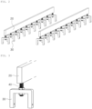
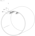
- FIG. 1 is a perspective view illustrating a guide tube 1 of the present disclosure
- FIG. 2 is a perspective view illustrating a rib member 20 and a rail support member 30 in the guide tube 1 of the present disclosure
- FIG. 3 is a perspective view illustrating a rail support member 30 coupled to the rib member 20 via a bolt member 40 in the guide tube 1 of the present disclosure.
- the guide tube 1 may include a tube main body member 10, a rib member 20, and a rail support member 30.
- the rib member 20 may be disposed in a longitudinal direction of the tube main body member 10, and may be coupled to the inner surface of the tube main body member 10.
- the rail support member 30 may be connected to the rib member 20.
- the rib member 20 is disposed and coupled in the longitudinal direction of the tube main body member 10, it also serves to support the tube main body member 10 in the length direction thereof.
- FIG. 12 is a simulation result illustrating a comparison of deflection deformation of the conventional tube and the guide tube 1 of the present disclosure
- FIG. 12(a) illustrates a conventional form
- FIG. 12(b) illustrates the guide tube 1 of the present disclosure.
- the rail support member 30 can be installed in the rib member 20 without forming a through-hole in the tube main body member 10, it is possible to reduce a cost as the through-hole is formed obliquely in the tube main body member 10, and in addition, a problem in which an inside of the tube main body member 10 may not be ensured to be in a sub-vacuum state of about 0.001 atmosphere or less depending on reliability of a filling operation of the through-hole, since the operation for filling the through-hole is unnecessary.
- the rib member 20 of the guide tube 1 may be welded and coupled to the tube main body member 10 made of a metal material formed in a tube shape.
- the rib member 20 may be coupled thereto through direct welding without forming a separate through-hole for coupling to the inner surface of the tube main body member 10.
- FIG. 4 is a partially cut cross-sectional view illustrating a rib member 20 and a rail support member 30 coupled to a bolt member 40 in the guide tube 1 of the present disclosure.
- the rail support member 30 of the guide tube 1 may be screwed and coupled to a bolt member 40, screwed and coupled or welded and coupled to the rib member 20, and connected to the rib member 20 via the bolt member 40.
- the rail support member 30 may be coupled to the rib member 20 coupled to the tube main body member 10.
- the bolt member 40 may be welded and coupled to the rib member 20, but may be screwed and coupled, to adjust a spacing therebetween while coupled to the rib member 20. As a result, the spacing between the rail support member 30 and the rib member 20 may be adjusted.
- the rail support member 30 of the guide tube 1 may adjust a depth to be screwed and coupled to the bolt member 40, to adjust the spacing with the rib member 20.
- adjustment of the spacing between the rail support member 30 and the rib member 20 may be performed by adjusting a degree of coupling between the rib member 20 and the bolt member 40, but also by adjusting a degree of coupling between the rail support member 30 and the bolt member 40.
- FIG. 5 is a perspective view illustrating an embodiment in which a rib member 20 includes a coupling tab portion 21 in the guide tube 1 of the present disclosure
- FIG. 6 is a perspective view illustrating a state in which a rib member 20 including a coupling tab portion 21 is coupled to a tube main body member 10 in the guide tube 1 of the present disclosure.
- the rib member 20 of the guide tube 1 may include a coupling tab portion 21.
- the coupling tab portion 21 is formed to protrude in a direction of an inner surface of the tube main body member 10, is provided in plural in a longitudinal direction of the tube main body member 10, and is welded and coupled to the inner surface of the tube main body member 10.
- the rib member 20 is coupled to the tube main body member 10 through the coupling tab portion 21, it is possible to reduce a welding coupling portion when being welded and coupled to the tube main body member 10, so that a coupling operation may be easily performed.
- FIG. 7 is a perspective view illustrating an embodiment in which a rib member 20 includes a friction damper portion 22 in the guide tube 1 of the present disclosures
- FIG. 8 is a perspective view illustrating an operating state of the friction damper portion 22 in the guide tube 1 of the present disclosure.
- the rib member 20 of the guide tube 1 may include a friction damper portion 22.
- the friction damper portion 22 may have a slit hole 22a in which the rail support member 30 is fitted to a portion of the slit hole and is connected, to absorb vibration energy of the rail support member 30.
- the friction damper portion 22 may dissipate vibration energy generated by the moving vehicle 3, external factors, and the like, as the friction damper portion 22 supports to move the rail support member 30 in a slit hole 22a shape direction.
- the friction damper portion 22 uses frictional force acting between the rail support member 30 and the rail support member 30 as resistive force to absorb the vibration energy, thereby improving the problem caused by vibration.
- the slit hole22a of the guide tube 1 is in frictional contact with the rail support member 30 to absorb vibration energy.
- the slit hole 22a of the guide tube 1 may be formed in a horizontal shape or an inclined shape in a width direction of the rib member 20.
- a form of the slit hole 22a is not limited to the above-described form, and the slit hole 22a of the present disclosure may be used as long as it can effectively absorb vibration energy.
- a buffer spring 22b may be provided in the slit hole 22a to more effectively absorb vibration energy, and a detailed description thereof will be described with reference to FIG. 9 .
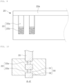
- FIG. 9 is a side view illustrating an embodiment in which a friction damper portion 22 includes a buffer spring 22b in the guide tube 1 of the present disclosure.
- the friction damper portion 22 of the guide tube 1 may include a buffer spring 22b provided in at least one end portion of the slit hole 22a.
- the buffer spring 22b is provided in one end portion in a longitudinal direction of the slit hole22a through which the rail support member 30 moves, the buffer spring 22b is disposed on a path on which the rail support member 30 moves by vibration. Accordingly, an elastic force of the buffer spring 22b becomes a resistive force to buffer the movement caused by the vibration of the rail support member 30, thereby dissipating vibration energy applied to the rail support member 30.
- the vibration energy of the rail support member 30 may be dissipated as elastic energy of the buffer spring 22b in addition to being dissipated as friction energy with the slit hole 22a.
- the rib member 20 may be configured such that an upper end portion of the slit hole22a is opened so that a top portion thereof is separated.
- the rib top portion 20a when the rail support member 30 is fitted to the slit-hole 22a in which an upper end portion thereof is opened, in a state in which a rib top portion 20a, which is a top portion, is separated, the rib top portion 20a may be disposed on the top portion again and coupled by welding, or the like, to be assembled to close the upper end portion of the slit hole 22a.
- the rail support member 30 may include an insertion tab portion 31 and a stopper portion 32, so that a position thereof is not deviated while being moved from the slit hole 22a of the rib member 20 while dissipating vibration energy.
- FIG. 10 is a plan view illustrating a cut section of part A-A' in FIG. 7 .
- the rail support member 30 of the guide tube 1 may include an insertion tab portion 31 and a stopper portion 32.
- the insertion tab portion 31 is configured to be fitted to the slit hole 22a.
- the stopper portion 32 is configured to protrude in at least one direction of the insertion tab portion 31 to form a step portion.
- the insertion tab portion 31 is fitted to the slit hole 22a so that the rail support member 30 moves along the slit hole 22a, and serves to dissipate vibration energy transmitted to the rail support member 30.
- the stopper portion 32 serves to support not to be separated, when the insertion tab portion 31 moves along the slit hole 22a.
- the rail support member 30 is provided in a shape in which a portion of one side of a letter " ⁇ " is opened, and an insertion tab portion 31 is formed to protrude from this broken portion, and a stopper portion 32 may be formed in a form of a step therearound.
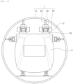
- FIG. 11 is a front view illustrating a guide tube 1 of the present disclosure and a hyperloop device including the same.
- the hyperloop device according to another embodiment of the present disclosure may include the guide tube 1, an electromagnet member 2, and a moving vehicle 3.
- the electromagnet member 2 is configured to be coupled to the rail support member 30.
- the moving vehicle 3 is provided with a permanent magnet 3a facing the electromagnet member 2, and a transport of the moving vehicle 3 is adjusted by magnetic force applied between the electromagnet member 2 and the permanent magnet 3a, and is configured to have an accommodation space formed therein.
- magnetic levitation and movement of the moving vehicle 3 may be performed by an action of mutual attraction and repulsion between the permanent magnet 3a and the electromagnet member 2.
- the electromagnet member 2 may be configured to adjust magnetic force formation by adjusting a current applied to an electrical steel sheet.
Landscapes
- Engineering & Computer Science (AREA)
- Mechanical Engineering (AREA)
- Transportation (AREA)
- Architecture (AREA)
- Civil Engineering (AREA)
- Structural Engineering (AREA)
- Physics & Mathematics (AREA)
- Electromagnetism (AREA)
- Power Engineering (AREA)
- Vibration Prevention Devices (AREA)
- Bearings For Parts Moving Linearly (AREA)
- Rigid Pipes And Flexible Pipes (AREA)
- Infusion, Injection, And Reservoir Apparatuses (AREA)
- Endoscopes (AREA)
- Supports For Pipes And Cables (AREA)
Abstract
Description
- The present disclosure relates to a guide tube and a hyperloop device including the same.
- In general, in a high-speed train system, capable of about 300 km/h or more, the issues of two types of resistance should be solved depending on the speed. One is to solve exponentially rising air resistance, and the other is to solve friction between a moving vehicle and a track.
- A technology introduced for this purpose is a Hyperloop device. Such a hyperloop device is a system for transferring a moving vehicle by magnetic levitation in a sealed tube at a pressure of about 0.001 atmosphere or less.
- In such a hyperloop device, while the electromagnetic and mechanical systems are important, it is important to implement a tube structure to maintain a sub-vacuum state of about 0.001 atmosphere or less, accounting for about 50% or more of an initial investment cost.
- In addition, a rail support member, a guideway installed in the tube, is required to maintain a straight line since it resists a load of a moving vehicle and guides the moving vehicle. That is, if the rail support member does not maintain a constant displacement tolerance (about 2 mm or less), a problem in which the moving vehicle deviates while driving, or the like, may occur.
- A factor directly affecting straightening of the rail support member includes deflection caused by a tube's own weight and the moving vehicle, and driving deflection caused by vibrations generated during driving of the moving vehicle.
- In order to control this, an installation position of the rail support member should be adjusted to compensate for deflection caused by the tube's own weight and deflection caused by the moving vehicle at the beginning, and rigidity of the tube should be sufficiently secured to resist vibration.
- Such a conventional method is configured to form a supporting point by making a through-hole in the tube to compensate for the initial deflection of the rail support member, connecting a bolt member to the through-hole, and then welding the same. A method of coupling the rail support member to the bolt member is used.
- However, this conventional method has a limitation in that it is necessary to form a through-hole in the tube, insert a bolt member thereinto, and then weld to fill a remaining portion of the through-hole.
- Such a drilling operation of the through-hole is costly and time-consuming, and in particular, there is a difficulty in forming the through-hole obliquely in the tube so that the through-hole is horizontal with the moving vehicle rather than in a circumferential direction of the tube. In addition, it is necessary to maintain a vacuum state inside the tube by performing infill welding after drilling the through hole, but there is a limit in that the vacuum of the tube cannot be secured depending on the reliability of this operation.
- Therefore, there is a need for research on a guide tube and a hyperloop device including the same to improve the above-described problems or limitations.
- An aspect of the present disclosure is to provide a guide tube for facilitating installation of a rail support member and a hyperloop device including the same.
- Another aspect of the present disclosure is to provide a guide tube capable of improving a problem of deflection caused by an own weight of a tube main body member or vibration of a moving vehicle, and a hyperloop device including the same.
- According to an aspect of the present disclosure, a guide tube, may include: a tube main body member; a rib member arranged in a longitudinal direction of the tube main body member, and coupled to an inner surface of the tube main body member; and a rail support member connected to the rib member.
- The rib member of the guide tube according to an embodiment of the present disclosure may be welded and coupled to the tube main body member made of a metal material formed in a tube shape.
- The rib member of the guide tube according to an embodiment of the present disclosure may include a coupling tab portion formed to protrude in a direction of an inner surface of the tube main body member, provided in plural in a longitudinal direction of the tube main body member, and welded and coupled to the inner surface of the tube main body member.
- The rib member of the guide tube according to an embodiment of the present disclosure may include a friction damper portion having a slit hole, to which the rail support member is fitted and is connected to a portion of the slit hole, formed therein, so as to absorb vibration energy of the rail support member.
- The slit hole of the guide tube according to an embodiment of the present disclosure may be in frictional contact with the rail support member.
- The slit hole of the guide tube according to an embodiment of the present disclosure may be formed in a horizontal shape or an inclined shape to a width direction of the rib member.
- In addition, the friction damper portion of the guide tube according to an embodiment of the present disclosure may include a buffer spring provided in at least one end portion of the slit hole.
- The rail support member of the guide tube according to an embodiment of the present disclosure may include an insertion tab portion fitted to the slit hole, and a stopper portion protruding in at least one direction of the insertion tab portion to form a step portion.
- In addition, the rail support member of the guide tube according to an embodiment of the present disclosure may be screwed and coupled to a bolt member, screwed and coupled or welded and coupled to the rib member, to be connected to the rib member via the bolt member.
- The rail support member of the guide tube according to an embodiment of the present disclosure may adjust a depth to be screwed and coupled to the bolt member, to adjust a spacing with the rib member.
- According to another aspect of the present disclosure, a hyperloop device may include: the guide tube, an electromagnet member coupled to the guide tube and the rail support member; and a moving vehicle having a permanent magnet facing the electromagnet member, a transport of the moving vehicle being adjusted by magnetic force applied between the electromagnet member and the permanent magnet, and having an accommodation space formed therein.
- As set forth above, according to the present disclosure, a guide tube and a hyperloop device including the same have an advantage of being able to facilitate installation of a rail support member.
- In another aspect, the guide tube and the hyperloop device including the same of the present disclosure have an advantage of improving a problem of deflection caused by an own weight of a tube main body member or vibrations of a moving vehicle.
- However, various and beneficial advantages and effects of the present disclosure is not limited to the above, and will be more easily understood in a process of describing specific embodiments of the present disclosure.
-
-
FIG. 1 is a perspective view illustrating a guide tube of the present disclosure. -
FIG. 2 is a perspective view illustrating a rib member, and a rail support member in the guide tube of the present disclosure. -
FIG. 3 is a perspective view illustrating a rail support member coupled to the rib member via a bolt member in the guide tube of the present disclosure. -
FIG. 4 is a partially cut sectional view illustrating the rib member and the rail support member coupled to the bolt member in the guide tube of the present disclosure. -
FIG. 5 is a perspective view illustrating an embodiment in which the rib member includes a coupling tab portion in the guide tube of the present disclosure. -
FIG.6 is a perspective view illustrating a state in which the rib member including the coupling tab portion is coupled to the tube main body member in the guide tube of the present disclosure. -
FIG. 7 is a perspective view illustrating an embodiment in which the rib member includes a friction damper portion in the guide tube of the present disclosure. -
FIG. 8 is a perspective view illustrating an operating state of the friction damper portion in the guide tube of the present disclosure. -
FIG. 9 is a side view illustrating an embodiment in which the friction damper portion includes a buffer spring in the guide tube of the present disclosure. -
FIG. 10 is a plan view illustrating a cut cross-section of portion A-A' inFIG. 7 . -
FIG. 11 is a front view illustrating a guide tube and a hyperloop device including the same of the present disclosure. -
FIG. 12 is a simulation result illustrating a comparison of deflection deformation of the conventional tube and the guide tube of the present disclosure. - Hereinafter, embodiments of the present disclosure will be described as follows with reference to the attached drawings. The present disclosure may, however, be exemplified in many different forms and should not be construed as being limited to the specific embodiments set forth herein. Rather, these embodiments are provided so that this disclosure will be thorough and complete, and will fully convey the scope of the disclosure to those skilled in the art. Accordingly, shapes and sizes of elements in the drawings may be exaggerated for clarity of description, and elements indicated by the same reference numeral are same elements in the drawings.
- In addition, in this specification, the singular expression includes the plural expression unless the context clearly dictates otherwise, and the same reference signs or reference signs assigned in a similar manner throughout the specification refer to the same element or corresponding element.
- The present disclosure relates to a
guide tube 1 and a hyperloop device including the same, and arail support member 30 may be easily installed therein. That is, since arib member 20 having therail support member 30 installed is coupled to an inner surface of a tubemain body member 10 without forming a through-hole on the tubemain body member 10, therail support member 30 may be easily installed. - In another aspect, the
guide tube 1 and the hyperloop device including the same may improve a problem of deflection caused by the own weight of the tubemain body member 10, vibration of a movingvehicle 3, or the like. That is, it is possible to improve a problem in which the tubemain body member 10 is deflected by therib member 20 disposed in a longitudinal direction of the tubemain body member 10. In addition, afriction damper portion 22 may be provided to absorb vibration as frictional force, thereby improving the problem of deflection of the tubemain body member 10 due to vibration. - Specifically, referring to the drawings,
FIG. 1 is a perspective view illustrating aguide tube 1 of the present disclosure, andFIG. 2 is a perspective view illustrating arib member 20 and arail support member 30 in theguide tube 1 of the present disclosure, andFIG. 3 is a perspective view illustrating arail support member 30 coupled to therib member 20 via abolt member 40 in theguide tube 1 of the present disclosure. Referring to the drawings, theguide tube 1 according to an embodiment of the present disclosure may include a tubemain body member 10, arib member 20, and arail support member 30. - Here, the
rib member 20 may be disposed in a longitudinal direction of the tubemain body member 10, and may be coupled to the inner surface of the tubemain body member 10. Therail support member 30 may be connected to therib member 20. - As described above, since the
rib member 20 is disposed and coupled in the longitudinal direction of the tubemain body member 10, it also serves to support the tubemain body member 10 in the length direction thereof. - Accordingly, it is possible to improve a problem that the tube
main body member 10 is deflected due to inherent weight. This can be confirmed with reference to a simulation result ofFIG. 12 . - That is,
FIG. 12 is a simulation result illustrating a comparison of deflection deformation of the conventional tube and theguide tube 1 of the present disclosure, andFIG. 12(a) illustrates a conventional form, andFIG. 12(b) illustrates theguide tube 1 of the present disclosure. - Here, in a case of prior art, deflection of 0.52 mm occurs at an upper end, but the
guide tube 1 of the present disclosure deflects only by 0.49 mm, so it can be seen that there is an effect of improving a problem of deflection by about 6%, compared to the prior art. - In addition, in the case of the prior art, 0.20 mm of deflection occurs at a lower end, but the
guide tube 1 of the present disclosure has only 0.19 mm deflection, so it can be seen that there is an effect of improving the problem of deflection by about 5%, as compared to the prior art. - As described above, in the
guide tube 1 of the present disclosure, since therail support member 30 can be installed in therib member 20 without forming a through-hole in the tubemain body member 10, it is possible to reduce a cost as the through-hole is formed obliquely in the tubemain body member 10, and in addition, a problem in which an inside of the tubemain body member 10 may not be ensured to be in a sub-vacuum state of about 0.001 atmosphere or less depending on reliability of a filling operation of the through-hole, since the operation for filling the through-hole is unnecessary. - Here, the
rib member 20 of theguide tube 1 according to an embodiment of the present disclosure may be welded and coupled to the tubemain body member 10 made of a metal material formed in a tube shape. In other words, therib member 20 may be coupled thereto through direct welding without forming a separate through-hole for coupling to the inner surface of the tubemain body member 10. -
FIG. 4 is a partially cut cross-sectional view illustrating arib member 20 and arail support member 30 coupled to abolt member 40 in theguide tube 1 of the present disclosure. Referring toFIG. 4 , therail support member 30 of theguide tube 1 according to an embodiment of the present disclosure may be screwed and coupled to abolt member 40, screwed and coupled or welded and coupled to therib member 20, and connected to therib member 20 via thebolt member 40. - That is, as the
rail support member 30 is coupled to thebolt member 40 provided in therib member 20, therail support member 30 may be coupled to therib member 20 coupled to the tubemain body member 10. - Here, the
bolt member 40 may be welded and coupled to therib member 20, but may be screwed and coupled, to adjust a spacing therebetween while coupled to therib member 20. As a result, the spacing between therail support member 30 and therib member 20 may be adjusted. - In addition, the
rail support member 30 of theguide tube 1 according to an embodiment of the present disclosure may adjust a depth to be screwed and coupled to thebolt member 40, to adjust the spacing with therib member 20. - That is, adjustment of the spacing between the
rail support member 30 and therib member 20 may be performed by adjusting a degree of coupling between therib member 20 and thebolt member 40, but also by adjusting a degree of coupling between therail support member 30 and thebolt member 40. -
FIG. 5 is a perspective view illustrating an embodiment in which arib member 20 includes acoupling tab portion 21 in theguide tube 1 of the present disclosure, andFIG. 6 is a perspective view illustrating a state in which arib member 20 including acoupling tab portion 21 is coupled to a tubemain body member 10 in theguide tube 1 of the present disclosure. Referring to the drawings, therib member 20 of theguide tube 1 according to an embodiment of the present disclosure may include acoupling tab portion 21. - Here, the
coupling tab portion 21 is formed to protrude in a direction of an inner surface of the tubemain body member 10, is provided in plural in a longitudinal direction of the tubemain body member 10, and is welded and coupled to the inner surface of the tubemain body member 10. - As described above, since the
rib member 20 is coupled to the tubemain body member 10 through thecoupling tab portion 21, it is possible to reduce a welding coupling portion when being welded and coupled to the tubemain body member 10, so that a coupling operation may be easily performed. -
FIG. 7 is a perspective view illustrating an embodiment in which arib member 20 includes afriction damper portion 22 in theguide tube 1 of the present disclosures, andFIG. 8 is a perspective view illustrating an operating state of thefriction damper portion 22 in theguide tube 1 of the present disclosure. Referring to the drawings, therib member 20 of theguide tube 1 according to an embodiment of the present disclosure may include afriction damper portion 22. - Here, the
friction damper portion 22 may have aslit hole 22a in which therail support member 30 is fitted to a portion of the slit hole and is connected, to absorb vibration energy of therail support member 30. - That is, the
friction damper portion 22 may dissipate vibration energy generated by the movingvehicle 3, external factors, and the like, as thefriction damper portion 22 supports to move therail support member 30 in aslit hole 22a shape direction. - In particular, the
friction damper portion 22 uses frictional force acting between therail support member 30 and therail support member 30 as resistive force to absorb the vibration energy, thereby improving the problem caused by vibration. - That is, the slit hole22a of the
guide tube 1 according to an embodiment of the present disclosure is in frictional contact with therail support member 30 to absorb vibration energy. - Here, the
slit hole 22a of theguide tube 1 according to an embodiment of the present disclosure may be formed in a horizontal shape or an inclined shape in a width direction of therib member 20. - A form of the
slit hole 22a is not limited to the above-described form, and theslit hole 22a of the present disclosure may be used as long as it can effectively absorb vibration energy. - In addition, a
buffer spring 22b may be provided in theslit hole 22a to more effectively absorb vibration energy, and a detailed description thereof will be described with reference toFIG. 9 . -
FIG. 9 is a side view illustrating an embodiment in which afriction damper portion 22 includes abuffer spring 22b in theguide tube 1 of the present disclosure. Referring toFIG. 9 , thefriction damper portion 22 of theguide tube 1 according to an embodiment of the present disclosure may include abuffer spring 22b provided in at least one end portion of theslit hole 22a. - That is, since the
buffer spring 22b is provided in one end portion in a longitudinal direction of the slit hole22a through which therail support member 30 moves, thebuffer spring 22b is disposed on a path on which therail support member 30 moves by vibration. Accordingly, an elastic force of thebuffer spring 22b becomes a resistive force to buffer the movement caused by the vibration of therail support member 30, thereby dissipating vibration energy applied to therail support member 30. - In other words, the vibration energy of the
rail support member 30 may be dissipated as elastic energy of thebuffer spring 22b in addition to being dissipated as friction energy with theslit hole 22a. - In order to install the
rail support member 30 to be fitted to thefriction damper portion 22, therib member 20 may be configured such that an upper end portion of the slit hole22a is opened so that a top portion thereof is separated. - That is, in the
rib member 20, when therail support member 30 is fitted to the slit-hole 22a in which an upper end portion thereof is opened, in a state in which arib top portion 20a, which is a top portion, is separated, therib top portion 20a may be disposed on the top portion again and coupled by welding, or the like, to be assembled to close the upper end portion of theslit hole 22a. - In addition, the
rail support member 30 may include aninsertion tab portion 31 and astopper portion 32, so that a position thereof is not deviated while being moved from theslit hole 22a of therib member 20 while dissipating vibration energy. - That is,
FIG. 10 is a plan view illustrating a cut section of part A-A' inFIG. 7 . Referring toFIG. 10 , therail support member 30 of theguide tube 1 according to an embodiment of the present disclosure may include aninsertion tab portion 31 and astopper portion 32. - Here, the
insertion tab portion 31 is configured to be fitted to theslit hole 22a. Thestopper portion 32 is configured to protrude in at least one direction of theinsertion tab portion 31 to form a step portion. - In other words, the
insertion tab portion 31 is fitted to theslit hole 22a so that therail support member 30 moves along theslit hole 22a, and serves to dissipate vibration energy transmitted to therail support member 30. Thestopper portion 32 serves to support not to be separated, when theinsertion tab portion 31 moves along theslit hole 22a. - As showed in
FIG. 10 , therail support member 30 is provided in a shape in which a portion of one side of a letter "□" is opened, and aninsertion tab portion 31 is formed to protrude from this broken portion, and astopper portion 32 may be formed in a form of a step therearound. - In the present disclosure, a hyperloop device provided with the
guide tube 1 described above may be included. That is,FIG. 11 is a front view illustrating aguide tube 1 of the present disclosure and a hyperloop device including the same. Referring toFIG. 11 , the hyperloop device according to another embodiment of the present disclosure may include theguide tube 1, anelectromagnet member 2, and a movingvehicle 3. - Here, the
electromagnet member 2 is configured to be coupled to therail support member 30. The movingvehicle 3 is provided with apermanent magnet 3a facing theelectromagnet member 2, and a transport of the movingvehicle 3 is adjusted by magnetic force applied between theelectromagnet member 2 and thepermanent magnet 3a, and is configured to have an accommodation space formed therein. - As described above, magnetic levitation and movement of the moving
vehicle 3 may be performed by an action of mutual attraction and repulsion between thepermanent magnet 3a and theelectromagnet member 2. - The
electromagnet member 2 may be configured to adjust magnetic force formation by adjusting a current applied to an electrical steel sheet. - Hereinafter, the present disclosure will be described in more detail through examples. However, it should be noted that the following examples are for illustrative purposes only and are not intended to limit the scope of the present disclosure. The scope of the present disclosure may be determined by matters described in the claims and matters able to be reasonably inferred therefrom. The subject of the present invention is not limited to the above. The subject of the present invention will be understood from the overall content of the present specification, and those of ordinary skill in the art to which the present invention pertains will have no difficulty in understanding the additional subject of the present invention.
- While example embodiments have been shown and described above, it will be apparent to those skilled in the art that modifications and variations could be made without departing from the scope of the present disclosure as defined by the appended claims.
- DESCRIPTION OF REFERENCE NUMERALS
1: GUIDE TUBE 2: ELECTROMAGNETIC MEMBER 3: MOVING VEHICLE 10: TUBE MAIN BODY MEMBER 20: RIB MEMBER 21: COUPLING TAB PORTION 22: FRICTION DAMPER PORTION 30: RAIL SUPPORT MEMBER 31: INSERTION TAB PORTION 32: STOPPER PORTION 40: BOLT MEMBER
Claims (11)
- A guide tube, comprising:a tube main body member;a rib member arranged in a longitudinal direction of the tube main body member, and coupled to an inner surface of the tube main body member; anda rail support member connected to the rib member.
- The guide tube of claim 1, wherein the rib member is welded and coupled to the tube main body member formed of a metal material formed in a form of a tube material.
- The guide tube of claim 1, wherein the rib member comprises a coupling tab portion formed to protrude in a direction of the inner surface of the tube main body member, provided in plural in the longitudinal direction of the tube main body member, and welded and coupled to the inner surface of the tube main body member.
- The guide tube of claim 1, wherein the rib member comprises a friction damper portion formed with a slit hole in which the rail support member is insertedly connected to a portion of the slit hole to absorb vibration energy of the rail support member.
- The guide tube of claim 4, wherein the slit hole is in frictional contact with the rail support member.
- The guide tube of claim 5, wherein the slit hole is formed in a horizontal form or an inclined form to a width direction of the rib member.
- The guide tube of claim 4, wherein the friction damper portion comprises a buffer spring provided in at least one end portion of the slit hole.
- The guide tube of claim 4, wherein the rail support member comprisesan insertion tab portion fitted to the slit hole; anda stopper portion protruding in at least one direction of the insertion tab portion to form a stepped portion.
- The guide tube of claim 1, wherein the rail support member is screwed and coupled to a bolt member, screwed and coupled or welded and coupled to the rib member, to be connected to the rib member via the bolt member.
- The guide tube of claim 9, wherein the rail support member is configured to adjust a depth to be screwed and coupled to the bolt member, to adjust a spacing with the rib member.
- A hyperloop device, comprising:the guide tube of any one of claims 1 to 10;an electromagnet member coupled to the rail support member; anda moving vehicle having a permanent magnet facing the electromagnet member, a transport of the moving vehicle being adjusted by magnetic force applied between the electromagnet member and the permanent magnet, and having an accommodation space formed therein.
Applications Claiming Priority (2)
| Application Number | Priority Date | Filing Date | Title |
|---|---|---|---|
| KR1020200068947A KR102386207B1 (en) | 2020-06-08 | 2020-06-08 | Guide tube and hyperloop apparatus having thereof |
| PCT/KR2021/007139 WO2021251722A1 (en) | 2020-06-08 | 2021-06-08 | Guide tube and hyperloop device including same |
Publications (4)
| Publication Number | Publication Date |
|---|---|
| EP4163438A1 true EP4163438A1 (en) | 2023-04-12 |
| EP4163438A4 EP4163438A4 (en) | 2023-11-29 |
| EP4163438C0 EP4163438C0 (en) | 2025-03-05 |
| EP4163438B1 EP4163438B1 (en) | 2025-03-05 |
Family
ID=78846326
Family Applications (1)
| Application Number | Title | Priority Date | Filing Date |
|---|---|---|---|
| EP21821935.0A Active EP4163438B1 (en) | 2020-06-08 | 2021-06-08 | Guide tube and hyperloop device including same |
Country Status (5)
| Country | Link |
|---|---|
| US (1) | US12624505B2 (en) |
| EP (1) | EP4163438B1 (en) |
| KR (1) | KR102386207B1 (en) |
| CN (1) | CN115768951B (en) |
| WO (1) | WO2021251722A1 (en) |
Families Citing this family (2)
| Publication number | Priority date | Publication date | Assignee | Title |
|---|---|---|---|---|
| KR20240035118A (en) | 2022-09-08 | 2024-03-15 | 주식회사 포스코 | Tube Vibration Damping Structure |
| KR20240134423A (en) | 2023-03-02 | 2024-09-10 | 현대로템 주식회사 | Hyperloop with Strake |
Family Cites Families (23)
| Publication number | Priority date | Publication date | Assignee | Title |
|---|---|---|---|---|
| US5282424A (en) * | 1991-11-18 | 1994-02-01 | Neill Gerard K O | High speed transport system |
| JP2515557Y2 (en) * | 1993-06-14 | 1996-10-30 | 株式会社岡村製作所 | Supporting device for traveling rail in article transport device |
| DE19708747A1 (en) * | 1997-02-25 | 1998-09-03 | Mannesmann Ag | Suspension of a rail |
| KR200211870Y1 (en) * | 1998-10-10 | 2001-02-01 | 정훈보 | Angle Frames for Railroad Cars |
| CN1111123C (en) | 2000-04-04 | 2003-06-11 | 李岭群 | Vacuum and permanent magnet compensated pipeline-type hovertrain-overhead railway-station system |
| JP2004083264A (en) * | 2002-08-28 | 2004-03-18 | Toshiba Plant Kensetsu Co Ltd | Beam attaching device |
| DE10257340A1 (en) | 2002-12-06 | 2004-06-24 | Max Bögl Bauunternehmung GmbH & Co. KG | Track for magnetic levitation railway has support brackets attached at intervals to box-section rail with U-section portion accommodating bolts holding stator packets |
| JP5408862B2 (en) | 2007-11-12 | 2014-02-05 | 日華化学株式会社 | Dyeability improver for polyester fiber materials |
| KR101051929B1 (en) | 2009-08-12 | 2011-07-26 | 이익재 | Agitated pipe member for mixing syrup and mix |
| KR20130004264U (en) | 2011-12-30 | 2013-07-10 | 현대중공업 주식회사 | A structure for supporting pipe |
| US9085304B2 (en) * | 2013-03-15 | 2015-07-21 | Daryl Oster | Evacuated tube transport system with improved cooling for superconductive elements |
| EP3253636B1 (en) * | 2015-02-08 | 2021-05-12 | Hyperloop Technologies, Inc. | Transportation system |
| EP3338925A1 (en) | 2016-12-23 | 2018-06-27 | HILTI Aktiengesellschaft | Trepanning drill bit with a spiral-shaped drill shaft and method for producing a spiral-shaped drill shaft for a drill bit |
| KR101781433B1 (en) * | 2017-01-17 | 2017-09-25 | (주)융도엔지니어링 | Base isolated connecting unit for ceiling equipment |
| CN108372864B (en) * | 2018-01-22 | 2020-10-30 | 武汉理工大学 | A Maglev EMS/EDS Hybrid Support Structure for Vacuum Pipeline Train |
| CN108340930B (en) * | 2018-03-19 | 2023-11-28 | 张跃 | Wheel rail driving and magnetic suspension system |
| CN207931719U (en) * | 2018-03-19 | 2018-10-02 | 张跃 | A kind of wheel rail drive and magnetic suspension system |
| CN108657011A (en) * | 2018-03-20 | 2018-10-16 | 武汉理工大学 | A kind of vacuum pipe magnetcisuspension train mixing EMS supporting structures |
| CN108639070A (en) * | 2018-05-16 | 2018-10-12 | 西京学院 | It suspends and the external smooth inner wall high-temperature superconductor vacuum pipe traffic system of drive system |
| CN209128818U (en) * | 2018-09-25 | 2019-07-19 | 山东康威通信技术股份有限公司 | A kind of track applied to tunnel track robot |
| PL235880B1 (en) * | 2018-10-30 | 2020-11-02 | Hyper Poland Spolka Z Ograniczona Odpowiedzialnoscia | System for semi-active compensation of lateral overloads in motor vehicles |
| CN209276916U (en) * | 2018-12-28 | 2019-08-20 | 中车长江车辆有限公司 | Track beam assembly and expanded joint structure |
| PL244786B1 (en) * | 2019-03-14 | 2024-03-04 | Hyper Poland Spolka Z Ograniczona Odpowiedzialnoscia | Method of converting a conventional wheel-rail or integrated magnetic railway track into a vacuum magnetic railway system |
-
2020
- 2020-06-08 KR KR1020200068947A patent/KR102386207B1/en active Active
-
2021
- 2021-06-08 EP EP21821935.0A patent/EP4163438B1/en active Active
- 2021-06-08 US US18/008,565 patent/US12624505B2/en active Active
- 2021-06-08 WO PCT/KR2021/007139 patent/WO2021251722A1/en not_active Ceased
- 2021-06-08 CN CN202180040812.7A patent/CN115768951B/en active Active
Also Published As
| Publication number | Publication date |
|---|---|
| US12624505B2 (en) | 2026-05-12 |
| EP4163438C0 (en) | 2025-03-05 |
| US20230235517A1 (en) | 2023-07-27 |
| CN115768951B (en) | 2026-03-27 |
| EP4163438A4 (en) | 2023-11-29 |
| CA3181718A1 (en) | 2021-12-16 |
| KR102386207B1 (en) | 2022-04-13 |
| EP4163438B1 (en) | 2025-03-05 |
| KR20210152184A (en) | 2021-12-15 |
| CN115768951A (en) | 2023-03-07 |
| WO2021251722A1 (en) | 2021-12-16 |
Similar Documents
| Publication | Publication Date | Title |
|---|---|---|
| EP4163438B1 (en) | Guide tube and hyperloop device including same | |
| US5152227A (en) | Levitation-magnetic-force generating apparatus for magnetic levitation transport vehicle | |
| CA3181718C (en) | Guide tube and hyperloop device including same | |
| CN113830124B (en) | Guide wheel mounting seat, guide device with same and rail vehicle | |
| CN117601662B (en) | Permanent magnet suspension structure for realizing stable operation of upper magnet and lower magnet in magnetic levitation pair deflection mode | |
| US7484463B2 (en) | Permanent magnetic levitation apparatus | |
| KR850007765A (en) | Bogie | |
| CN105128942A (en) | Damping device and AGV frame using same | |
| KR101724732B1 (en) | Mount Apparatus for Transmission of Vehicle | |
| JP4717606B2 (en) | Normal conducting suction type magnetic levitation vehicle | |
| JP2957110B2 (en) | Mounting mechanism of magnetic rail in magnetic levitation traveling system | |
| CN224250140U (en) | Carrier alignment system | |
| KR101753216B1 (en) | Magnetic force adjusting device | |
| KR101623475B1 (en) | Magnetic levitation system having inclined permanent magnet | |
| KR20220015203A (en) | Null-flux magnetic levitation apparatus and system | |
| CN116710311B (en) | Suspension frame for levitation trains with track-bound levitation vehicles | |
| US3874300A (en) | Suspension and coupling device for the movable magnetic field unit of a linear induction motor | |
| CN101668655A (en) | Guideway switch apparatus for magnetically levitated vehicles | |
| CN117553095A (en) | A compact quasi-zero stiffness vibration isolator with adjustable stiffness | |
| CN116512925A (en) | Superconducting magnet frame | |
| KR102215994B1 (en) | Adsorption apparatus for noise absorbing material of vehicle | |
| CN101588984B (en) | Permanent magnet noise isolator | |
| US20060175150A1 (en) | Elevator active suspension utilizing respulsive magnetic force | |
| MX2008013186A (en) | Arrangement for mounting a linear electric motor stand. | |
| KR200497807Y1 (en) | Multifingers pusher for transport hanger in automotive assembling line |
Legal Events
| Date | Code | Title | Description |
|---|---|---|---|
| STAA | Information on the status of an ep patent application or granted ep patent |
Free format text: STATUS: THE INTERNATIONAL PUBLICATION HAS BEEN MADE |
|
| PUAI | Public reference made under article 153(3) epc to a published international application that has entered the european phase |
Free format text: ORIGINAL CODE: 0009012 |
|
| STAA | Information on the status of an ep patent application or granted ep patent |
Free format text: STATUS: REQUEST FOR EXAMINATION WAS MADE |
|
| 17P | Request for examination filed |
Effective date: 20221219 |
|
| AK | Designated contracting states |
Kind code of ref document: A1 Designated state(s): AL AT BE BG CH CY CZ DE DK EE ES FI FR GB GR HR HU IE IS IT LI LT LU LV MC MK MT NL NO PL PT RO RS SE SI SK SM TR |
|
| DAV | Request for validation of the european patent (deleted) | ||
| DAX | Request for extension of the european patent (deleted) | ||
| A4 | Supplementary search report drawn up and despatched |
Effective date: 20231026 |
|
| RIC1 | Information provided on ipc code assigned before grant |
Ipc: B61B 13/08 20060101ALI20231020BHEP Ipc: B61B 13/10 20060101ALI20231020BHEP Ipc: E01B 25/24 20060101ALI20231020BHEP Ipc: E01B 25/30 20060101AFI20231020BHEP |
|
| GRAP | Despatch of communication of intention to grant a patent |
Free format text: ORIGINAL CODE: EPIDOSNIGR1 |
|
| STAA | Information on the status of an ep patent application or granted ep patent |
Free format text: STATUS: GRANT OF PATENT IS INTENDED |
|
| INTG | Intention to grant announced |
Effective date: 20241111 |
|
| GRAS | Grant fee paid |
Free format text: ORIGINAL CODE: EPIDOSNIGR3 |
|
| GRAA | (expected) grant |
Free format text: ORIGINAL CODE: 0009210 |
|
| STAA | Information on the status of an ep patent application or granted ep patent |
Free format text: STATUS: THE PATENT HAS BEEN GRANTED |
|
| AK | Designated contracting states |
Kind code of ref document: B1 Designated state(s): AL AT BE BG CH CY CZ DE DK EE ES FI FR GB GR HR HU IE IS IT LI LT LU LV MC MK MT NL NO PL PT RO RS SE SI SK SM TR |
|
| REG | Reference to a national code |
Ref country code: GB Ref legal event code: FG4D |
|
| REG | Reference to a national code |
Ref country code: CH Ref legal event code: EP |
|
| REG | Reference to a national code |
Ref country code: DE Ref legal event code: R096 Ref document number: 602021027273 Country of ref document: DE |
|
| REG | Reference to a national code |
Ref country code: IE Ref legal event code: FG4D |
|
| U01 | Request for unitary effect filed |
Effective date: 20250321 |
|
| U07 | Unitary effect registered |
Designated state(s): AT BE BG DE DK EE FI FR IT LT LU LV MT NL PT RO SE SI Effective date: 20250327 |
|
| U20 | Renewal fee for the european patent with unitary effect paid |
Year of fee payment: 5 Effective date: 20250528 |
|
| PG25 | Lapsed in a contracting state [announced via postgrant information from national office to epo] |
Ref country code: RS Free format text: LAPSE BECAUSE OF FAILURE TO SUBMIT A TRANSLATION OF THE DESCRIPTION OR TO PAY THE FEE WITHIN THE PRESCRIBED TIME-LIMIT Effective date: 20250605 |
|
| PG25 | Lapsed in a contracting state [announced via postgrant information from national office to epo] |
Ref country code: ES Free format text: LAPSE BECAUSE OF FAILURE TO SUBMIT A TRANSLATION OF THE DESCRIPTION OR TO PAY THE FEE WITHIN THE PRESCRIBED TIME-LIMIT Effective date: 20250305 |
|
| PG25 | Lapsed in a contracting state [announced via postgrant information from national office to epo] |
Ref country code: NO Free format text: LAPSE BECAUSE OF FAILURE TO SUBMIT A TRANSLATION OF THE DESCRIPTION OR TO PAY THE FEE WITHIN THE PRESCRIBED TIME-LIMIT Effective date: 20250605 |
|
| PG25 | Lapsed in a contracting state [announced via postgrant information from national office to epo] |
Ref country code: HR Free format text: LAPSE BECAUSE OF FAILURE TO SUBMIT A TRANSLATION OF THE DESCRIPTION OR TO PAY THE FEE WITHIN THE PRESCRIBED TIME-LIMIT Effective date: 20250305 |
|
| PG25 | Lapsed in a contracting state [announced via postgrant information from national office to epo] |
Ref country code: GR Free format text: LAPSE BECAUSE OF FAILURE TO SUBMIT A TRANSLATION OF THE DESCRIPTION OR TO PAY THE FEE WITHIN THE PRESCRIBED TIME-LIMIT Effective date: 20250606 |
|
| PG25 | Lapsed in a contracting state [announced via postgrant information from national office to epo] |
Ref country code: SM Free format text: LAPSE BECAUSE OF FAILURE TO SUBMIT A TRANSLATION OF THE DESCRIPTION OR TO PAY THE FEE WITHIN THE PRESCRIBED TIME-LIMIT Effective date: 20250305 |
|
| PG25 | Lapsed in a contracting state [announced via postgrant information from national office to epo] |
Ref country code: PL Free format text: LAPSE BECAUSE OF FAILURE TO SUBMIT A TRANSLATION OF THE DESCRIPTION OR TO PAY THE FEE WITHIN THE PRESCRIBED TIME-LIMIT Effective date: 20250305 |
|
| PG25 | Lapsed in a contracting state [announced via postgrant information from national office to epo] |
Ref country code: CZ Free format text: LAPSE BECAUSE OF FAILURE TO SUBMIT A TRANSLATION OF THE DESCRIPTION OR TO PAY THE FEE WITHIN THE PRESCRIBED TIME-LIMIT Effective date: 20250305 |
|
| PG25 | Lapsed in a contracting state [announced via postgrant information from national office to epo] |
Ref country code: SK Free format text: LAPSE BECAUSE OF FAILURE TO SUBMIT A TRANSLATION OF THE DESCRIPTION OR TO PAY THE FEE WITHIN THE PRESCRIBED TIME-LIMIT Effective date: 20250305 |
|
| PG25 | Lapsed in a contracting state [announced via postgrant information from national office to epo] |
Ref country code: IS Free format text: LAPSE BECAUSE OF FAILURE TO SUBMIT A TRANSLATION OF THE DESCRIPTION OR TO PAY THE FEE WITHIN THE PRESCRIBED TIME-LIMIT Effective date: 20250705 |
|
| PLBE | No opposition filed within time limit |
Free format text: ORIGINAL CODE: 0009261 |
|
| STAA | Information on the status of an ep patent application or granted ep patent |
Free format text: STATUS: NO OPPOSITION FILED WITHIN TIME LIMIT |
|
| REG | Reference to a national code |
Ref country code: CH Ref legal event code: L10 Free format text: ST27 STATUS EVENT CODE: U-0-0-L10-L00 (AS PROVIDED BY THE NATIONAL OFFICE) Effective date: 20260114 |
|
| REG | Reference to a national code |
Ref country code: CH Ref legal event code: H13 Free format text: ST27 STATUS EVENT CODE: U-0-0-H10-H13 (AS PROVIDED BY THE NATIONAL OFFICE) Effective date: 20260127 |
|
| PG25 | Lapsed in a contracting state [announced via postgrant information from national office to epo] |
Ref country code: MC Free format text: LAPSE BECAUSE OF FAILURE TO SUBMIT A TRANSLATION OF THE DESCRIPTION OR TO PAY THE FEE WITHIN THE PRESCRIBED TIME-LIMIT Effective date: 20250305 |
|
| 26N | No opposition filed |
Effective date: 20251208 |
|
| GBPC | Gb: european patent ceased through non-payment of renewal fee |
Effective date: 20250608 |
|
| PG25 | Lapsed in a contracting state [announced via postgrant information from national office to epo] |
Ref country code: GB Free format text: LAPSE BECAUSE OF NON-PAYMENT OF DUE FEES Effective date: 20250608 |
|
| PG25 | Lapsed in a contracting state [announced via postgrant information from national office to epo] |
Ref country code: IE Free format text: LAPSE BECAUSE OF NON-PAYMENT OF DUE FEES Effective date: 20250608 |
|
| PG25 | Lapsed in a contracting state [announced via postgrant information from national office to epo] |
Ref country code: CH Free format text: LAPSE BECAUSE OF NON-PAYMENT OF DUE FEES Effective date: 20250630 |