EP4163435A2 - Industrial textile - Google Patents
Industrial textile Download PDFInfo
- Publication number
- EP4163435A2 EP4163435A2 EP22199531.9A EP22199531A EP4163435A2 EP 4163435 A2 EP4163435 A2 EP 4163435A2 EP 22199531 A EP22199531 A EP 22199531A EP 4163435 A2 EP4163435 A2 EP 4163435A2
- Authority
- EP
- European Patent Office
- Prior art keywords
- weft
- yarn
- yarns
- warp
- industrial textile
- Prior art date
- Legal status (The legal status is an assumption and is not a legal conclusion. Google has not performed a legal analysis and makes no representation as to the accuracy of the status listed.)
- Pending
Links
- 239000004753 textile Substances 0.000 title claims abstract description 131
- 239000004744 fabric Substances 0.000 claims description 23
- XUIMIQQOPSSXEZ-UHFFFAOYSA-N Silicon Chemical compound [Si] XUIMIQQOPSSXEZ-UHFFFAOYSA-N 0.000 description 9
- 229910052710 silicon Inorganic materials 0.000 description 9
- 239000010703 silicon Substances 0.000 description 9
- 239000000463 material Substances 0.000 description 5
- 229920001470 polyketone Polymers 0.000 description 5
- 238000000034 method Methods 0.000 description 4
- -1 polyethylene terephthalate Polymers 0.000 description 4
- 239000004696 Poly ether ether ketone Substances 0.000 description 3
- 229920002530 polyetherether ketone Polymers 0.000 description 3
- 239000004952 Polyamide Substances 0.000 description 2
- 229920000265 Polyparaphenylene Polymers 0.000 description 2
- 239000004734 Polyphenylene sulfide Substances 0.000 description 2
- 239000004743 Polypropylene Substances 0.000 description 2
- 125000001931 aliphatic group Chemical group 0.000 description 2
- 238000001035 drying Methods 0.000 description 2
- 238000003384 imaging method Methods 0.000 description 2
- 238000005498 polishing Methods 0.000 description 2
- 229920002647 polyamide Polymers 0.000 description 2
- 229920000728 polyester Polymers 0.000 description 2
- 229920000139 polyethylene terephthalate Polymers 0.000 description 2
- 239000005020 polyethylene terephthalate Substances 0.000 description 2
- 229920000098 polyolefin Polymers 0.000 description 2
- 229920001955 polyphenylene ether Polymers 0.000 description 2
- 229920000069 polyphenylene sulfide Polymers 0.000 description 2
- 229920012287 polyphenylene sulfone Polymers 0.000 description 2
- 229920001155 polypropylene Polymers 0.000 description 2
- 229920002981 polyvinylidene fluoride Polymers 0.000 description 2
- 238000009941 weaving Methods 0.000 description 2
- 229920000106 Liquid crystal polymer Polymers 0.000 description 1
- 229920001222 biopolymer Polymers 0.000 description 1
- 229920002678 cellulose Polymers 0.000 description 1
- 239000001913 cellulose Substances 0.000 description 1
- 150000002576 ketones Chemical class 0.000 description 1
- 238000012986 modification Methods 0.000 description 1
- 230000004048 modification Effects 0.000 description 1
- 229920001296 polysiloxane Polymers 0.000 description 1
- 239000004814 polyurethane Substances 0.000 description 1
- 229920001169 thermoplastic Polymers 0.000 description 1
- 239000004416 thermosoftening plastic Substances 0.000 description 1
- 238000012876 topography Methods 0.000 description 1
Images


Classifications
-
- D—TEXTILES; PAPER
- D03—WEAVING
- D03D—WOVEN FABRICS; METHODS OF WEAVING; LOOMS
- D03D13/00—Woven fabrics characterised by the special disposition of the warp or weft threads, e.g. with curved weft threads, with discontinuous warp threads, with diagonal warp or weft
- D03D13/004—Woven fabrics characterised by the special disposition of the warp or weft threads, e.g. with curved weft threads, with discontinuous warp threads, with diagonal warp or weft with weave pattern being non-standard or providing special effects
-
- D—TEXTILES; PAPER
- D21—PAPER-MAKING; PRODUCTION OF CELLULOSE
- D21F—PAPER-MAKING MACHINES; METHODS OF PRODUCING PAPER THEREON
- D21F7/00—Other details of machines for making continuous webs of paper
- D21F7/08—Felts
- D21F7/083—Multi-layer felts
-
- D—TEXTILES; PAPER
- D03—WEAVING
- D03D—WOVEN FABRICS; METHODS OF WEAVING; LOOMS
- D03D1/00—Woven fabrics designed to make specified articles
- D03D1/0094—Belts
-
- D—TEXTILES; PAPER
- D03—WEAVING
- D03D—WOVEN FABRICS; METHODS OF WEAVING; LOOMS
- D03D13/00—Woven fabrics characterised by the special disposition of the warp or weft threads, e.g. with curved weft threads, with discontinuous warp threads, with diagonal warp or weft
-
- D—TEXTILES; PAPER
- D03—WEAVING
- D03D—WOVEN FABRICS; METHODS OF WEAVING; LOOMS
- D03D15/00—Woven fabrics characterised by the material, structure or properties of the fibres, filaments, yarns, threads or other warp or weft elements used
- D03D15/20—Woven fabrics characterised by the material, structure or properties of the fibres, filaments, yarns, threads or other warp or weft elements used characterised by the material of the fibres or filaments constituting the yarns or threads
- D03D15/283—Woven fabrics characterised by the material, structure or properties of the fibres, filaments, yarns, threads or other warp or weft elements used characterised by the material of the fibres or filaments constituting the yarns or threads synthetic polymer-based, e.g. polyamide or polyester fibres
-
- D—TEXTILES; PAPER
- D03—WEAVING
- D03D—WOVEN FABRICS; METHODS OF WEAVING; LOOMS
- D03D15/00—Woven fabrics characterised by the material, structure or properties of the fibres, filaments, yarns, threads or other warp or weft elements used
- D03D15/40—Woven fabrics characterised by the material, structure or properties of the fibres, filaments, yarns, threads or other warp or weft elements used characterised by the structure of the yarns or threads
- D03D15/43—Woven fabrics characterised by the material, structure or properties of the fibres, filaments, yarns, threads or other warp or weft elements used characterised by the structure of the yarns or threads with differing diameters
-
- D—TEXTILES; PAPER
- D03—WEAVING
- D03D—WOVEN FABRICS; METHODS OF WEAVING; LOOMS
- D03D15/00—Woven fabrics characterised by the material, structure or properties of the fibres, filaments, yarns, threads or other warp or weft elements used
- D03D15/50—Woven fabrics characterised by the material, structure or properties of the fibres, filaments, yarns, threads or other warp or weft elements used characterised by the properties of the yarns or threads
- D03D15/587—Woven fabrics characterised by the material, structure or properties of the fibres, filaments, yarns, threads or other warp or weft elements used characterised by the properties of the yarns or threads adhesive; fusible
-
- D—TEXTILES; PAPER
- D03—WEAVING
- D03D—WOVEN FABRICS; METHODS OF WEAVING; LOOMS
- D03D3/00—Woven fabrics characterised by their shape
- D03D3/04—Endless fabrics
-
- D—TEXTILES; PAPER
- D21—PAPER-MAKING; PRODUCTION OF CELLULOSE
- D21F—PAPER-MAKING MACHINES; METHODS OF PRODUCING PAPER THEREON
- D21F1/00—Wet end of machines for making continuous webs of paper
- D21F1/0027—Screen-cloths
- D21F1/0036—Multi-layer screen-cloths
-
- D—TEXTILES; PAPER
- D10—INDEXING SCHEME ASSOCIATED WITH SUBLASSES OF SECTION D, RELATING TO TEXTILES
- D10B—INDEXING SCHEME ASSOCIATED WITH SUBLASSES OF SECTION D, RELATING TO TEXTILES
- D10B2505/00—Industrial
-
- D—TEXTILES; PAPER
- D10—INDEXING SCHEME ASSOCIATED WITH SUBLASSES OF SECTION D, RELATING TO TEXTILES
- D10B—INDEXING SCHEME ASSOCIATED WITH SUBLASSES OF SECTION D, RELATING TO TEXTILES
- D10B2505/00—Industrial
- D10B2505/04—Filters
Definitions
- the present invention relates to industrial textiles, particularly industrial textiles used as conveyor fabrics, dryer fabrics or filter fabrics.
- a conveyor fabric can be used to transport paper mass, paper web or board web to a pulper or cake to a cellulose dryer.
- the conveyor fabric has a first surface and a second surface.
- the first surface is in contact with paper mass or cake, when the conveyor fabric is assembled to a conveyor.
- the second surface is in contact with a conveyor equipment when the conveyor fabric is assembled to the conveyor.
- the first side should have a coarse surface texture to provide high friction and grip for carrying paper mass or cake also upward.
- the second side should have a relative smooth surface to provide good wear resistance and performance.
- the conveyor fabric can be equipped with silicon stripes. The silicon stripes are formed in a cross-machine direction of the conveyor fabric.
- the silicon stripe treatment is very time consuming. First, it bonds the labour force for hours for making silicon stripes. Secondly, drying of the silicon stripes takes several hours. In addition, when the fabric is drying, it takes up a lot of floor space for several hours.
- EP3 601665 B1 discloses an industrial textile having a granular texture on the first surface.
- the industrial textile has substantially even surface topography with relatively small waviness.
- the industrial textile has relatively high contact surface area.
- material, such as dirt, on the first surface does not easily stick to the surface.
- an industrial textile having a machine direction and a cross-machine direction, and a first surface and a second surface
- the industrial textile comprising a double warp comprising a first warp comprising first machine direction yarns, and a second warp comprising second machine direction yarns, the yarns of the first warp being arranged above the yarns of the second warp, a weft comprising cross-machine direction yarns, the yarns of the first warp and the yarns of the weft being bonded to each other according to a first predetermined pattern, the yarns of the second warp and the yarns of the weft being bonded to each other according to a second predetermined pattern, and the first predetermined pattern and the second predetermined pattern forming a textile structure, which comprises the yarns of the weft on a first level and the yarns of the weft on a second level in a thickness direction of the industrial textile, wherein yarns of the weft having smaller diameter are configured to alternate
- every second, third or fourth yarn of the weft on the first level has a larger diameter than the other yarns of the weft on the first level.
- the yarns of the weft having smaller diameter are configured to alternate with the yarns of the weft having larger diameter on the second level.
- the industrial textile has one yarn of the weft having larger diameter and one yarn of the weft having smaller diameter in a pattern repeat on the first level, and one yarn of the weft having larger diameter and one yarn of the weft having smaller diameter in a pattern repeat on the second level, one yarn of the weft having smaller diameter and one yarn of the weft having larger diameter in a pattern repeat on the second level, or every yarn of the weft on the second level has the same diameter, which diameter is smaller than the diameter of the larger yarns of the wefts on the first level.
- the industrial textile has one yarn of the weft having larger diameter and two yarns of the weft having smaller diameter in a pattern repeat on the first level, and one yarn of the weft having smaller diameter, one yarn of the weft having larger diameter and one yarn of the weft having smaller diameter in a pattern repeat on the second level, or one yarn of the weft having larger diameter and two yarn of the wefts having smaller diameter in a pattern repeat on the second level.
- the industrial textile has one yarn of the weft having larger diameter and three yarns of the weft having smaller diameter in a pattern repeat on the first level, and one yarn of the weft having smaller diameter, two yarns of the wefts having larger diameter and one yarn of the weft having smaller diameter in a pattern repeat on the second level.
- the industrial textile has one yarn of the weft having larger diameter and one yarn of the weft having smaller diameter in a pattern repeat on the first level, and one yarn of the weft having smaller diameter, one yarn of the weft having larger diameter and two yarns of the weft having smaller diameters in a pattern repeat on the second level.
- the diameters of the yarns of the weft having larger diameter are 0.2 mm greater than the diameters of the yarns of the weft having smaller diameter.
- the yarns of the first warp are configured to bind the yarns of the weft under two and over two yarns of the weft.
- the yarns of the second warp are configured to bond the yarns of the weft under three yarns and over one yarn of the weft.
- the yarns of the first warp next to each other are arranged in such a manner that when a coincidentally selected warp yarn is under the weft yarns, the warp yarn next to the coincidentally selected warp yarn is above the weft yarn.
- the yarns of the second warp next to each other are arranged in such a manner that when a coincidentally selected warp yarn is under the weft yarn, the warp yarn next to the coincidentally selected warp yarn is above the weft yarn.
- a coincidentally selected yarn of the first warp and the yarn of the second warp are arranged in such a manner that when the yarn of the first warp binds the yarns of the weft under two, the yarn of the second warp binds the yarns of the weft under two, and a yarn of the first warp next to the coincidentally selected warp yarn of the first warp and a yarn of the second warp next to the coincidentally selected warp yarn are arranged in such manner that when the yarn of the first warp binds the yarns of the weft over two, the yarn of the second warp binds the yarns of the weft over one and under one.
- the industrial textile has a contact area under 20%.
- said contact area being measured by a method comprising providing a sample of the industrial textile having a length of 130 mm in machine direction and a width of 20 mm in cross-machine direction, polishing the paper-side of the sample by removing 0.12 mm in a thickness direction of the sample, photographing the sample by a microscope camera, calibrating magnification by a calibration ruler, imaging the calibration ruler and the polished surface of the sample with the calibrated magnification, and measuring the percentage of the contact area by an image processing software.
- the industrial textile comprises a first edge and a second edge, which the first edge and the second edge are configured to be connected together by a seam element, which comprises a first part connected to the first edge and a second part connected to the second edge.
- inner surfaces of the first part and inner surfaces of the second part of the seam element are shaped to correspond to a surface texture of the industrial textile.
- the inner surfaces of the first part and the inner surfaces of the second part of the seam element comprise teeth configured to be attached to the industrial textile.
- an industrial textile as a conveyor fabric, a dryer fabric or a filter fabric.
- first side refers to a side of an industrial textile, which side is in contact with paper mass or cake, when the industrial fabric is assembled to a conveyor.
- second side refers to a side of an industrial textile, which side is in contact with a conveyor equipment, when the industrial fabric is assembled to the conveyor.
- level refers to a substantially horizontal plane with respect to a thickness direction of an industrial textile.
- the industrial textile has thickness in a dimension, which extends perpendicularly from the second side to the first side of the industrial textile.
- a first level of the industrial textile can be above a second level of the industrial textile in the thickness direction of the industrial textile, when the industrial fabric is assembled to the conveyor.
- machine direction refers to a moving direction or a first direction of the industrial textile in the paper, board or tissue machine when the textile is assembled to the paper, board or tissue machine.
- cross-machine direction refers to a direction, which is perpendicular to the moving direction or the first direction of the industrial textile in the paper, board or tissue machine when the textile is assembled to the paper, board or tissue machine.
- the conveyor fabric can be equipped with silicon stripes.
- the silicon stripe treatment is very time consuming and binds labour force.
- the industrial textile 100 has a machine direction (MD) and a cross-machine direction (CMD), and a first surface 101 and a second surface 102.
- the industrial textile comprises a double warp comprising a first warp comprising first machine direction yarns 111, 112, and a second warp comprising second machine direction yarns 121, 122.
- the yarns 111, 112 of the first warp are arranged above the yarns 121, 122 of the second warp.
- the industrial textile further comprises a weft comprising cross-machine direction yarns 131, 132, 133, 134.
- the double warp comprising the overlapping warp yarns makes the textile strong and resistant against wear.
- the yarns 111, 112 of the first warp and the yarns 131, 132, 133, 134 of the weft are bonded to each other according to a first predetermined pattern.
- the yarns 121, 122 of the second warp and the yarns 131, 132, 133, 134 of the weft are bonded to each other according to a second predetermined pattern.
- the first predetermined pattern and the second predetermined pattern form a textile structure, which comprises the cross-machine direction yarns on a first level and the cross-machine direction yarns a second level in a thickness direction of the industrial textile 100. Yarns of the weft having smaller diameter are configured to alternate with yarns of the weft having larger diameter on the first level.
- the industrial textile 100 comprises a first edge 103 and a second edge 104.
- the first edge 103 and the second edge 104 can be connected together to form a loop.
- the yarns 111, 112 of the first warp are configured to bind the yarns 131, 132, 133, 134 of the weft under two 131, 132 and over two yarns 133, 134 of the weft.
- the yarns 121, 122 of the second warp are configured to bond the yarns 131, 132, 133, 134 of the weft under three yarns 131, 132, 134 and over one yarn 133 of the weft.
- FIGURE 1A illustrates a cross section of an industrial textile 100 in a machine direction in accordance with at least some embodiments.
- the industrial textile 100 comprises the yarns 111, 112 of the first warp, the yarns 121, 122 of the second warp and the yarns 131, 132, 133, 134 of the weft.
- the yarns 111, 112 of the first warp are arranged above the yarns 121, 122 of the second warp.
- the yarn 111 of the first warp and the yarn 121 of the second warp are configured to form a first row of the industrial textile 100, and the yarn 112 of the first warp and the yarn 122 of the second warp are configured to form a second row of the industrial textile 100.
- FIGURE 1B illustrates a cross section of the yarns 131, 132, 133, 134 of the weft and the yarn 112 of the first warp in a machine direction in accordance with at least some embodiments.
- the yarn 112 of the first warp forming the second row of the industrial textile 100 is configured to bind the yarns 131, 132, 133, 134 of the weft under two 131, 132 and over two yarns 133, 134 of the weft.
- FIGURE 1C illustrates a cross section of the yarns 131, 132, 133, 134 of the weft and the yarn 122 of the second warp in a machine direction in accordance with at least some embodiments.
- the yarn 122 of the second warp forming the second row of the industrial textile 100 is configured to bind the yarns 131, 132, 133, 134 of the weft under three 131, 132, 133 and over one yarn 134 of the weft.
- FIGURE 1D illustrates a cross section of yarns of a weft and a yarn of a first warp in a machine direction in accordance with at least some embodiments.
- the yarn 111 of the first warp forming the first row of the industrial textile 100 is configured to bind the yarns 131, 132, 133, 134 of the weft over two 131, 132 and under two yarns 133, 134 of the weft.
- FIGURE 1E illustrates a cross section of yarns of a weft and a yarn of a second warp in a machine direction in accordance with at least some embodiments.
- the yarn 121 of the second warp forming the first row of the industrial textile 100 is configured to bind the yarns 131, 132, 133, 134 of the weft over one yarn and under three yarns of the weft.
- FIGURE 2A illustrates a cross section of an industrial textile in a machine direction.
- the industrial textile 100 comprises the yarns 111, 112 of the first warp, the yarns 121, 122 of the second warp and the yarns 131, 132, 133, 134 of the weft.
- the yarns 111, 112 of the first warp are arranged above the yarns 121, 122 of the second warp.
- the yarn 111 of the first warp and the yarn 121 of the second warp are configured to form a first row of the industrial textile 100, and the yarn 112 of the first warp and the yarn 122 of the second warp are configured to form a second row of the industrial textile 100.
- FIGURE 2B illustrates a cross section of the yarns 131, 132, 133, 134 of the weft and the yarn 112 of a first warp in a machine direction in accordance with at least some embodiments.
- the yarn 112 of the first warp forming the second row of the industrial textile 100 is configured to bind the yarns 131, 132, 133, 134 of the weft over two 131, 132 and under two yarns 133, 134 of the weft.
- FIGURE 2C illustrates a cross section of the yarns 131, 132, 133, 134 of the weft and the yarn 122 of the second warp in a machine direction in accordance with at least some embodiments.
- the yarn 122 of the second warp forming the second row of the industrial textile 100 is configured to bind the yarns 131, 132, 133, 134 of the weft over one 131 and under three yarns 132, 133, 134 of the weft.
- FIGURE 2D illustrates a cross section of the yarns of the weft 131, 132, 133, 134 and the yarn of the first warp in a machine direction in accordance with at least some embodiments.
- the yarn 111 of the first warp forming the first row of the industrial textile 100 is configured to bind the yarns 131, 132, 133, 134 of the weft under two 131, 132 and over two yarns 133, 134 of the weft.
- FIGURE 2E illustrates a cross section of the yarns of the weft 131, 132, 133, 134 and the yarn 121 of the second warp in a machine direction in accordance with at least some embodiments.
- the yarn 121 of the second warp forming the first row of the industrial textile 100 is configured to bind the yarns 131, 132, 133, 134 of the weft under three yarns and over one yarn of the weft.
- the industrial textile can comprise the yarns of the weft having two to four different diameters. Preferably, there are the yarns of the weft having two different diameters.
- every second, third or fourth yarn of the weft on the first level L1 has a larger diameter than the other yarns of the weft on the first level L1. This enables a coarse structure on the first side of the industrial textile.
- the yarns of the weft having smaller diameter are configured to alternate with the yarns of the weft having larger diameter on the second level L2.
- the industrial textile 100 has one yarn of the weft having larger diameter and one yarn of the weft having smaller diameter in a pattern repeat on the first level.
- the industrial textile 100 has one yarn of the weft having larger diameter and one yarn of the weft having smaller diameter in a pattern repeat on the second level, one yarn of the weft having smaller diameter and one yarn of the weft having larger diameter in a pattern repeat on the second level, or every yarn of the weft on the second level has the same diameter, which diameter is smaller than the diameter of the larger yarns of the wefts on the first level.
- the industrial textile 100 has one yarn of the weft having larger diameter and two yarns of the weft having smaller diameter in a pattern repeat on the first level.
- the industrial textile has one yarn of the weft having smaller diameter, one yarn of the weft having larger diameter and one yarn of the weft having smaller diameter in a pattern repeat on the second level, or one yarn of the weft having larger diameter and two yarn of the wefts having smaller diameter in a pattern repeat on the second level. This enables a coarse structure on the first side and a relative smooth structure on the second side of the industrial textile.
- the industrial textile 100 has one yarn of the weft having larger diameter and three yarns of the weft having smaller diameter in a pattern repeat on the first level.
- the industrial textile has one yarn of the weft having smaller diameter, two yarns of the wefts having larger diameter and one yarn of the weft having smaller diameter in a pattern repeat on the second level. This enables a coarse structure on the first side and a relative smooth structure on the second side of the industrial textile.
- the industrial textile 100 has one yarn of the weft having larger diameter and one yarn of the weft having smaller diameter in a pattern repeat on the first level.
- the industrial textile has one yarn of the weft having smaller diameter, one yarn of the weft having larger diameter and two yarns of the weft having smaller diameters in a pattern repeat on the second level. This enables a coarse structure on the first side and a relative smooth structure on the second side of the industrial textile.
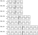
- FIGURES 3A to 3G illustrates sizes of yarns of a weft on a first level and a second level of an industrial textile in accordance with at least some embodiments.
- the yarns of the weft with a larger diameter alternate with the yarns of the weft with a smaller diameter in a pattern repeat.
- FIGURE 3A illustrates that every second yarn of the weft on the first level has a larger diameter than the other yarns of the weft on the first level.
- Every second yarn of the weft on the second level has a larger diameter than the other yarns of the weft on the second level.
- FIGURE 3B illustrates that every second yarn of the weft on the first level has a larger diameter than the other yarns of the wefts on the first level.
- Every second yarn of the weft on the second level has a larger diameter than the other yarn of the wefts on the second level.
- FIGURE 3C illustrates that every second yarn of the weft on the first level has a larger diameter than the other yarns of the weft on the first level.
- Every yarn of the weft on the second level has the same diameter, which diameter is smaller than the diameter of the larger yarn of the wefts on the first level.
- FIGURE 3D illustrates that every third yarn of the weft on the first level has a larger diameter than the other yarns of the weft on the first level.
- Every third yarn of the weft on the second level has a larger diameter than the other yarn of the wefts on the second level.
- FIGURE 3E illustrates that every third yarn of the weft on the first level has a larger diameter than the other yarns of the weft on the first level.
- Every third yarn of the weft on the second level has a larger diameter than the other yarn of the wefts on the second level.
- FIGURE 3F illustrates that every fourth yarn of the weft on the first level has a larger diameter than the other yarns of the weft on the first level.
- FIGURE 3G illustrates that every second yarn of the weft on the first level has a larger diameter than the other yarns of the weft on the first level.
- Every fourth yarn of the weft on the second level has a larger diameter than the other yarn of the wefts on the second level.
- the diameters of the yarns of the weft having larger diameter are 0.2 mm greater than the diameters of the yarns of the weft having smaller diameter.
- the diameters of the yarns of the weft differ from each other to form a textured textile surface.
- the diameters of the yarns of the weft having smaller diameter can be for example, under 0.6 mm, preferably 0.4-0.6 mm, more preferably 0.5 mm.
- the diameters of the yarns of the weft having larger diameter can be for example, over 0.6 mm, preferably 0.6-0.9 mm, more preferably 0.7 mm.
- FIGURE 4 illustrates a surface view of an industrial textile in accordance with at least some embodiments.
- the yarns 111, 112 of the first warp next to each other are arranged in such a manner that when a coincidentally selected warp yarn 111 is under the weft yarns, the warp yarn 112 next to the coincidentally selected warp 111 yarn is above the weft yarns.
- the yarns 121, 122 of the second warp next to each other are arranged in such a manner that when a coincidentally selected warp yarn 121 is under the weft yarn, the warp yarn 122 next to the coincidentally selected warp 121 yarn is above the weft yarn.
- FIGURE 5 illustrates a weaving pattern of an industrial textile in accordance with at least some embodiments.
- FW refers to a first warp of the industrial textile and SW refers to a second warp of the industrial textile.
- X denotes that the yarn of the first warp of the second warp is over a yarn of a weft.
- Numbers 1 to 8 refers to the warps 1 to 8.
- a coincidentally selected yarn of the first warp and the yarn of the second warp are arranged in such a manner that when the yarn of the first warp binds the yarns of the weft under two, the yarn of the second warp binds the yarns of the weft under two.
- a yarn of the first warp next to the coincidentally selected warp yarn of the first warp and a yarn of the second warp next to the coincidentally selected warp yarn are arranged in such manner that when the yarn of the first warp binds the yarns of the weft over two, the yarn of the second warp binds the yarns of the weft over one and under one.
- diameters of the yarns of the weft which the warp number 1 binds can be for example, 0.50 mm.
- Diameters of the yarns of the weft which the warp number 2 binds can be for example, 0.50 mm
- diameters of the yarns of the weft which the warp number 3 bind can be for example, 0.70 mm
- diameters of the yarns of the weft which the warp number 4 bind can be for example, 0.50 mm
- diameters of the yarns of the weft which the warp number 5 bind can be for example, 0.70 mm
- diameters of the yarns of the weft which the warp number 6 bind can be for example, 0.50 mm
- diameters of the yarns of the weft which the warp number 7 bind can be for example, 0.50 mm
- diameters of the yarns of the weft which the warp number 8 bind can be for example, 0.70 mm.
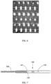
- FIGURE 6 illustrates a contact area of an industrial textile in accordance with at least some embodiments. There is higher peaks (white areas) and lower valleys in a thickness direction of the industrial textile.
- the contact area is under 20 %. This improves surface friction.
- a granular structure with the higher peaks and the lower valleys in the thickness direction of the industrial textile provides more friction and grip to carry paper mass or cake. Thanks to this structure, paper mass or cake can be also carried upwards. In addition, a time-consuming silicon stripe treatment can be avoided.
- the contact area is measured by a method comprising providing a sample of the industrial textile having a length of 130 mm in the machine direction and a width of 20 mm in the cross-machine direction, polishing the paper-side of the sample by removing 0.12 mm in a thickness direction of the sample, photographing the sample by a microscope camera, calibrating magnification by a calibration ruler, imaging the calibration ruler and the polished surface of the sample with the calibrated magnification, and measuring percentage of the contact area by an image processing software.
- An image area is 12 mm in the cross-machine direction.
- the first machine direction yarns 111, 112 of the first warp are flat yarns.
- the second machine direction yarns 121, 122 of the second warp are flat yarns.
- the cross-machine direction yarns 131, 132, 133, 134 of the weft are round yarns. However, also oval yarns can be used.
- FIGURE 7 illustrates a seam element 140 in accordance with at least some embodiments.
- the industrial textile 100 comprises a first edge 103 and a second edge 104, which the first edge 103 and the second edge 104 are configured to be connected together by the seam element 140.
- the seam element comprises a first part 141 connected to the first edge 103 and a second part 142 connected to the second edge 104.
- the granular surface of the industrial textile enables better grip of the seam element on the textile surface. Thus, strength of the seam is higher.
- FIGURE 7 illustrates that the first part 141 and the second part 142 of the seam element 140 have inner surfaces, which are arranged in the contact with the industrial textile 100.
- the inner surface of the first part 141 and the inner surface of the second part 142 of the seam element 140 are shaped to correspond to a surface texture of the industrial textile 100.
- the granular surface of the industrial textile with the shaped inner surface of the parts of the seam element enables better grip of the seam element on the textile surface.
- strength of the seam is higher, because the seam element do not slide out of its place during the use of the industrial textile.
- the inner surface of the first part 141 and the inner surface of the second part 142 of the seam element can comprise teeth configured to be attached to the industrial textile 100.
- the teeth can be configured to be attached to the lower valleys of the industrial textile.
- the first machine direction yarns 111, 112, the second machine direction yarns 121, 122 and the cross-machine direction yarns 131, 132, 133, 134 can consists essentially of a virgin or recycled polyethylene terephthalate (PET), polyphenylene sulfide (PPS), polyketone (PK), thermoplastic aliphatic polyketone (PK), polyether ether ketone (PEEK), polyamide (PA), polypropylene (PP), polyvinylidene difluoride (PVDF), polyolefin (PO), polyester (PES), polyphenylene sulfone (PPSU), polyurethane (PU), polyphenylene ether (PPE), polyphenylene ketone, polyphenylene etherketone (PEEK), liquid crystalline polymer, aliphatic polyketone, and/or biopolymer.
- PET polyethylene terephthalate
- PPS polyphenylene sulfide
- PK polyketone
- PK
- the industrial textile 100 is used as a conveyor fabric, a dryer fabric or a filter fabric.
Landscapes
- Engineering & Computer Science (AREA)
- Textile Engineering (AREA)
- Woven Fabrics (AREA)
Abstract
Description
- The present invention relates to industrial textiles, particularly industrial textiles used as conveyor fabrics, dryer fabrics or filter fabrics.
- A conveyor fabric can be used to transport paper mass, paper web or board web to a pulper or cake to a cellulose dryer. The conveyor fabric has a first surface and a second surface. The first surface is in contact with paper mass or cake, when the conveyor fabric is assembled to a conveyor. The second surface is in contact with a conveyor equipment when the conveyor fabric is assembled to the conveyor. The first side should have a coarse surface texture to provide high friction and grip for carrying paper mass or cake also upward. The second side should have a relative smooth surface to provide good wear resistance and performance. When extra grip is needed, the conveyor fabric can be equipped with silicon stripes. The silicon stripes are formed in a cross-machine direction of the conveyor fabric.
- However, the silicon stripe treatment is very time consuming. First, it bonds the labour force for hours for making silicon stripes. Secondly, drying of the silicon stripes takes several hours. In addition, when the fabric is drying, it takes up a lot of floor space for several hours.
-
EP3 601665 B1 discloses an industrial textile having a granular texture on the first surface. However, the industrial textile has substantially even surface topography with relatively small waviness. The industrial textile has relatively high contact surface area. Thus, material, such as dirt, on the first surface does not easily stick to the surface. - Therefore, there is need for improving industrial textiles, particularly developing alternatives to the silicone stripes.
- According to a first aspect of the present invention, there is provided an industrial textile having a machine direction and a cross-machine direction, and a first surface and a second surface, the industrial textile comprising a double warp comprising a first warp comprising first machine direction yarns, and a second warp comprising second machine direction yarns, the yarns of the first warp being arranged above the yarns of the second warp, a weft comprising cross-machine direction yarns, the yarns of the first warp and the yarns of the weft being bonded to each other according to a first predetermined pattern, the yarns of the second warp and the yarns of the weft being bonded to each other according to a second predetermined pattern, and the first predetermined pattern and the second predetermined pattern forming a textile structure, which comprises the yarns of the weft on a first level and the yarns of the weft on a second level in a thickness direction of the industrial textile, wherein yarns of the weft having smaller diameter are configured to alternate with yarns of the weft having larger diameter on the first level.
- According an embodiment, every second, third or fourth yarn of the weft on the first level has a larger diameter than the other yarns of the weft on the first level.
- According an embodiment, the yarns of the weft having smaller diameter are configured to alternate with the yarns of the weft having larger diameter on the second level.
- According an embodiment, the industrial textile has one yarn of the weft having larger diameter and one yarn of the weft having smaller diameter in a pattern repeat on the first level, and one yarn of the weft having larger diameter and one yarn of the weft having smaller diameter in a pattern repeat on the second level, one yarn of the weft having smaller diameter and one yarn of the weft having larger diameter in a pattern repeat on the second level, or every yarn of the weft on the second level has the same diameter, which diameter is smaller than the diameter of the larger yarns of the wefts on the first level.
- According to an embodiment, the industrial textile has one yarn of the weft having larger diameter and two yarns of the weft having smaller diameter in a pattern repeat on the first level, and one yarn of the weft having smaller diameter, one yarn of the weft having larger diameter and one yarn of the weft having smaller diameter in a pattern repeat on the second level, or one yarn of the weft having larger diameter and two yarn of the wefts having smaller diameter in a pattern repeat on the second level.
- According to an embodiment, the industrial textile has one yarn of the weft having larger diameter and three yarns of the weft having smaller diameter in a pattern repeat on the first level, and one yarn of the weft having smaller diameter, two yarns of the wefts having larger diameter and one yarn of the weft having smaller diameter in a pattern repeat on the second level.
- According to an embodiment, the industrial textile has one yarn of the weft having larger diameter and one yarn of the weft having smaller diameter in a pattern repeat on the first level, and one yarn of the weft having smaller diameter, one yarn of the weft having larger diameter and two yarns of the weft having smaller diameters in a pattern repeat on the second level.
- According to an embodiment, the diameters of the yarns of the weft having larger diameter are 0.2 mm greater than the diameters of the yarns of the weft having smaller diameter.
- According to an embodiment, in the first predetermined pattern, the yarns of the first warp are configured to bind the yarns of the weft under two and over two yarns of the weft.
- According to an embodiment, in the second predetermined patter, the yarns of the second warp are configured to bond the yarns of the weft under three yarns and over one yarn of the weft.
- According to an embodiment, the yarns of the first warp next to each other are arranged in such a manner that when a coincidentally selected warp yarn is under the weft yarns, the warp yarn next to the coincidentally selected warp yarn is above the weft yarn.
- According to an embodiment, the yarns of the second warp next to each other are arranged in such a manner that when a coincidentally selected warp yarn is under the weft yarn, the warp yarn next to the coincidentally selected warp yarn is above the weft yarn.
- According to an embodiment, a coincidentally selected yarn of the first warp and the yarn of the second warp are arranged in such a manner that when the yarn of the first warp binds the yarns of the weft under two, the yarn of the second warp binds the yarns of the weft under two, and a yarn of the first warp next to the coincidentally selected warp yarn of the first warp and a yarn of the second warp next to the coincidentally selected warp yarn are arranged in such manner that when the yarn of the first warp binds the yarns of the weft over two, the yarn of the second warp binds the yarns of the weft over one and under one.
- According to an embodiment, the industrial textile has a contact area under 20%.
- According to an embodiment, said contact area being measured by a method comprising providing a sample of the industrial textile having a length of 130 mm in machine direction and a width of 20 mm in cross-machine direction, polishing the paper-side of the sample by removing 0.12 mm in a thickness direction of the sample, photographing the sample by a microscope camera, calibrating magnification by a calibration ruler, imaging the calibration ruler and the polished surface of the sample with the calibrated magnification, and measuring the percentage of the contact area by an image processing software.
- According to an embodiment, the industrial textile comprises a first edge and a second edge, which the first edge and the second edge are configured to be connected together by a seam element, which comprises a first part connected to the first edge and a second part connected to the second edge.
- According to an embodiment, inner surfaces of the first part and inner surfaces of the second part of the seam element are shaped to correspond to a surface texture of the industrial textile.
- According to an embodiment, the inner surfaces of the first part and the inner surfaces of the second part of the seam element comprise teeth configured to be attached to the industrial textile.
- According to a second aspect of the present invention, there is provided use of an industrial textile as a conveyor fabric, a dryer fabric or a filter fabric.
-
-
FIGURE 1A illustrates a cross section of an industrial textile in a machine direction in accordance with at least some embodiments of the present invention; -
FIGURE 1B illustrates a cross section of yarns of a weft and a yarn of a first warp in a machine direction in accordance with at least some embodiments of the present invention; -
FIGURE 1C illustrates a cross section of yarns of a weft and a yarn of a second warp in a machine direction in accordance with at least some embodiments of the present invention; -
FIGURE 1D illustrates a cross section of yarns of a weft and a yarn of a first warp in a machine direction in accordance with at least some embodiments of the present invention; -
FIGURE 1E illustrates a cross section of yarns of a weft and a yarn of a second warp in a machine direction in accordance with at least some embodiments of the present invention; -
FIGURE 2A illustrates a cross section of an industrial textile in a machine direction in accordance with at least some embodiments of the present invention; -
FIGURE 2B illustrates a cross section of yarns of a weft and a yarn of a first warp in a machine direction in accordance with at least some embodiments of the present invention; -
FIGURE 2C illustrates a cross section of yarns of a weft and a yarn of a second warp in a machine direction in accordance with at least some embodiments of the present invention; -
FIGURE 2D illustrates a cross section of yarns of a weft and a yarn of a first warp in a machine direction in accordance with at least some embodiments of the present invention; -
FIGURE 2E illustrates a cross section of yarns of a weft and a yarn of a second warp in a machine direction in accordance with at least some embodiments of the present invention; -
FIGURE 3A illustrates that every second yarn of a weft on a first level has a larger diameter than other yarns of the weft on the first level in accordance with at least some embodiments of the present invention; -
FIGURE 3B illustrates that every second yarn of a weft on a first level has a larger diameter than other yarns of the weft on the first level in accordance with at least some embodiments of the present invention; -
FIGURE 3C illustrates that every second yarn of a weft on a first level has a larger diameter than other yarns of the weft on the first level in accordance with at least some embodiments of the present invention; -
FIGURE 3D illustrates that every third yarn of a weft on a first level has a larger diameter than other yarns of the weft on the first level in accordance with at least some embodiments of the present invention; -
FIGURE 3E illustrates that every third yarn of a weft on a first level has a larger diameter than other yarns of the weft on the first level in accordance with at least some embodiments of the present invention; -
FIGURE 3F illustrates that every fourth yarn of a weft on a first level has a larger diameter than other yarns of the weft on the first level in accordance with at least some embodiments of the present invention; -
FIGURE 3G illustrates that every second yarn of a weft on a first level has a larger diameter than other yarns of the weft on the first level in accordance with at least some embodiments of the present invention; -
FIGURE 4 illustrates a surface view of an industrial textile in accordance with at least some embodiments of the present invention; -
FIGURE 5 illustrates a weaving pattern of an industrial textile in accordance with at least some embodiments of the present invention; -
FIGURE 6 illustrates a contact area of an industrial textile in accordance with at least some embodiments of the present invention; and -
FIGURE 7 illustrates a seam element in accordance with at least some embodiments of the present invention. - In the present context, the term "first side" refers to a side of an industrial textile, which side is in contact with paper mass or cake, when the industrial fabric is assembled to a conveyor.
- In the present context, the term "second side" refers to a side of an industrial textile, which side is in contact with a conveyor equipment, when the industrial fabric is assembled to the conveyor.
- In the present context, the term "level" refers to a substantially horizontal plane with respect to a thickness direction of an industrial textile. The industrial textile has thickness in a dimension, which extends perpendicularly from the second side to the first side of the industrial textile. A first level of the industrial textile can be above a second level of the industrial textile in the thickness direction of the industrial textile, when the industrial fabric is assembled to the conveyor.
- In the present context, the term "machine direction" refers to a moving direction or a first direction of the industrial textile in the paper, board or tissue machine when the textile is assembled to the paper, board or tissue machine.
- In the present context, the term "cross-machine direction" refers to a direction, which is perpendicular to the moving direction or the first direction of the industrial textile in the paper, board or tissue machine when the textile is assembled to the paper, board or tissue machine.
- When extra grip is needed, the conveyor fabric can be equipped with silicon stripes. The silicon stripe treatment is very time consuming and binds labour force. At least some of the present embodiments solve the abovementioned problems.
- According to an embodiment, the
industrial textile 100 has a machine direction (MD) and a cross-machine direction (CMD), and afirst surface 101 and asecond surface 102. The industrial textile comprises a double warp comprising a first warp comprising firstmachine direction yarns machine direction yarns yarns yarns cross-machine direction yarns yarns yarns yarns yarns industrial textile 100. Yarns of the weft having smaller diameter are configured to alternate with yarns of the weft having larger diameter on the first level. This enables a coarse textured structure on the first side of the industrial textile. Higher peaks and lower valleys are formed in the industrial textile in a thickness direction of the industrial textile. The coarse structure provides more friction and grip to carry paper mass or cake. Thanks to coarse structure, paper mass or cake can be also carried upwards. In addition, a time-consuming silicon stripe treatment can be avoided. - The
industrial textile 100 comprises afirst edge 103 and asecond edge 104. Thefirst edge 103 and thesecond edge 104 can be connected together to form a loop. - According to an embodiment, in the first predetermined pattern, the
yarns yarns yarns - According to an embodiment, in the second predetermined patter, the
yarns yarns yarns yarn 133 of the weft. -
FIGURE 1A illustrates a cross section of anindustrial textile 100 in a machine direction in accordance with at least some embodiments. Theindustrial textile 100 comprises theyarns yarns yarns yarns yarns yarn 111 of the first warp and theyarn 121 of the second warp are configured to form a first row of theindustrial textile 100, and theyarn 112 of the first warp and theyarn 122 of the second warp are configured to form a second row of theindustrial textile 100. -
FIGURE 1B illustrates a cross section of theyarns yarn 112 of the first warp in a machine direction in accordance with at least some embodiments. Theyarn 112 of the first warp forming the second row of theindustrial textile 100 is configured to bind theyarns yarns -
FIGURE 1C illustrates a cross section of theyarns yarn 122 of the second warp in a machine direction in accordance with at least some embodiments. Theyarn 122 of the second warp forming the second row of theindustrial textile 100 is configured to bind theyarns yarn 134 of the weft. -
FIGURE 1D illustrates a cross section of yarns of a weft and a yarn of a first warp in a machine direction in accordance with at least some embodiments. Theyarn 111 of the first warp forming the first row of theindustrial textile 100 is configured to bind theyarns yarns -
FIGURE 1E illustrates a cross section of yarns of a weft and a yarn of a second warp in a machine direction in accordance with at least some embodiments. Theyarn 121 of the second warp forming the first row of theindustrial textile 100 is configured to bind theyarns -
FIGURE 2A illustrates a cross section of an industrial textile in a machine direction. Theindustrial textile 100 comprises theyarns yarns yarns yarns yarns yarn 111 of the first warp and theyarn 121 of the second warp are configured to form a first row of theindustrial textile 100, and theyarn 112 of the first warp and theyarn 122 of the second warp are configured to form a second row of theindustrial textile 100. -
FIGURE 2B illustrates a cross section of theyarns yarn 112 of a first warp in a machine direction in accordance with at least some embodiments. Theyarn 112 of the first warp forming the second row of theindustrial textile 100 is configured to bind theyarns yarns -
FIGURE 2C illustrates a cross section of theyarns yarn 122 of the second warp in a machine direction in accordance with at least some embodiments. Theyarn 122 of the second warp forming the second row of theindustrial textile 100 is configured to bind theyarns yarns -
FIGURE 2D illustrates a cross section of the yarns of theweft yarn 111 of the first warp forming the first row of theindustrial textile 100 is configured to bind theyarns yarns -
FIGURE 2E illustrates a cross section of the yarns of theweft yarn 121 of the second warp in a machine direction in accordance with at least some embodiments. Theyarn 121 of the second warp forming the first row of theindustrial textile 100 is configured to bind theyarns - The industrial textile can comprise the yarns of the weft having two to four different diameters. Preferably, there are the yarns of the weft having two different diameters.
- According to an embodiment, every second, third or fourth yarn of the weft on the first level L1 has a larger diameter than the other yarns of the weft on the first level L1. This enables a coarse structure on the first side of the industrial textile.
- According to an embodiment, the yarns of the weft having smaller diameter are configured to alternate with the yarns of the weft having larger diameter on the second level L2.
- According to an embodiment, the
industrial textile 100 has one yarn of the weft having larger diameter and one yarn of the weft having smaller diameter in a pattern repeat on the first level. In addition, theindustrial textile 100 has one yarn of the weft having larger diameter and one yarn of the weft having smaller diameter in a pattern repeat on the second level, one yarn of the weft having smaller diameter and one yarn of the weft having larger diameter in a pattern repeat on the second level, or every yarn of the weft on the second level has the same diameter, which diameter is smaller than the diameter of the larger yarns of the wefts on the first level. This enables a coarse structure on the first side and a relative smooth structure on the second side of the industrial textile. - According to an embodiment, the
industrial textile 100 has one yarn of the weft having larger diameter and two yarns of the weft having smaller diameter in a pattern repeat on the first level. In addition, the industrial textile has one yarn of the weft having smaller diameter, one yarn of the weft having larger diameter and one yarn of the weft having smaller diameter in a pattern repeat on the second level, or one yarn of the weft having larger diameter and two yarn of the wefts having smaller diameter in a pattern repeat on the second level. This enables a coarse structure on the first side and a relative smooth structure on the second side of the industrial textile. - According to an embodiment, the
industrial textile 100 has one yarn of the weft having larger diameter and three yarns of the weft having smaller diameter in a pattern repeat on the first level. In addition, the industrial textile has one yarn of the weft having smaller diameter, two yarns of the wefts having larger diameter and one yarn of the weft having smaller diameter in a pattern repeat on the second level. This enables a coarse structure on the first side and a relative smooth structure on the second side of the industrial textile. - According to an embodiment, the
industrial textile 100 has one yarn of the weft having larger diameter and one yarn of the weft having smaller diameter in a pattern repeat on the first level. In addition, the industrial textile has one yarn of the weft having smaller diameter, one yarn of the weft having larger diameter and two yarns of the weft having smaller diameters in a pattern repeat on the second level. This enables a coarse structure on the first side and a relative smooth structure on the second side of the industrial textile. -
FIGURES 3A to 3G illustrates sizes of yarns of a weft on a first level and a second level of an industrial textile in accordance with at least some embodiments. The yarns of the weft with a larger diameter alternate with the yarns of the weft with a smaller diameter in a pattern repeat. -
FIGURE 3A illustrates that every second yarn of the weft on the first level has a larger diameter than the other yarns of the weft on the first level. Thus, there is one yarn of the weft having larger diameter and one yarn of the weft having smaller diameter in a pattern repeat on the first level. Every second yarn of the weft on the second level has a larger diameter than the other yarns of the weft on the second level. Thus, there is one yarn of the weft having larger diameter and one yarn of the weft having smaller diameter in a pattern repeat on the second level. -
FIGURE 3B illustrates that every second yarn of the weft on the first level has a larger diameter than the other yarns of the wefts on the first level. Thus, there is one yarn of the weft having larger diameter and one yarn of the weft having smaller diameter in a pattern repeat on the first level. Every second yarn of the weft on the second level has a larger diameter than the other yarn of the wefts on the second level. Thus, there is one yarn of the weft having smaller diameter and one yarn of the weft having larger diameter in a pattern repeat on the second level. -
FIGURE 3C illustrates that every second yarn of the weft on the first level has a larger diameter than the other yarns of the weft on the first level. Thus, there is one yarn of the weft having larger diameter and one yarn of the weft having smaller diameter in a pattern repeat on the first level. Every yarn of the weft on the second level has the same diameter, which diameter is smaller than the diameter of the larger yarn of the wefts on the first level. -
FIGURE 3D illustrates that every third yarn of the weft on the first level has a larger diameter than the other yarns of the weft on the first level. Thus, there is one yarn of the weft having larger diameter and two yarn of the wefts having smaller diameter in a pattern repeat on the first level. Every third yarn of the weft on the second level has a larger diameter than the other yarn of the wefts on the second level. Thus, there is one yarn of the weft having smaller diameter, one yarn of the weft having larger diameter and one yarn of the weft having smaller diameter in a pattern repeat on the second level. -
FIGURE 3E illustrates that every third yarn of the weft on the first level has a larger diameter than the other yarns of the weft on the first level. Thus, there is one yarn of the weft having larger diameter and two yarn of the wefts having smaller diameter in a pattern repeat on the first level. Every third yarn of the weft on the second level has a larger diameter than the other yarn of the wefts on the second level. Thus, there is one yarn of the weft having larger diameter and two yarn of the wefts having smaller diameter in a pattern repeat on the second level. -
FIGURE 3F illustrates that every fourth yarn of the weft on the first level has a larger diameter than the other yarns of the weft on the first level. Thus, there is one yarn of the weft having larger diameter and three yarns of the weft having smaller diameter in a pattern repeat on the first level. There is one yarn of the weft having smaller diameter, two yarns of the wefts having larger diameter and one yarn of the weft having smaller diameter in a pattern repeat on the second level. -
FIGURE 3G illustrates that every second yarn of the weft on the first level has a larger diameter than the other yarns of the weft on the first level. Thus, there is one yarn of the weft having larger diameter and one yarn of the weft having smaller diameter in a pattern repeat on the first level. Every fourth yarn of the weft on the second level has a larger diameter than the other yarn of the wefts on the second level. Thus, there is one yarn of the weft having smaller diameter, one yarn of the weft having larger diameter and two yarns of the weft having smaller diameters in a pattern repeat on the second level. - The diameters of the yarns of the weft having larger diameter are 0.2 mm greater than the diameters of the yarns of the weft having smaller diameter. Thus, the diameters of the yarns of the weft differ from each other to form a textured textile surface.
- The diameters of the yarns of the weft having smaller diameter can be for example, under 0.6 mm, preferably 0.4-0.6 mm, more preferably 0.5 mm.
- The diameters of the yarns of the weft having larger diameter can be for example, over 0.6 mm, preferably 0.6-0.9 mm, more preferably 0.7 mm.
-
FIGURE 4 illustrates a surface view of an industrial textile in accordance with at least some embodiments. Theyarns warp yarn 111 is under the weft yarns, thewarp yarn 112 next to the coincidentally selectedwarp 111 yarn is above the weft yarns. Furthermore, theyarns warp yarn 121 is under the weft yarn, thewarp yarn 122 next to the coincidentally selectedwarp 121 yarn is above the weft yarn. -
FIGURE 5 illustrates a weaving pattern of an industrial textile in accordance with at least some embodiments. FW refers to a first warp of the industrial textile and SW refers to a second warp of the industrial textile. X denotes that the yarn of the first warp of the second warp is over a yarn of a weft.Numbers 1 to 8 refers to thewarps 1 to 8. A coincidentally selected yarn of the first warp and the yarn of the second warp are arranged in such a manner that when the yarn of the first warp binds the yarns of the weft under two, the yarn of the second warp binds the yarns of the weft under two. In addition, a yarn of the first warp next to the coincidentally selected warp yarn of the first warp and a yarn of the second warp next to the coincidentally selected warp yarn are arranged in such manner that when the yarn of the first warp binds the yarns of the weft over two, the yarn of the second warp binds the yarns of the weft over one and under one. - Referring to
FIGURE 5 , diameters of the yarns of the weft which thewarp number 1 binds can be for example, 0.50 mm. Diameters of the yarns of the weft which thewarp number 2 binds can be for example, 0.50 mm, diameters of the yarns of the weft which thewarp number 3 bind can be for example, 0.70 mm, diameters of the yarns of the weft which thewarp number 4 bind can be for example, 0.50 mm, diameters of the yarns of the weft which thewarp number 5 bind can be for example, 0.70 mm, diameters of the yarns of the weft which thewarp number 6 bind can be for example, 0.50 mm, diameters of the yarns of the weft which thewarp number 7 bind can be for example, 0.50 mm, and diameters of the yarns of the weft which thewarp number 8 bind can be for example, 0.70 mm. This enables a coarse textured structure on the first side of the industrial textile. -
FIGURE 6 illustrates a contact area of an industrial textile in accordance with at least some embodiments. There is higher peaks (white areas) and lower valleys in a thickness direction of the industrial textile. - The contact area is under 20 %. This improves surface friction. A granular structure with the higher peaks and the lower valleys in the thickness direction of the industrial textile provides more friction and grip to carry paper mass or cake. Thanks to this structure, paper mass or cake can be also carried upwards. In addition, a time-consuming silicon stripe treatment can be avoided.
- The contact area is measured by a method comprising providing a sample of the industrial textile having a length of 130 mm in the machine direction and a width of 20 mm in the cross-machine direction, polishing the paper-side of the sample by removing 0.12 mm in a thickness direction of the sample, photographing the sample by a microscope camera, calibrating magnification by a calibration ruler, imaging the calibration ruler and the polished surface of the sample with the calibrated magnification, and measuring percentage of the contact area by an image processing software. An image area is 12 mm in the cross-machine direction.
- According to an embodiment, the first
machine direction yarns - According to an embodiment, the second
machine direction yarns - According to an embodiment, the
cross-machine direction yarns -
FIGURE 7 illustrates aseam element 140 in accordance with at least some embodiments. Theindustrial textile 100 comprises afirst edge 103 and asecond edge 104, which thefirst edge 103 and thesecond edge 104 are configured to be connected together by theseam element 140. The seam element comprises afirst part 141 connected to thefirst edge 103 and asecond part 142 connected to thesecond edge 104. The granular surface of the industrial textile enables better grip of the seam element on the textile surface. Thus, strength of the seam is higher. -
FIGURE 7 illustrates that thefirst part 141 and thesecond part 142 of theseam element 140 have inner surfaces, which are arranged in the contact with theindustrial textile 100. The inner surface of thefirst part 141 and the inner surface of thesecond part 142 of theseam element 140 are shaped to correspond to a surface texture of theindustrial textile 100. The granular surface of the industrial textile with the shaped inner surface of the parts of the seam element enables better grip of the seam element on the textile surface. Thus, strength of the seam is higher, because the seam element do not slide out of its place during the use of the industrial textile. - Alternatively, the inner surface of the
first part 141 and the inner surface of thesecond part 142 of the seam element can comprise teeth configured to be attached to theindustrial textile 100. The teeth can be configured to be attached to the lower valleys of the industrial textile. - According to an embodiment, the first
machine direction yarns machine direction yarns cross-machine direction yarns - According to an embodiment, the
industrial textile 100 is used as a conveyor fabric, a dryer fabric or a filter fabric. - It is to be understood that the embodiments of the invention disclosed are not limited to the particular structures, process steps, or materials disclosed herein, but are extended to equivalents thereof as would be recognized by those ordinarily skilled in the relevant arts. It should also be understood that terminology employed herein is used for the purpose of describing particular embodiments only and is not intended to be limiting.
- Reference throughout this specification to "an embodiment" means that a particular feature, structure, or characteristic described in connection with the embodiment is included in at least one embodiment of the present invention. Thus, appearances of the phrase "in an embodiment" in various places throughout this specification are not necessarily all referring to the same embodiment.
- As used herein, a plurality of items, structural elements, compositional elements, and/or materials may be presented in a common list for convenience. However, these lists should be construed as though each member of the list is individually identified as a separate and unique member. Thus, no individual member of such list should be construed as a de facto equivalent of any other member of the same list solely based on their presentation in a common group without indications to the contrary. In addition, various embodiments and example of the present invention may be referred to herein along with alternatives for the various components thereof. It is understood that such embodiments, examples, and alternatives are not to be construed as de facto equivalents of one another, but are to be considered as separate and autonomous representations of the present invention.
- Furthermore, the described features, structures, or characteristics may be combined in any suitable manner in one or more embodiments. In the following description, numerous specific details are provided, such as examples of lengths, widths, shapes, etc., to provide a thorough understanding of embodiments of the invention. One skilled in the relevant art will recognize, however, that the invention can be practiced without one or more of the specific details, or with other methods, components, materials, etc. In other instances, well-known structures, materials, or operations are not shown or described in detail to avoid obscuring aspects of the invention.
- While the forgoing examples are illustrative of the principles of the present invention in one or more particular applications, it will be apparent to those of ordinary skill in the art that numerous modifications in form, usage and details of implementation can be made without the exercise of inventive faculty, and without departing from the principles and concepts of the invention. Accordingly, it is not intended that the invention be limited, except as by the claims set forth below.
- The verb "to comprise" is used in this document as open limitations that neither exclude nor require the existence of also un-recited features. The features recited in depending claims are mutually freely combinable unless otherwise explicitly stated. Furthermore, it is to be understood that the use of "a" or "an", i.e. a singular form, throughout this document does not exclude a plurality.
-
- 100
- industrial textile
- 101
- first surface
- 102
- second surface
- 103
- first edge
- 104
- second edge
- 111, 112
- yarn of first warp
- 121, 122
- yarn of second warp
- 131, 132, 133, 134
- yarn of the weft
- 140
- seam element
- 141
- first part of seam element
- 142
- second part of seam element
- L1
- first level
- L2
- second level
Claims (17)
- An industrial textile (100) having a machine direction (MD) and a cross-machine direction (CMD), and a first surface (101) and a second surface (102), the industrial textile comprising:- a double warp, comprising:∘ a first warp comprising first machine direction yarns (111, 112), and∘ a second warp comprising second machine direction yarns (121, 122),the yarns (111, 112) of the first warp being arranged above the yarns (121, 122) of the second warp,- a weft comprising cross-machine direction yarns (131, 132, 133, 134),- the yarns (111, 112) of the first warp and the yarns (131, 132, 133, 134) of the weft being bonded to each other according to a first predetermined pattern,- the yarns (121, 122) of the second warp and the yarns (131, 132, 133, 134) of the weft being bonded to each other according to a second predetermined pattern, and- the first predetermined pattern and the second predetermined pattern forming a textile structure, which comprises the yarns of the weft on a first level (L1) and the yarns of the weft on a second level (L2) in a thickness direction of the industrial textile (100),wherein yarns of the weft having smaller diameter are configured to alternate with yarns of the weft having larger diameter on the first level (LI),
characterized in that the industrial textile (100) has a contact area under 20 %. - The industrial textile (100) of claim 1, wherein every second, third or fourth yarn of the weft on the first level (L1) has a larger diameter than the other yarns of the weft on the first level (L1).
- The industrial textile (100) of any one of the preceding claims, wherein the yarns of the weft having smaller diameter are configured to alternate with the yarns of the weft having larger diameter on the second level (L2).
- The industrial textile (100) of claim 3, which industrial textile (100) has one yarn of the weft having larger diameter and one yarn of the weft having smaller diameter in a pattern repeat on the first level (LI), and- one yarn of the weft having larger diameter and one yarn of the weft having smaller diameter in a pattern repeat on the second level (L2), or- one yarn of the weft having smaller diameter and one yarn of the weft having larger diameter in a pattern repeat on the second level (L2).
- The industrial textile (100) of claim 3, which industrial textile (100) has one yarn of the weft having larger diameter and two yarns of the weft having smaller diameter in a pattern repeat on the first level (LI), and- one yarn of the weft having smaller diameter, one yarn of the weft having larger diameter and one yarn of the weft having smaller diameter in a pattern repeat on the second level (L2), or- one yarn of the weft having larger diameter and two yarn of the wefts having smaller diameter in a pattern repeat on the second level (L2).
- The industrial textile (100) of claim 3, which industrial textile (100) has one yarn of the weft having larger diameter and three yarns of the weft having smaller diameter in a pattern repeat on the first level (LI), and
one yarn of the weft having smaller diameter, two yarns of the wefts having larger diameter and one yarn of the weft having smaller diameter in a pattern repeat on the second level (L2). - The industrial textile (100) of claim 3, which industrial textile (100) has one yarn of the weft having larger diameter and one yarn of the weft having smaller diameter in a pattern repeat on the first level (L1), and
one yarn of the weft having smaller diameter, one yarn of the weft having larger diameter and two yarns of the weft having smaller diameters in a pattern repeat on the second level (L2). - The industrial textile (100) of any one of the preceding claims, wherein the diameters of the yarns of the weft having larger diameter are 0.2 mm greater than the diameters of the yarns of the weft having smaller diameter.
- The industrial textile (100) of any one of the preceding claims, wherein in the first predetermined pattern, the yarns (111, 112) of the first warp are configured to bind the yarns (131, 132, 133, 134) of the weft under two (131, 132) and over two yarns (133, 134) of the weft.
- The industrial textile (100) of any one of the preceding claims, wherein in the second predetermined patter, the yarns (121, 122) of the second warp are configured to bond the yarns (131, 132, 133, 134) of the weft under three yarns (131, 132, 133) and over one yarn (134) of the weft.
- The industrial textile (100) of any one of the preceding claims, wherein the yarns (111, 112) of the first warp next to each other are arranged in such a manner that when a coincidentally selected warp yarn (111) is under the weft yarns, the warp yarn (112) next to the coincidentally selected warp (111) yarn is above the weft yarns.
- The industrial textile (100) of any one of the preceding claims, wherein the yarns (121, 122) of the second warp next to each other are arranged in such a manner that when a coincidentally selected warp yarn (121) is under the weft yarn, the warp yarn (122) next to the coincidentally selected warp (121) yarn is above the weft yarn.
- The industrial textile (100) of any one of the preceding claims, wherein:- a coincidentally selected yarn (111) of the first warp and the yarn (121) of the second warp are arranged in such a manner that when the yarn (111) of the first warp binds the yarns (131, 132) of the weft under two, the yarn (121) of the second warp binds the yarns (131, 132) of the weft under two, and- a yarn (112) of the first warp next to the coincidentally selected warp yarn (111) of the first warp and a yarn (122) of the second warp next to the coincidentally selected warp yarn (121) are arranged in such manner that when the yarn (112) of the first warp binds the yarns (131, 132) of the weft over two, the yarn (122) of the second warp binds the yarns (131, 132) of the weft over one and under one.
- The industrial textile (100) of any one of the preceding claims, which industrial textile (100) comprises a first edge (103) and a second edge (104), which the first edge (103) and the second edge (104) are configured to be connected together by a seam element (140), which comprises a first part (141) connected to the first edge (103) and a second part (142) connected to the second edge (104).
- The industrial textile (100) of claim 14, wherein an inner surface of the first part (141) and an inner surface of the second part (142) of the seam element (140) are shaped to correspond to a surface texture of the industrial textile (100).
- The industrial textile (100) of claim 14, wherein the inner surface of the first part (141) and the inner surface of the second part (142) of the seam element (140) comprise teeth configured to be attached to the industrial textile (100).
- Use of an industrial textile of any one of the preceding claims as a conveyor fabric, a dryer fabric or a filter fabric.
Applications Claiming Priority (1)
| Application Number | Priority Date | Filing Date | Title |
|---|---|---|---|
| FI20216031A FI131402B1 (en) | 2021-10-06 | 2021-10-06 | Industrial textile |
Publications (2)
| Publication Number | Publication Date |
|---|---|
| EP4163435A2 true EP4163435A2 (en) | 2023-04-12 |
| EP4163435A3 EP4163435A3 (en) | 2023-05-10 |
Family
ID=83594239
Family Applications (1)
| Application Number | Title | Priority Date | Filing Date |
|---|---|---|---|
| EP22199531.9A Pending EP4163435A3 (en) | 2021-10-06 | 2022-10-04 | Industrial textile |
Country Status (4)
| Country | Link |
|---|---|
| US (1) | US11965272B2 (en) |
| EP (1) | EP4163435A3 (en) |
| CN (1) | CN115928287B (en) |
| FI (1) | FI131402B1 (en) |
Citations (1)
| Publication number | Priority date | Publication date | Assignee | Title |
|---|---|---|---|---|
| EP3601665A1 (en) | 2017-03-24 | 2020-02-05 | Valmet Technologies Oy | An industrial textile |
Family Cites Families (17)
| Publication number | Priority date | Publication date | Assignee | Title |
|---|---|---|---|---|
| US3207659A (en) * | 1963-01-22 | 1965-09-21 | Huyck Corp | Method of making papermaker's fabric and the finished fabric |
| JPS63145496A (en) * | 1986-12-02 | 1988-06-17 | 日本フイルコン株式会社 | Papermaking multilayer fabric |
| EP0608342B1 (en) * | 1991-10-11 | 1995-12-13 | Asten, Inc. | Woven papermakers fabric having a unibody seam and a method for making the same |
| US5169709A (en) * | 1991-10-16 | 1992-12-08 | Wangner Systems Corporation | Paper machine forming fabric with controlled porosity |
| US5422166A (en) * | 1993-02-12 | 1995-06-06 | Wangner Systems Corporation | Abrasion resisting edge for a forming fabric |
| US5795835A (en) * | 1995-08-28 | 1998-08-18 | The Tensar Corporation | Bonded composite knitted structural textiles |
| US5769131A (en) * | 1997-05-16 | 1998-06-23 | Albany International Corp. | Seam design for a dryer fabric |
| JP3844272B2 (en) * | 1997-10-03 | 2006-11-08 | 株式会社小林製作所 | Papermaking belt for building material production and transfer belt for building material production |
| MX2010005969A (en) * | 2007-11-30 | 2010-09-30 | Nippon Filcon Kk | Industrial fabric for paper making and press. |
| JP5280160B2 (en) * | 2008-11-12 | 2013-09-04 | 日本フイルコン株式会社 | Industrial multilayer fabric with drawn wefts |
| US8961742B2 (en) * | 2011-07-22 | 2015-02-24 | Astenjohnson, Inc. | Multiaxial press felt base fabric including cabled monofilaments |
| US10858766B2 (en) * | 2013-07-31 | 2020-12-08 | Nippon Filcon Co., Ltd. | Industrial fabric |
| DE102013215779A1 (en) * | 2013-08-09 | 2015-02-12 | Voith Patent Gmbh | Covering with seam connection |
| FI20155205L (en) * | 2015-03-24 | 2016-09-25 | Valmet Technologies Oy | Drying wire |
| DE102016107811A1 (en) * | 2016-04-27 | 2017-11-02 | AstenJohnson PGmbH | Industrial fabric, in particular conveyor belt |
| EP3631064B1 (en) * | 2017-05-30 | 2022-03-30 | AstenJohnson, Inc. | High stability stacked warp yarn dryer fabric with long warp floats |
| FR3087452B1 (en) * | 2018-10-18 | 2020-10-30 | Ferrari Serge Sas | TEXTILE COMBINING SOFTNESS, ABRASION RESISTANCE AND EXTERIOR USE |
-
2021
- 2021-10-06 FI FI20216031A patent/FI131402B1/en active
-
2022
- 2022-09-30 CN CN202211209994.9A patent/CN115928287B/en active Active
- 2022-10-03 US US17/959,094 patent/US11965272B2/en active Active
- 2022-10-04 EP EP22199531.9A patent/EP4163435A3/en active Pending
Patent Citations (1)
| Publication number | Priority date | Publication date | Assignee | Title |
|---|---|---|---|---|
| EP3601665A1 (en) | 2017-03-24 | 2020-02-05 | Valmet Technologies Oy | An industrial textile |
Also Published As
| Publication number | Publication date |
|---|---|
| EP4163435A3 (en) | 2023-05-10 |
| US11965272B2 (en) | 2024-04-23 |
| US20230105047A1 (en) | 2023-04-06 |
| CN115928287B (en) | 2025-04-15 |
| CN115928287A (en) | 2023-04-07 |
| FI20216031A1 (en) | 2023-04-07 |
| FI131402B1 (en) | 2025-04-02 |
Similar Documents
| Publication | Publication Date | Title |
|---|---|---|
| EP1630271B1 (en) | Industrial Two-layer fabric | |
| US7896034B2 (en) | Heat- and corrosion-resistant fabric | |
| EP3904574B1 (en) | Multilayer weave for nonwoven fabric | |
| US12312716B2 (en) | Industrial fabric | |
| US7426943B2 (en) | Industrial two-layer fabric | |
| RU2243305C2 (en) | Drying sieve | |
| US20180135247A1 (en) | Seamless press felt with intermediate elastic carrier layer | |
| EP3779036B1 (en) | Industrial two-layer fabric | |
| JP5711946B2 (en) | Industrial two-layer fabric | |
| EP4163435A2 (en) | Industrial textile | |
| US20250283256A1 (en) | Industrial fabric | |
| US9834870B2 (en) | Industrial two-layer fabric | |
| US9359699B2 (en) | Industrial two-layer fabric | |
| JP6509692B2 (en) | Papermaking fabrics | |
| US20250389063A1 (en) | Industrial fabric | |
| EP3140226A1 (en) | Industrial textile |
Legal Events
| Date | Code | Title | Description |
|---|---|---|---|
| PUAI | Public reference made under article 153(3) epc to a published international application that has entered the european phase |
Free format text: ORIGINAL CODE: 0009012 |
|
| STAA | Information on the status of an ep patent application or granted ep patent |
Free format text: STATUS: THE APPLICATION HAS BEEN PUBLISHED |
|
| PUAL | Search report despatched |
Free format text: ORIGINAL CODE: 0009013 |
|
| AK | Designated contracting states |
Kind code of ref document: A2 Designated state(s): AL AT BE BG CH CY CZ DE DK EE ES FI FR GB GR HR HU IE IS IT LI LT LU LV MC ME MK MT NL NO PL PT RO RS SE SI SK SM TR |
|
| AK | Designated contracting states |
Kind code of ref document: A3 Designated state(s): AL AT BE BG CH CY CZ DE DK EE ES FI FR GB GR HR HU IE IS IT LI LT LU LV MC ME MK MT NL NO PL PT RO RS SE SI SK SM TR |
|
| RIC1 | Information provided on ipc code assigned before grant |
Ipc: D21F 1/00 20060101AFI20230403BHEP |
|
| P01 | Opt-out of the competence of the unified patent court (upc) registered |
Effective date: 20230602 |
|
| STAA | Information on the status of an ep patent application or granted ep patent |
Free format text: STATUS: REQUEST FOR EXAMINATION WAS MADE |
|
| 17P | Request for examination filed |
Effective date: 20231109 |
|
| RBV | Designated contracting states (corrected) |
Designated state(s): AL AT BE BG CH CY CZ DE DK EE ES FI FR GB GR HR HU IE IS IT LI LT LU LV MC ME MK MT NL NO PL PT RO RS SE SI SK SM TR |