EP4163242A1 - An electronic device for locating a functional disorder at a spinning and winding section of a spinning mill and a method for locating the same - Google Patents
An electronic device for locating a functional disorder at a spinning and winding section of a spinning mill and a method for locating the same Download PDFInfo
- Publication number
- EP4163242A1 EP4163242A1 EP21201596.0A EP21201596A EP4163242A1 EP 4163242 A1 EP4163242 A1 EP 4163242A1 EP 21201596 A EP21201596 A EP 21201596A EP 4163242 A1 EP4163242 A1 EP 4163242A1
- Authority
- EP
- European Patent Office
- Prior art keywords
- spinning
- winding
- yarn
- parameters
- machines
- Prior art date
- Legal status (The legal status is an assumption and is not a legal conclusion. Google has not performed a legal analysis and makes no representation as to the accuracy of the status listed.)
- Withdrawn
Links
Images


Classifications
-
- D—TEXTILES; PAPER
- D01—NATURAL OR MAN-MADE THREADS OR FIBRES; SPINNING
- D01H—SPINNING OR TWISTING
- D01H13/00—Other common constructional features, details or accessories
- D01H13/32—Counting, measuring, recording or registering devices
-
- B—PERFORMING OPERATIONS; TRANSPORTING
- B65—CONVEYING; PACKING; STORING; HANDLING THIN OR FILAMENTARY MATERIAL
- B65H—HANDLING THIN OR FILAMENTARY MATERIAL, e.g. SHEETS, WEBS, CABLES
- B65H67/00—Replacing or removing cores, receptacles, or completed packages at paying-out, winding, or depositing stations
- B65H67/06—Supplying cores, receptacles, or packages to, or transporting from, winding or depositing stations
- B65H67/063—Marking or identifying devices for packages
-
- D—TEXTILES; PAPER
- D01—NATURAL OR MAN-MADE THREADS OR FIBRES; SPINNING
- D01H—SPINNING OR TWISTING
- D01H13/00—Other common constructional features, details or accessories
- D01H13/14—Warning or safety devices, e.g. automatic fault detectors, stop motions ; Monitoring the entanglement of slivers in drafting arrangements
-
- G—PHYSICS
- G05—CONTROLLING; REGULATING
- G05B—CONTROL OR REGULATING SYSTEMS IN GENERAL; FUNCTIONAL ELEMENTS OF SUCH SYSTEMS; MONITORING OR TESTING ARRANGEMENTS FOR SUCH SYSTEMS OR ELEMENTS
- G05B13/00—Adaptive control systems, i.e. systems automatically adjusting themselves to have a performance which is optimum according to some preassigned criterion
- G05B13/02—Adaptive control systems, i.e. systems automatically adjusting themselves to have a performance which is optimum according to some preassigned criterion electric
- G05B13/0265—Adaptive control systems, i.e. systems automatically adjusting themselves to have a performance which is optimum according to some preassigned criterion electric the criterion being a learning criterion
- G05B13/0285—Adaptive control systems, i.e. systems automatically adjusting themselves to have a performance which is optimum according to some preassigned criterion electric the criterion being a learning criterion using neural networks and fuzzy logic
-
- B—PERFORMING OPERATIONS; TRANSPORTING
- B65—CONVEYING; PACKING; STORING; HANDLING THIN OR FILAMENTARY MATERIAL
- B65H—HANDLING THIN OR FILAMENTARY MATERIAL, e.g. SHEETS, WEBS, CABLES
- B65H2701/00—Handled material; Storage means
- B65H2701/30—Handled filamentary material
- B65H2701/31—Textiles threads or artificial strands of filaments
-
- B—PERFORMING OPERATIONS; TRANSPORTING
- B65—CONVEYING; PACKING; STORING; HANDLING THIN OR FILAMENTARY MATERIAL
- B65H—HANDLING THIN OR FILAMENTARY MATERIAL, e.g. SHEETS, WEBS, CABLES
- B65H63/00—Warning or safety devices, e.g. automatic fault detectors, stop-motions ; Quality control of the package
-
- B—PERFORMING OPERATIONS; TRANSPORTING
- B65—CONVEYING; PACKING; STORING; HANDLING THIN OR FILAMENTARY MATERIAL
- B65H—HANDLING THIN OR FILAMENTARY MATERIAL, e.g. SHEETS, WEBS, CABLES
- B65H63/00—Warning or safety devices, e.g. automatic fault detectors, stop-motions ; Quality control of the package
- B65H63/006—Warning or safety devices, e.g. automatic fault detectors, stop-motions ; Quality control of the package quality control of the package
-
- B—PERFORMING OPERATIONS; TRANSPORTING
- B65—CONVEYING; PACKING; STORING; HANDLING THIN OR FILAMENTARY MATERIAL
- B65H—HANDLING THIN OR FILAMENTARY MATERIAL, e.g. SHEETS, WEBS, CABLES
- B65H63/00—Warning or safety devices, e.g. automatic fault detectors, stop-motions ; Quality control of the package
- B65H63/02—Warning or safety devices, e.g. automatic fault detectors, stop-motions ; Quality control of the package responsive to reduction in material tension, failure of supply, or breakage, of material
-
- D—TEXTILES; PAPER
- D01—NATURAL OR MAN-MADE THREADS OR FIBRES; SPINNING
- D01H—SPINNING OR TWISTING
- D01H13/00—Other common constructional features, details or accessories
- D01H13/14—Warning or safety devices, e.g. automatic fault detectors, stop motions ; Monitoring the entanglement of slivers in drafting arrangements
- D01H13/16—Warning or safety devices, e.g. automatic fault detectors, stop motions ; Monitoring the entanglement of slivers in drafting arrangements responsive to reduction in material tension, failure of supply, or breakage, of material
-
- D—TEXTILES; PAPER
- D01—NATURAL OR MAN-MADE THREADS OR FIBRES; SPINNING
- D01H—SPINNING OR TWISTING
- D01H13/00—Other common constructional features, details or accessories
- D01H13/14—Warning or safety devices, e.g. automatic fault detectors, stop motions ; Monitoring the entanglement of slivers in drafting arrangements
- D01H13/20—Warning or safety devices, e.g. automatic fault detectors, stop motions ; Monitoring the entanglement of slivers in drafting arrangements responsive to excessive tension or irregular operation of apparatus
-
- D—TEXTILES; PAPER
- D01—NATURAL OR MAN-MADE THREADS OR FIBRES; SPINNING
- D01H—SPINNING OR TWISTING
- D01H13/00—Other common constructional features, details or accessories
- D01H13/14—Warning or safety devices, e.g. automatic fault detectors, stop motions ; Monitoring the entanglement of slivers in drafting arrangements
- D01H13/22—Warning or safety devices, e.g. automatic fault detectors, stop motions ; Monitoring the entanglement of slivers in drafting arrangements responsive to presence of irregularities in running material
-
- D—TEXTILES; PAPER
- D01—NATURAL OR MAN-MADE THREADS OR FIBRES; SPINNING
- D01H—SPINNING OR TWISTING
- D01H13/00—Other common constructional features, details or accessories
- D01H13/26—Arrangements facilitating the inspection or testing of yarns or the like in connection with spinning or twisting
Definitions
- the present disclosure relates to an electronic device for locating a functional disorder at a spinning and winding section of a spinning mill and to a method for locating a functional disorder at a spinning and winding section of a spinning mill.
- Spinning mills include various sections comprising different types of textile machines for converting natural and man-made fibers and their blends into yarns.
- Spinning mills are designed to produce yarns in a form enabling a proper yarn performance in subsequent manufacturing steps. For this purpose, it is required that the yarn matches predefined quality parameters, and that the yarn is produced in a configuration which is adapted for subsequent manufacturing steps.
- Quality parameters of yarns may relate to mass, thickness, number of filaments, etc.
- Configurations of yarns produced by the spinning mill may relate to yarn bobbins, on which a large amount of yarn is wound up for efficient transportation and use.
- a spinning and winding section of a spinning mill may include one or more spinning machines and one or more winding machines.
- a spinning machine includes a plurality of spinning positions. At the spinning positions, roving bobbins are received from upstream textile machines. At the spinning positions, roving is unwound from the roving bobbins, stretched, twisted (spun) and wound as yarn onto a tube forming a yarn delivery bobbin. During the production of the yarn delivery bobbins, yarn parameters can be monitored.
- the winding machines are arranged downstream from the spinning machines and receive the yarn delivery bobbins produced by the spinning machines.
- a winding machine includes a plurality of winding positions. At the winding positions, yarn delivery bobbins which were produced by upstream spinning machines are rewound one after the other onto a cross-wound bobbin.
- the purpose of rewinding is to produce large yarn bobbins that can be transported and used efficiently.
- properties of the yarn can be monitored and compared with predefined quality criteria. If a quality criterion is not met, the defective part of the yarn can be removed.
- So-called yarn clearing systems are known for this purpose, see e.g., WO2012051730 , which enable respective clearing operations.
- the yarn bobbins are produced by the winding machines in a configuration which is adapted for subsequent manufacturing steps.
- EP3305700 discloses yarn winding system which includes an automatic winder configured to wind yarn from a yarn supply bobbin to form a package, and a roving frame and a spinning frame each configured to perform a spinning process at a previous step for the automatic winder.
- the automatic winder includes a yarn monitoring unit configured to detect a state of the yarn travelling and a transmission unit configured to transmit information on a monitoring result of the yarn monitoring unit to the roving frame and the spinning frame.
- the roving frame and the spinning frame include a receiving unit, configured to receive the information on the monitoring result of the yarn monitoring unit from the automatic winder.
- the spinning frame winds yarn to form a yarn supply bobbin.
- the automatic winder winds the yarn from the yarn supply bobbin to form a package.
- a bobbin transfer device transfers the yarn supply bobbin from the spinning frame to the automatic winder and transfers an empty bobbin from the automatic winder to the spinning frame using respective trays which include an RF (RF: radio frequency) tag for storing information on the yarn supply bobbin.
- the bobbin transfer device includes an RF writer for writing information on the RF tag which includes unit identification information for identifying a spinning unit that has formed the yarn supply bobbin and doffing information for identifying timing of doffing.
- the automatic winder includes an RF reader for reading information written on the RF tag for identifying the spinning unit that has formed the yarn supply bobbin and the timing of doffing.
- An aspect of the invention relates to an electronic device for locating a functional disorder at a spinning and winding section of a spinning mill, the spinning and winding section including one or more spinning machines and one or more winding machines, the one or more spinning machines being configured to produce a plurality of yarn delivery bobbins with wound yarn, the one or more winding machines being configured to receive yarn delivery bobbins with wound yarn produced by the one or more spinning machines for producing yarn bobbins, the electronic device being configured to: receive from the one or more spinning machines spinning parameters related to the production of yarn delivery bobbins; receive from the one or more winding machines winding parameters related to the production of yarn bobbins; receive from the one or more winding machines yarn delivery bobbin parameters related to yarn delivery bobbins received in the one or more winding machines; compare at least one of the winding parameters with a level which defines a normal state of the at least one of the winding parameters; locate, if the result of the comparison indicates an abnormality, the functional disorder at the spinning and winding section based
- a functional disorder can be located in the spinning and winding section including spinning machines and winding machines.
- the spinning parameters, winding parameters, yarn delivery bobbin parameters can be received via respective signal lines, such as via wired or wireless computer networks.
- a number of winding errors exceeding a predefining limit may indicate an abnormality in the spinning and winding section.
- the abnormality indicates that there is a functional disorder in the spinning and winding section.
- the location of the functional disorder is determined based on spinning parameters, winding parameters and yarn delivery bobbin parameters. For example, in case of an excessive number of winding errors, the spinning parameters and yarn delivery bobbin parameters can be used to determine whether the functional disorder is located in the winding machine or in a spinning machine.
- winding parameters may indicate no other abnormality beside the excessive number of winding errors
- yarn bobbin parameters indicate that the abnormality of an excessive number of winding errors occurs when yarn delivery bobbins are received in the winding machine which were produced at a particular spinning position, wherein spinning parameters such as a rotating speed at that spinning position may be at an abnormal level, thereby locating that spinning position as the functional disorder of the spinning and winding section.
- spinning parameters such as a rotating speed at that spinning position may be at an abnormal level, thereby locating that spinning position as the functional disorder of the spinning and winding section.
- Yarn delivery bobbins typically have wound spun yarn on a suitable carrier, such as wound on a tube.
- a tube can be adapted for carrying a relatively small amount of yarn.
- a yarn delivery bobbin having a relatively limited amount of yarn wound on a tube as a carrier may be designated as cop.
- yarn delivery bobbins may also relate to relatively large cross-wound bobbins produced by e.g. rotor spinning machines or airjet spinning machines, wherein when received in the winding machine the spun yarn of a single cross-wound bobbin is rewound onto a respective (cross-wound) yarn bobbin.
- This may for example be done for improving the quality of the yarn by making use, for example, of a yarn cleaning device, a splice device, etc. of the winding machine, thereby enabling different applications so, for example, for subsequent dyeing of the yarn or for use on special weaving machines that require rapid removal of the yarn from the cross-wound package.
- Such rewinding may also be necessary to obtain bobbins with particularly high quality yarn.
- the functional disorder relates to a spinning machine and/or a winding machine.
- the functional disorder can be located either at a spinning machine or at a winding machine, or the functional disorder can be located at a combination of a spinning machine and a winding machine.
- locating the functional disorder includes evaluating spinning parameters and yarn delivery bobbin parameters and depending on the result of the evaluation, locating the functional disorder at a winding machine or at a spinning machine. After detecting an abnormality at a winding machine, the functional disorder can be located by evaluating the spinning parameters and yarn delivery bobbin parameters.
- the spinning parameters may relate to spinning positions having a particular rotation speed
- the yarn bobbin parameters may indicate yarn delivery bobbins received in a winding machine which were produced with that particular rotation speed. If this particular rotation speed has a normal level, the functional disorder of the spinning and winding section can be located at the winding machine. Otherwise, the functional disorder can be located at a spinning machine with spinning positions of the particular rotation speed.
- the spinning parameters and/or the yarn delivery bobbin parameters relate to a yarn delivery bobbin identifier, an imperfection index, a hairiness, a variation coefficient of yarn mass, a variation index of yarn diameter, a number of thick places per unit of length, a number of thin places per unit of length, a number of periodic yarn faults per unit of length, a number of yarn count variants per unit of length, and/or a number of foreign materials per unit of length.
- Spinning parameters and/or yarn delivery bobbin parameters which are widely available in spinning and winding sections can be used for locating a functional disorder.
- the spinning parameters relate to one or more of a doffing time, a spindle speed, a ring traveler speed, a number of yarn breaks per unit of time, an air temperature, and an air humidity.
- Spinning parameters which are widely available in spinning and winding sections can be used for locating a functional disorder.
- the winding parameters relate to one or more of a yarn tension, a number of clearing operations, a consumption of energy, and a number of produced yarn bobbins per unit of time. Winding parameters which are widely available in spinning and winding sections can be used for locating a functional disorder.
- the electronic device is further configured to receive spinning parameters, winding parameters and yarn delivery bobbin parameters by accessing a controller of a spinning machine and a controller of a winding machine.
- the electronic device can be easily adapted to existing spinning and winding sections.
- locating the functional disorder is based on one or more of a neural network algorithm and a fuzzy logic algorithm. Powerful tools can be used for locating a functional disorder in a spinning and winding section.
- the electronic device is further configured to signal the location of the functional disorder to one or more of the spinning machines, the winding machines and a computer display.
- the electronic device can support automatic-, semi-automatic or manual correction of a functional disorder in a spinning and winding section. Signaling the location to a spinning machine and/or a winding machine, such as a respective controller, can support automatic correction, for example by activation of a respective robot. Signaling the location of a functional disorder to a computer display can support semi-automatic or manual correction.
- the invention is also directed to a computer system for putting into practice an electronic device as defined above, the computer system comprising one or more computers, the one or more computers preferably comprising a graphical user interface.
- the computers can relate to machine controllers, desktop computers, notebook computers, tablet computers, smartphones, etc.
- the graphical user interface can relate to a display, a touchscreen, a display with keyboard and mouse, etc.
- the computer system can include existing controllers of spinning machines and winding machines, existing controllers and/or computers of a spinning mill, etc.
- the invention also relates to a method for locating a functional disorder at a spinning and winding section of a spinning mill, the spinning and winding section including one or more spinning machines and one or more winding machines, the one or more spinning machines being configured to produce a plurality of yarn delivery bobbins with wound yarn, the one or more winding machines being configured to receive yarn delivery bobbins with wound yarn produced by the one or more spinning machines for producing yarn bobbins, wherein the method includes the steps executed by an electronic device or a computer system of: receiving from the one or more spinning machines spinning parameters related to the production of yarn delivery bobbins; receiving from the one or more winding machines winding parameters related to the production of yarn bobbins; receiving from the one or more winding machines yarn delivery bobbin parameters related to yarn delivery bobbins received in the one or more winding machines; comparing at least one of the winding parameters with a level which defines a normal state of the at least one of the winding parameters; locating, if the result of the comparison indicates an abnormality,
- the functional disorder relates to one of a spinning machine and a winding machine.
- locating the functional disorder includes evaluating spinning parameters and yarn delivery bobbin parameters and depending on the result of the evaluation, locating the functional disorder at a winding machine or at a spinning machine.
- locating the functional disorder includes evaluating spinning parameters and yarn delivery bobbin parameters and depending on the result of the evaluation, locating the functional disorder at a winding machine or at a spinning machine.
- the method further includes signaling the location of the functional disorder to one or more of the spinning machines, the winding machines and a computer display.
- Fig. 1 illustrates schematically an electronic device 10 for locating a functional disorder at an exemplary spinning and winding section 1 of a spinning mill having arranged a spinning machine 5 and a winding machine 7.
- the spinning and winding section 1 includes a plurality of spinning machines and a plurality of winding machines (not illustrated in Fig. 1 ).
- the spinning machine 5 is arranged upstream from the winding machine 7.
- the winding machine 7 is arranged downstream from the spinning machine 5.
- a plurality of spinning machines and a plurality of winding machines are arranged respectively.
- the spinning machine 5 may relate to a ring spinning machine. However, within the context of the present application, the spinning machine 5 can also relate to another type of spinning machine producing yarn sections with typically a relatively limited length, which are then to be rewound by a winding machine to form bobbins comprising yarn of sufficient length.
- the spinning machine 5 may also be a pot spinning machine.
- a spinning machine may also be a rotor spinning machine or airjet spinning machine.
- the spinning machine 5 receives roving 4, which was produced by an upstream roving machine 3 (typically, a plurality of roving machines is arranged), and produces yarn delivery bobbins 6 (carriers) with wound yarn.
- the spinning machine 5 includes a plurality of spinning positions 51, 52, 53. At each spinning position 51, 52, 53, roving 41, 42, 43 is received. For example, roving 41, 42, 43 may be arranged on bobbins or another type of carrier, such as in containers of specific dimensions.
- Each spinning position 51, 52, 53 includes a spinning unit 511, 521, 531.
- Each spinning unit 511, 521, 531 can include a drafting device and a twisting device, wherein the drafting device is configured to draft the roving and the twisting device is configured to spin the drafted roving into spun yarn and to wind the spun yarn on a yarn delivery bobbin.
- the drafting device is configured to draft the roving
- the twisting device is configured to spin the drafted roving into spun yarn and to wind the spun yarn on a yarn delivery bobbin.
- yarn delivery bobbins 61, 62, 63 are produced which each have wound up a specific amount of spun yarn.
- the yarn delivery bobbins 61, 62, 63 are doffed from the spinning positions 51, 52, 53 for subsequent processing.
- the winding machine 7 receives yarn delivery bobbins 6, which were produced by the upstream spinning machine 5 (typically, a plurality of upstream spinning machines is arranged), and produces yarn bobbins 8.
- the winding machine 7 includes a plurality of winding positions 71, 72. At each winding position 71, 72, yarn delivery bobbins 61, 65, 63, 68 are received.
- Each winding position includes a winding unit 711, 721.
- Each winding unit 711, 721 may include a winding device, a tension applying device, a yarn monitoring device, an upper yarn catching device, a lower yarn catching device, a splicing device, a clearing system for removing yarn not matching a predefined quality criterion, etc.
- each winding position 71, 72 one or more yarn delivery bobbins 61, 65, 63, 69 can be received.
- two yarn delivery bobbins 61, 65, 63, 68 are received.
- more or less yarn delivery bobbins can be received at winding positions of a winding machine.
- yarn is unwound from yarn delivery bobbins 61, 65, 63, 68 and wound on yarn bobbins 81, 82.
- the yarn bobbins are unloaded from the winding positions 71, 72 for subsequent manufacturing steps.
- the number of spinning positions 51, 52, 53 of a spinning machine 5 and the number of winding positions 71, 72 of a winding machine 7 is large and strongly exceeds the small number of positions schematically illustrated in Fig. 1 .
- the spinning machine 5 includes a spinning controller 50 for controlling operation of the spinning machine 5.
- the spinning controller 50 is connected via signal line 5s with control units 510, 520, 530 of the spinning units 511, 521, 531 arranged at the spinning positions 51, 52, 53.
- the control units 510, 520, 530 receive from the spinning controller 50 control signals via the signal line 5s for controlling operation of the spinning units 511, 521, 531 for producing yarn delivery bobbins 61, 62, 63 of a desired specification from roving 41, 42, 43.
- the desired specification of the yarn delivery bobbins 61, 62, 63 may relate to a quality of yarn, a quantity of yarn, a number of produced yarn delivery bobbins 61, 62, 63 per unit of time, etc.
- Control signals enable adjusting operational parameters of the spinning units 511, 512, 513, such as a spindle speed, drafting rate, a mode of movement of a ring bench and/or of a spindle bench, a rotation speed of a spinning pot, a rotation speed of a driven spinning ring, a rotation speed of a controlled rotating spinning ring, a ring traveler speed, etc.
- Control signals can also be used to control an auxiliary module of a spinning machine.
- an auxiliary module may be a spindle monitor of a spinning machine or a service robot of a spinning machine.
- a service robot can be instructed to drive to a specific spinning position and carry out a more detailed analysis of the spinning position and/or carry out certain maintenance actions (e.g. replace a ring traveler or clean the rollers of a drafting system).
- the control units 510, 520, 530 transmit monitor signals to the spinning controller 50 via the signal line 5s.
- Monitor signals may relate to the spinning units 511, 521, 531, (e.g. signals related to spindle speed, ring traveler speed, drafting rate, etc.), to the roving 41, 42, 43, (e.g.
- Monitor signals may be based on or derived from signals generated by respective sensors. Monitor signals may relate to a yarn delivery bobbin identifier (cf.
- an imperfection index a hairiness, a spinning position, a doffing time (time remaining until next doffing), a spindle speed, a number of yarn breaks per unit of time, a ring traveler speed, a rotation speed of a spinning pot, a rotation speed of a driven spinning ring, a rotation speed of a controlled rotating spinning ring, a number of yarn breaks per unit of time, a number of yarn breaks per unit of yarn length, an air temperature, an air humidity, etc.
- the winding machine 7 includes a winding controller 70 for controlling operation of the winding machine 7.
- the winding controller 70 is connected via signal line 7s with control units 710, 720 of the winding units 711, 721 arranged at the winding positions 71, 72.
- the control units 710, 720 receive from the winding controller 70 control signals via the signal line 7s for controlling operation of the winding units 711, 721 for producing yarn bobbins 81, 82 of a desired specification from yarn delivery bobbins 61, 65, 63, 68.
- the desired specification of the yarn bobbins 81, 82 may relate to a quantity of yarn per yarn bobbin 81, 82, a number of produced yarn bobbins 81, 82 per unit of time, an amount of energy required for producing a yarn bobbin 81, 82, etc.
- Control signals enable adjusting operational parameters of the winding units 711, 721, 731, such as a winding speed, a number of active winding positions, a power of a vacuum system, a number of active yarn delivery bobbins (bobbin) preparation stations, etc.
- the control units 710, 720 transmit monitor signals to the winding controller 70 via the signal line 7s.
- Monitor signals may relate to the winding units 711, 721, to the yarn delivery bobbins 61, 65, 63, 68, to the yarn unwound from the yarn delivery bobbins 61, 65, 63, 68 and wound onto the yarn bobbins 81, 82, to the yarn bobbins 81, 82, etc.
- Monitor signals may be based or derived from signals generated by respective sensors, in particular of a yarn clearer or of multiple yarn clearers (e.g. different types of yarn clearers).
- Monitor signals may relate to yarn delivery bobbin identifiers of yarn delivery bobbins received in the winding units (cf.
- Monitor signals provided by or derived from one yarn clearer or multiple yarn clearers may relate to yarn count, thick places, thin places, twist level, yarn strength, yarn elongation properties, tenacity, twist and count, yarn hairiness, yarn imperfection index, yarn color and others.
- a yarn delivery bobbin 6 can include an identifier unit, such as an RFID tag (RFID: Radio Frequency Identifier), having stored a yarn delivery bobbin identifier in the form of a unique identification number, for example.
- RFID Radio Frequency Identifier
- reader units such as an RFID reader, can be arranged for determining yarn delivery bobbin identifiers of yarn delivery bobbins 6 arranged at the spinning positions 51, 52, 53 respectively at the winding positions 71, 72 by reading the unique identification number from the identifier unit attached to the respective yarn delivery bobbin 6.
- the spinning machine 5 produces yarn delivery bobbins with reference numerals 61, 62, 63, while the winding machine 7 has received yarn delivery bobbins having different reference numerals 61, 65, 63, 68.
- the difference in the reference numerals illustrates that the yarn delivery bobbins received in the winding machine may relate to yarn delivery bobbins which were produced at various spinning positions of various upstream spinning machines.
- an electronic device 10 is arranged.
- the electronic device 10 is connected via signal line 1s to the spinning controller 50 of the spinning machine 5 and to the winding controller 70 of the winding machine 7.
- the electronic device is connected to a plurality of spinning machines and to a plurality of winding machines.
- the electronic device 10 may be connected via signal line 1s to further upstream machines, such as the roving machine 3.
- the electronic device 10, the spinning controller 50, the winding controller 70, the signal lines 1s, 5s, 7s, etc. may relate to computerized devices and computerized networks.
- the computerized networks may relate to wired computer networks, wireless computer networks, etc.
- the computerized networks enable transmission of control signals, monitor signals, etc. between respective devices, controllers, units, etc.
- the computerized devices may relate to microcontrollers, computers, etc.
- the computerized devices may include one or more processors and program instructions stored in a memory, which program instructions, when executed by the one or more processors, provide the functions as described in the present disclosure.
- the devices, controllers, units, etc. may include user interfaces such as graphical user interfaces (GUI) for enabling displaying status information to an operator and/or for enabling receiving commands from an operator.
- GUI graphical user interfaces
- the electronic device 10 may relate to a control and monitoring device of a spinning mill.
- the roving 4 respectively the yarn delivery bobbins 6 may be transported automatically, semi-automatically or manually from the roving machine 3 to the spinning machine 5 (or a plurality of such machines) respectively from the spinning machine 5 to the winding machine 7 (or a plurality of such machines).
- the yarn bobbins 8 may be transported away from the winding machine 7 automatically, semi-automatically or manually.
- the electronic device 10 is configured to receive from the spinning machine 5 spinning parameters sp related to the production of yarn delivery bobbins 6.
- the spinning controller 50 transmits spinning parameters sp to the electronic device 10, for example, upon request by the electronic device 10, by accessing respective information of the control units 510, 520, 530 of the spinning units 511, 521, 531.
- the electronic device 10 is configured to receive from the winding machine 7 winding parameters wp related to the production of yarn bobbins 8.
- the winding controller 70 transmits winding parameters wp to the electronic device 10, for example, upon request by the electronic device 10, by accessing respective information of the control units 710, 720 of the winding units 711, 721.
- the electronic device 10 is configured to receive yarn delivery bobbin parameters ydp related to yarn delivery bobbins 6 received in the winding machine 7.
- the winding controller 70 transmits yarn delivery bobbin parameters ydp to the electronic device 10, for example, upon request by the electronic device 10, by accessing respective information of the control units 710, 720 of the winding units 711, 721.
- the electronic device 10 is configured to compare at least one of the winding parameters wp with a level which defines a normal state of the at least one winding parameter wp. For example, comparison may occur repeatedly after lapse of predefined time intervals. For example, a number of clearing operations per unit of time, a number of winding errors, etc. can be compared with a level which defines a normal number of clearing operations, winding errors, etc. per unit of time.
- the electronic device 10 is configured to locate, if the result of the comparison indicates an abnormality, the functional disorder Ic at the spinning and winding section 1 based on respective received spinning parameters sp, winding parameters wp and yarn delivery bobbin parameters ydp.
- a number of clearing operations below a predefined limit may indicate normal operation.
- a number of clearing operations above a predefined limit may indicate an abnormality.
- the electronic device locates the functional disorder based on the spinning parameters sp, winding parameters wp, and yarn delivery bobbin parameters ydp.
- winding parameters wp can include an identification of the winding position 71 with the abnormal number of clearings.
- the yarn delivery bobbin parameters ydp can include an identification of the yarn delivery bobbins 6 received in the winding position 71 with the abnormal number of clearings. For example, based on their identifications, an imperfection index of the yarn delivery bobbins 6 received in the winding position 71. For example, if the imperfection index of the yarn delivery bobbins 6 received in the winding position 71 has a normal state, the electronic device 10 can be configured to locate the winding position 71 as the location of the functional disorder at the spinning and winding section 1.
- the electronic device 10 can be configured to determine an identification of a yarn delivery bobbin 6 received in the winding position 71, to lookup based on the identification of the yarn delivery bobbin 6 the spinning position 52 which produced the yarn delivery bobbin 6, and to locate the spinning position 52 as the location of the functional disorder at the spinning and winding section 1.
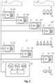
- Fig. 2 illustrates schematically an electronic device 10 for locating a functional disorder at an exemplary spinning and winding section of a spinning mill having arranged a plurality of spinning machines 5, 5′, 5 ⁇ , 5′′′, ... and a plurality of winding machines 7, 7′, 7 ⁇ , ..
- a plurality of roving machines 3, 3′, ... can be arranged for producing roving 4.
- Roving 4 is received at the spinning machines 5, 5 ⁇ , 5 ⁇ , 5′′′, ... for producing yarn delivery bobbins 6 with wound yarn.
- yarn delivery bobbins 6 with wound yarn is received at the winding machines 7, 7 ⁇ , 7 ⁇ , ... for producing yarn bobbins 8.
- the electronic device 10 is configured to receive from the one or more spinning machines 5, 5 ⁇ , 5 ⁇ , 5′′′, ... spinning parameters sp related to the production of yarn delivery bobbins 6.
- the spinning parameters sp can include yarn delivery bobbin identifiers of the produced yarn delivery bobbins 6.
- each yarn delivery bobbin 6 can include an identifier unit id, such as an RFID tag (RFID: Radio Frequency Identifier), or a barcode, wherein the spinning machines 5, 5 ⁇ , 5 ⁇ , 5′′′, ... can be configured to determine a yarn delivery bobbin identifier by reading a unique identification number from the identification unit id as described above.
- RFID Radio Frequency Identifier
- the electronic device 10 can receive the yarn delivery bobbin identifier of a yarn delivery bobbin 6 by respectively controlling and accessing the spinning controller 50.
- the electronic device 10 can access further spinning parameters sp of the yarn delivery bobbin 6 and store the yarn delivery bobbin identifier of the yarn delivery bobbin 6 assigned to the further spinning parameters sp of the yarn delivery bobbin.
- the electronic device 10 can store spinning parameters sp after lapse of a predefined time interval, after production of a predefined amount of yarn, etc.
- the time interval, amount of yarn, etc. may be variable. For example, during a first phase of the production of a yarn delivery bobbin 6, a different time interval, amount of yarn, etc.
- the electronic device 10 may be selected than during a second phase. For example, during an initial phase of the production of a yarn delivery bobbin 6, a smaller time interval may be selected than during an end phase of the production of a yarn delivery bobbin 6.
- the electronic device 10 can have stored different imperfection indices, hairiness values, etc. for different sections of the yarn wound on the yarn delivery bobbin 6.
- the electronic device 10 can have stored spinning parameters sp assigned to yarn and/or sections of yarn wound on the yarn delivery bobbin 6, together with the yarn delivery bobbin identifier of the yarn delivery bobbin 6.
- the spinning parameters sp can include an identification of the spinning machine 5, 5 ⁇ , 5 ⁇ , 5′′′, ..., an identification of the spinning position 51, 52, 51 ⁇ , 52′, ..., etc.
- the electronic device 10 can receive one or more yarn delivery bobbin parameters ydp of the yarn delivery bobbins 6 received in respective winding positions.
- the yarn delivery bobbin parameters ydp can include, for example, a yarn delivery bobbin identifier, etc.
- the electronic device can receive from the winding machines 7, 7′, 7 ⁇ , ... winding parameters wp related to the production of yarn bobbins 8.
- the winding parameters wp can relate to the winding positions of the winding machines 7, 7′, 7 ⁇ , ....
- the electronic device 10 accesses the winding controllers 70 of the winding machine 7, 7′, 7 ⁇ , ... for receiving respective information from the control units 710, 720 of the winding positions 711, 721 of the winding machines 7, 7′, 7 ⁇ , 7′′′, ....
- the electronic device 10 is configured to compare at least one of the winding parameters wp with a level which defines a normal state of the at least one of the winding parameters wp, as described above.
- the electronic device 10 is configured to locate, if the result of the comparison indicates an abnormality, the functional disorder Ic at the spinning and winding section 1 based on respective received spinning parameters sp, winding parameters wp and yarn delivery bobbin parameters ydp.
- the electronic device 10 can locate, on the basis of the yarn delivery bobbin identifier and spinning parameters sp which include spinning positions, the functional disorder at that spinning position.
- the electronic device 10 can locate, on the basis of the yarn delivery bobbin identifiers and spinning parameters sp which include spinning positions, the functional disorder at that winding position.
- the electronic device 10 when the electronic device 10 has located the functional disorder at a particular spinning position, the electronic device 10 can determine further spinning positions producing yarn delivery bobbins 6 with similar spinning parameters sp such as an imperfection index, hairiness, etc. and locate these spinning positions as possible functional disorders even when the winding parameters wp do not yet indicate an abnormality for yarn delivery bobbins 6 produced at these spinning positions.
- similar spinning parameters sp such as an imperfection index, hairiness, etc.
- the yarn delivery bobbin parameters ydp can include parameters such as an imperfection index, a hairiness, etc. determined at the winding machines 7, 7′, 7 ⁇ .... Locating a functional disorder can be based on matching respective spinning parameters sp and yarn delivery bobbin parameters ydp such as an imperfection index, hairiness, etc.
- the spinning parameters sp can be used to identify all spinning positions producing yarn delivery bobbins 6 with a parameter of that particular level, thereby locating functional disorders. For example, a machine parameter may have been wrongly adjusted for a set of spinning positions.
- the yarn delivery bobbin parameters ydp can include parameters such as an imperfection index, a hairiness, etc. determined at the winding machines 7, 7′ 7 ⁇ ,..
- the electronic device 10 can determine for each yarn delivery bobbin 6 a difference between respective spinning parameters sp and yarn delivery bobbin parameters ydp. If the difference is larger than a predefined threshold, transportation of yarn delivery bobbins 6 from the spinning machines 5, 5 ⁇ , 5 ⁇ , 5′′′, ... to the winding machines 7, 7 ⁇ , 7 ⁇ , ... can be located as functional disorder. For example, during transportation, the yarn delivery bobbins 6 may have been exposed to air having a high air humidity level.
- the electronic device 10 may include neural network algorithms, fuzzy logic algorithms, etc. for locating the functional disorder at the spinning and winding section 1 based on respective received spinning parameters sp, winding parameters wp and yarn delivery bobbin parameters ydp.
- Fig. 3 illustrates schematically possible method steps of a method for locating a functional disorder at a spinning and winding section 1 of a spinning mill.
- the spinning and winding section 1 includes one or more spinning machines 5, 5 ⁇ , 5 ⁇ , 5′′′, ... and one or more winding machines 7, 7 ⁇ , 7 ⁇ , ....
- the one or more spinning machines 5, 5 ⁇ , 5 ⁇ , 5′′′, .. are configured to produce a plurality of yarn delivery bobbins 6 with wound yarn.
- the one or more winding machines 7, 7 ⁇ , 7 ⁇ , ... are configured to receive yarn delivery bobbins 6 with wound yarn produced by the one or more spinning machines 5, 5 ⁇ , 5 ⁇ , 5′′′, ... for producing yarn bobbins 8.
- the method includes executing at an electronic device 10 or a computer system the steps of receiving at step S1 from the one or more spinning machines 5, 5 ⁇ , 5 ⁇ , 5′′′, ... spinning parameters sp related to the production of yarn delivery bobbins 6; receiving at step S2 from the one or more winding machines 7, 7 ⁇ , 7 ⁇ , .. winding parameters related to the production of yarn bobbins 8; receiving at step S3 from the one or more winding machines 7, 7 ⁇ , 7 ⁇ , ...
- yarn delivery bobbin parameters ydp related to yarn delivery bobbins 6 received in the one or more winding machines 7, 7′, 7 ⁇ , ...; comparing at step S4 at least one of the winding parameters wp with a level which defines a normal state of the at least one of the winding parameters wp; locating at step S5, if the result of the comparison indicates an abnormality, the functional disorder Ic at the spinning and winding section 1 based on respective received spinning parameters sp, winding parameters wp and yarn delivery bobbin parameters ydp.
- the yarn delivery bobbins 6, 61, ... can relate to spun yarn, which in particular is wound on any type of a carrier.
- the yarn bobbins 8, 81, ... can relate to rewound yarn, which in particular relates to spun yarn which is rewound on any type of a carrier.
Landscapes
- Engineering & Computer Science (AREA)
- Artificial Intelligence (AREA)
- Mechanical Engineering (AREA)
- Textile Engineering (AREA)
- Evolutionary Computation (AREA)
- Physics & Mathematics (AREA)
- Software Systems (AREA)
- Fuzzy Systems (AREA)
- Computer Vision & Pattern Recognition (AREA)
- Medical Informatics (AREA)
- General Physics & Mathematics (AREA)
- Automation & Control Theory (AREA)
- Health & Medical Sciences (AREA)
- Mathematical Physics (AREA)
- Quality & Reliability (AREA)
- Filamentary Materials, Packages, And Safety Devices Therefor (AREA)
- Spinning Or Twisting Of Yarns (AREA)
Abstract
The disclosure relates to an electronic device (10) and a method for locating a functional disorder (Ic) at a spinning and winding section (1) of a spinning mill. The spinning and winding section (1) includes spinning machines (5, 5', 5", 5"', ...) and winding machines (7, 7', 7", ...). The spinning machines (5, 5', 5", 5"', ...) are configured to produce a plurality of yarn delivery bobbins (6) with wound yarn. The winding machines (7, 7', 7", ...) are configured to receive yarn delivery bobbins (6) with wound yarn for producing yarn bobbins (8). The electronic device (10) is configured to: receive from the spinning machines (5, 5', 5", 5"', ...) spinning parameters (sp) related to the production of yarn delivery bobbins (6); receive from the winding machines (7, 7', 7", ...) winding parameters (wp) related to the production of yarn bobbins (8); receive from the winding machines (7, 7', 7", ...) yarn delivery bobbin parameters (ydp) related to yarn delivery bobbins (6) received in the machines (7, 7', 7", ...); compare a winding parameter (wp) with a level which defines a normal state of the winding parameter (wp); locate, if the result of the comparison indicates an abnormality, the functional disorder (Ic) at the spinning and winding section (1) based on respective received spinning parameters (sp), winding parameters (wp) and yarn delivery bobbin parameters (ydp).
Description
- The present disclosure relates to an electronic device for locating a functional disorder at a spinning and winding section of a spinning mill and to a method for locating a functional disorder at a spinning and winding section of a spinning mill.
- Spinning mills include various sections comprising different types of textile machines for converting natural and man-made fibers and their blends into yarns. Spinning mills are designed to produce yarns in a form enabling a proper yarn performance in subsequent manufacturing steps. For this purpose, it is required that the yarn matches predefined quality parameters, and that the yarn is produced in a configuration which is adapted for subsequent manufacturing steps. Quality parameters of yarns may relate to mass, thickness, number of filaments, etc. Configurations of yarns produced by the spinning mill may relate to yarn bobbins, on which a large amount of yarn is wound up for efficient transportation and use.
- A spinning and winding section of a spinning mill may include one or more spinning machines and one or more winding machines.
- A spinning machine includes a plurality of spinning positions. At the spinning positions, roving bobbins are received from upstream textile machines. At the spinning positions, roving is unwound from the roving bobbins, stretched, twisted (spun) and wound as yarn onto a tube forming a yarn delivery bobbin. During the production of the yarn delivery bobbins, yarn parameters can be monitored.
- The winding machines are arranged downstream from the spinning machines and receive the yarn delivery bobbins produced by the spinning machines.
- A winding machine includes a plurality of winding positions. At the winding positions, yarn delivery bobbins which were produced by upstream spinning machines are rewound one after the other onto a cross-wound bobbin. The purpose of rewinding is to produce large yarn bobbins that can be transported and used efficiently. During the rewinding, properties of the yarn can be monitored and compared with predefined quality criteria. If a quality criterion is not met, the defective part of the yarn can be removed. So-called yarn clearing systems are known for this purpose, see e.g.,
WO2012051730 , which enable respective clearing operations. - The yarn bobbins are produced by the winding machines in a configuration which is adapted for subsequent manufacturing steps.
-
EP3305700 discloses yarn winding system which includes an automatic winder configured to wind yarn from a yarn supply bobbin to form a package, and a roving frame and a spinning frame each configured to perform a spinning process at a previous step for the automatic winder. The automatic winder includes a yarn monitoring unit configured to detect a state of the yarn travelling and a transmission unit configured to transmit information on a monitoring result of the yarn monitoring unit to the roving frame and the spinning frame. The roving frame and the spinning frame include a receiving unit, configured to receive the information on the monitoring result of the yarn monitoring unit from the automatic winder. The spinning frame winds yarn to form a yarn supply bobbin. The automatic winder winds the yarn from the yarn supply bobbin to form a package. A bobbin transfer device transfers the yarn supply bobbin from the spinning frame to the automatic winder and transfers an empty bobbin from the automatic winder to the spinning frame using respective trays which include an RF (RF: radio frequency) tag for storing information on the yarn supply bobbin. The bobbin transfer device includes an RF writer for writing information on the RF tag which includes unit identification information for identifying a spinning unit that has formed the yarn supply bobbin and doffing information for identifying timing of doffing. The automatic winder includes an RF reader for reading information written on the RF tag for identifying the spinning unit that has formed the yarn supply bobbin and the timing of doffing. - There may be a need for an electronic device for locating a functional disorder at a spinning and winding section of a spinning mill and for a method for locating a functional disorder at a spinning and winding section of a spinning mill which enable locating the functional disorder both at spinning machines and winding machines, which enable locating the functional disorder quickly, and which provide more flexibility for locating the functional disorder.
- Such a need may be met by the subject-matter of the independent claims. Advantageous embodiments are defined in the dependent claims.
- An aspect of the invention relates to an electronic device for locating a functional disorder at a spinning and winding section of a spinning mill, the spinning and winding section including one or more spinning machines and one or more winding machines, the one or more spinning machines being configured to produce a plurality of yarn delivery bobbins with wound yarn, the one or more winding machines being configured to receive yarn delivery bobbins with wound yarn produced by the one or more spinning machines for producing yarn bobbins, the electronic device being configured to: receive from the one or more spinning machines spinning parameters related to the production of yarn delivery bobbins; receive from the one or more winding machines winding parameters related to the production of yarn bobbins; receive from the one or more winding machines yarn delivery bobbin parameters related to yarn delivery bobbins received in the one or more winding machines; compare at least one of the winding parameters with a level which defines a normal state of the at least one of the winding parameters; locate, if the result of the comparison indicates an abnormality, the functional disorder at the spinning and winding section based on respective received spinning parameters, winding parameters and yarn delivery bobbin parameters. Based on an abnormality detected at a winding machine, a functional disorder can be located in the spinning and winding section including spinning machines and winding machines. The spinning parameters, winding parameters, yarn delivery bobbin parameters can be received via respective signal lines, such as via wired or wireless computer networks. For example, a number of winding errors exceeding a predefining limit may indicate an abnormality in the spinning and winding section. The abnormality indicates that there is a functional disorder in the spinning and winding section. The location of the functional disorder is determined based on spinning parameters, winding parameters and yarn delivery bobbin parameters. For example, in case of an excessive number of winding errors, the spinning parameters and yarn delivery bobbin parameters can be used to determine whether the functional disorder is located in the winding machine or in a spinning machine. For example, winding parameters may indicate no other abnormality beside the excessive number of winding errors, while yarn bobbin parameters indicate that the abnormality of an excessive number of winding errors occurs when yarn delivery bobbins are received in the winding machine which were produced at a particular spinning position, wherein spinning parameters such as a rotating speed at that spinning position may be at an abnormal level, thereby locating that spinning position as the functional disorder of the spinning and winding section. This simple example may not be construed as limiting the scope of the claims, because the person skilled in the art readily can define various scenarios for locating the functional disorder at the spinning and winding section based on respective received spinning parameters, winding parameters and yarn delivery bobbin parameters.
- Yarn delivery bobbins typically have wound spun yarn on a suitable carrier, such as wound on a tube. A tube can be adapted for carrying a relatively small amount of yarn. A yarn delivery bobbin having a relatively limited amount of yarn wound on a tube as a carrier may be designated as cop. However according to one aspect of the invention — which can also be considered to be an independent inventive concept — yarn delivery bobbins may also relate to relatively large cross-wound bobbins produced by e.g. rotor spinning machines or airjet spinning machines, wherein when received in the winding machine the spun yarn of a single cross-wound bobbin is rewound onto a respective (cross-wound) yarn bobbin. This may for example be done for improving the quality of the yarn by making use, for example, of a yarn cleaning device, a splice device, etc. of the winding machine, thereby enabling different applications so, for example, for subsequent dyeing of the yarn or for use on special weaving machines that require rapid removal of the yarn from the cross-wound package. Such rewinding may also be necessary to obtain bobbins with particularly high quality yarn.
- In some embodiments, the functional disorder relates to a spinning machine and/or a winding machine. The functional disorder can be located either at a spinning machine or at a winding machine, or the functional disorder can be located at a combination of a spinning machine and a winding machine.
- In some embodiments, locating the functional disorder includes evaluating spinning parameters and yarn delivery bobbin parameters and depending on the result of the evaluation, locating the functional disorder at a winding machine or at a spinning machine. After detecting an abnormality at a winding machine, the functional disorder can be located by evaluating the spinning parameters and yarn delivery bobbin parameters. For example, the spinning parameters may relate to spinning positions having a particular rotation speed, and the yarn bobbin parameters may indicate yarn delivery bobbins received in a winding machine which were produced with that particular rotation speed. If this particular rotation speed has a normal level, the functional disorder of the spinning and winding section can be located at the winding machine. Otherwise, the functional disorder can be located at a spinning machine with spinning positions of the particular rotation speed.
- In some embodiments, the spinning parameters and/or the yarn delivery bobbin parameters relate to a yarn delivery bobbin identifier, an imperfection index, a hairiness, a variation coefficient of yarn mass, a variation index of yarn diameter, a number of thick places per unit of length, a number of thin places per unit of length, a number of periodic yarn faults per unit of length, a number of yarn count variants per unit of length, and/or a number of foreign materials per unit of length. Spinning parameters and/or yarn delivery bobbin parameters which are widely available in spinning and winding sections can be used for locating a functional disorder.
- In some embodiments, the spinning parameters relate to one or more of a doffing time, a spindle speed, a ring traveler speed, a number of yarn breaks per unit of time, an air temperature, and an air humidity. Spinning parameters which are widely available in spinning and winding sections can be used for locating a functional disorder.
- In some embodiments, the winding parameters relate to one or more of a yarn tension, a number of clearing operations, a consumption of energy, and a number of produced yarn bobbins per unit of time. Winding parameters which are widely available in spinning and winding sections can be used for locating a functional disorder.
- In some embodiments, the electronic device is further configured to receive spinning parameters, winding parameters and yarn delivery bobbin parameters by accessing a controller of a spinning machine and a controller of a winding machine. The electronic device can be easily adapted to existing spinning and winding sections.
- In some embodiments locating the functional disorder is based on one or more of a neural network algorithm and a fuzzy logic algorithm. Powerful tools can be used for locating a functional disorder in a spinning and winding section.
- In some embodiments, the electronic device is further configured to signal the location of the functional disorder to one or more of the spinning machines, the winding machines and a computer display. The electronic device can support automatic-, semi-automatic or manual correction of a functional disorder in a spinning and winding section. Signaling the location to a spinning machine and/or a winding machine, such as a respective controller, can support automatic correction, for example by activation of a respective robot. Signaling the location of a functional disorder to a computer display can support semi-automatic or manual correction.
- The invention is also directed to a computer system for putting into practice an electronic device as defined above, the computer system comprising one or more computers, the one or more computers preferably comprising a graphical user interface. The computers can relate to machine controllers, desktop computers, notebook computers, tablet computers, smartphones, etc. The graphical user interface can relate to a display, a touchscreen, a display with keyboard and mouse, etc. The computer system can include existing controllers of spinning machines and winding machines, existing controllers and/or computers of a spinning mill, etc.
- The invention also relates to a method for locating a functional disorder at a spinning and winding section of a spinning mill, the spinning and winding section including one or more spinning machines and one or more winding machines, the one or more spinning machines being configured to produce a plurality of yarn delivery bobbins with wound yarn, the one or more winding machines being configured to receive yarn delivery bobbins with wound yarn produced by the one or more spinning machines for producing yarn bobbins, wherein the method includes the steps executed by an electronic device or a computer system of: receiving from the one or more spinning machines spinning parameters related to the production of yarn delivery bobbins; receiving from the one or more winding machines winding parameters related to the production of yarn bobbins; receiving from the one or more winding machines yarn delivery bobbin parameters related to yarn delivery bobbins received in the one or more winding machines; comparing at least one of the winding parameters with a level which defines a normal state of the at least one of the winding parameters; locating, if the result of the comparison indicates an abnormality, the functional disorder at the spinning and winding section based on respective received spinning parameters, winding parameters and yarn delivery bobbin parameters.
- In some embodiments, the functional disorder relates to one of a spinning machine and a winding machine.
- In some embodiments, locating the functional disorder includes evaluating spinning parameters and yarn delivery bobbin parameters and depending on the result of the evaluation, locating the functional disorder at a winding machine or at a spinning machine.
- In some embodiments, locating the functional disorder includes evaluating spinning parameters and yarn delivery bobbin parameters and depending on the result of the evaluation, locating the functional disorder at a winding machine or at a spinning machine.
- In some embodiments, the method further includes signaling the location of the functional disorder to one or more of the spinning machines, the winding machines and a computer display.
- The invention will be better understood with the aid of the description of an embodiment given by way of example an illustrated by the figures, in which:
-
Fig. 1 illustrates schematically an electronic device for locating a functional disorder at an exemplary spinning and winding section of a spinning mill having arranged a spinning machine and a winding machine; -
Fig. 2 illustrates schematically an electronic device locating a functional disorder at an exemplary spinning and winding section of a spinning mill having arranged a plurality of spinning machines and a plurality of winding machines; -
Fig. 3 illustrates schematically possible method steps of a method for locating a functional disorder at a spinning and winding section of a spinning mill. - The foregoing summary, as well as the following detailed description of the preferred embodiments, is better understood when read in conjunction with the appended drawings. For the purposes of illustrating the invention, an embodiment that is presently preferred, in which like numerals represent similar parts throughout the several views of the drawings, it being understood, however, that the invention is not limited to the specific methods and instrumentalities disclosed.
-
Fig. 1 illustrates schematically anelectronic device 10 for locating a functional disorder at an exemplary spinning and windingsection 1 of a spinning mill having arranged a spinningmachine 5 and a windingmachine 7. In typical spinning mills, the spinning and windingsection 1 includes a plurality of spinning machines and a plurality of winding machines (not illustrated inFig. 1 ). - As illustrated in
Fig. 1 , the spinningmachine 5 is arranged upstream from the windingmachine 7. Correspondingly, the windingmachine 7 is arranged downstream from the spinningmachine 5. In spinning and winding sections of typical spinning mills, a plurality of spinning machines and a plurality of winding machines are arranged respectively. - The spinning
machine 5 may relate to a ring spinning machine. However, within the context of the present application, the spinningmachine 5 can also relate to another type of spinning machine producing yarn sections with typically a relatively limited length, which are then to be rewound by a winding machine to form bobbins comprising yarn of sufficient length. For example, the spinningmachine 5 may also be a pot spinning machine. However, as has also been described herein, according to a variation of the invention, a spinning machine may also be a rotor spinning machine or airjet spinning machine. - The spinning
machine 5 receives roving 4, which was produced by an upstream roving machine 3 (typically, a plurality of roving machines is arranged), and produces yarn delivery bobbins 6 (carriers) with wound yarn. The spinningmachine 5 includes a plurality of spinningpositions position position spinning unit spinning unit position yarn delivery bobbins yarn delivery bobbins - The winding
machine 7 receivesyarn delivery bobbins 6, which were produced by the upstream spinning machine 5 (typically, a plurality of upstream spinning machines is arranged), and producesyarn bobbins 8. The windingmachine 7 includes a plurality of windingpositions position yarn delivery bobbins unit unit position yarn delivery bobbins Fig. 1 , at each windingposition yarn delivery bobbins position yarn delivery bobbins yarn bobbins positions - Typically, the number of spinning positions 51, 52, 53 of a spinning
machine 5 and the number of windingpositions machine 7 is large and strongly exceeds the small number of positions schematically illustrated inFig. 1 . - As illustrated in
Fig. 1 , the spinningmachine 5 includes a spinningcontroller 50 for controlling operation of the spinningmachine 5. The spinningcontroller 50 is connected viasignal line 5s withcontrol units units control units controller 50 control signals via thesignal line 5s for controlling operation of the spinningunits yarn delivery bobbins yarn delivery bobbins yarn delivery bobbins units 511, 512, 513, such as a spindle speed, drafting rate, a mode of movement of a ring bench and/or of a spindle bench, a rotation speed of a spinning pot, a rotation speed of a driven spinning ring, a rotation speed of a controlled rotating spinning ring, a ring traveler speed, etc. Control signals can also be used to control an auxiliary module of a spinning machine. For example, an auxiliary module may be a spindle monitor of a spinning machine or a service robot of a spinning machine. For example, by means of a control signal, a service robot can be instructed to drive to a specific spinning position and carry out a more detailed analysis of the spinning position and/or carry out certain maintenance actions (e.g. replace a ring traveler or clean the rollers of a drafting system). Thecontrol units controller 50 via thesignal line 5s. Monitor signals may relate to the spinningunits units yarn delivery bobbins - As illustrated in
Fig. 1 , the windingmachine 7 includes a windingcontroller 70 for controlling operation of the windingmachine 7. The windingcontroller 70 is connected viasignal line 7s withcontrol units units positions control units controller 70 control signals via thesignal line 7s for controlling operation of the windingunits yarn bobbins yarn delivery bobbins yarn bobbins yarn bobbin yarn bobbins yarn bobbin units control units controller 70 via thesignal line 7s. Monitor signals may relate to the windingunits yarn delivery bobbins yarn delivery bobbins yarn bobbins yarn bobbins - A
yarn delivery bobbin 6 can include an identifier unit, such as an RFID tag (RFID: Radio Frequency Identifier), having stored a yarn delivery bobbin identifier in the form of a unique identification number, for example. At the spinning positions 51, 52, 53 of the spinningmachine 5 and at the windingpositions machine 7, reader units, such as an RFID reader, can be arranged for determining yarn delivery bobbin identifiers ofyarn delivery bobbins 6 arranged at the spinning positions 51, 52, 53 respectively at the windingpositions yarn delivery bobbin 6. - As indicated in
Fig. 1 by respective reference numerals, the spinningmachine 5 produces yarn delivery bobbins withreference numerals machine 7 has received yarn delivery bobbins havingdifferent reference numerals - As illustrated in
Fig. 1 , anelectronic device 10 is arranged. Theelectronic device 10 is connected viasignal line 1s to the spinningcontroller 50 of the spinningmachine 5 and to the windingcontroller 70 of the windingmachine 7. Typically, the electronic device is connected to a plurality of spinning machines and to a plurality of winding machines. As indicated inFig. 1 , theelectronic device 10 may be connected viasignal line 1s to further upstream machines, such as theroving machine 3. - The
electronic device 10, the spinningcontroller 50, the windingcontroller 70, thesignal lines electronic device 10 may relate to a control and monitoring device of a spinning mill. - The roving 4 respectively the
yarn delivery bobbins 6 may be transported automatically, semi-automatically or manually from theroving machine 3 to the spinning machine 5 (or a plurality of such machines) respectively from the spinningmachine 5 to the winding machine 7 (or a plurality of such machines). Theyarn bobbins 8 may be transported away from the windingmachine 7 automatically, semi-automatically or manually. - The
electronic device 10 is configured to receive from the spinningmachine 5 spinning parameters sp related to the production ofyarn delivery bobbins 6. For this purpose, the spinningcontroller 50 transmits spinning parameters sp to theelectronic device 10, for example, upon request by theelectronic device 10, by accessing respective information of thecontrol units units - The
electronic device 10 is configured to receive from the windingmachine 7 winding parameters wp related to the production ofyarn bobbins 8. For this purpose, the windingcontroller 70 transmits winding parameters wp to theelectronic device 10, for example, upon request by theelectronic device 10, by accessing respective information of thecontrol units units - The
electronic device 10 is configured to receive yarn delivery bobbin parameters ydp related toyarn delivery bobbins 6 received in the windingmachine 7. For this purpose, the windingcontroller 70 transmits yarn delivery bobbin parameters ydp to theelectronic device 10, for example, upon request by theelectronic device 10, by accessing respective information of thecontrol units units - The
electronic device 10 is configured to compare at least one of the winding parameters wp with a level which defines a normal state of the at least one winding parameter wp. For example, comparison may occur repeatedly after lapse of predefined time intervals. For example, a number of clearing operations per unit of time, a number of winding errors, etc. can be compared with a level which defines a normal number of clearing operations, winding errors, etc. per unit of time. - The
electronic device 10 is configured to locate, if the result of the comparison indicates an abnormality, the functional disorder Ic at the spinning and windingsection 1 based on respective received spinning parameters sp, winding parameters wp and yarn delivery bobbin parameters ydp. For example, a number of clearing operations below a predefined limit may indicate normal operation. For example, a number of clearing operations above a predefined limit may indicate an abnormality. In case of an abnormality, the electronic device locates the functional disorder based on the spinning parameters sp, winding parameters wp, and yarn delivery bobbin parameters ydp. For example, winding parameters wp can include an identification of the windingposition 71 with the abnormal number of clearings. For example, the yarn delivery bobbin parameters ydp can include an identification of theyarn delivery bobbins 6 received in the windingposition 71 with the abnormal number of clearings. For example, based on their identifications, an imperfection index of theyarn delivery bobbins 6 received in the windingposition 71. For example, if the imperfection index of theyarn delivery bobbins 6 received in the windingposition 71 has a normal state, theelectronic device 10 can be configured to locate the windingposition 71 as the location of the functional disorder at the spinning and windingsection 1. Otherwise, if the imperfection index of theyarn delivery bobbins 6 received in the windingposition 71 have an abnormal state, for example, theelectronic device 10 can be configured to determine an identification of ayarn delivery bobbin 6 received in the windingposition 71, to lookup based on the identification of theyarn delivery bobbin 6 thespinning position 52 which produced theyarn delivery bobbin 6, and to locate thespinning position 52 as the location of the functional disorder at the spinning and windingsection 1. -
Fig. 2 illustrates schematically anelectronic device 10 for locating a functional disorder at an exemplary spinning and winding section of a spinning mill having arranged a plurality ofspinning machines machines spinning machines roving machines Roving 4 is received at thespinning machines 5, 5ʹ, 5ʺ, 5‴, ... for producingyarn delivery bobbins 6 with wound yarn.yarn delivery bobbins 6 with wound yarn is received at the windingmachines 7, 7ʹ, 7ʺ, ... for producingyarn bobbins 8. - As described above, the
electronic device 10 is configured to receive from the one ormore spinning machines 5, 5ʹ, 5ʺ, 5‴, ... spinning parameters sp related to the production ofyarn delivery bobbins 6. The spinning parameters sp can include yarn delivery bobbin identifiers of the producedyarn delivery bobbins 6. - For this purpose, for example, as illustrated in
Fig. 2 , eachyarn delivery bobbin 6 can include an identifier unit id, such as an RFID tag (RFID: Radio Frequency Identifier), or a barcode, wherein thespinning machines 5, 5ʹ, 5ʺ, 5‴, ... can be configured to determine a yarn delivery bobbin identifier by reading a unique identification number from the identification unit id as described above. - The
electronic device 10 can receive the yarn delivery bobbin identifier of ayarn delivery bobbin 6 by respectively controlling and accessing the spinningcontroller 50. Theelectronic device 10 can access further spinning parameters sp of theyarn delivery bobbin 6 and store the yarn delivery bobbin identifier of theyarn delivery bobbin 6 assigned to the further spinning parameters sp of the yarn delivery bobbin. During production of ayarn delivery bobbin 6, theelectronic device 10 can store spinning parameters sp after lapse of a predefined time interval, after production of a predefined amount of yarn, etc. The time interval, amount of yarn, etc. may be variable. For example, during a first phase of the production of ayarn delivery bobbin 6, a different time interval, amount of yarn, etc. may be selected than during a second phase. For example, during an initial phase of the production of ayarn delivery bobbin 6, a smaller time interval may be selected than during an end phase of the production of ayarn delivery bobbin 6. For example, in accordance with the yarn wound on ayarn delivery bobbin 6, theelectronic device 10 can have stored different imperfection indices, hairiness values, etc. for different sections of the yarn wound on theyarn delivery bobbin 6. Thus, for each producedyarn delivery bobbin 6, theelectronic device 10 can have stored spinning parameters sp assigned to yarn and/or sections of yarn wound on theyarn delivery bobbin 6, together with the yarn delivery bobbin identifier of theyarn delivery bobbin 6. The spinning parameters sp can include an identification of the spinningmachine 5, 5ʹ, 5ʺ, 5‴, ..., an identification of thespinning position - Accordingly, when
yarn delivery bobbins 6 are received in windingmachines electronic device 10 can receive one or more yarn delivery bobbin parameters ydp of theyarn delivery bobbins 6 received in respective winding positions. The yarn delivery bobbin parameters ydp can include, for example, a yarn delivery bobbin identifier, etc. Furthermore, the electronic device can receive from the windingmachines yarn bobbins 8. The winding parameters wp can relate to the winding positions of the windingmachines - For this purpose, for example, the
electronic device 10 accesses the windingcontrollers 70 of the windingmachine control units positions machines - The
electronic device 10 is configured to compare at least one of the winding parameters wp with a level which defines a normal state of the at least one of the winding parameters wp, as described above. - The
electronic device 10 is configured to locate, if the result of the comparison indicates an abnormality, the functional disorder Ic at the spinning and windingsection 1 based on respective received spinning parameters sp, winding parameters wp and yarn delivery bobbin parameters ydp. - For example, for
yarn delivery bobbins 6 produced at a particular spinning position, an abnormal state may result when theseyarn delivery bobbins 6 are received in any of the winding positions. Accordingly, theelectronic device 10 can locate, on the basis of the yarn delivery bobbin identifier and spinning parameters sp which include spinning positions, the functional disorder at that spinning position. - For example, for a particular winding position, an abnormal state may result when
yarn delivery bobbins 6 are received, irrespective from the spinning position. Accordingly, theelectronic device 10 can locate, on the basis of the yarn delivery bobbin identifiers and spinning parameters sp which include spinning positions, the functional disorder at that winding position. - For example, when the
electronic device 10 has located the functional disorder at a particular spinning position, theelectronic device 10 can determine further spinning positions producingyarn delivery bobbins 6 with similar spinning parameters sp such as an imperfection index, hairiness, etc. and locate these spinning positions as possible functional disorders even when the winding parameters wp do not yet indicate an abnormality foryarn delivery bobbins 6 produced at these spinning positions. - For example, the yarn delivery bobbin parameters ydp can include parameters such as an imperfection index, a hairiness, etc. determined at the winding
machines yarn delivery bobbins 6 having a parameter of a particular level, such as a particular imperfection index, hairiness, etc. result in an abnormal state, the spinning parameters sp can be used to identify all spinning positions producingyarn delivery bobbins 6 with a parameter of that particular level, thereby locating functional disorders. For example, a machine parameter may have been wrongly adjusted for a set of spinning positions. - For example, the yarn delivery bobbin parameters ydp can include parameters such as an imperfection index, a hairiness, etc. determined at the winding
machines electronic device 10 can determine for each yarn delivery bobbin 6 a difference between respective spinning parameters sp and yarn delivery bobbin parameters ydp. If the difference is larger than a predefined threshold, transportation ofyarn delivery bobbins 6 from thespinning machines 5, 5ʹ, 5ʺ, 5‴, ... to the windingmachines 7, 7ʹ, 7ʺ, ... can be located as functional disorder. For example, during transportation, theyarn delivery bobbins 6 may have been exposed to air having a high air humidity level. - The
electronic device 10 may include neural network algorithms, fuzzy logic algorithms, etc. for locating the functional disorder at the spinning and windingsection 1 based on respective received spinning parameters sp, winding parameters wp and yarn delivery bobbin parameters ydp. -
Fig. 3 illustrates schematically possible method steps of a method for locating a functional disorder at a spinning and windingsection 1 of a spinning mill. The spinning and windingsection 1 includes one ormore spinning machines 5, 5ʹ, 5ʺ, 5‴, ... and one or more windingmachines 7, 7ʹ, 7ʺ, .... The one ormore spinning machines 5, 5ʹ, 5ʺ, 5‴, .. are configured to produce a plurality ofyarn delivery bobbins 6 with wound yarn. The one or more windingmachines 7, 7ʹ, 7ʺ, ... are configured to receiveyarn delivery bobbins 6 with wound yarn produced by the one ormore spinning machines 5, 5ʹ, 5ʺ, 5‴, ... for producingyarn bobbins 8. The method includes executing at anelectronic device 10 or a computer system the steps of receiving at step S1 from the one ormore spinning machines 5, 5ʹ, 5ʺ, 5‴, ... spinning parameters sp related to the production ofyarn delivery bobbins 6; receiving at step S2 from the one or more windingmachines 7, 7ʹ, 7ʺ, .. winding parameters related to the production ofyarn bobbins 8; receiving at step S3 from the one or more windingmachines 7, 7ʹ, 7ʺ, ... yarn delivery bobbin parameters ydp related toyarn delivery bobbins 6 received in the one or more windingmachines section 1 based on respective received spinning parameters sp, winding parameters wp and yarn delivery bobbin parameters ydp. - The
yarn delivery bobbins yarn bobbins -
- 1
- spinning and winding section of a spinning mill
- 10
- electronic device
- 1s, 5s, 7s
- signal lines
- id
- identifier unit of roving, yarn delivery bobbins, yarn bobbins
- 3, 3'
- roving machines
- 4, 41, 42, 43
- roving
- 5, 5′, 5ʺ, 5‴
- spinning machines
- 50
- spinning controller
- 51, 52, 53
- spinning positions
- 511, 521, 531
- spinning units
- 510, 520, 530
- control units of spinning units
- 6, 61, 62, 63, 65, 68
- yarn delivery bobbins with wound yarn
- 7, 7′, 7ʺ, 7‴
- winding machines
- 70
- winding controller
- 71, 72, 73
- winding positions
- 711, 721, 731
- winding units
- 710, 720, 730
- control units of winding units
- 8, 81, 82
- yarn bobbins
- sp
- spinning parameters
- wp
- winding parameters
- ydp
- yarn delivery bobbin parameters
- Ic
- location of the functional disorder
Claims (15)
- An electronic device (10) for locating a functional disorder (Ic) at a spinning and winding section (1) of a spinning mill, the spinning and winding section (1) including one or more spinning machines (5, 5', 5ʺ, 5‴, ...) and one or more winding machines (7, 7ʹ, 7ʺ, ...), the one or more spinning machines (5, 5′, 5ʺ, 5‴, ...) being configured to produce a plurality of yarn delivery bobbins (6) with wound yarn, the one or more winding machines (7, 7′, 7ʺ, ...) being configured to receive yarn delivery bobbins (6) with wound yarn produced by the one or more spinning machines (5, 5′, 5ʺ, 5‴, ...) for producing yarn bobbins (8), the electronic device (10) being configured to:receive from the one or more spinning machines (5, 5′, 5ʺ, 5‴, ...) spinning parameters (sp) related to the production of yarn delivery bobbins (6);receive from the one or more winding machines (7, 7′, 7ʺ, ...) winding parameters (wp) related to the production of yarn bobbins (8);receive from the one or more winding machines (7, 7′, 7ʺ, ...) yarn delivery bobbin parameters (ydp) related to yarn delivery bobbins (6) received in the one or more winding machines (7, 7′, 7ʺ, ...);compare at least one of the winding parameters (wp) with a level which defines a normal state of the at least one of the winding parameters (wp);locate, if the result of the comparison indicates an abnormality, the functional disorder (Ic) at the spinning and winding section (1) based on respective received spinning parameters (sp), winding parameters (wp) and yarn delivery bobbin parameters (ydp).
- The electronic device (10) of claim 1, wherein the functional disorder relates to one of a spinning machine (5, 5′, 5ʺ, 5‴, ...) and a winding machine (7, 7′, 7ʺ, ...).
- The electronic device (10) of claim 1 or 2, wherein locating the functional disorder (Ic) includes evaluating spinning parameters (sp) and yarn delivery bobbin parameters (ydp) and depending on the result of the evaluation, locating the functional disorder (Ic) at a winding machine (7, 7′, 7ʺ, ...) or at a spinning machine (5, 5′, 5ʺ, 5‴, ...).
- The electronic device (10) of one of claims 1 to 3, wherein the spinning parameters (sp) and/or the yarn delivery bobbin parameters (ydp) relate to one or more of a yarn delivery bobbin identifier, an imperfection index, a hairiness, a variation coefficient of yarn mass, a variation index of yarn diameter, a number of thick places per unit of length, a number of thin places per unit of length, a number of periodic yarn faults per unit of length, a number of yarn count variants per unit of length, and a number of foreign materials per unit of length.
- The electronic device (10) of one of claims 1 to 4, wherein the spinning parameters (sp) relate to one or more of a doffing time, a spindle speed, a ring traveler speed, a number of yarn breaks per unit of time, an air temperature, and an air humidity.
- The electronic device (10) of one of claims 1 to 5, wherein the winding parameters (wp) relate to one or more of a yarn tension, a number of clearing operations, a consumption of energy, and a number of produced yarn bobbins per unit of time.
- The electronic device (10) of one of claims 1 to 6, further configured to receive spinning parameters (sp), winding parameters (wp) and yarn delivery bobbin parameters (ydp) by accessing a controller (50) of a spinning machine (5, 5′, 5ʺ, 5‴, ...) and a controller (70) of a winding machine (7, 7′, 7ʺ, 7‴).
- The electronic device (10) of one of claims 1 to 7, wherein locating the functional disorder (Ic) is based on one or more of a neural network algorithm and a fuzzy logic algorithm.
- The electronic device (10) of one of claims 1 to 8, further configured to signal the location of the functional disorder (Ic) to one or more of the spinning machines (5, 5′, 5ʺ, 5‴, ...), the winding machines (7, 7′, 7ʺ, ...) and a computer display.
- A computer system for putting into practice an electronic device (10) according to one of claims 1 to 9, the computer system comprising one or more computers, the one or more computers preferably comprising a graphical user interface.
- A method for locating a functional disorder (Ic) at a spinning and winding section (1) of a spinning mill, the spinning and winding section (1) including one or more spinning machines (5, 5′, 5ʺ, 5‴, ...) and one or more winding machines (7, 7′, 7ʺ, ...), the one or more spinning machines (5, 5′, 5ʺ, 5‴, ...) being configured to produce a plurality of yarn delivery bobbins (6) with wound yarn, the one or more winding machines (7, 7′, 7ʺ, ...) being configured to receive yarn delivery bobbins (6) with wound yarn produced by the one or more spinning machines (5, 5′, 5ʺ, 5‴, ...) for producing yarn bobbins (8), wherein the method includes the steps executed by an electronic device (10) or a computer system of:receiving (S1) from the one or more spinning machines (5, 5′, 5ʺ, 5‴, ...) spinning parameters (sp) related to the production of yarn delivery bobbins (6);receiving (S2) from the one or more winding machines (7, 7′, 7ʺ, ...) winding parameters (wp) related to the production of yarn bobbins (8);receiving (S3) from the one or more winding machines (7, 7′, 7ʺ, ...) yarn delivery bobbin parameters (ydp) related to yarn delivery bobbins (6) received in the one or more winding machines (7, 7′, 7ʺ, ...);comparing (S4) at least one of the winding parameters (wp) with a level which defines a normal state of the at least one of the winding parameters (wp);locating (S5), if the result of the comparison indicates an abnormality, the functional disorder (Ic) at the spinning and winding section (1) based on respective received spinning parameters (sp), winding parameters (wp) and yarn delivery bobbin parameters (ydp).
- The method of claim 12, wherein the functional disorder relates to one of a spinning machine (5, 5′, 5ʺ, 5‴, ...) and a winding machine (7, 7′, 7ʺ, ...).
- The method of claim 11 or 12, wherein locating the functional disorder (Ic) includes evaluating spinning parameters and yarn delivery bobbin parameters and depending on the result of the evaluation, locating the functional disorder at a winding machine (7, 7ʹ, 7ʺ, ...) or at a spinning machine (5, 5′, 5ʺ, 5‴, ...).
- The method of one of claims 11 to 13, wherein locating the functional disorder (Ic) is based on one or more of a neural network algorithm and a fuzzy logic algorithm..
- The method of one of claims 11 to 14, further including signaling the location of the functional disorder (Ic) to one or more of the spinning machines (5, 5′, 5ʺ, 5‴, ...), the winding machines (7, 7′, 7ʺ, ...) and a computer display.
Priority Applications (6)
| Application Number | Priority Date | Filing Date | Title |
|---|---|---|---|
| EP21201596.0A EP4163242A1 (en) | 2021-10-08 | 2021-10-08 | An electronic device for locating a functional disorder at a spinning and winding section of a spinning mill and a method for locating the same |
| US18/699,008 US20250236994A1 (en) | 2021-10-08 | 2022-09-05 | An electronic device for locating a functional disorder within a spinning and winding section of a spinning mill and a method for locating the same |
| CN202280081545.2A CN118401455A (en) | 2021-10-08 | 2022-09-05 | Electronic device for locating a functional disorder in a spinning and winding section of a spinning mill and method for locating the functional disorder |
| JP2024521094A JP2024536434A (en) | 2021-10-08 | 2022-09-05 | Electronic device for locating malfunctions in the spinning and winding section of a spinning mill and method for locating malfunctions in the spinning and winding section of a spinning mill - Patents.com |
| EP22773317.7A EP4412937A1 (en) | 2021-10-08 | 2022-09-05 | An electronic device for locating a functional disorder within a spinning and winding section of a spinning mill and a method for locating the same |
| PCT/IB2022/058333 WO2023057835A1 (en) | 2021-10-08 | 2022-09-05 | An electronic device for locating a functional disorder within a spinning and winding section of a spinning mill and a method for locating the same |
Applications Claiming Priority (1)
| Application Number | Priority Date | Filing Date | Title |
|---|---|---|---|
| EP21201596.0A EP4163242A1 (en) | 2021-10-08 | 2021-10-08 | An electronic device for locating a functional disorder at a spinning and winding section of a spinning mill and a method for locating the same |
Publications (1)
| Publication Number | Publication Date |
|---|---|
| EP4163242A1 true EP4163242A1 (en) | 2023-04-12 |
Family
ID=78086291
Family Applications (2)
| Application Number | Title | Priority Date | Filing Date |
|---|---|---|---|
| EP21201596.0A Withdrawn EP4163242A1 (en) | 2021-10-08 | 2021-10-08 | An electronic device for locating a functional disorder at a spinning and winding section of a spinning mill and a method for locating the same |
| EP22773317.7A Pending EP4412937A1 (en) | 2021-10-08 | 2022-09-05 | An electronic device for locating a functional disorder within a spinning and winding section of a spinning mill and a method for locating the same |
Family Applications After (1)
| Application Number | Title | Priority Date | Filing Date |
|---|---|---|---|
| EP22773317.7A Pending EP4412937A1 (en) | 2021-10-08 | 2022-09-05 | An electronic device for locating a functional disorder within a spinning and winding section of a spinning mill and a method for locating the same |
Country Status (5)
| Country | Link |
|---|---|
| US (1) | US20250236994A1 (en) |
| EP (2) | EP4163242A1 (en) |
| JP (1) | JP2024536434A (en) |
| CN (1) | CN118401455A (en) |
| WO (1) | WO2023057835A1 (en) |
Citations (5)
| Publication number | Priority date | Publication date | Assignee | Title |
|---|---|---|---|---|
| US5100073A (en) * | 1990-01-29 | 1992-03-31 | W. Schlafhorst Ag & Co. | Automatic textile winding apparatus |
| WO2012051730A1 (en) | 2010-10-19 | 2012-04-26 | Uster Technologies Ag | Yarn clearer and method for clearing yarn |
| DE102016007779A1 (en) * | 2016-06-24 | 2017-12-28 | Saurer Germany Gmbh & Co. Kg | Method for monitoring the proper functioning of the spinning stations of a ring spinning machine |
| EP3305700A1 (en) | 2015-06-05 | 2018-04-11 | Murata Machinery, Ltd. | Yarn winding system, automatic winder, spinning frame and yarn winding method |
| US20210148012A1 (en) * | 2018-05-28 | 2021-05-20 | Uster Technologies Ag | Ring spinning system and method for operating |
Family Cites Families (12)
| Publication number | Priority date | Publication date | Assignee | Title |
|---|---|---|---|---|
| US5182900A (en) * | 1989-12-23 | 1993-02-02 | W. Schlafhorst Ag & Co. | Method and apparatus for checking the operation of a pneumatic splicer |
| DE4335459C2 (en) * | 1993-10-18 | 1999-12-02 | Rieter Ingolstadt Spinnerei | Spinning station fault notifier and qualifier |
| CH686779A5 (en) * | 1993-10-29 | 1996-06-28 | Luwa Ag Zellweger | Apparatus for checking the winding quality of yarn packages and use of the device at a spooling or spinning machine. |
| DE19905860A1 (en) * | 1999-02-12 | 2000-08-17 | Schlafhorst & Co W | Method for operating a work station of a textile machine producing cross-wound bobbins |
| DE50104822D1 (en) * | 2000-11-08 | 2005-01-20 | Rieter Ag Maschf | Control of spinning stations in a spinning machine |
| DE102012108380A1 (en) * | 2012-06-19 | 2013-12-19 | Maschinenfabrik Rieter Ag | Air-jet spinning machine and method of operating the same |
| DE102013102770A1 (en) * | 2013-03-19 | 2014-09-25 | Maschinenfabrik Rieter Ag | Spinning a spinning machine and method for operating the same |
| WO2016016739A1 (en) * | 2014-07-31 | 2016-02-04 | MARZOLI MACHINES TEXTILE S.r.l. | System for monitoring physical parameters of textile machinery and method of predictive maintenance |
| DE102018112797A1 (en) * | 2018-05-29 | 2019-12-05 | Maschinenfabrik Rieter Ag | Method for determining operating states of a textile machine and a textile machine |
| CZ2019196A3 (en) * | 2019-03-29 | 2020-10-07 | Rieter Cz S.R.O. | Non-contact optical detection method of yarn at the textile machine workplace for yarn production, optical yarn sensor and textile machine |
| ES2917375T3 (en) * | 2020-04-30 | 2022-07-08 | Rieter Ag Maschf | Device and method for detecting a failure in a spinning machine and for estimating one or more sources of the failure |
| EP3960918A1 (en) * | 2020-08-31 | 2022-03-02 | Maschinenfabrik Rieter AG | Operating device for a textile machine and method for operating a textile machine |
-
2021
- 2021-10-08 EP EP21201596.0A patent/EP4163242A1/en not_active Withdrawn
-
2022
- 2022-09-05 JP JP2024521094A patent/JP2024536434A/en active Pending
- 2022-09-05 US US18/699,008 patent/US20250236994A1/en active Pending
- 2022-09-05 WO PCT/IB2022/058333 patent/WO2023057835A1/en not_active Ceased
- 2022-09-05 CN CN202280081545.2A patent/CN118401455A/en active Pending
- 2022-09-05 EP EP22773317.7A patent/EP4412937A1/en active Pending
Patent Citations (5)
| Publication number | Priority date | Publication date | Assignee | Title |
|---|---|---|---|---|
| US5100073A (en) * | 1990-01-29 | 1992-03-31 | W. Schlafhorst Ag & Co. | Automatic textile winding apparatus |
| WO2012051730A1 (en) | 2010-10-19 | 2012-04-26 | Uster Technologies Ag | Yarn clearer and method for clearing yarn |
| EP3305700A1 (en) | 2015-06-05 | 2018-04-11 | Murata Machinery, Ltd. | Yarn winding system, automatic winder, spinning frame and yarn winding method |
| DE102016007779A1 (en) * | 2016-06-24 | 2017-12-28 | Saurer Germany Gmbh & Co. Kg | Method for monitoring the proper functioning of the spinning stations of a ring spinning machine |
| US20210148012A1 (en) * | 2018-05-28 | 2021-05-20 | Uster Technologies Ag | Ring spinning system and method for operating |
Also Published As
| Publication number | Publication date |
|---|---|
| CN118401455A (en) | 2024-07-26 |
| WO2023057835A1 (en) | 2023-04-13 |
| US20250236994A1 (en) | 2025-07-24 |
| JP2024536434A (en) | 2024-10-04 |
| EP4412937A1 (en) | 2024-08-14 |
Similar Documents
| Publication | Publication Date | Title |
|---|---|---|
| JP7316303B2 (en) | Ring spinning equipment and method of operating ring spinning equipment | |
| EP3305700B1 (en) | Yarn winding system, automatic winder, spinning frame and yarn winding method | |
| EP3305701B1 (en) | Yarn winding system, automatic winder and yarn winding method | |
| CN107539838B (en) | The method that the spinning position of monitoring ring spinner is correctly run | |
| EP3305953B1 (en) | Yarn winding system, automatic winder, and yarn winding method | |
| EP3409626B1 (en) | Productivity display control device, method thereof, and automatic winder | |
| CN110997537B (en) | Method and apparatus for texturing synthetic yarns | |
| JP7328997B2 (en) | Automatic ring spinning equipment and method for automatically operating ring spinning equipment | |
| EP3345850A1 (en) | Yarn information acquiring device, yarn winding machine, and textile machine system | |
| WO2023066544A1 (en) | An electronic device for adjusting operational parameters of a winding machine of a spinning mill and a method for adjusting the same | |
| CN111406032B (en) | Method and winding device for monitoring a winding device | |
| JP2018177449A (en) | Management apparatus and yarn winding system | |
| US20250236994A1 (en) | An electronic device for locating a functional disorder within a spinning and winding section of a spinning mill and a method for locating the same | |
| EP3587637A1 (en) | Textile processing method, textile processing system and textile processing program | |
| EP3919426B1 (en) | Yarn winding machine and spinning system | |
| EP3305951B1 (en) | Spinning machine, yarn winding system, and method for manufacturing yarn supply bobbin | |
| JP2024536434A5 (en) | ||
| CN110760959A (en) | A double twister control system and control method suitable for cored wire production |
Legal Events
| Date | Code | Title | Description |
|---|---|---|---|
| PUAI | Public reference made under article 153(3) epc to a published international application that has entered the european phase |
Free format text: ORIGINAL CODE: 0009012 |
|
| STAA | Information on the status of an ep patent application or granted ep patent |
Free format text: STATUS: THE APPLICATION HAS BEEN PUBLISHED |
|
| AK | Designated contracting states |
Kind code of ref document: A1 Designated state(s): AL AT BE BG CH CY CZ DE DK EE ES FI FR GB GR HR HU IE IS IT LI LT LU LV MC MK MT NL NO PL PT RO RS SE SI SK SM TR |
|
| STAA | Information on the status of an ep patent application or granted ep patent |
Free format text: STATUS: THE APPLICATION IS DEEMED TO BE WITHDRAWN |
|
| 18D | Application deemed to be withdrawn |
Effective date: 20231013 |