EP4163196A1 - Front fork - Google Patents
Front fork Download PDFInfo
- Publication number
- EP4163196A1 EP4163196A1 EP20938758.8A EP20938758A EP4163196A1 EP 4163196 A1 EP4163196 A1 EP 4163196A1 EP 20938758 A EP20938758 A EP 20938758A EP 4163196 A1 EP4163196 A1 EP 4163196A1
- Authority
- EP
- European Patent Office
- Prior art keywords
- cylindrical body
- spring
- spring seat
- peripheral surface
- front fork
- Prior art date
- Legal status (The legal status is an assumption and is not a legal conclusion. Google has not performed a legal analysis and makes no representation as to the accuracy of the status listed.)
- Granted
Links
Images


Classifications
-
- B—PERFORMING OPERATIONS; TRANSPORTING
- B62—LAND VEHICLES FOR TRAVELLING OTHERWISE THAN ON RAILS
- B62K—CYCLES; CYCLE FRAMES; CYCLE STEERING DEVICES; RIDER-OPERATED TERMINAL CONTROLS SPECIALLY ADAPTED FOR CYCLES; CYCLE AXLE SUSPENSIONS; CYCLE SIDECARS, FORECARS, OR THE LIKE
- B62K21/00—Steering devices
- B62K21/02—Front wheel forks or equivalent, e.g. single tine
-
- B—PERFORMING OPERATIONS; TRANSPORTING
- B62—LAND VEHICLES FOR TRAVELLING OTHERWISE THAN ON RAILS
- B62K—CYCLES; CYCLE FRAMES; CYCLE STEERING DEVICES; RIDER-OPERATED TERMINAL CONTROLS SPECIALLY ADAPTED FOR CYCLES; CYCLE AXLE SUSPENSIONS; CYCLE SIDECARS, FORECARS, OR THE LIKE
- B62K25/00—Axle suspensions
- B62K25/04—Axle suspensions for mounting axles resiliently on cycle frame or fork
- B62K25/06—Axle suspensions for mounting axles resiliently on cycle frame or fork with telescopic fork, e.g. including auxiliary rocking arms
- B62K25/08—Axle suspensions for mounting axles resiliently on cycle frame or fork with telescopic fork, e.g. including auxiliary rocking arms for front wheel
-
- B—PERFORMING OPERATIONS; TRANSPORTING
- B62—LAND VEHICLES FOR TRAVELLING OTHERWISE THAN ON RAILS
- B62K—CYCLES; CYCLE FRAMES; CYCLE STEERING DEVICES; RIDER-OPERATED TERMINAL CONTROLS SPECIALLY ADAPTED FOR CYCLES; CYCLE AXLE SUSPENSIONS; CYCLE SIDECARS, FORECARS, OR THE LIKE
- B62K21/00—Steering devices
- B62K21/12—Handlebars; Handlebar stems
- B62K21/14—Handlebars; Handlebar stems having resilient parts therein
-
- F—MECHANICAL ENGINEERING; LIGHTING; HEATING; WEAPONS; BLASTING
- F16—ENGINEERING ELEMENTS AND UNITS; GENERAL MEASURES FOR PRODUCING AND MAINTAINING EFFECTIVE FUNCTIONING OF MACHINES OR INSTALLATIONS; THERMAL INSULATION IN GENERAL
- F16F—SPRINGS; SHOCK-ABSORBERS; MEANS FOR DAMPING VIBRATION
- F16F9/00—Springs, vibration-dampers, shock-absorbers, or similarly-constructed movement-dampers using a fluid or the equivalent as damping medium
- F16F9/32—Details
Definitions
- the present invention relates to a front fork provided at a front portion of a saddle-ride type vehicle and attenuating vibration energy or the like.
- a hydraulic shock absorber is provided with a coil spring inside.
- the coil spring is supported by a spring receiver.
- an upper end of the coil spring is allowed to twist and rotate by rotation of the spring receiver.
- Patent Literature 1 JP-A-2009-156419
- the front fork receives a lateral load (a force in a direction intersecting an axial direction of the front fork) via the front wheel.
- a lateral load a force in a direction intersecting an axial direction of the front fork
- the front fork bends significantly due to a large lateral load, a frictional force when the spring receiver rotates increases. As a result, the frictional force when the spring rotates cannot be reduced, which may contribute to deterioration of operability of the front fork.
- An object of the present invention is to provide a front fork that can improve operability as compared with that of the related art.
- the present inventor has found that, when a front fork in which a spring receiver made of metal and a cylinder made of metal and disposed inside the spring receiver are in direct contact with each other, as disclosed in Patent Literature 1, is used for a motocrosser, operability of the front fork may decrease at the time of landing after a jump.
- the following (1) to (3) were identified.
- (1) When a lateral load is applied a large lateral load is applied to a contact portion between the spring receiver and the cylinder as compared with other portions.
- a frictional force when the spring receiver rotates remarkably increases.
- the frictional force when the spring receiver rotates is remarkably increased, rotation of the spring is hindered, and as a result, the operability of the front fork is reduced.
- the present inventor considered that, in order to suppress a decrease in the operability of the front fork even when a large lateral load is applied, that is, to improve the operability of the front fork as compared with the related art, it was effective to reduce the frictional force when the spring receiver rotates as compared with the related art, and thus the present inventor examined measures to reduce the frictional force. As a result, it was found that it is effective to take measures to reduce the frictional force between an inner peripheral surface of the spring receiver and an outer peripheral surface of the cylinder, and the present invention has been completed.
- a front fork including a first cylindrical body that is formed in a cylindrical shape, a second cylindrical body that surrounds an outer peripheral surface of the first cylindrical body and is provided so as to be movable in a direction of an axis with respect to the first cylindrical body, a spring that is provided between the outer peripheral surface of the first cylindrical body and an inner peripheral surface of the second cylindrical body and applies a force in a direction to separate the first cylindrical body and the second cylindrical body, and a spring seat portion that is provided on the outer peripheral surface of the first cylindrical body and receives a first end of the spring, where the spring seat portion includes, a fixing portion that is fixed to the first cylindrical body, a spring seat body that is made of metal and receives the spring, and a third cylindrical body that is disposed between an inner peripheral surface of the spring seat body and the outer peripheral surface of the first cylindrical body and reduces a frictional force when the spring seat body rotates about the axis.
- a front fork including a first cylindrical body that is formed in a cylindrical shape, a second cylindrical body that surrounds an outer peripheral surface of the first cylindrical body and is provided so as to be movable in a direction of an axis with respect to the first cylindrical body, a spring that is provided between the outer peripheral surface of the first cylindrical body and an inner peripheral surface of the second cylindrical body and applies a force in a direction to separate the first cylindrical body and the second cylindrical body, and a spring seat portion that is provided on the outer peripheral surface of the first cylindrical body and receives a first end of the spring, where the spring seat portion includes, a fixing portion that is fixed to the first cylindrical body, a spring seat body that is made of metal and receives the spring, a third cylindrical body that is disposed between an inner peripheral surface of the spring seat body and the outer peripheral surface of the first cylindrical body and reduces a frictional force when the spring seat body rotates about the axis, and a support portion that is provided between the fixing portion and the third cylindrical
- left and right refer to left and right based on an occupant on a vehicle
- front and rear refer to front and rear based on a traveling direction of the vehicle.
- Up is shown above
- Dn is shown below.
- the form illustrated in the accompanying drawing is an example of the present invention and the present invention is not limited to the form.
- a front fork 10 is an inverted-type hydraulic shock absorber provided in a saddle-ride type vehicle such as a motorcycle or a tricycle and filled with oil inside.
- the front fork 10 includes, an outer tube 11 that has a cylindrical shape and is supported by a vehicle body, a closing member 12 that closes an upper end of the outer tube 11, a cylinder member 13 (first cylindrical body 13) that has a cylindrical shape, is supported by the closing member 12, and extends inside the outer tube 11, and a bracket 14 that is located at a lower end and supports an axle of a front wheel.
- the front fork 10 further includes an inner tube 15 (second cylindrical body 15), which is a cylindrical body extending upward from the bracket 14 and whose tip 15a exists inside the outer tube 11, and a closing member 16 which closes a lower end of the inner tube 15 and is fixed inside the bracket 14.
- the closing member 16 is screwed to the bracket 14 by using a bolt member 17.
- a spring seat portion 30 which receives an upper end (first end) of the spring 21 is provided on an outer peripheral surface of the cylinder member 13, and a lower spring seat 23 having a ring shape which receives a lower end (second end) of the spring 21 is supported by the closing member 16.
- the front fork 10 is compressed so that the bracket 14 and the closing member 12 come close to each other, for example, when the front wheel rides on a step.
- the oil filled inside is configured to generate a damping force.
- the front fork 10 is compressed to a predetermined position, the front fork 10 is extended to return to an original position by the force of the spring 21. Even when the front fork 10 is extended, the oil filled inside is configured to generate a damping force. By generating the damping force, the oil absorbs an impact energy received when riding on a step.
- the front fork 10 will be described in more detail below.
- the cylinder member 13 includes a recess portion 13a recessed toward an axis CL.
- the recess portion 13a is continuously formed in a circumferential direction of the cylinder member 13.
- An oil chamber filled with oil is provided inside the cylinder member 13.
- the inner tube 15 is located outside the spring 21 and is disposed along an inner peripheral surface of the outer tube 11.
- the inner tube 15 is movable in an up-down direction relative to the outer tube 11.
- the closing member 16 receives the lower end of the spring 21 via the lower spring seat 23.
- the closing member 16 has a guide portion 16a which extends upward inside the spring 21 and guides the spring 21.
- the tip of the rod 18 is located inside the cylinder member 13. As a result, the piston provided at the tip of the rod 18 can move along the axis CL in the oil chamber located inside the cylinder member 13.
- the spring seat portion 30 includes a fixing portion 31 fixed to the outer peripheral surface of the cylinder member 13, a receiving member 40 whose upper end is in contact with the fixing portion 31, and a spring seat body 50 that is made of a substantially cylindrical metal and rotatably supported around the axis CL by the receiving member 40.
- the spring seat portion 30 further includes a contact member 34 provided along an outer peripheral surface of the spring seat body 50 and capable of being in contact with the inner peripheral surface of the inner tube 15 and a spring receiving portion 35 which is provided at the lower end of the spring seat body 50 and is in contact with the upper end of the spring 21.
- the fixing portion 31 includes a retaining ring 31a which has a ring shape (C shape), is fixed to the recess portion 13a, and has a notch in a part in the circumferential direction and a movement restricting portion 3 1b which is in contact with the retaining ring 31a, is restricted from moving upward, and supports the receiving member 40.
- a retaining ring 31a which has a ring shape (C shape), is fixed to the recess portion 13a, and has a notch in a part in the circumferential direction and a movement restricting portion 3 1b which is in contact with the retaining ring 31a, is restricted from moving upward, and supports the receiving member 40.
- the receiving member 40 includes a support portion 41 which is a ring-shaped portion being in contact with the movement restricting portion 3 1b and with which an end of the spring seat body 50 is in contact and a third cylindrical body 42 which has a cylindrical shape and extends from the support portion 41 along the outer peripheral surface of the cylinder member 13 and with which the inner peripheral surface of the spring seat body 50 can be in contact.
- the third cylindrical body 42 is formed by using a resin having a friction coefficient smaller than that of the spring seat body 50.
- a resin having a friction coefficient smaller than that of the spring seat body 50 examples include polytetrafluoroethylene (PTFE) and the like.
- the support portion 41 (see FIG. 2 ) is also configured by the same material as the third cylindrical body 42.
- the receiving member 40 including the support portion 41 having a flange shape and the third cylindrical body 42 extending along the axis CL in a cylindrical shape can be manufactured, for example, by a known resin molding method.
- the material of the spring seat body 50 is not particularly limited as long as the material is a metal, and for example, aluminum or an aluminum alloy can be used.
- the spring seat body 50 includes an end portion 51 that is in contact with the outer peripheral surface of the receiving member 40 and is rotatably supported around the axis CL by the receiving member 40, a tapered portion 52 extending diagonally from the end portion 51 toward the inner tube 15, and a tip portion 53 extending from a tip of the tapered portion 52 along the inner peripheral surface of the inner tube 15.
- the tapered portion 52 has a plurality of holes 52a through which oil can pass.
- the spring seat body 50 is configured by resin and also functions as the third cylindrical body 42.
- the spring seat body 50 is a component that receives the spring 21, it is conceivable that a large force is received from the spring 21 in a situation such as immediately after a jumped saddle-ride type vehicle lands. From the viewpoint of making the spring seat body 50 easy to prevent damage even under such circumstances, a metal having a high toughness and a long lifespan is adopted for the spring seat body 50.
- the contact member 34 is a member provided between the outer peripheral surface of the spring seat body 50 and the inner peripheral surface of the inner tube 15. Also, the contact member 34 is a member for reducing a frictional force when the spring seat body 50 moves along the axis CL or rotates about the axis CL.
- the spring receiving portion 35 covers the lower surface and the outer peripheral surface of the tip portion 53 and is continuously provided in the circumferential direction of the spring seat portion 30.
- the spring receiving portion 35 is provided with a gap with respect to the cylinder member 13. By providing the spring receiving portion 35 with a gap with respect to the cylinder member 13, oil can pass through the gap.
- the lower spring seat 23 covers the upper surface and the outer peripheral surface of the closing member 16 and is continuously provided in the circumferential direction of the closing member 16.
- the front fork 10 includes the cylinder member 13 that is the first cylindrical body formed in a cylindrical shape, and the inner tube 15 that is a cylindrical body surrounding the outer peripheral surface of the cylinder member 13 and is the second cylindrical body provided so as to be movable in the direction of the axis CL with respect to the cylinder member 13.
- the front fork 10 further includes the spring 21 that is provided between the outer peripheral surface of the cylinder member 13 and the inner peripheral surface of the inner tube 15 and applies a force in a direction to separate the cylinder member 13 and the inner tube 15 from each other, and the spring seat portion 30 that is provided on the outer peripheral surface of the cylinder member 13 and receives the first end of the spring 21.
- the spring seat portion 30 includes the fixing portion 31 fixed to the cylinder member 13, the spring seat body 50 that is made of metal and receives the spring 21, and the third cylindrical body 42 that is disposed between the inner peripheral surface of the spring seat body 50 and the outer peripheral surface of the cylinder member 13 and reduces the frictional force when the spring seat body 50 rotates around the axis CL.
- the spring seat portion 30 includes the third cylindrical body 42 formed of a material such as a resin having a friction coefficient smaller than that of the spring seat body 50 between the inner peripheral surface of the spring seat body 50 that is made of metal and receives the spring 21 and the outer peripheral surface of the cylinder member 13. While the saddle-ride type vehicle is running, a force in a direction of rotation about the axis CL is applied to the spring 21, so that a force in the direction of rotation is also applied to the spring seat body 50 which receives the spring 21.
- the third cylindrical body 42 By providing the third cylindrical body 42, the frictional force between the spring seat body 50 and the cylinder member 13 when the spring seat body 50 rotates can be reduced. As a result, the rotation of the spring 21 is less likely to be hindered, so that the operability of the front fork can be improved as compared with the case of the related art.
- the front fork 10 further includes the support portion 41 that is provided between the fixing portion 31 and the third cylindrical body 42 and rotatably supports the end of the spring seat body 50.
- the third cylindrical body 42 and the support portion 41 are integrally configured by one member. As a result, the number of components can be reduced.
- FIG. 3 illustrates a main part of a front fork 10A according to a second embodiment.
- a third cylindrical body 62 and a support portion 61 are configured by separate members.
- Other basic configurations are the same as those of the front fork 10 according to the first embodiment.
- the same reference numerals and letters are used and detailed description thereof will be omitted.
- the support portion 61 supports the end of the spring seat body 50 so that the spring seat body 50 can rotate about the axis CL.
- the third cylindrical body 62 is provided between the inner peripheral surface of the spring seat body 50 and the outer peripheral surface of the cylinder member 13 along the inner peripheral surface of the spring seat body 50.
- the third cylindrical body 62 rotatably supports the spring seat body 50 around the axis CL.
- the front fork 10A configured as described above also has the predetermined effects of the present invention.
- the third cylindrical body 62 and the support portion 61 are configured by separate members. By using the separate members, it becomes easy to select an appropriate material for each of the third cylindrical body 62 and the support portion 61, and to select the optimum numerical value for the dimensions such as the thickness of each. Further, by configuring the third cylindrical body 62 and the support portion 61 with separate members, it is also possible to newly design only the third cylindrical body 62 and use the support portion 61 as the related art.
- FIG. 4 illustrates a main part of a front fork 10B according to a third embodiment.
- the support portion 61 used for the front fork 10A (see FIG. 3 ) according to the second embodiment is removed, and the third cylindrical body 62 is provided.
- Other basic configurations are the same as those of the front forks 10 and 10A.
- the same reference numerals and letters are used and detailed description thereof will be omitted.
- the front fork 10B configured as described above also has the predetermined effects of the present invention.
- FIG. 5 illustrates a main part of a front fork 10C according to a fourth embodiment.
- the lower spring seat 23 used for the front fork 10 (see FIG. 2 ) according to the first embodiment is removed.
- Other basic configurations are the same as those of the front fork 10 according to the first embodiment.
- the same reference numerals and letters are used and detailed description thereof will be omitted.
- the front fork 10C configured as described above also has the predetermined effects of the present invention.
- the lower end (the other end) of the spring 21 is in contact with the closing member 16 which closes the end of the inner tube 15.
- the lower end of the spring 21 is in contact with the closing member 16 directly without using the lower spring seat 23 (see FIG. 2 ).
- the third cylindrical body 42 By using the third cylindrical body 42, the force applied in the rotation direction of the spring 21 can be smoothly released. Therefore, even when the closing member 16 having a higher friction coefficient than that of the lower spring seat 23 receives the lower end of the spring 21, the force applied in the rotation direction at the upper end can be sufficiently released.
- the third cylindrical body disposed between the inner peripheral surface of the spring seat body and the outer peripheral surface of the first cylindrical body may be a rolling bearing typified by a ball bearing or a roller bearing.
- each of the above embodiments can be combined as appropriate.
- the present invention is not limited to the embodiments as long as the operations and effects of the present invention are exhibited.
- the front fork of the present invention is suitable for a saddle-ride type vehicle.
Landscapes
- Engineering & Computer Science (AREA)
- Mechanical Engineering (AREA)
- General Engineering & Computer Science (AREA)
- Fluid-Damping Devices (AREA)
- Axle Suspensions And Sidecars For Cycles (AREA)
Abstract
Description
- The present invention relates to a front fork provided at a front portion of a saddle-ride type vehicle and attenuating vibration energy or the like.
- Part of energy such as vibration received from a road surface or the like while a saddle-ride type vehicle such as a motorcycle or a tricycle is running is attenuated by a front fork that supports a front wheel. As a related art relating to the front fork, there is a technique disclosed in Patent Literature 1.
- As described in Patent Literature 1, a hydraulic shock absorber is provided with a coil spring inside. The coil spring is supported by a spring receiver.
- According to the hydraulic shock absorber, an upper end of the coil spring is allowed to twist and rotate by rotation of the spring receiver.
- Patent Literature 1:
JP-A-2009-156419 - Generally, while a saddle-ride type vehicle is running, the front fork receives a lateral load (a force in a direction intersecting an axial direction of the front fork) via the front wheel. When the front fork bends significantly due to a large lateral load, a frictional force when the spring receiver rotates increases. As a result, the frictional force when the spring rotates cannot be reduced, which may contribute to deterioration of operability of the front fork.
- An object of the present invention is to provide a front fork that can improve operability as compared with that of the related art.
- For example, the present inventor has found that, when a front fork in which a spring receiver made of metal and a cylinder made of metal and disposed inside the spring receiver are in direct contact with each other, as disclosed in Patent Literature 1, is used for a motocrosser, operability of the front fork may decrease at the time of landing after a jump. As a result of investigating the cause, the following (1) to (3) were identified. (1) When a lateral load is applied, a large lateral load is applied to a contact portion between the spring receiver and the cylinder as compared with other portions. (2) When a large lateral load is applied to the contact portion between the spring receiver and the cylinder, a frictional force when the spring receiver rotates remarkably increases. (3) When the frictional force when the spring receiver rotates is remarkably increased, rotation of the spring is hindered, and as a result, the operability of the front fork is reduced.
- From the above investigation results, the present inventor considered that, in order to suppress a decrease in the operability of the front fork even when a large lateral load is applied, that is, to improve the operability of the front fork as compared with the related art, it was effective to reduce the frictional force when the spring receiver rotates as compared with the related art, and thus the present inventor examined measures to reduce the frictional force. As a result, it was found that it is effective to take measures to reduce the frictional force between an inner peripheral surface of the spring receiver and an outer peripheral surface of the cylinder, and the present invention has been completed.
- Hereinafter, the present disclosure will be described.
- According to an aspect of the present disclosure, there is provided a front fork including a first cylindrical body that is formed in a cylindrical shape, a second cylindrical body that surrounds an outer peripheral surface of the first cylindrical body and is provided so as to be movable in a direction of an axis with respect to the first cylindrical body, a spring that is provided between the outer peripheral surface of the first cylindrical body and an inner peripheral surface of the second cylindrical body and applies a force in a direction to separate the first cylindrical body and the second cylindrical body, and a spring seat portion that is provided on the outer peripheral surface of the first cylindrical body and receives a first end of the spring, where the spring seat portion includes, a fixing portion that is fixed to the first cylindrical body, a spring seat body that is made of metal and receives the spring, and a third cylindrical body that is disposed between an inner peripheral surface of the spring seat body and the outer peripheral surface of the first cylindrical body and reduces a frictional force when the spring seat body rotates about the axis.
- According to another aspect of the present disclosure, there is provided a front fork including a first cylindrical body that is formed in a cylindrical shape, a second cylindrical body that surrounds an outer peripheral surface of the first cylindrical body and is provided so as to be movable in a direction of an axis with respect to the first cylindrical body, a spring that is provided between the outer peripheral surface of the first cylindrical body and an inner peripheral surface of the second cylindrical body and applies a force in a direction to separate the first cylindrical body and the second cylindrical body, and a spring seat portion that is provided on the outer peripheral surface of the first cylindrical body and receives a first end of the spring, where the spring seat portion includes, a fixing portion that is fixed to the first cylindrical body, a spring seat body that is made of metal and receives the spring, a third cylindrical body that is disposed between an inner peripheral surface of the spring seat body and the outer peripheral surface of the first cylindrical body and reduces a frictional force when the spring seat body rotates about the axis, and a support portion that is provided between the fixing portion and the third cylindrical body and supports the spring seat body, where the third cylindrical body and the support portion are integrally configured by one member.
- According to the present disclosure, it is possible to provide a front fork that can improve the operability.
-
-
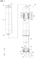
FIG. 1 is a cross-sectional view of a main part of a front fork according to a first embodiment. -
FIG. 2 is an enlarged view illustrating the main part ofFIG. 1 . -
FIG. 3 is an enlarged view illustrating a main part of a front fork according to a second embodiment. -
FIG. 4 is an enlarged view illustrating a main part of a front fork according to a third embodiment. -
FIG. 5 is an enlarged view illustrating a main part of a front fork according to a fourth embodiment. - Embodiments of the present invention will be described below with reference to the accompanying drawings. In the description, left and right refer to left and right based on an occupant on a vehicle, and front and rear refer to front and rear based on a traveling direction of the vehicle. In the figure, Up is shown above and Dn is shown below. The form illustrated in the accompanying drawing is an example of the present invention and the present invention is not limited to the form.
- See
FIG. 1 . Afront fork 10 is an inverted-type hydraulic shock absorber provided in a saddle-ride type vehicle such as a motorcycle or a tricycle and filled with oil inside. - The
front fork 10 includes, anouter tube 11 that has a cylindrical shape and is supported by a vehicle body, aclosing member 12 that closes an upper end of theouter tube 11, a cylinder member 13 (first cylindrical body 13) that has a cylindrical shape, is supported by theclosing member 12, and extends inside theouter tube 11, and abracket 14 that is located at a lower end and supports an axle of a front wheel. Thefront fork 10 further includes an inner tube 15 (second cylindrical body 15), which is a cylindrical body extending upward from thebracket 14 and whosetip 15a exists inside theouter tube 11, and aclosing member 16 which closes a lower end of theinner tube 15 and is fixed inside thebracket 14. Theclosing member 16 is screwed to thebracket 14 by using abolt member 17. Arod 18, which is a cylindrical member supported by thebolt member 17, is provided with a piston (not illustrated) at a tip thereof. Aspring 21 provided between an outer peripheral surface of thecylinder member 13 and an inner peripheral surface of theinner tube 15 applies a force in a direction to separate thecylinder member 13 and theinner tube 15 from each other. Aspring seat portion 30 which receives an upper end (first end) of thespring 21 is provided on an outer peripheral surface of thecylinder member 13, and alower spring seat 23 having a ring shape which receives a lower end (second end) of thespring 21 is supported by theclosing member 16. - The
front fork 10 is compressed so that thebracket 14 and theclosing member 12 come close to each other, for example, when the front wheel rides on a step. When thefront fork 10 is compressed, the oil filled inside is configured to generate a damping force. When thefront fork 10 is compressed to a predetermined position, thefront fork 10 is extended to return to an original position by the force of thespring 21. Even when thefront fork 10 is extended, the oil filled inside is configured to generate a damping force. By generating the damping force, the oil absorbs an impact energy received when riding on a step. Thefront fork 10 will be described in more detail below. - See
FIG. 2 . For example, aluminum or an aluminum alloy is adopted as the material of thecylinder member 13. Thecylinder member 13 includes arecess portion 13a recessed toward an axis CL. Therecess portion 13a is continuously formed in a circumferential direction of thecylinder member 13. An oil chamber filled with oil is provided inside thecylinder member 13. - The
inner tube 15 is located outside thespring 21 and is disposed along an inner peripheral surface of theouter tube 11. Theinner tube 15 is movable in an up-down direction relative to theouter tube 11. - The
closing member 16 receives the lower end of thespring 21 via thelower spring seat 23. Theclosing member 16 has aguide portion 16a which extends upward inside thespring 21 and guides thespring 21. - The tip of the
rod 18 is located inside thecylinder member 13. As a result, the piston provided at the tip of therod 18 can move along the axis CL in the oil chamber located inside thecylinder member 13. - The
spring seat portion 30 includes a fixingportion 31 fixed to the outer peripheral surface of thecylinder member 13, a receivingmember 40 whose upper end is in contact with the fixingportion 31, and aspring seat body 50 that is made of a substantially cylindrical metal and rotatably supported around the axis CL by the receivingmember 40. Thespring seat portion 30 further includes acontact member 34 provided along an outer peripheral surface of thespring seat body 50 and capable of being in contact with the inner peripheral surface of theinner tube 15 and aspring receiving portion 35 which is provided at the lower end of thespring seat body 50 and is in contact with the upper end of thespring 21. - The fixing
portion 31 includes a retainingring 31a which has a ring shape (C shape), is fixed to therecess portion 13a, and has a notch in a part in the circumferential direction and amovement restricting portion 3 1b which is in contact with the retainingring 31a, is restricted from moving upward, and supports the receivingmember 40. - The receiving
member 40 includes asupport portion 41 which is a ring-shaped portion being in contact with themovement restricting portion 3 1b and with which an end of thespring seat body 50 is in contact and a thirdcylindrical body 42 which has a cylindrical shape and extends from thesupport portion 41 along the outer peripheral surface of thecylinder member 13 and with which the inner peripheral surface of thespring seat body 50 can be in contact. - The third
cylindrical body 42 is formed by using a resin having a friction coefficient smaller than that of thespring seat body 50. Examples of such a resin include polytetrafluoroethylene (PTFE) and the like. The support portion 41 (seeFIG. 2 ) is also configured by the same material as the thirdcylindrical body 42. The receivingmember 40 including thesupport portion 41 having a flange shape and the thirdcylindrical body 42 extending along the axis CL in a cylindrical shape can be manufactured, for example, by a known resin molding method. - See
FIG. 2 . The material of thespring seat body 50 is not particularly limited as long as the material is a metal, and for example, aluminum or an aluminum alloy can be used. Thespring seat body 50 includes anend portion 51 that is in contact with the outer peripheral surface of the receivingmember 40 and is rotatably supported around the axis CL by the receivingmember 40, a taperedportion 52 extending diagonally from theend portion 51 toward theinner tube 15, and atip portion 53 extending from a tip of the taperedportion 52 along the inner peripheral surface of theinner tube 15. The taperedportion 52 has a plurality ofholes 52a through which oil can pass. - It is also conceivable that the
spring seat body 50 is configured by resin and also functions as the thirdcylindrical body 42. However, since thespring seat body 50 is a component that receives thespring 21, it is conceivable that a large force is received from thespring 21 in a situation such as immediately after a jumped saddle-ride type vehicle lands. From the viewpoint of making thespring seat body 50 easy to prevent damage even under such circumstances, a metal having a high toughness and a long lifespan is adopted for thespring seat body 50. - The
contact member 34 is a member provided between the outer peripheral surface of thespring seat body 50 and the inner peripheral surface of theinner tube 15. Also, thecontact member 34 is a member for reducing a frictional force when thespring seat body 50 moves along the axis CL or rotates about the axis CL. - The
spring receiving portion 35 covers the lower surface and the outer peripheral surface of thetip portion 53 and is continuously provided in the circumferential direction of thespring seat portion 30. Thespring receiving portion 35 is provided with a gap with respect to thecylinder member 13. By providing thespring receiving portion 35 with a gap with respect to thecylinder member 13, oil can pass through the gap. - The
lower spring seat 23 covers the upper surface and the outer peripheral surface of the closingmember 16 and is continuously provided in the circumferential direction of the closingmember 16. - The
front fork 10 described above is summarized below. - See
FIG. 2 . Thefront fork 10 includes thecylinder member 13 that is the first cylindrical body formed in a cylindrical shape, and theinner tube 15 that is a cylindrical body surrounding the outer peripheral surface of thecylinder member 13 and is the second cylindrical body provided so as to be movable in the direction of the axis CL with respect to thecylinder member 13. Thefront fork 10 further includes thespring 21 that is provided between the outer peripheral surface of thecylinder member 13 and the inner peripheral surface of theinner tube 15 and applies a force in a direction to separate thecylinder member 13 and theinner tube 15 from each other, and thespring seat portion 30 that is provided on the outer peripheral surface of thecylinder member 13 and receives the first end of thespring 21. Thespring seat portion 30 includes the fixingportion 31 fixed to thecylinder member 13, thespring seat body 50 that is made of metal and receives thespring 21, and the thirdcylindrical body 42 that is disposed between the inner peripheral surface of thespring seat body 50 and the outer peripheral surface of thecylinder member 13 and reduces the frictional force when thespring seat body 50 rotates around the axis CL. - The
spring seat portion 30 includes the thirdcylindrical body 42 formed of a material such as a resin having a friction coefficient smaller than that of thespring seat body 50 between the inner peripheral surface of thespring seat body 50 that is made of metal and receives thespring 21 and the outer peripheral surface of thecylinder member 13. While the saddle-ride type vehicle is running, a force in a direction of rotation about the axis CL is applied to thespring 21, so that a force in the direction of rotation is also applied to thespring seat body 50 which receives thespring 21. By providing the thirdcylindrical body 42, the frictional force between thespring seat body 50 and thecylinder member 13 when thespring seat body 50 rotates can be reduced. As a result, the rotation of thespring 21 is less likely to be hindered, so that the operability of the front fork can be improved as compared with the case of the related art. - The
front fork 10 further includes thesupport portion 41 that is provided between the fixingportion 31 and the thirdcylindrical body 42 and rotatably supports the end of thespring seat body 50. By receiving the load in a direction parallel to the axis CL, the force in the rotation direction applied to thespring 21 can be released more easily. - In the
front fork 10, the thirdcylindrical body 42 and thesupport portion 41 are integrally configured by one member. As a result, the number of components can be reduced. -
FIG. 3 illustrates a main part of afront fork 10A according to a second embodiment. In thefront fork 10A according to the second embodiment, unlike the receivingmember 40 used for the front fork 10 (seeFIG. 2 ) according to the first embodiment, a thirdcylindrical body 62 and asupport portion 61 are configured by separate members. Other basic configurations are the same as those of thefront fork 10 according to the first embodiment. For the parts common to those of the first embodiment, the same reference numerals and letters are used and detailed description thereof will be omitted. - The
support portion 61 supports the end of thespring seat body 50 so that thespring seat body 50 can rotate about the axis CL. The thirdcylindrical body 62 is provided between the inner peripheral surface of thespring seat body 50 and the outer peripheral surface of thecylinder member 13 along the inner peripheral surface of thespring seat body 50. The thirdcylindrical body 62 rotatably supports thespring seat body 50 around the axis CL. - The
front fork 10A configured as described above also has the predetermined effects of the present invention. - In the
front fork 10A, the thirdcylindrical body 62 and thesupport portion 61 are configured by separate members. By using the separate members, it becomes easy to select an appropriate material for each of the thirdcylindrical body 62 and thesupport portion 61, and to select the optimum numerical value for the dimensions such as the thickness of each. Further, by configuring the thirdcylindrical body 62 and thesupport portion 61 with separate members, it is also possible to newly design only the thirdcylindrical body 62 and use thesupport portion 61 as the related art. -
FIG. 4 illustrates a main part of afront fork 10B according to a third embodiment. In thefront fork 10B according to the third embodiment, thesupport portion 61 used for thefront fork 10A (seeFIG. 3 ) according to the second embodiment is removed, and the thirdcylindrical body 62 is provided. Other basic configurations are the same as those of thefront forks front forks - The
front fork 10B configured as described above also has the predetermined effects of the present invention. -
FIG. 5 illustrates a main part of afront fork 10C according to a fourth embodiment. In thefront fork 10C according to the fourth embodiment, thelower spring seat 23 used for the front fork 10 (seeFIG. 2 ) according to the first embodiment is removed. Other basic configurations are the same as those of thefront fork 10 according to the first embodiment. For the parts common to those of the first embodiment, the same reference numerals and letters are used and detailed description thereof will be omitted. - The
front fork 10C configured as described above also has the predetermined effects of the present invention. - In the
front fork 10C, the lower end (the other end) of thespring 21 is in contact with the closingmember 16 which closes the end of theinner tube 15. In other words, the lower end of thespring 21 is in contact with the closingmember 16 directly without using the lower spring seat 23 (seeFIG. 2 ). By using the thirdcylindrical body 42, the force applied in the rotation direction of thespring 21 can be smoothly released. Therefore, even when the closingmember 16 having a higher friction coefficient than that of thelower spring seat 23 receives the lower end of thespring 21, the force applied in the rotation direction at the upper end can be sufficiently released. - In the above description, the embodiments in which the third
cylindrical bodies support portions - In addition, each of the above embodiments can be combined as appropriate. For example, it is possible to remove the
lower spring seat 23 from thefront fork 10A illustrated in the second embodiment in which thesupport portion 61 and the thirdcylindrical body 62 are configured by separate members. - That is, the present invention is not limited to the embodiments as long as the operations and effects of the present invention are exhibited.
- The front fork of the present invention is suitable for a saddle-ride type vehicle.
-
- 10, 10A, 10B, 10C: front fork
- 13: cylinder member (first cylindrical body)
- 15: inner tube (second cylindrical body)
- 16: closing member
- 21: spring
- 30: spring seat portion
- 31: fixing portion
- 41, 61: support portion
- 42, 62: third cylindrical body
- 50: spring seat body
- CL: axis
Claims (6)
- A front fork, comprising:a first cylindrical body that is formed in a cylindrical shape;a second cylindrical body that surrounds an outer peripheral surface of the first cylindrical body and is provided so as to be movable in a direction of an axis with respect to the first cylindrical body;a spring that is provided between the outer peripheral surface of the first cylindrical body and an inner peripheral surface of the second cylindrical body and applies a force in a direction to separate the first cylindrical body and the second cylindrical body; anda spring seat portion that is provided on the outer peripheral surface of the first cylindrical body and receives a first end of the spring, whereinthe spring seat portion includes, a fixing portion that is fixed to the first cylindrical body, a spring seat body that is made of metal and receives the spring, and a third cylindrical body that is disposed between an inner peripheral surface of the spring seat body and the outer peripheral surface of the first cylindrical body and reduces a frictional force when the spring seat body rotates about the axis.
- The front fork according to claim 1, further comprising:
a support portion that is provided between the fixing portion and the third cylindrical body and supports the spring seat body. - The front fork according to claim 2, wherein
the third cylindrical body and the support portion are integrally configured by one member. - The front fork according to claim 2, wherein
the third cylindrical body and the support portion are configured by separate members. - The front fork according to any one of claims 2 to 4, wherein
a second end of the spring, which is an end opposite to the first end, is in contact with the closing member which closes an end of the second cylindrical body. - A front fork, comprising:a first cylindrical body that is formed in a cylindrical shape;a second cylindrical body that surrounds an outer peripheral surface of the first cylindrical body and is provided so as to be movable in a direction of an axis with respect to the first cylindrical body;a spring that is provided between the outer peripheral surface of the first cylindrical body and an inner peripheral surface of the second cylindrical body and applies a force in a direction to separate the first cylindrical body and the second cylindrical body; anda spring seat portion that is provided on the outer peripheral surface of the first cylindrical body and receives a first end of the spring, whereinthe spring seat portion includes, a fixing portion that is fixed to the first cylindrical body, a spring seat body that is made of metal and receives the spring, a third cylindrical body that is disposed between an inner peripheral surface of the spring seat body and the outer peripheral surface of the first cylindrical body and reduces a frictional force when the spring seat body rotates about the axis, and a support portion that is provided between the fixing portion and the third cylindrical body and supports the spring seat body, wherein
the third cylindrical body and the support portion are integrally configured by one member.
Applications Claiming Priority (1)
| Application Number | Priority Date | Filing Date | Title |
|---|---|---|---|
| PCT/JP2020/022374 WO2021245929A1 (en) | 2020-06-05 | 2020-06-05 | Front fork |
Publications (3)
| Publication Number | Publication Date |
|---|---|
| EP4163196A1 true EP4163196A1 (en) | 2023-04-12 |
| EP4163196A4 EP4163196A4 (en) | 2024-03-13 |
| EP4163196B1 EP4163196B1 (en) | 2026-06-17 |
Family
ID=73219977
Family Applications (1)
| Application Number | Title | Priority Date | Filing Date |
|---|---|---|---|
| EP20938758.8A Active EP4163196B1 (en) | 2020-06-05 | 2020-06-05 | Front fork |
Country Status (4)
| Country | Link |
|---|---|
| US (1) | US12466510B2 (en) |
| EP (1) | EP4163196B1 (en) |
| JP (1) | JP6785398B1 (en) |
| WO (1) | WO2021245929A1 (en) |
Families Citing this family (1)
| Publication number | Priority date | Publication date | Assignee | Title |
|---|---|---|---|---|
| DE112019006745T5 (en) * | 2019-04-03 | 2022-01-13 | Hitachi Astemo, Ltd. | shock absorber |
Family Cites Families (15)
| Publication number | Priority date | Publication date | Assignee | Title |
|---|---|---|---|---|
| US4278266A (en) * | 1979-07-20 | 1981-07-14 | Honda Giken Kogyo Kabushiki Kaisha | Front fork construction for motorcycle |
| JPS6025308B2 (en) * | 1980-09-16 | 1985-06-17 | 株式会社昭和製作所 | Front forks of motorcycles, etc. |
| US4881750A (en) * | 1989-02-06 | 1989-11-21 | Hartmann Dirck T | ATB shock absorber |
| US7290643B2 (en) * | 2003-12-17 | 2007-11-06 | Nobuaki Fujita | Front fork in two-wheeled motor vehicle or the like |
| JP5008548B2 (en) * | 2007-12-27 | 2012-08-22 | 株式会社ショーワ | Hydraulic shock absorber |
| EP2233775B1 (en) * | 2009-03-23 | 2012-02-08 | BWI Company Limited S.A. | Hydraulic suspension damper |
| JP2014240664A (en) * | 2011-10-04 | 2014-12-25 | ヤマハ発動機株式会社 | Vehicle shock absorber |
| JP5847612B2 (en) * | 2012-02-29 | 2016-01-27 | 株式会社ショーワ | Spring leg for front fork |
| JP2014118132A (en) * | 2012-12-12 | 2014-06-30 | Yusuke Mashita | Front fork friction reduction mechanism |
| JP6653613B2 (en) * | 2016-03-31 | 2020-02-26 | 株式会社ショーワ | Suspensions and suspension systems |
| US9821877B2 (en) * | 2016-04-26 | 2017-11-21 | Chin-Sung Tsai | Pressure-balanced shock absorber for a bicycle |
| JP6174206B1 (en) * | 2016-07-29 | 2017-08-02 | 株式会社ショーワ | Front fork |
| JP6405076B1 (en) * | 2018-07-09 | 2018-10-17 | 株式会社ショーワ | Shock absorber |
| WO2020129169A1 (en) * | 2018-12-19 | 2020-06-25 | 株式会社ショーワ | Front fork |
| WO2022079880A1 (en) * | 2020-10-16 | 2022-04-21 | 日立Astemo株式会社 | Damper and method for manufacturing said damper |
-
2020
- 2020-06-05 JP JP2020531185A patent/JP6785398B1/en active Active
- 2020-06-05 WO PCT/JP2020/022374 patent/WO2021245929A1/en not_active Ceased
- 2020-06-05 EP EP20938758.8A patent/EP4163196B1/en active Active
-
2022
- 2022-03-14 US US17/694,066 patent/US12466510B2/en active Active
Also Published As
| Publication number | Publication date |
|---|---|
| EP4163196A4 (en) | 2024-03-13 |
| WO2021245929A1 (en) | 2021-12-09 |
| US12466510B2 (en) | 2025-11-11 |
| EP4163196B1 (en) | 2026-06-17 |
| JPWO2021245929A1 (en) | 2021-12-09 |
| US20220204117A1 (en) | 2022-06-30 |
| JP6785398B1 (en) | 2020-11-18 |
Similar Documents
| Publication | Publication Date | Title |
|---|---|---|
| US8434772B2 (en) | Damper tube reinforcement sleeve | |
| KR102477361B1 (en) | Slide bearing and strut-type suspension | |
| US8496094B2 (en) | Spring suspension for a handlebar-steered vehicle | |
| EP2738076B1 (en) | Suspension device | |
| EP3290726B1 (en) | Sliding bearing | |
| EP3677809B1 (en) | Hydraulic damper | |
| US12466510B2 (en) | Front fork | |
| JP6550197B1 (en) | Front fork | |
| US8992094B2 (en) | Suspension strut bearing | |
| EP2740964A2 (en) | Air shock absorber and straddle-type vehicle | |
| EP3217036B1 (en) | Suspension device | |
| JP6343213B2 (en) | Front fork | |
| KR101337585B1 (en) | Shock Absorber | |
| JP7113143B2 (en) | Cylinder device | |
| JP6637806B2 (en) | Suspension system | |
| US20150197132A1 (en) | Shock absorber | |
| JP2015108404A (en) | Pressure shock absorber | |
| JP4575125B2 (en) | Guide bush structure of hydraulic shock absorber | |
| JPWO2020202520A1 (en) | Buffer | |
| JP2007092926A (en) | shock absorber | |
| JP2012180890A (en) | Front fork | |
| JP2019018628A (en) | Spring seat and bearing device | |
| WO2026100069A1 (en) | Shock absorber | |
| JP2025018020A (en) | Front fork | |
| JP6503871B2 (en) | Suspension mounting device |
Legal Events
| Date | Code | Title | Description |
|---|---|---|---|
| STAA | Information on the status of an ep patent application or granted ep patent |
Free format text: STATUS: THE INTERNATIONAL PUBLICATION HAS BEEN MADE |
|
| PUAI | Public reference made under article 153(3) epc to a published international application that has entered the european phase |
Free format text: ORIGINAL CODE: 0009012 |
|
| STAA | Information on the status of an ep patent application or granted ep patent |
Free format text: STATUS: REQUEST FOR EXAMINATION WAS MADE |
|
| 17P | Request for examination filed |
Effective date: 20220311 |
|
| AK | Designated contracting states |
Kind code of ref document: A1 Designated state(s): AL AT BE BG CH CY CZ DE DK EE ES FI FR GB GR HR HU IE IS IT LI LT LU LV MC MK MT NL NO PL PT RO RS SE SI SK SM TR |
|
| DAV | Request for validation of the european patent (deleted) | ||
| DAX | Request for extension of the european patent (deleted) | ||
| A4 | Supplementary search report drawn up and despatched |
Effective date: 20240213 |
|
| RIC1 | Information provided on ipc code assigned before grant |
Ipc: B62K 25/08 20060101AFI20240207BHEP |
|
| RAP3 | Party data changed (applicant data changed or rights of an application transferred) |
Owner name: ASTEMO, LTD. |
|
| GRAP | Despatch of communication of intention to grant a patent |
Free format text: ORIGINAL CODE: EPIDOSNIGR1 |
|
| STAA | Information on the status of an ep patent application or granted ep patent |
Free format text: STATUS: GRANT OF PATENT IS INTENDED |
|
| INTG | Intention to grant announced |
Effective date: 20260121 |
|
| GRAS | Grant fee paid |
Free format text: ORIGINAL CODE: EPIDOSNIGR3 |
|
| GRAA | (expected) grant |
Free format text: ORIGINAL CODE: 0009210 |
|
| STAA | Information on the status of an ep patent application or granted ep patent |
Free format text: STATUS: THE PATENT HAS BEEN GRANTED |
|
| AK | Designated contracting states |
Kind code of ref document: B1 Designated state(s): AL AT BE BG CH CY CZ DE DK EE ES FI FR GB GR HR HU IE IS IT LI LT LU LV MC MK MT NL NO PL PT RO RS SE SI SK SM TR |
|
| REG | Reference to a national code |
Ref country code: CH Ref legal event code: F10 Free format text: ST27 STATUS EVENT CODE: U-0-0-F10-F00 (AS PROVIDED BY THE NATIONAL OFFICE) Effective date: 20260617 Ref country code: GB Ref legal event code: FG4D |
|
| REG | Reference to a national code |
Ref country code: DE Ref legal event code: R096 Ref document number: 602020073489 Country of ref document: DE |
|
| REG | Reference to a national code |
Ref country code: IE Ref legal event code: FG4D |