EP4163163A1 - Energy storage system and cooling arrangment for a vehicle and methods - Google Patents
Energy storage system and cooling arrangment for a vehicle and methods Download PDFInfo
- Publication number
- EP4163163A1 EP4163163A1 EP21200843.7A EP21200843A EP4163163A1 EP 4163163 A1 EP4163163 A1 EP 4163163A1 EP 21200843 A EP21200843 A EP 21200843A EP 4163163 A1 EP4163163 A1 EP 4163163A1
- Authority
- EP
- European Patent Office
- Prior art keywords
- volume
- heat transfer
- cooling
- energy storage
- arrangement
- Prior art date
- Legal status (The legal status is an assumption and is not a legal conclusion. Google has not performed a legal analysis and makes no representation as to the accuracy of the status listed.)
- Granted
Links
Images

Classifications
-
- F—MECHANICAL ENGINEERING; LIGHTING; HEATING; WEAPONS; BLASTING
- F28—HEAT EXCHANGE IN GENERAL
- F28D—HEAT-EXCHANGE APPARATUS, NOT PROVIDED FOR IN ANOTHER SUBCLASS, IN WHICH THE HEAT-EXCHANGE MEDIA DO NOT COME INTO DIRECT CONTACT
- F28D20/00—Heat storage plants or apparatus in general; Regenerative heat-exchange apparatus not covered by groups F28D17/00 or F28D19/00
- F28D20/0034—Heat storage plants or apparatus in general; Regenerative heat-exchange apparatus not covered by groups F28D17/00 or F28D19/00 using liquid heat storage material
-
- B—PERFORMING OPERATIONS; TRANSPORTING
- B60—VEHICLES IN GENERAL
- B60T—VEHICLE BRAKE CONTROL SYSTEMS OR PARTS THEREOF; BRAKE CONTROL SYSTEMS OR PARTS THEREOF, IN GENERAL; ARRANGEMENT OF BRAKING ELEMENTS ON VEHICLES IN GENERAL; PORTABLE DEVICES FOR PREVENTING UNWANTED MOVEMENT OF VEHICLES; VEHICLE MODIFICATIONS TO FACILITATE COOLING OF BRAKES
- B60T1/00—Arrangements of braking elements, i.e. of those parts where braking effect occurs specially for vehicles
- B60T1/02—Arrangements of braking elements, i.e. of those parts where braking effect occurs specially for vehicles acting by retarding wheels
- B60T1/10—Arrangements of braking elements, i.e. of those parts where braking effect occurs specially for vehicles acting by retarding wheels by utilising wheel movement for accumulating energy, e.g. driving air compressors
-
- B—PERFORMING OPERATIONS; TRANSPORTING
- B60—VEHICLES IN GENERAL
- B60L—PROPULSION OF ELECTRICALLY-PROPELLED VEHICLES; SUPPLYING ELECTRIC POWER FOR AUXILIARY EQUIPMENT OF ELECTRICALLY-PROPELLED VEHICLES; ELECTRODYNAMIC BRAKE SYSTEMS FOR VEHICLES IN GENERAL; MAGNETIC SUSPENSION OR LEVITATION FOR VEHICLES; MONITORING OPERATING VARIABLES OF ELECTRICALLY-PROPELLED VEHICLES; ELECTRIC SAFETY DEVICES FOR ELECTRICALLY-PROPELLED VEHICLES
- B60L58/00—Methods or circuit arrangements for monitoring or controlling batteries or fuel cells, specially adapted for electric vehicles
- B60L58/10—Methods or circuit arrangements for monitoring or controlling batteries or fuel cells, specially adapted for electric vehicles for monitoring or controlling batteries
- B60L58/24—Methods or circuit arrangements for monitoring or controlling batteries or fuel cells, specially adapted for electric vehicles for monitoring or controlling batteries for controlling the temperature of batteries
- B60L58/26—Methods or circuit arrangements for monitoring or controlling batteries or fuel cells, specially adapted for electric vehicles for monitoring or controlling batteries for controlling the temperature of batteries by cooling
-
- B—PERFORMING OPERATIONS; TRANSPORTING
- B60—VEHICLES IN GENERAL
- B60L—PROPULSION OF ELECTRICALLY-PROPELLED VEHICLES; SUPPLYING ELECTRIC POWER FOR AUXILIARY EQUIPMENT OF ELECTRICALLY-PROPELLED VEHICLES; ELECTRODYNAMIC BRAKE SYSTEMS FOR VEHICLES IN GENERAL; MAGNETIC SUSPENSION OR LEVITATION FOR VEHICLES; MONITORING OPERATING VARIABLES OF ELECTRICALLY-PROPELLED VEHICLES; ELECTRIC SAFETY DEVICES FOR ELECTRICALLY-PROPELLED VEHICLES
- B60L58/00—Methods or circuit arrangements for monitoring or controlling batteries or fuel cells, specially adapted for electric vehicles
- B60L58/30—Methods or circuit arrangements for monitoring or controlling batteries or fuel cells, specially adapted for electric vehicles for monitoring or controlling fuel cells
- B60L58/32—Methods or circuit arrangements for monitoring or controlling batteries or fuel cells, specially adapted for electric vehicles for monitoring or controlling fuel cells for controlling the temperature of fuel cells, e.g. by controlling the electric load
- B60L58/33—Methods or circuit arrangements for monitoring or controlling batteries or fuel cells, specially adapted for electric vehicles for monitoring or controlling fuel cells for controlling the temperature of fuel cells, e.g. by controlling the electric load by cooling
-
- F—MECHANICAL ENGINEERING; LIGHTING; HEATING; WEAPONS; BLASTING
- F16—ENGINEERING ELEMENTS AND UNITS; GENERAL MEASURES FOR PRODUCING AND MAINTAINING EFFECTIVE FUNCTIONING OF MACHINES OR INSTALLATIONS; THERMAL INSULATION IN GENERAL
- F16D—COUPLINGS FOR TRANSMITTING ROTATION; CLUTCHES; BRAKES
- F16D61/00—Brakes with means for making the energy absorbed available for use
-
- B—PERFORMING OPERATIONS; TRANSPORTING
- B60—VEHICLES IN GENERAL
- B60H—ARRANGEMENTS OF HEATING, COOLING, VENTILATING OR OTHER AIR-TREATING DEVICES SPECIALLY ADAPTED FOR PASSENGER OR GOODS SPACES OF VEHICLES
- B60H1/00—Heating, cooling or ventilating devices
- B60H1/00271—HVAC devices specially adapted for particular vehicle parts or components and being connected to the vehicle HVAC unit
- B60H1/00278—HVAC devices specially adapted for particular vehicle parts or components and being connected to the vehicle HVAC unit for the battery
-
- B—PERFORMING OPERATIONS; TRANSPORTING
- B60—VEHICLES IN GENERAL
- B60K—ARRANGEMENT OR MOUNTING OF PROPULSION UNITS OR OF TRANSMISSIONS IN VEHICLES; ARRANGEMENT OR MOUNTING OF PLURAL DIVERSE PRIME-MOVERS IN VEHICLES; AUXILIARY DRIVES FOR VEHICLES; INSTRUMENTATION OR DASHBOARDS FOR VEHICLES; ARRANGEMENTS IN CONNECTION WITH COOLING, AIR INTAKE, GAS EXHAUST OR FUEL SUPPLY OF PROPULSION UNITS IN VEHICLES
- B60K6/00—Arrangement or mounting of plural diverse prime-movers for mutual or common propulsion, e.g. hybrid propulsion systems comprising electric motors and internal combustion engines
- B60K6/08—Prime-movers comprising combustion engines and mechanical or fluid energy storing means
-
- B—PERFORMING OPERATIONS; TRANSPORTING
- B60—VEHICLES IN GENERAL
- B60T—VEHICLE BRAKE CONTROL SYSTEMS OR PARTS THEREOF; BRAKE CONTROL SYSTEMS OR PARTS THEREOF, IN GENERAL; ARRANGEMENT OF BRAKING ELEMENTS ON VEHICLES IN GENERAL; PORTABLE DEVICES FOR PREVENTING UNWANTED MOVEMENT OF VEHICLES; VEHICLE MODIFICATIONS TO FACILITATE COOLING OF BRAKES
- B60T2270/00—Further aspects of brake control systems not otherwise provided for
- B60T2270/60—Regenerative braking
-
- Y—GENERAL TAGGING OF NEW TECHNOLOGICAL DEVELOPMENTS; GENERAL TAGGING OF CROSS-SECTIONAL TECHNOLOGIES SPANNING OVER SEVERAL SECTIONS OF THE IPC; TECHNICAL SUBJECTS COVERED BY FORMER USPC CROSS-REFERENCE ART COLLECTIONS [XRACs] AND DIGESTS
- Y02—TECHNOLOGIES OR APPLICATIONS FOR MITIGATION OR ADAPTATION AGAINST CLIMATE CHANGE
- Y02E—REDUCTION OF GREENHOUSE GAS [GHG] EMISSIONS, RELATED TO ENERGY GENERATION, TRANSMISSION OR DISTRIBUTION
- Y02E60/00—Enabling technologies; Technologies with a potential or indirect contribution to GHG emissions mitigation
- Y02E60/10—Energy storage using batteries
Definitions
- the present disclosure relates an energy storage system for a vehicle, to a cooling arrangement for a vehicle comprising an energy storage system, and to a method for energy storage of recuperation energy from an energy recuperating arrangement in a vehicle, such as from a braking arrangement in a vehicle.
- a need for recuperating energy from various devices or arrangements in the vehicle may arise.
- One example is braking energy released during regenerative braking of the vehicle.
- recuperating energy arises in vehicles with combustion engines as well as in wholly or partly electric vehicles, comprising an electric machine and/or an electric supply system for propulsion of the vehicle or for assisting the propulsion of the vehicle.
- vehicles having a battery it is possible to recuperate energy e.g. by storage of energy in the battery
- An object of the invention is to provide an alternative and/or an improvement relating to one or more of the needs as set out in the above.
- an energy storage system for a vehicle comprising an energy storage tank defining a tank volume for a heat transfer fluid, and comprising a partition dividing the tank volume into a first volume and a second volume, wherein the partition is movable to/from any position between a minimum energy storage position corresponding to a minimum second volume, and a maximum energy storage position corresponding to a maximum second volume, the energy storage tank further comprising a biasing device being arranged such that movement of the partition away from the minimum energy storage position corresponds to storing energy in the biasing device, and movement towards the minimum energy storage position corresponds to releasing energy from the biasing device; the energy storage system further comprising
- the proposed energy storage system provides for storage of energy in two forms using the energy storage tank.
- thermal energy may be stored by means of the heat transfer arrangement heating/cooling the heat transfer fluid stored in the second volume.
- mechanical energy may be stored by means of the biasing device storing energy when moved towards the maximum energy storage position as heat transfer fluid flows into the second volume.
- recuperated energy may be used for driving the heat transfer arrangement and/or the fluid control assembly, resulting in the recuperated energy being stored in the energy storage tank in the form of thermal energy and energy stored by the biasing device.
- the heat transfer arrangement is arranged along the heat transfer fluid duct.
- efficient altering of the temperature of the heat transfer fluid may take place along the passage of the heat transfer fluid flow from the first volume to the second volume.
- the fluid control assembly and/or heat transfer arrangement are configured to be driven by recuperated energy from an energy recuperating arrangement.
- the energy recuperating arrangement is a braking arrangement.
- the energy storage system may be used for recuperating the braking energy from a braking arrangement in a vehicle, such as in a vehicle comprising an electric machine and/or an electric supply system for propulsion of the vehicle or for assisting the propulsion of the vehicle..
- the one or more heat transfer arrangement is a cooling arrangement for cooling the heat transfer fluid.
- the heat transfer fluid in the second volume has a lower temperature than the heat transfer fluid in the first volume.
- the maximum energy storage position corresponding to a maximum second volume corresponds to a maximum cool storage position. This enables use of the stored thermal energy for cooling, such as in a cooling arrangement, for example a cooling arrangement in a vehicle.
- the one or more heat transfer element may be a heating element for heating the heat transfer fluid. This implies that the heat transfer fluid in the second volume has a higher temperature than the heat transfer fluid in the first volume, and that the maximum energy storage position corresponds to a maximum heat storage position. In this case, the stored thermal energy may instead be used for heating.
- the heat transfer arrangement comprises one or more cooling elements.
- At least one of the one or more cooling elements is a compressor for cooling the heat transfer fluid.
- the compressor may be driven by recuperated energy.
- the fluid control assembly is arranged for providing a pressure implying a flow of heat transfer fluid from the first volume to the second volume via the one or more heat transfer elements.
- the fluid control assembly may be any device suitable for providing a pressure implying such a flow. The pressure thus needs to overcome a counter-pressure provided by the biasing device of the energy storage tank, so as to enable flow of heat transfer fluid from the first volume to the second volume while moving the partition towards the maximum energy storage position and storing energy in the biasing device.
- the fluid control assembly may be wholly or partly driven by recuperated energy.
- the fluid control assembly may comprise a pump.
- the pump may be driven by recuperated energy.
- the fluid control assembly may comprise an actuator.
- an actuator may be arranged to act on the partition and/or the biasing device so as act in a direction for moving the partition towards the maximum energy storage position and storing energy in the biasing device.
- the energy storage system comprises a control unit adapted to control the fluid control assembly and/or heat transfer arrangement.
- a cooling arrangement comprising an energy storage system according to any one of the preceding claims, the cooling arrangement further comprising a cooling system for cooling one or more devices using the heat transfer fluid, and a valve arrangement for controlling a flow of heat transfer fluid from the second volume to the first volume via the cooling system.
- the cooling system comprises a cooling system fluid duct connecting the second volume and the first volume, wherein the one or more devices is/are arranged along the cooling system fluid duct.
- the cooling system fluid duct may be at least partly separate from the heat transfer fluid duct of the energy storage system.
- at least partly separate means that the cooling system fluid duct comprises at least a portion which is not also a part of the heat transfer fluid duct.
- the energy storage tank may for example be provided with a first volume inlet/outlet and a second volume inlet/outlet, wherein the inlet/outlets allow flow in different directions when used to provide the heat transfer fluid duct or the cooling system fluid duct, respectively.
- the cooling system fluid duct may be completely separate from the heat transfer fluid duct of the energy storage system.
- completely separate is meant that the cooling system fluid duct comprises no portion which is also a part of the heat transfer fluid duct.
- the energy storage tank may for example be provided with a first volume outlet and a second volume inlet connected to the heat transfer fluid duct, and with a first volume inlet and a second volume outlet connected to the cooling system fluid duct.
- one of the one or more devices is an electrical energy supply system, such as a fuel cell system.
- the cooling system may be a cooling system for cooling at least one fuel cell system using the heat transfer fluid.
- the cooling system may comprise a control unit adapted to control the valve arrangement.
- the energy storage system may comprise a control unit, and this control unit may be arranged so as to control also the valve arrangement of the cooling system.
- the object is achieved by a method for energy storage of recuperation energy according to claim 13.
- a method for energy storage of recuperation energy from an energy recuperating arrangement, in an energy storage system according to the first aspect and/or a cooling arrangement according to the second aspect. The method comprises:
- a fourth aspect there is provided a method for cooling one or more devices in a cooling arrangement according to the second aspect, the method comprising:
- the object is achieved by a method for controlling a cooling arrangement according to the second aspect, according to claim 15.
- a method for controlling a cooling arrangement according to the second aspect comprising
- the method may involve selectively running one of the energy recuperation mode and the cooling mode.
- the method may comprise using information indicative of the availability of recuperation energy as input for determining when to operate the cooling arrangement in the energy recuperation mode.
- the method may comprise using information indicative of the need for cooling the one or more devices as input for determining when to operate the cooling arrangement in the cooling mode.
- the method may comprise operating the cooling arrangement in the energy recuperation mode while the partition is in other than the maximum energy storage position.
- the method may comprise operating the cooling arrangement in the cooling mode while the partition is in other than the minimum energy storage position.
- the method may comprise using information regarding the position of the partition in the energy storage tank as input.
- control unit configured for performing any one of the methods described herein.
- the object is achieved by a vehicle comprising an energy storage system according to the first aspect and/or a cooling arrangement according to the second aspect, wherein preferably the fluid control assembly and/or cooling arrangement are configured to be driven by recuperated energy from a braking arrangement of the vehicle.
- the vehicle comprises and/or is arranged to communicate with a control unit according to the sixth aspect.
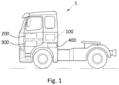
- Fig. 1 illustrates a variant of a vehicle 1 as disclosed herein for which the invention as disclosed herein may be implemented.
- the invention can be applied in any vehicle, such as in a boat or car.
- the invention can be applied in heavy-duty vehicles, such as trucks, buses and construction equipment.
- trucks, buses and construction equipment such as trucks, buses and construction equipment.
- the invention will be described herein with respect to a truck, the invention is not restricted to this particular vehicle, but may also be used in other vehicles such as working machines or buses.
- the need for recuperating energy from various systems and/or devices in the vehicle 1 may occur.
- the vehicle 1 may comprise a braking system 400 which, when in use for braking, will absorb energy which may need to be either recuperated or dissipated.
- the vehicle 1 may comprise a propulsion system comprising a combustion engine and/or an electrical energy supply system such as a battery and/or a fuel cell system.
- the propulsion system comprises a fuel cell system 300.
- the vehicle 1 may comprise a cooling system 200 using a heat transfer fluid to cool one or more devices in the vehicle 1.
- the vehicle 1 comprises an energy storage system 100 as will be described in the below.
- the energy storage system 100 may be used in a cooling arrangement together with the cooling system 200, for recuperating energy from a system in the vehicle 1 such as the braking system 400.
- the cooling system 200 may be arranged for cooling the fuel cell system 300, as will also be described in the below.
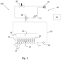
- Fig. 2 illustrates schematically an example of an energy storage system 100 according to the first aspect, which may be used for recuperating energy from a system such as a braking system 400 in a vehicle 1.
- the energy storage system 100 comprises an energy storage tank 10 defining a tank volume for a heat transfer fluid.
- the energy storage tank 10 comprises a partition 12 dividing the tank volume into a first volume V1 and a second volume V2.
- the partition 12 is movable to/from any position between a minimum energy storage position corresponding to a minimum second volume V2, and a maximum energy storage position corresponding to a maximum second volume V2.
- the tank 10 as such, and the first and second volumes V1, V2 are suitably isolated so as to enable the heat transfer fluid in said first and second volumes V1, V2, respectively, to be maintained at a relatively constant temperature over substantial periods of time.
- the energy storage tank 10 further comprises a biasing device 18 being arranged such that movement of the partition 12 away from the minimum energy storage position corresponds to storing energy in the biasing device 18, and movement towards the minimum energy storage position corresponds to releasing energy from the biasing device 18.
- the biasing device 18 may comprise one or more spring element(s) arranged so as to bias the partition 12 towards the minimum energy storage position.
- the spring element(s) are arranged such that movement of the partition 12 away from the minimum energy storage position corresponds to storing energy in the biasing device 18, and movement towards the minimum energy storage position corresponds to releasing energy from the biasing device 18, as outlined in the above.
- the spring element(s) may for example be one or more compression springs or tension springs.
- the energy storage system 100 further comprises a heat transfer fluid duct 20 connecting the first volume V1 and the second volume V2.
- the heat transfer fluid duct 20 may be communicating with the first volume V1 via a first volume inlet/outlet 14 and with the second volume V2 via a second volume inlet/outlet 16.
- the energy storage system 100 comprises a fluid control assembly 30 for providing a pressure implying a flow of heat transfer fluid from the first volume V1 to the second volume V2 though the heat transfer fluid duct 20.
- the pressure provided by the fluid control assembly 30 will work against the bias of the biasing device 18 so as to move the partition 12 towards the maximum energy storage position while storing energy in the biasing device 18. Accordingly, the fluid control assembly 30 provides for the storage of energy in mechanical form in the biasing device 18.
- the fluid control assembly 30 may be arranged to be driven by recuperated energy from an energy recuperation arrangement.
- the fluid control assembly 30 may be driven by energy recuperated from a braking arrangement such as the braking arrangement 400 in the vehicle 1 of Fig. 1 .
- the fluid control assembly 30 may for example, and as in the variant of Fig. 2 , be a pump.
- the pump may be adapted to provide a pressure of the heat transfer fluid being sufficient to accomplish the movement of the partition 12 towards the maximum energy storage position while storing energy in the biasing device 18.
- the energy storage system 100 comprises a heat transfer arrangement 40 arranged for altering the temperature of the heat transfer fluid from a first temperature when in the first volume V1 to a second temperature when in the second volume V2.
- the flow of heat transfer fluid from the first volume V1 to the second volume V2 resulting by the action of the fluid control assembly 30 will flow through the heat transfer fluid duct 20 via the heat transfer arrangement 40, thus allowing for the storage of energy in the form of thermal energy in the heat transfer fluid.
- the heat transfer arrangement 40 may be arranged to be driven by recuperated energy from an energy recuperating arrangement.
- the heat transfer arrangement 40 may be driven by energy recuperated from a braking arrangement such as the braking arrangement 400 in the vehicle 1 of Fig. 1 .
- the thermal energy may be used by exploiting a temperature difference between the heat transfer fluid of the second volume V2 and another device, e.g. a device to be cooled/heated by the heat transfer fluid from the second volume V2.
- storage of thermal energy may be made by heating the heat transfer fluid, i.e. by altering the temperature from a first temperature when in the first volume V1 to a second temperature when in the second volume V2, and where the second temperature is higher than the first temperature.
- the storage of thermal energy may be made by cooling the heat transfer fluid, i.e. where the second temperature is lower than the first temperature.
- the alternative to cool the heat transfer fluid may be particularly useful when combined with a cooling system for use in a vehicle.
- the heat transfer arrangement 40 may be arranged anywhere allowing for altering of the temperature of the heat transfer fluid in or flowing to the second volume V2, in relation to the temperature of the heat transfer fluid in the first volume V1.
- the heat transfer arrangement is arranged along the heat transfer fluid duct 20.
- the heat transfer arrangement may be arranged to alter the temperature of the heat transfer fluid when flowing through the heat transfer fluid duct towards the second volume V2. This arrangement allows for various options when it comes to realising the heat transfer arrangement 40.
- the heat transfer arrangement 40 is an arrangement for cooling the heat transfer fluid may be suitable for applications in which it is desired to use the cooled heat transfer fluid from the second volume V2 of the energy storage fuel tank 10 i.e. for a cooling arrangement, as will be described in the below with reference to Fig. 3 .
- the storage system 100 enables storing recuperated energy from an energy recuperating arrangement, such as from a braking arrangement 400, and using the stored energy for cooling purposes such as in a cooling system 200 for cooling one or more devices, for example for cooling a fuel cell system 300.
- the heat transfer arrangement 40 could in other applications be an arrangement for heating the heat transfer fluid, in which case the heat transfer fluid in the second volume V2 has a higher temperature than the heat transfer fluid in the first volume V1 (i.e. the second temperature is higher than the first temperature).
- the maximum energy storage position corresponding to a maximum second volume V2 corresponds to a maximum hot storage position.
- the heated heat transfer fluid from the second volume V2 of the energy storage fuel tank may be used i.e. for a heating arrangement.
- the heat transfer arrangement 40 may, as exemplified in Fig. 2 , comprise a heat transfer circuit arranged for altering the temperature of the heat transfer fluid in the heat transfer fluid duct 20 between the first volume V1 and the second volume V2.
- the heat transfer circuit may comprise one or more heat transfer elements.
- the heat transfer arrangement 40 may comprise a heat transfer circuit 40 for cooling the heat transfer fluid comprising one or more heat transfer elements such as an evaporator 44 and/or a compressor 42.
- the heat transfer arrangement 40 may, as illustrated in Fig. 2 , comprise an evaporator 44, a compressor 42, a condenser 46 and an expansion valve 48.
- One or more of the devices of the heat transfer arrangement 40 may be driven by recuperated energy, for example the compressor 42 in the exemplified heat transfer arrangement 40 may be driven by recuperated energy.
- the energy storage system 100 may further comprise a control unit 60 adapted to control the fluid control assembly 30 and/or heat transfer arrangement 40.
- a control unit 60 may be arranged to communicate with the fluid control assembly 30 and/or heat transfer arrangement 40 via wired or wireless transmission.
- the control unit 60 may be arranged in the vehicle 1 or remote from the vehicle 1.
- control unit 60 may be adapted to control the fluid control assembly 30 and/or heat transfer arrangement 40 to operate when energy from the braking system 400 is available, and/or not to operate when no energy from the braking system is available.
- a method for energy storage of recuperation energy from an energy recuperating arrangement such as an energy recuperating arrangement in a vehicle, in an energy storage system 100, the method comprising: using the recuperation energy for driving the fluid flow control assembly to provide a heat transfer fluid flow from the first volume V1 to the second volume V2 and/or using the recuperation energy for driving the heat transfer element 40 to alter the temperature of the heat transfer fluid.
- the energy storage system 100 may be connected e.g. to a cooling arrangement or to a heating arrangement arranged to use the thermal energy stored in the heat transfer fluid in the second volume V2.
- Fig. 3 illustrates a variant of a cooling arrangement 1000 comprising an energy storage system 100 as described in relation to Fig. 2 , and a cooling system 200 for cooling one or more devices 300 using the heat transfer fluid, and a valve arrangement 52, 54 for controlling a flow of heat transfer fluid from the second volume V2 to the first volume V1 via the cooling system 200.
- FIG. 3 illustrates an example of a cooling arrangement 1000 according to the second aspect.
- a cooling system 200 is arranged to use cooled heat transfer fluid stored in the second volume V2 of the storage tank 10 to cool one or more devices 300.
- the valve arrangement 52, 54 is arranged for controlling a flow of heat transfer fluid from the second volume V2 to the first volume V1, implying that the partition 12 moves in a direction away from the maximum energy storage position, releasing mechanical energy stored in the biasing means 18.
- the valve arrangement 52, 54 may comprise a first valve 52 controlling the outlet of heat transfer fluid from the cooling system 200 to the energy storage system 100, and a second valve 54 controlling the inlet of heat transfer fluid to the cooling system 200 from the energy storage system 100.
- the first valve 52 is arranged to control the outlet of heat transfer fluid from the cooling system 200 to the first volume V1 of the storage tank 10
- the second valve 54 is arranged to control the inlet of heat transfer fluid to the cooling system 200 to the cooling system 200 from the second volume V2 of the storage tank 10.
- valves of the valve arrangement may be any valves as known in the art, for example, and as in the illustrated variant, the first valve 52 may be a three-way valve, and the second valve 54 may be a flow restrictor valve.
- the cooling arrangement may further comprise a control unit 60, arranged to control the valve arrangement 52, 54 so as to control a flow of heat transfer fluid between the energy storage system 100 and the cooling system 200 for cooling the one or more devices 300.
- the control unit 60 for controlling the valve arrangement 52, 54 is also the control unit 60 for controlling the energy storage system 100.
- the one or more devices 300 to be cooled may be any devices in a vehicle 1 which may require cooling.
- At least one device 300 to be cooled may be an electric energy supply system such as a battery system and fuel cell system.
- recuperated energy such as recuperated braking energy which can be recuperated when braking the vehicle, for cooling an electric energy supply system in the vehicle.
- the cooling system provides an efficient solution alleviating two needs associated with vehicles comprising an electric energy supply system such as a fuel cell system, i.e. the need for recuperating energy and the need for cooling the electric energy supply system.
- the cooling arrangement 200 may further comprise additional devices as essentially known in the art.
- a heat transfer fluid cooling element may be arranged downstream the one or more devices 300 to be cooled.
- a heat exchanger 210 such as a heat exchanger 210 arranged at the front of a truck, may be present downstream the one or more devices 300 to be cooled.
- the heat transfer fluid which when used for cooling the one or more devices 300 will itself be heated, may thereafter be cooled by the heat exchanger 210.
- a pump 220 may be arranged to assist the transfer fluid flow in the cooling arrangement 200.
- the cooling system 1000 may operate in two different modes: an energy recuperation mode and a cooling mode.
- the energy recuperation mode is a method for energy storage of recuperation energy from an energy recuperating arrangement in a vehicle, comprising:
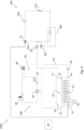
- Fig. 4 illustrates the cooling arrangement 1000 of Fig. 3 when operating in the energy recuperation mode.
- Cooling system 1000 in the energy recuperation mode results relatively warm heat transfer fluid (complete arrows) flowing past the heat transfer arrangement 40 such that relatively cool heat transfer fluid (dashed arrows) is stored in the second volume V2 and the partition 12 of the energy storage tank 10 moves towards the maximum energy storage position.
- the cooling mode is a method for cooling the one or more devices 300 in the cooling system 200 and comprises allowing transfer fluid flow between the energy storage system 100 and the cooling system 200 so as to cool the one or more devices 300.
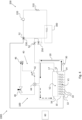
- Fig. 5 illustrates the cooling arrangement 1000 of Fig. 3 when operating in the cooling mode.
- Cooling system 1000 in the cooling mode results in relatively cool heat transfer fluid (dashed arrows) flowing to the cooling system 200 past the one or more devices 300 for cooling thereof.
- Relatively warm heat transfer fluid (complete arrows) is stored in the first volume V1 of the tank 10 and the partition 12 of the energy storage tank 10 moves towards the minimum energy storage position.
- Control of the cooling mode operation involves controlling the valve arrangement 52, 54 to allow flow of heat transfer fluid between the energy storage system 100 and the cooling system 200 to provide the cooling mode and controlling the valve arrangement 52, 54 to hinder flow of heat transfer fluid between the energy storage system 100 and the cooling system 200 to hinder the cooling mode.
- the control of the valve arrangement 52, 54 may for example use a request for cooling of the one or more devices 300 as an input. Further, the control of the valve arrangement may use an indication that cooled transfer fluid is available as input. For example, the control of the valve arrangement may use a location of the partition 12 in the storage tank 10 as an input.
- Control of the energy storage mode may comprise controlling the fluid flow control means 30 and/or the heat transfer element 40, as explained in the above.
- recuperated energy from an event in a vehicle such as a braking event may be stored until there is a need for cooling the one or more devices 300.
- the energy storage system may comprise a sensor for determining the position of the partition 12 in the tank.
- a signal from such a sensor may be used as input for controlling the energy storage system. For example, when the partition 12 is at the maximum energy storage position, the cooling state may be initiated.
- the cooling system 200 may comprise a temperature sensor 250 for sensing the temperature of the cooling fluid before reaching the device 300 to be cooled. Based on the temperature sensed by the sensor 250, a request for cooling of the device 300 may be made. Thus, the operation of the cooling arrangement 1000 may be controlled.
- Other sensors such as temperature sensors and/or flow sensors may be applied in different variants.
- the arrangement of the flow conduits for the transfer fluid may be varied.
- the storage tank 10 is provided with a first volume outlet 14 and a second volume inlet 16 connected to the transfer fluid duct 20.
- the storage tank is provided with a second volume outlet 17 and a first volume inlet 13 for connection to the cooling system 200.
- conduits for the heat transfer fluid and/or inlets/outlets to the heat transfer tank 1 may be envisaged, optionally using valves controllable to arrive at the desired fluid flows.
Landscapes
- Engineering & Computer Science (AREA)
- Mechanical Engineering (AREA)
- Transportation (AREA)
- General Engineering & Computer Science (AREA)
- Sustainable Energy (AREA)
- Power Engineering (AREA)
- Life Sciences & Earth Sciences (AREA)
- Sustainable Development (AREA)
- Physics & Mathematics (AREA)
- Thermal Sciences (AREA)
- Chemical & Material Sciences (AREA)
- Combustion & Propulsion (AREA)
- Electric Propulsion And Braking For Vehicles (AREA)
- Cooling, Air Intake And Gas Exhaust, And Fuel Tank Arrangements In Propulsion Units (AREA)
- Air-Conditioning For Vehicles (AREA)
Abstract
said partition (12) is movable to/from any position between a minimum energy storage position corresponding to a minimum second volume (V2), and a maximum energy storage position corresponding to a maximum second volume (V2),
said energy storage tank further comprising a biasing device (18) being arranged such that movement of the partition (12) away from said minimum energy storage position corresponds to storing energy in said biasing device (18), and movement towards the minimum energy storage position corresponds to releasing energy from said biasing device (18); said energy storage system further comprising a heat transfer fluid duct (20) connecting said first volume (V1) and said second volume (V2), and
a heat transfer arrangement (40) arranged for altering the temperature of the transfer fluid from a first temperature when in the first volume (V1) to a second temperature when in the second volume (V2),
and said energy storage system (100) further comprising a fluid control assembly (30) for providing a pressure implying a flow of said heat transfer fluid from said first volume (V1) to said second volume (V2) via said heat transfer fluid duct (20).
Description
- The present disclosure relates an energy storage system for a vehicle, to a cooling arrangement for a vehicle comprising an energy storage system, and to a method for energy storage of recuperation energy from an energy recuperating arrangement in a vehicle, such as from a braking arrangement in a vehicle.
- In a vehicle, for example a heavy vehicle such as a truck or bus, a need for recuperating energy from various devices or arrangements in the vehicle may arise. One example is braking energy released during regenerative braking of the vehicle.
- There is a general desire to recuperate energy wherever possible in a vehicle.
- The need for recuperating energy arises in vehicles with combustion engines as well as in wholly or partly electric vehicles, comprising an electric machine and/or an electric supply system for propulsion of the vehicle or for assisting the propulsion of the vehicle. For example, in vehicles having a battery, it is possible to recuperate energy e.g. by storage of energy in the battery
- Further, in vehicles having electric energy supply systems in the form of fuel cell systems, there is a frequent need for cooling the fuel cell system in order to maintain a nominal operation temperature of the fuel cell system.
- In view of the above, there is a need for alternatives and/or improvements relating to the recuperation of energy in vehicles, such as the recuperation of braking energy in vehicles. Further, there is a need for such alternatives and/or improvements that are available for vehicles comprising electrical energy supply systems. Another need is for alternatives and/or improvements relating to the cooling of various arrangements in a vehicle, in particular for cooling of a fuel cell system in a vehicle.
- An object of the invention is to provide an alternative and/or an improvement relating to one or more of the needs as set out in the above.
- The object is achieved by an energy storage system for a vehicle according to
claim 1. - Thus, there is provided an energy storage system for a vehicle, comprising an energy storage tank defining a tank volume for a heat transfer fluid, and comprising a partition dividing the tank volume into a first volume and a second volume, wherein the partition is movable to/from any position between a minimum energy storage position corresponding to a minimum second volume, and a maximum energy storage position corresponding to a maximum second volume, the energy storage tank further comprising a biasing device being arranged such that movement of the partition away from the minimum energy storage position corresponds to storing energy in the biasing device, and movement towards the minimum energy storage position corresponds to releasing energy from the biasing device; the energy storage system further comprising
- a heat transfer fluid duct connecting the first volume and the second volume, and
- a heat transfer arrangement arranged for altering the temperature of the heat transfer fluid from a first temperature when in the first volume to a second temperature when in the second volume
- Thus, the proposed energy storage system provides for storage of energy in two forms using the energy storage tank. First, thermal energy may be stored by means of the heat transfer arrangement heating/cooling the heat transfer fluid stored in the second volume. Second, mechanical energy may be stored by means of the biasing device storing energy when moved towards the maximum energy storage position as heat transfer fluid flows into the second volume.
- Accordingly, recuperated energy may be used for driving the heat transfer arrangement and/or the fluid control assembly, resulting in the recuperated energy being stored in the energy storage tank in the form of thermal energy and energy stored by the biasing device.
- Optionally, the heat transfer arrangement is arranged along the heat transfer fluid duct. Thus, efficient altering of the temperature of the heat transfer fluid may take place along the passage of the heat transfer fluid flow from the first volume to the second volume.
- Optionally, the fluid control assembly and/or heat transfer arrangement are configured to be driven by recuperated energy from an energy recuperating arrangement.
- Optionally, the energy recuperating arrangement is a braking arrangement. Thus, the energy storage system may be used for recuperating the braking energy from a braking arrangement in a vehicle, such as in a vehicle comprising an electric machine and/or an electric supply system for propulsion of the vehicle or for assisting the propulsion of the vehicle..
- Optionally, the one or more heat transfer arrangement is a cooling arrangement for cooling the heat transfer fluid. This implies that the heat transfer fluid in the second volume has a lower temperature than the heat transfer fluid in the first volume. In other words, the maximum energy storage position corresponding to a maximum second volume corresponds to a maximum cool storage position. This enables use of the stored thermal energy for cooling, such as in a cooling arrangement, for example a cooling arrangement in a vehicle.
- In other options however, the one or more heat transfer element may be a heating element for heating the heat transfer fluid. This implies that the heat transfer fluid in the second volume has a higher temperature than the heat transfer fluid in the first volume, and that the maximum energy storage position corresponds to a maximum heat storage position. In this case, the stored thermal energy may instead be used for heating.
- Optionally, the heat transfer arrangement comprises one or more cooling elements.
- Optionally, at least one of the one or more cooling elements is a compressor for cooling the heat transfer fluid. Thus, in this example, the compressor may be driven by recuperated energy.
- As mentioned above, the fluid control assembly is arranged for providing a pressure implying a flow of heat transfer fluid from the first volume to the second volume via the one or more heat transfer elements. Thus, the fluid control assembly may be any device suitable for providing a pressure implying such a flow. The pressure thus needs to overcome a counter-pressure provided by the biasing device of the energy storage tank, so as to enable flow of heat transfer fluid from the first volume to the second volume while moving the partition towards the maximum energy storage position and storing energy in the biasing device.
- Optionally, the fluid control assembly may be wholly or partly driven by recuperated energy.
- For example, the fluid control assembly may comprise a pump. As such, the pump may be driven by recuperated energy.
- Optionally or additionally, the fluid control assembly may comprise an actuator. Such an actuator may be arranged to act on the partition and/or the biasing device so as act in a direction for moving the partition towards the maximum energy storage position and storing energy in the biasing device.
- Optionally, the energy storage system comprises a control unit adapted to control the fluid control assembly and/or heat transfer arrangement.
- In a second aspect, the object is achieved by a cooling arrangement according to
claim 10. Accordingly, there is provided a cooling arrangement comprising an energy storage system according to any one of the preceding claims, the cooling arrangement further comprising a cooling system for cooling one or more devices using the heat transfer fluid, and a valve arrangement for controlling a flow of heat transfer fluid from the second volume to the first volume via the cooling system. - Optionally, the cooling system comprises a cooling system fluid duct connecting the second volume and the first volume, wherein the one or more devices is/are arranged along the cooling system fluid duct.
- The cooling system fluid duct may be at least partly separate from the heat transfer fluid duct of the energy storage system. With "at least partly separate" means that the cooling system fluid duct comprises at least a portion which is not also a part of the heat transfer fluid duct. In this case, the energy storage tank may for example be provided with a first volume inlet/outlet and a second volume inlet/outlet, wherein the inlet/outlets allow flow in different directions when used to provide the heat transfer fluid duct or the cooling system fluid duct, respectively.
- Optionally, the cooling system fluid duct may be completely separate from the heat transfer fluid duct of the energy storage system. With "completely separate" is meant that the cooling system fluid duct comprises no portion which is also a part of the heat transfer fluid duct. In this case, the energy storage tank may for example be provided with a first volume outlet and a second volume inlet connected to the heat transfer fluid duct, and with a first volume inlet and a second volume outlet connected to the cooling system fluid duct. Thus, by the separate ducts, each duct will allow transfer fluid flow in one direction only, hence facilitating arrangements of valves, pumps etc. along the ducts.
- Optionally, one of the one or more devices is an electrical energy supply system, such as a fuel cell system. Thus, the cooling system may be a cooling system for cooling at least one fuel cell system using the heat transfer fluid.
- Optionally, the cooling system may comprise a control unit adapted to control the valve arrangement. For example, as mentioned in the above, the energy storage system may comprise a control unit, and this control unit may be arranged so as to control also the valve arrangement of the cooling system.
- In a third aspect, the object is achieved by a method for energy storage of recuperation energy according to
claim 13. Hence, there is provided a method for energy storage of recuperation energy from an energy recuperating arrangement, in an energy storage system according to the first aspect and/or a cooling arrangement according to the second aspect. The method comprises: - using the recuperation energy for driving the fluid flow control assembly to provide a heat transfer fluid flow from the first volume to the second volume
, and/or - using the recuperation energy for driving the heat transfer element to alter the temperature of the heat transfer fluid.
- In a fourth aspect, there is provided a method for cooling one or more devices in a cooling arrangement according to the second aspect, the method comprising:
- controlling the valve arrangement to allow flow of heat transfer fluid from the second volume to the first volume of the energy storage system via the cooling system.
- In a fifth aspect, the object is achieved by a method for controlling a cooling arrangement according to the second aspect, according to claim 15. Hence, there is provided a method for controlling a cooling arrangement according to the second aspect comprising
- when recuperation energy from an energy recuperating arrangement is available, operating the cooling arrangement in an energy recuperation mode by performing the method according to the third aspect, and
- when a need for cooling the one or more devices is present, operating the cooling arrangement in a cooling mode by performing the method according to the fourth aspect.
- The method may involve selectively running one of the energy recuperation mode and the cooling mode.
- The method may comprise using information indicative of the availability of recuperation energy as input for determining when to operate the cooling arrangement in the energy recuperation mode.
- The method may comprise using information indicative of the need for cooling the one or more devices as input for determining when to operate the cooling arrangement in the cooling mode.
- Further, the method may comprise operating the cooling arrangement in the energy recuperation mode while the partition is in other than the maximum energy storage position.
- Further, the method may comprise operating the cooling arrangement in the cooling mode while the partition is in other than the minimum energy storage position.
- Hence, the method may comprise using information regarding the position of the partition in the energy storage tank as input.
- In a sixth aspect, the object is achieved by a control unit according to
claim 16. Hence, there is provided a control unit configured for performing any one of the methods described herein. - In a seventh aspect, the object is achieved by a vehicle comprising an energy storage system according to the first aspect and/or a cooling arrangement according to the second aspect, wherein preferably the fluid control assembly and/or cooling arrangement are configured to be driven by recuperated energy from a braking arrangement of the vehicle.
- Optionally, the vehicle comprises and/or is arranged to communicate with a control unit according to the sixth aspect.
- Features and advantages as described in relation to the disclosure in the above will be equally applicable to the application of the method for other vehicle arrangements than those described herein.
- Further advantages and advantageous features of the invention are disclosed in the following description and in the dependent claims.
- With reference to the appended drawings, below follows a more detailed description of embodiments of the invention cited as examples.
- In the drawings:
-
Fig. 1 is a schematic view of an example of a vehicle according to the seventh aspect for which the first to sixth aspects may be implemented; -
Fig. 2 schematically illustrates a variant of an energy storage system according to the first aspect; -
Fig. 3 schematically illustrates a variant of a cooling arrangement according to the second aspect, comprising the energy storage system ofFig. 2 ; -
Fig. 4 is a diagram schematically illustrating the cooling arrangement ofFig. 3 when operated in an energy recuperation mode; and -
Fig. 5 is a diagram schematically illustrating the cooling arrangement ofFig. 4 when operated in a cooling mode. -
Fig. 1 illustrates a variant of avehicle 1 as disclosed herein for which the invention as disclosed herein may be implemented. The invention can be applied in any vehicle, such as in a boat or car. For example, the invention can be applied in heavy-duty vehicles, such as trucks, buses and construction equipment. Although the invention will be described herein with respect to a truck, the invention is not restricted to this particular vehicle, but may also be used in other vehicles such as working machines or buses. - During operation of a vehicle such as the
vehicle 1, the need for recuperating energy from various systems and/or devices in thevehicle 1 may occur. For example, and as schematically illustrated inFig. 1 , thevehicle 1 may comprise abraking system 400 which, when in use for braking, will absorb energy which may need to be either recuperated or dissipated. - The
vehicle 1 may comprise a propulsion system comprising a combustion engine and/or an electrical energy supply system such as a battery and/or a fuel cell system. Purely by example, in the illustratedvehicle 1, the propulsion system comprises afuel cell system 300. - Also, in a
vehicle 1 such as the illustrated vehicle, a need for cooling various devices will occur during operation of thevehicle 1. To this end, thevehicle 1 may comprise acooling system 200 using a heat transfer fluid to cool one or more devices in thevehicle 1. - For example, for a
vehicle 1 comprising afuel cell system 300, as exemplified inFig, 1 , there is often a need for cooling thefuel cell system 300 during operation of thevehicle 1. - Further, the
vehicle 1 comprises anenergy storage system 100 as will be described in the below. For example, and as illustrated inFig. 1 , theenergy storage system 100 may be used in a cooling arrangement together with thecooling system 200, for recuperating energy from a system in thevehicle 1 such as thebraking system 400. Further, thecooling system 200 may be arranged for cooling thefuel cell system 300, as will also be described in the below. -
Fig. 2 illustrates schematically an example of anenergy storage system 100 according to the first aspect, which may be used for recuperating energy from a system such as abraking system 400 in avehicle 1. - The
energy storage system 100 comprises anenergy storage tank 10 defining a tank volume for a heat transfer fluid. Theenergy storage tank 10 comprises apartition 12 dividing the tank volume into a first volume V1 and a second volume V2. - The
partition 12 is movable to/from any position between a minimum energy storage position corresponding to a minimum second volume V2, and a maximum energy storage position corresponding to a maximum second volume V2. - The
tank 10 as such, and the first and second volumes V1, V2 are suitably isolated so as to enable the heat transfer fluid in said first and second volumes V1, V2, respectively, to be maintained at a relatively constant temperature over substantial periods of time. - The
energy storage tank 10 further comprises a biasingdevice 18 being arranged such that movement of thepartition 12 away from the minimum energy storage position corresponds to storing energy in thebiasing device 18, and movement towards the minimum energy storage position corresponds to releasing energy from the biasingdevice 18. - For example, the biasing
device 18 may comprise one or more spring element(s) arranged so as to bias thepartition 12 towards the minimum energy storage position. Hence, the spring element(s) are arranged such that movement of thepartition 12 away from the minimum energy storage position corresponds to storing energy in thebiasing device 18, and movement towards the minimum energy storage position corresponds to releasing energy from the biasingdevice 18, as outlined in the above. - The spring element(s) may for example be one or more compression springs or tension springs.
- The
energy storage system 100 further comprises a heattransfer fluid duct 20 connecting the first volume V1 and the second volume V2. - For example, and as illustrated in
Fig. 2 , the heattransfer fluid duct 20 may be communicating with the first volume V1 via a first volume inlet/outlet 14 and with the second volume V2 via a second volume inlet/outlet 16. - Also, the
energy storage system 100 comprises afluid control assembly 30 for providing a pressure implying a flow of heat transfer fluid from the first volume V1 to the second volume V2 though the heattransfer fluid duct 20. - The pressure provided by the
fluid control assembly 30 will work against the bias of the biasingdevice 18 so as to move thepartition 12 towards the maximum energy storage position while storing energy in thebiasing device 18. Accordingly, thefluid control assembly 30 provides for the storage of energy in mechanical form in thebiasing device 18. As such, thefluid control assembly 30 may be arranged to be driven by recuperated energy from an energy recuperation arrangement. For example, thefluid control assembly 30 may be driven by energy recuperated from a braking arrangement such as thebraking arrangement 400 in thevehicle 1 ofFig. 1 . - The
fluid control assembly 30 may for example, and as in the variant ofFig. 2 , be a pump. The pump may be adapted to provide a pressure of the heat transfer fluid being sufficient to accomplish the movement of thepartition 12 towards the maximum energy storage position while storing energy in thebiasing device 18. - Also, the
energy storage system 100 comprises aheat transfer arrangement 40 arranged for altering the temperature of the heat transfer fluid from a first temperature when in the first volume V1 to a second temperature when in the second volume V2. The flow of heat transfer fluid from the first volume V1 to the second volume V2 resulting by the action of thefluid control assembly 30 will flow through the heattransfer fluid duct 20 via theheat transfer arrangement 40, thus allowing for the storage of energy in the form of thermal energy in the heat transfer fluid. As such, theheat transfer arrangement 40 may be arranged to be driven by recuperated energy from an energy recuperating arrangement. For example, theheat transfer arrangement 40 may be driven by energy recuperated from a braking arrangement such as thebraking arrangement 400 in thevehicle 1 ofFig. 1 . - The thermal energy may be used by exploiting a temperature difference between the heat transfer fluid of the second volume V2 and another device, e.g. a device to be cooled/heated by the heat transfer fluid from the second volume V2. As such, storage of thermal energy may be made by heating the heat transfer fluid, i.e. by altering the temperature from a first temperature when in the first volume V1 to a second temperature when in the second volume V2, and where the second temperature is higher than the first temperature. Alternatively, the storage of thermal energy may be made by cooling the heat transfer fluid, i.e. where the second temperature is lower than the first temperature. As will be described in the below, the alternative to cool the heat transfer fluid may be particularly useful when combined with a cooling system for use in a vehicle.
- The
heat transfer arrangement 40 may be arranged anywhere allowing for altering of the temperature of the heat transfer fluid in or flowing to the second volume V2, in relation to the temperature of the heat transfer fluid in the first volume V1. - Optionally, and as in the variant illustrated in
Fig. 2 , the heat transfer arrangement is arranged along the heattransfer fluid duct 20. As such, the heat transfer arrangement may be arranged to alter the temperature of the heat transfer fluid when flowing through the heat transfer fluid duct towards the second volume V2. This arrangement allows for various options when it comes to realising theheat transfer arrangement 40. - That the
heat transfer arrangement 40 is an arrangement for cooling the heat transfer fluid may be suitable for applications in which it is desired to use the cooled heat transfer fluid from the second volume V2 of the energystorage fuel tank 10 i.e. for a cooling arrangement, as will be described in the below with reference toFig. 3 . For example in vehicle applications, thestorage system 100 enables storing recuperated energy from an energy recuperating arrangement, such as from abraking arrangement 400, and using the stored energy for cooling purposes such as in acooling system 200 for cooling one or more devices, for example for cooling afuel cell system 300. - However, as intimated in the above, the
heat transfer arrangement 40 could in other applications be an arrangement for heating the heat transfer fluid, in which case the heat transfer fluid in the second volume V2 has a higher temperature than the heat transfer fluid in the first volume V1 (i.e. the second temperature is higher than the first temperature). In other words, the maximum energy storage position corresponding to a maximum second volume V2 corresponds to a maximum hot storage position. In this case, the heated heat transfer fluid from the second volume V2 of the energy storage fuel tank may be used i.e. for a heating arrangement. - The
heat transfer arrangement 40 may, as exemplified inFig. 2 , comprise a heat transfer circuit arranged for altering the temperature of the heat transfer fluid in the heattransfer fluid duct 20 between the first volume V1 and the second volume V2. The heat transfer circuit may comprise one or more heat transfer elements. - For example, and as illustrated in
Fig. 2 , theheat transfer arrangement 40 may comprise aheat transfer circuit 40 for cooling the heat transfer fluid comprising one or more heat transfer elements such as anevaporator 44 and/or acompressor 42. For example, theheat transfer arrangement 40 may, as illustrated inFig. 2 , comprise anevaporator 44, acompressor 42, acondenser 46 and anexpansion valve 48. One or more of the devices of theheat transfer arrangement 40 may be driven by recuperated energy, for example thecompressor 42 in the exemplifiedheat transfer arrangement 40 may be driven by recuperated energy. - The
energy storage system 100 may further comprise acontrol unit 60 adapted to control thefluid control assembly 30 and/orheat transfer arrangement 40. Such acontrol unit 60 may be arranged to communicate with thefluid control assembly 30 and/orheat transfer arrangement 40 via wired or wireless transmission. When theenergy storage system 100 is arranged in avehicle 1, thecontrol unit 60 may be arranged in thevehicle 1 or remote from thevehicle 1. - For example, when the
energy storage system 100 is arranged in avehicle 1 comprising abraking system 400, thecontrol unit 60 may be adapted to control thefluid control assembly 30 and/orheat transfer arrangement 40 to operate when energy from thebraking system 400 is available, and/or not to operate when no energy from the braking system is available. - As explained in the above, storage of energy in the
energy storage system 100 takes place by operating theheat transfer arrangement 40 and/or thefluid control arrangement 30. By operation of thefluid control arrangement 30, a fluid flow from the first volume V1 to the second volume V2 is created. - As such, there is provided a method for energy storage of recuperation energy from an energy recuperating arrangement, such as an energy recuperating arrangement in a vehicle, in an
energy storage system 100, the method comprising: using the recuperation energy for driving the fluid flow control assembly to provide a heat transfer fluid flow from the first volume V1 to the second volume V2 and/or using the recuperation energy for driving theheat transfer element 40 to alter the temperature of the heat transfer fluid. - As mentioned in the above, the
energy storage system 100 may be connected e.g. to a cooling arrangement or to a heating arrangement arranged to use the thermal energy stored in the heat transfer fluid in the second volume V2. -
Fig. 3 illustrates a variant of acooling arrangement 1000 comprising anenergy storage system 100 as described in relation toFig. 2 , and acooling system 200 for cooling one ormore devices 300 using the heat transfer fluid, and avalve arrangement cooling system 200. - Thus,
Fig. 3 illustrates an example of acooling arrangement 1000 according to the second aspect. In such acooling arrangement 1000, acooling system 200 is arranged to use cooled heat transfer fluid stored in the second volume V2 of thestorage tank 10 to cool one ormore devices 300. Thevalve arrangement partition 12 moves in a direction away from the maximum energy storage position, releasing mechanical energy stored in the biasing means 18. - For example, and as illustrated in
Fig. 3 , thevalve arrangement first valve 52 controlling the outlet of heat transfer fluid from thecooling system 200 to theenergy storage system 100, and asecond valve 54 controlling the inlet of heat transfer fluid to thecooling system 200 from theenergy storage system 100. As such, thefirst valve 52 is arranged to control the outlet of heat transfer fluid from thecooling system 200 to the first volume V1 of thestorage tank 10, and/or thesecond valve 54 is arranged to control the inlet of heat transfer fluid to thecooling system 200 to thecooling system 200 from the second volume V2 of thestorage tank 10. - The valves of the valve arrangement may be any valves as known in the art, for example, and as in the illustrated variant, the
first valve 52 may be a three-way valve, and thesecond valve 54 may be a flow restrictor valve. - The cooling arrangement may further comprise a
control unit 60, arranged to control thevalve arrangement energy storage system 100 and thecooling system 200 for cooling the one ormore devices 300. Advantageously, thecontrol unit 60 for controlling thevalve arrangement control unit 60 for controlling theenergy storage system 100. - The one or
more devices 300 to be cooled may be any devices in avehicle 1 which may require cooling. - For example, and as in the illustrated variant, at least one
device 300 to be cooled may be an electric energy supply system such as a battery system and fuel cell system. - Hence, by means of the cooling system as described herein, there is provided a possibility of using recuperated energy, such as recuperated braking energy which can be recuperated when braking the vehicle, for cooling an electric energy supply system in the vehicle.
- Thus, the cooling system provides an efficient solution alleviating two needs associated with vehicles comprising an electric energy supply system such as a fuel cell system, i.e. the need for recuperating energy and the need for cooling the electric energy supply system.
- The
cooling arrangement 200 may further comprise additional devices as essentially known in the art. For example, a heat transfer fluid cooling element may be arranged downstream the one ormore devices 300 to be cooled. For example, and as illustrated inFig. 4 , aheat exchanger 210, such as aheat exchanger 210 arranged at the front of a truck, may be present downstream the one ormore devices 300 to be cooled. Thus, the heat transfer fluid which when used for cooling the one ormore devices 300 will itself be heated, may thereafter be cooled by theheat exchanger 210. In another example, apump 220 may be arranged to assist the transfer fluid flow in thecooling arrangement 200. - As intimated in the above, when in use, the
cooling system 1000 may operate in two different modes: an energy recuperation mode and a cooling mode. - The energy recuperation mode is a method for energy storage of recuperation energy from an energy recuperating arrangement in a vehicle, comprising:
- using the recuperation energy for driving the fluid
flow control assembly 30 toprovide a heat transfer fluid flow from the first volume V1 to the second volume V2 of thestorage tank 10 and - using the recuperation energy for driving the
heat transfer element 40 to cool the heat transfer fluid. -
Fig. 4 illustrates thecooling arrangement 1000 ofFig. 3 when operating in the energy recuperation mode. - Operating the
cooling system 1000 in the energy recuperation mode results relatively warm heat transfer fluid (complete arrows) flowing past theheat transfer arrangement 40 such that relatively cool heat transfer fluid (dashed arrows) is stored in the second volume V2 and thepartition 12 of theenergy storage tank 10 moves towards the maximum energy storage position. - The cooling mode is a method for cooling the one or
more devices 300 in thecooling system 200 and comprises allowing transfer fluid flow between theenergy storage system 100 and thecooling system 200 so as to cool the one ormore devices 300. -
Fig. 5 illustrates thecooling arrangement 1000 ofFig. 3 when operating in the cooling mode. - Operating the
cooling system 1000 in the cooling mode results in relatively cool heat transfer fluid (dashed arrows) flowing to thecooling system 200 past the one ormore devices 300 for cooling thereof. Relatively warm heat transfer fluid (complete arrows) is stored in the first volume V1 of thetank 10 and thepartition 12 of theenergy storage tank 10 moves towards the minimum energy storage position. - Control of the cooling mode operation involves controlling the
valve arrangement energy storage system 100 and thecooling system 200 to provide the cooling mode and controlling thevalve arrangement energy storage system 100 and thecooling system 200 to hinder the cooling mode. - The control of the
valve arrangement more devices 300 as an input. Further, the control of the valve arrangement may use an indication that cooled transfer fluid is available as input. For example, the control of the valve arrangement may use a location of thepartition 12 in thestorage tank 10 as an input. - Control of the energy storage mode may comprise controlling the fluid flow control means 30 and/or the
heat transfer element 40, as explained in the above. - Thus, recuperated energy from an event in a vehicle, such as a braking event may be stored until there is a need for cooling the one or
more devices 300. - Other options and alternatives of the systems, arrangements and methods as described herein may be envisaged by those skilled in the art.
- For example, the energy storage system may comprise a sensor for determining the position of the
partition 12 in the tank. A signal from such a sensor may be used as input for controlling the energy storage system. For example, when thepartition 12 is at the maximum energy storage position, the cooling state may be initiated. - For example, and as illustrated in
Figs. 3 to 5 , thecooling system 200 may comprise atemperature sensor 250 for sensing the temperature of the cooling fluid before reaching thedevice 300 to be cooled. Based on the temperature sensed by thesensor 250, a request for cooling of thedevice 300 may be made. Thus, the operation of thecooling arrangement 1000 may be controlled. Other sensors such as temperature sensors and/or flow sensors may be applied in different variants. - Also, the arrangement of the flow conduits for the transfer fluid may be varied. For example, in
Figs. 3 to 5 , thestorage tank 10 is provided with afirst volume outlet 14 and asecond volume inlet 16 connected to thetransfer fluid duct 20. In addition, the storage tank is provided with asecond volume outlet 17 and afirst volume inlet 13 for connection to thecooling system 200. - However, in other variants, different arrangements of conduits for the heat transfer fluid and/or inlets/outlets to the
heat transfer tank 1 may be envisaged, optionally using valves controllable to arrive at the desired fluid flows.
Claims (18)
- An energy storage system (100) for a vehicle, comprising an energy storage tank (10) defining a tank volume for a heat transfer fluid, and comprising a partition (12) dividing said tank volume into a first volume (V1) and a second volume (V2), whereinsaid partition (12) is movable to/from any position between a minimum energy storage position corresponding to a minimum second volume (V2), and a maximum energy storage position corresponding to a maximum second volume (V2),said energy storage tank further comprising a biasing device (18) being arranged such that movement of said partition (12) away from said minimum energy storage position corresponds to storing energy in said biasing device (18), and movement towards said minimum energy storage position corresponds to releasing energy from said biasing device (18); said energy storage system further comprisingand said energy storage system (100) further comprising a fluid control assembly (30) for providing a pressure implying a flow of said heat transfer fluid from said first volume (V1) to said second volume (V2) via said heat transfer fluid duct (20).- a heat transfer fluid duct (20) connecting said first volume (V1) and said second volume (V2), and- a heat transfer arrangement (40) arranged for altering the temperature of said transfer fluid from a first temperature when in said first volume (V1) to a second temperature when in said second volume (V2),
- The energy storage system according to claim 1, wherein said heat transfer arrangement (40) is arranged along said heat transfer fluid duct (20).
- The energy storage system according to any one of the preceding claims, wherein said fluid control assembly (30) and/or heat transfer arrangement (40) are configured to be driven by recuperated energy from an energy recuperating arrangement.
- The energy storage system according to claim 3, wherein said energy recuperating arrangement is a braking arrangement.
- The energy storage system according to any one of the preceding claims, wherein said heat transfer arrangement (40) is a cooling arrangement for cooling said heat transfer fluid.
- The energy storage system according to claim 5, wherein said heat transfer arrangement (40) comprises one or more cooling elements.
- The energy storage system according to claim 6, wherein at least one out of said one or more cooling elements is a compressor (42) for cooling said heat transfer fluid.
- The energy storage system according to any one of the preceding claims, wherein said fluid control assembly (30) comprises a pump and/or an actuator.
- The energy storage system according to any one of the preceding claims, further comprising a control unit (60) adapted to control said fluid control assembly (30) and/or heat transfer arrangement (40).
- Cooling arrangement (1000) comprising an energy storage system (100) according to any one of the preceding claims, said cooling arrangement (1000) further comprising a cooling system (200) for cooling one or more devices (300) using said heat transfer fluid, and a valve arrangement (52, 54) for controlling a flow of heat transfer fluid from said second volume (V2) to said first volume (V1) via said cooling system (200).
- The cooling arrangement (1000) according to claim 10, wherein said cooling system (200) comprises a cooling system fluid duct connecting said second volume (V2) and said first volume (V1), wherein said one or more devices (300) is arranged along said cooling system fluid duct (250).
- The cooling arrangement (1000) according to claim 10 or 11, wherein one of said one or more devices (300) is an electrical energy supply system, such as a fuel cell system (300) and/or a battery
- Method for energy storage of recuperation energy from an energy recuperating arrangement in a vehicle, in an energy storage system according to any one of the claims 1 to 9 and/or a cooling arrangement according to any one of the claims 10 to 12, the method comprising:
using said recuperation energy for driving said fluid flow control assembly (30) to provide a heat transfer fluid flow from said first volume (V1) to said second volume (V2)and/or- using said recuperation energy for driving said heat transfer element (40) to alter the temperature of said heat transfer fluid. - Method for cooling one or more devices in a cooling arrangement
according to any one of the claims 10 to 12, the method comprising controlling said valve arrangement (52, 54) to allow flow of heat transfer fluid from said second volume (V2) to said first volume (V1) of said energy storage system (100) via said cooling system (200). - Method for controlling a cooling arrangement according to any one of the claims 10 to 12, the method comprising- When recuperation energy from an energy recuperating arrangement is available, operating the cooling arrangement in an energy recuperation mode by performing the method according to claim 13, wherein said second temperature is lower than said first temperature; and- When a need for cooling said one or more devices (300) is present, operating said cooling arrangement in a cooling mode by performing the method according to claim 14.
- Control unit configured for performing any one of the methods according to claims 13 to 15.
- Vehicle comprising an energy storage system (100) according to any one of the claims 1 to 8 and/or a cooling arrangement (1000) according to any one of the claims 9 to 10, wherein preferably said fluid control assembly (30) and/or cooling element (40) are configured to be driven by recuperated energy from a braking arrangement of said vehicle.
- Vehicle according to claim 16, said vehicle comprising and/or being arranged to communicate with a control unit (60) according to claim 15.
Priority Applications (3)
| Application Number | Priority Date | Filing Date | Title |
|---|---|---|---|
| EP21200843.7A EP4163163B1 (en) | 2021-10-05 | 2021-10-05 | Energy storage system and cooling arrangment for a vehicle and methods |
| US17/954,586 US12281852B2 (en) | 2021-10-05 | 2022-09-28 | Energy storage system and cooling arrangement for a vehicle |
| CN202211202144.6A CN115923524A (en) | 2021-10-05 | 2022-09-29 | Energy storage system and cooling device for vehicle |
Applications Claiming Priority (1)
| Application Number | Priority Date | Filing Date | Title |
|---|---|---|---|
| EP21200843.7A EP4163163B1 (en) | 2021-10-05 | 2021-10-05 | Energy storage system and cooling arrangment for a vehicle and methods |
Publications (2)
| Publication Number | Publication Date |
|---|---|
| EP4163163A1 true EP4163163A1 (en) | 2023-04-12 |
| EP4163163B1 EP4163163B1 (en) | 2025-01-29 |
Family
ID=78078087
Family Applications (1)
| Application Number | Title | Priority Date | Filing Date |
|---|---|---|---|
| EP21200843.7A Active EP4163163B1 (en) | 2021-10-05 | 2021-10-05 | Energy storage system and cooling arrangment for a vehicle and methods |
Country Status (3)
| Country | Link |
|---|---|
| US (1) | US12281852B2 (en) |
| EP (1) | EP4163163B1 (en) |
| CN (1) | CN115923524A (en) |
Citations (1)
| Publication number | Priority date | Publication date | Assignee | Title |
|---|---|---|---|---|
| DE112018004389T5 (en) * | 2017-10-13 | 2020-05-14 | Scania Cv Ab | Retarder device, drive train, vehicle and method for operating a retarder device |
Family Cites Families (1)
| Publication number | Priority date | Publication date | Assignee | Title |
|---|---|---|---|---|
| US10297880B2 (en) | 2016-04-20 | 2019-05-21 | Ford Global Technologies, Llc | Battery thermal management system |
-
2021
- 2021-10-05 EP EP21200843.7A patent/EP4163163B1/en active Active
-
2022
- 2022-09-28 US US17/954,586 patent/US12281852B2/en active Active
- 2022-09-29 CN CN202211202144.6A patent/CN115923524A/en active Pending
Patent Citations (1)
| Publication number | Priority date | Publication date | Assignee | Title |
|---|---|---|---|---|
| DE112018004389T5 (en) * | 2017-10-13 | 2020-05-14 | Scania Cv Ab | Retarder device, drive train, vehicle and method for operating a retarder device |
Also Published As
| Publication number | Publication date |
|---|---|
| US20230105750A1 (en) | 2023-04-06 |
| US12281852B2 (en) | 2025-04-22 |
| CN115923524A (en) | 2023-04-07 |
| EP4163163B1 (en) | 2025-01-29 |
Similar Documents
| Publication | Publication Date | Title |
|---|---|---|
| CN110315928B (en) | Vehicle thermal system low to high quality energy management, storage, recovery and optimization | |
| CN1727814B (en) | Hybrid Vehicle Environmental Control System Using Thermoelectric Elements | |
| US11407282B2 (en) | Installation for the thermal conditioning of a passenger compartment and/or at least one component of a motor vehicle | |
| US9780422B2 (en) | Cabin and battery cooling control for electrified vehicles | |
| EP2349757B1 (en) | Method and system for cooling and warming | |
| CN100408367C (en) | Air Conditioning System | |
| EP3878670B1 (en) | In-vehicle temperature control system | |
| CN101633306B (en) | Vehicle HVAC and RESS thermal management | |
| CN101712274B (en) | Hybrid electric vehicle | |
| JP2013254725A (en) | Heating/cooling system for battery of motor vehicle, and operating method for the same | |
| KR950003701B1 (en) | Air conditioner for vehicle | |
| EP2409864B1 (en) | Automotive air-conditioning system | |
| US20170174039A1 (en) | Method and Air Conditioning Unit for Air Conditioning an Interior of an Electrically Driven Vehicle | |
| KR20180065311A (en) | Vehicle thermal management system | |
| US10549605B2 (en) | Heating system and method for heating a vehicle interior of a vehicle having an internal combustion engine | |
| KR101588767B1 (en) | Air conditioner system control method for vehicle | |
| CN103748347A (en) | Rankine cycle | |
| CN104412445B (en) | Motor vehicle with battery cooling system | |
| CN115768636A (en) | Thermal management system for an electric vehicle and method for the operation thereof | |
| US20150315956A1 (en) | Cooling system for a mechanically and hydraulically powered hybrid vehicle | |
| EP3549799B1 (en) | A vehicle thermal management system | |
| EP2665612B1 (en) | Motor vehicle | |
| US12350997B2 (en) | Heat transfer fluid system for a vehicle | |
| JP2013245457A (en) | Hybrid type construction machine | |
| CN103032990A (en) | Rankine cycle system |
Legal Events
| Date | Code | Title | Description |
|---|---|---|---|
| PUAI | Public reference made under article 153(3) epc to a published international application that has entered the european phase |
Free format text: ORIGINAL CODE: 0009012 |
|
| STAA | Information on the status of an ep patent application or granted ep patent |
Free format text: STATUS: THE APPLICATION HAS BEEN PUBLISHED |
|
| AK | Designated contracting states |
Kind code of ref document: A1 Designated state(s): AL AT BE BG CH CY CZ DE DK EE ES FI FR GB GR HR HU IE IS IT LI LT LU LV MC MK MT NL NO PL PT RO RS SE SI SK SM TR |
|
| STAA | Information on the status of an ep patent application or granted ep patent |
Free format text: STATUS: REQUEST FOR EXAMINATION WAS MADE |
|
| 17P | Request for examination filed |
Effective date: 20230926 |
|
| RBV | Designated contracting states (corrected) |
Designated state(s): AL AT BE BG CH CY CZ DE DK EE ES FI FR GB GR HR HU IE IS IT LI LT LU LV MC MK MT NL NO PL PT RO RS SE SI SK SM TR |
|
| GRAP | Despatch of communication of intention to grant a patent |
Free format text: ORIGINAL CODE: EPIDOSNIGR1 |
|
| STAA | Information on the status of an ep patent application or granted ep patent |
Free format text: STATUS: GRANT OF PATENT IS INTENDED |
|
| GRAS | Grant fee paid |
Free format text: ORIGINAL CODE: EPIDOSNIGR3 |
|
| INTG | Intention to grant announced |
Effective date: 20241120 |
|
| GRAA | (expected) grant |
Free format text: ORIGINAL CODE: 0009210 |
|
| STAA | Information on the status of an ep patent application or granted ep patent |
Free format text: STATUS: THE PATENT HAS BEEN GRANTED |
|
| AK | Designated contracting states |
Kind code of ref document: B1 Designated state(s): AL AT BE BG CH CY CZ DE DK EE ES FI FR GB GR HR HU IE IS IT LI LT LU LV MC MK MT NL NO PL PT RO RS SE SI SK SM TR |
|
| REG | Reference to a national code |
Ref country code: GB Ref legal event code: FG4D |
|
| REG | Reference to a national code |
Ref country code: CH Ref legal event code: EP |
|
| REG | Reference to a national code |
Ref country code: DE Ref legal event code: R096 Ref document number: 602021025322 Country of ref document: DE |
|
| REG | Reference to a national code |
Ref country code: IE Ref legal event code: FG4D |
|
| REG | Reference to a national code |
Ref country code: NL Ref legal event code: MP Effective date: 20250129 |
|
| PG25 | Lapsed in a contracting state [announced via postgrant information from national office to epo] |
Ref country code: NL Free format text: LAPSE BECAUSE OF FAILURE TO SUBMIT A TRANSLATION OF THE DESCRIPTION OR TO PAY THE FEE WITHIN THE PRESCRIBED TIME-LIMIT Effective date: 20250129 |
|
| PG25 | Lapsed in a contracting state [announced via postgrant information from national office to epo] |
Ref country code: RS Free format text: LAPSE BECAUSE OF FAILURE TO SUBMIT A TRANSLATION OF THE DESCRIPTION OR TO PAY THE FEE WITHIN THE PRESCRIBED TIME-LIMIT Effective date: 20250429 |
|
| PG25 | Lapsed in a contracting state [announced via postgrant information from national office to epo] |
Ref country code: FI Free format text: LAPSE BECAUSE OF FAILURE TO SUBMIT A TRANSLATION OF THE DESCRIPTION OR TO PAY THE FEE WITHIN THE PRESCRIBED TIME-LIMIT Effective date: 20250129 |
|
| PG25 | Lapsed in a contracting state [announced via postgrant information from national office to epo] |
Ref country code: PL Free format text: LAPSE BECAUSE OF FAILURE TO SUBMIT A TRANSLATION OF THE DESCRIPTION OR TO PAY THE FEE WITHIN THE PRESCRIBED TIME-LIMIT Effective date: 20250129 |
|
| PG25 | Lapsed in a contracting state [announced via postgrant information from national office to epo] |
Ref country code: ES Free format text: LAPSE BECAUSE OF FAILURE TO SUBMIT A TRANSLATION OF THE DESCRIPTION OR TO PAY THE FEE WITHIN THE PRESCRIBED TIME-LIMIT Effective date: 20250129 |
|
| REG | Reference to a national code |
Ref country code: LT Ref legal event code: MG9D |
|
| PG25 | Lapsed in a contracting state [announced via postgrant information from national office to epo] |
Ref country code: IS Free format text: LAPSE BECAUSE OF FAILURE TO SUBMIT A TRANSLATION OF THE DESCRIPTION OR TO PAY THE FEE WITHIN THE PRESCRIBED TIME-LIMIT Effective date: 20250529 Ref country code: NO Free format text: LAPSE BECAUSE OF FAILURE TO SUBMIT A TRANSLATION OF THE DESCRIPTION OR TO PAY THE FEE WITHIN THE PRESCRIBED TIME-LIMIT Effective date: 20250429 |
|
| REG | Reference to a national code |
Ref country code: AT Ref legal event code: MK05 Ref document number: 1763173 Country of ref document: AT Kind code of ref document: T Effective date: 20250129 |
|
| PG25 | Lapsed in a contracting state [announced via postgrant information from national office to epo] |
Ref country code: HR Free format text: LAPSE BECAUSE OF FAILURE TO SUBMIT A TRANSLATION OF THE DESCRIPTION OR TO PAY THE FEE WITHIN THE PRESCRIBED TIME-LIMIT Effective date: 20250129 |
|
| PG25 | Lapsed in a contracting state [announced via postgrant information from national office to epo] |
Ref country code: PT Free format text: LAPSE BECAUSE OF FAILURE TO SUBMIT A TRANSLATION OF THE DESCRIPTION OR TO PAY THE FEE WITHIN THE PRESCRIBED TIME-LIMIT Effective date: 20250529 Ref country code: LV Free format text: LAPSE BECAUSE OF FAILURE TO SUBMIT A TRANSLATION OF THE DESCRIPTION OR TO PAY THE FEE WITHIN THE PRESCRIBED TIME-LIMIT Effective date: 20250129 |
|
| PG25 | Lapsed in a contracting state [announced via postgrant information from national office to epo] |
Ref country code: GR Free format text: LAPSE BECAUSE OF FAILURE TO SUBMIT A TRANSLATION OF THE DESCRIPTION OR TO PAY THE FEE WITHIN THE PRESCRIBED TIME-LIMIT Effective date: 20250430 Ref country code: BG Free format text: LAPSE BECAUSE OF FAILURE TO SUBMIT A TRANSLATION OF THE DESCRIPTION OR TO PAY THE FEE WITHIN THE PRESCRIBED TIME-LIMIT Effective date: 20250129 |
|
| PG25 | Lapsed in a contracting state [announced via postgrant information from national office to epo] |
Ref country code: AT Free format text: LAPSE BECAUSE OF FAILURE TO SUBMIT A TRANSLATION OF THE DESCRIPTION OR TO PAY THE FEE WITHIN THE PRESCRIBED TIME-LIMIT Effective date: 20250129 |
|
| PG25 | Lapsed in a contracting state [announced via postgrant information from national office to epo] |
Ref country code: SE Free format text: LAPSE BECAUSE OF FAILURE TO SUBMIT A TRANSLATION OF THE DESCRIPTION OR TO PAY THE FEE WITHIN THE PRESCRIBED TIME-LIMIT Effective date: 20250129 |
|
| PG25 | Lapsed in a contracting state [announced via postgrant information from national office to epo] |
Ref country code: SM Free format text: LAPSE BECAUSE OF FAILURE TO SUBMIT A TRANSLATION OF THE DESCRIPTION OR TO PAY THE FEE WITHIN THE PRESCRIBED TIME-LIMIT Effective date: 20250129 |
|
| PG25 | Lapsed in a contracting state [announced via postgrant information from national office to epo] |
Ref country code: DK Free format text: LAPSE BECAUSE OF FAILURE TO SUBMIT A TRANSLATION OF THE DESCRIPTION OR TO PAY THE FEE WITHIN THE PRESCRIBED TIME-LIMIT Effective date: 20250129 |
|
| PG25 | Lapsed in a contracting state [announced via postgrant information from national office to epo] |
Ref country code: IT Free format text: LAPSE BECAUSE OF FAILURE TO SUBMIT A TRANSLATION OF THE DESCRIPTION OR TO PAY THE FEE WITHIN THE PRESCRIBED TIME-LIMIT Effective date: 20250129 |
|
| PG25 | Lapsed in a contracting state [announced via postgrant information from national office to epo] |
Ref country code: EE Free format text: LAPSE BECAUSE OF FAILURE TO SUBMIT A TRANSLATION OF THE DESCRIPTION OR TO PAY THE FEE WITHIN THE PRESCRIBED TIME-LIMIT Effective date: 20250129 Ref country code: CZ Free format text: LAPSE BECAUSE OF FAILURE TO SUBMIT A TRANSLATION OF THE DESCRIPTION OR TO PAY THE FEE WITHIN THE PRESCRIBED TIME-LIMIT Effective date: 20250129 |
|
| PG25 | Lapsed in a contracting state [announced via postgrant information from national office to epo] |
Ref country code: RO Free format text: LAPSE BECAUSE OF FAILURE TO SUBMIT A TRANSLATION OF THE DESCRIPTION OR TO PAY THE FEE WITHIN THE PRESCRIBED TIME-LIMIT Effective date: 20250129 |
|
| PG25 | Lapsed in a contracting state [announced via postgrant information from national office to epo] |
Ref country code: SK Free format text: LAPSE BECAUSE OF FAILURE TO SUBMIT A TRANSLATION OF THE DESCRIPTION OR TO PAY THE FEE WITHIN THE PRESCRIBED TIME-LIMIT Effective date: 20250129 |
|
| REG | Reference to a national code |
Ref country code: DE Ref legal event code: R097 Ref document number: 602021025322 Country of ref document: DE |
|
| PLBE | No opposition filed within time limit |
Free format text: ORIGINAL CODE: 0009261 |
|
| STAA | Information on the status of an ep patent application or granted ep patent |
Free format text: STATUS: NO OPPOSITION FILED WITHIN TIME LIMIT |
|
| 26N | No opposition filed |
Effective date: 20251030 |
|
| PGFP | Annual fee paid to national office [announced via postgrant information from national office to epo] |
Ref country code: DE Payment date: 20251028 Year of fee payment: 5 |