EP4163129A1 - Tire for rough terrain - Google Patents
Tire for rough terrain Download PDFInfo
- Publication number
- EP4163129A1 EP4163129A1 EP22197209.4A EP22197209A EP4163129A1 EP 4163129 A1 EP4163129 A1 EP 4163129A1 EP 22197209 A EP22197209 A EP 22197209A EP 4163129 A1 EP4163129 A1 EP 4163129A1
- Authority
- EP
- European Patent Office
- Prior art keywords
- tire
- crown
- main portion
- block main
- edge
- Prior art date
- Legal status (The legal status is an assumption and is not a legal conclusion. Google has not performed a legal analysis and makes no representation as to the accuracy of the status listed.)
- Granted
Links
Images



Classifications
-
- B—PERFORMING OPERATIONS; TRANSPORTING
- B60—VEHICLES IN GENERAL
- B60C—VEHICLE TYRES; TYRE INFLATION; TYRE CHANGING; CONNECTING VALVES TO INFLATABLE ELASTIC BODIES IN GENERAL; DEVICES OR ARRANGEMENTS RELATED TO TYRES
- B60C11/00—Tyre tread bands; Tread patterns; Anti-skid inserts
- B60C11/03—Tread patterns
- B60C11/0311—Patterns comprising tread lugs arranged parallel or oblique to the axis of rotation
-
- B—PERFORMING OPERATIONS; TRANSPORTING
- B60—VEHICLES IN GENERAL
- B60C—VEHICLE TYRES; TYRE INFLATION; TYRE CHANGING; CONNECTING VALVES TO INFLATABLE ELASTIC BODIES IN GENERAL; DEVICES OR ARRANGEMENTS RELATED TO TYRES
- B60C11/00—Tyre tread bands; Tread patterns; Anti-skid inserts
- B60C11/03—Tread patterns
- B60C11/0302—Tread patterns directional pattern, i.e. with main rolling direction
-
- B—PERFORMING OPERATIONS; TRANSPORTING
- B60—VEHICLES IN GENERAL
- B60C—VEHICLE TYRES; TYRE INFLATION; TYRE CHANGING; CONNECTING VALVES TO INFLATABLE ELASTIC BODIES IN GENERAL; DEVICES OR ARRANGEMENTS RELATED TO TYRES
- B60C11/00—Tyre tread bands; Tread patterns; Anti-skid inserts
- B60C11/03—Tread patterns
- B60C11/0306—Patterns comprising block rows or discontinuous ribs
- B60C11/0309—Patterns comprising block rows or discontinuous ribs further characterised by the groove cross-section
-
- B—PERFORMING OPERATIONS; TRANSPORTING
- B60—VEHICLES IN GENERAL
- B60C—VEHICLE TYRES; TYRE INFLATION; TYRE CHANGING; CONNECTING VALVES TO INFLATABLE ELASTIC BODIES IN GENERAL; DEVICES OR ARRANGEMENTS RELATED TO TYRES
- B60C11/00—Tyre tread bands; Tread patterns; Anti-skid inserts
- B60C11/03—Tread patterns
- B60C11/0311—Patterns comprising tread lugs arranged parallel or oblique to the axis of rotation
- B60C11/0316—Patterns comprising tread lugs arranged parallel or oblique to the axis of rotation further characterised by the groove cross-section
-
- B—PERFORMING OPERATIONS; TRANSPORTING
- B60—VEHICLES IN GENERAL
- B60C—VEHICLE TYRES; TYRE INFLATION; TYRE CHANGING; CONNECTING VALVES TO INFLATABLE ELASTIC BODIES IN GENERAL; DEVICES OR ARRANGEMENTS RELATED TO TYRES
- B60C11/00—Tyre tread bands; Tread patterns; Anti-skid inserts
- B60C11/03—Tread patterns
- B60C11/11—Tread patterns in which the raised area of the pattern consists only of isolated elements, e.g. blocks
-
- B—PERFORMING OPERATIONS; TRANSPORTING
- B60—VEHICLES IN GENERAL
- B60C—VEHICLE TYRES; TYRE INFLATION; TYRE CHANGING; CONNECTING VALVES TO INFLATABLE ELASTIC BODIES IN GENERAL; DEVICES OR ARRANGEMENTS RELATED TO TYRES
- B60C11/00—Tyre tread bands; Tread patterns; Anti-skid inserts
- B60C11/03—Tread patterns
- B60C11/13—Tread patterns characterised by the groove cross-section, e.g. for buttressing or preventing stone-trapping
- B60C11/1307—Tread patterns characterised by the groove cross-section, e.g. for buttressing or preventing stone-trapping with special features of the groove walls
- B60C11/1315—Tread patterns characterised by the groove cross-section, e.g. for buttressing or preventing stone-trapping with special features of the groove walls having variable inclination angles, e.g. warped groove walls
-
- B—PERFORMING OPERATIONS; TRANSPORTING
- B60—VEHICLES IN GENERAL
- B60C—VEHICLE TYRES; TYRE INFLATION; TYRE CHANGING; CONNECTING VALVES TO INFLATABLE ELASTIC BODIES IN GENERAL; DEVICES OR ARRANGEMENTS RELATED TO TYRES
- B60C11/00—Tyre tread bands; Tread patterns; Anti-skid inserts
- B60C11/03—Tread patterns
- B60C11/13—Tread patterns characterised by the groove cross-section, e.g. for buttressing or preventing stone-trapping
- B60C11/1376—Three dimensional block surfaces departing from the enveloping tread contour
-
- B—PERFORMING OPERATIONS; TRANSPORTING
- B60—VEHICLES IN GENERAL
- B60C—VEHICLE TYRES; TYRE INFLATION; TYRE CHANGING; CONNECTING VALVES TO INFLATABLE ELASTIC BODIES IN GENERAL; DEVICES OR ARRANGEMENTS RELATED TO TYRES
- B60C11/00—Tyre tread bands; Tread patterns; Anti-skid inserts
- B60C11/03—Tread patterns
- B60C11/12—Tread patterns characterised by the use of narrow slits or incisions, e.g. sipes
- B60C11/1259—Depth of the sipe
-
- B—PERFORMING OPERATIONS; TRANSPORTING
- B60—VEHICLES IN GENERAL
- B60C—VEHICLE TYRES; TYRE INFLATION; TYRE CHANGING; CONNECTING VALVES TO INFLATABLE ELASTIC BODIES IN GENERAL; DEVICES OR ARRANGEMENTS RELATED TO TYRES
- B60C11/00—Tyre tread bands; Tread patterns; Anti-skid inserts
- B60C11/03—Tread patterns
- B60C11/0311—Patterns comprising tread lugs arranged parallel or oblique to the axis of rotation
- B60C2011/0313—Patterns comprising tread lugs arranged parallel or oblique to the axis of rotation directional type
-
- B—PERFORMING OPERATIONS; TRANSPORTING
- B60—VEHICLES IN GENERAL
- B60C—VEHICLE TYRES; TYRE INFLATION; TYRE CHANGING; CONNECTING VALVES TO INFLATABLE ELASTIC BODIES IN GENERAL; DEVICES OR ARRANGEMENTS RELATED TO TYRES
- B60C11/00—Tyre tread bands; Tread patterns; Anti-skid inserts
- B60C11/03—Tread patterns
- B60C2011/0337—Tread patterns characterised by particular design features of the pattern
- B60C2011/0339—Grooves
- B60C2011/0358—Lateral grooves, i.e. having an angle of 45 to 90 degees to the equatorial plane
- B60C2011/0362—Shallow grooves, i.e. having a depth of less than 50% of other grooves
-
- B—PERFORMING OPERATIONS; TRANSPORTING
- B60—VEHICLES IN GENERAL
- B60C—VEHICLE TYRES; TYRE INFLATION; TYRE CHANGING; CONNECTING VALVES TO INFLATABLE ELASTIC BODIES IN GENERAL; DEVICES OR ARRANGEMENTS RELATED TO TYRES
- B60C11/00—Tyre tread bands; Tread patterns; Anti-skid inserts
- B60C11/03—Tread patterns
- B60C2011/0337—Tread patterns characterised by particular design features of the pattern
- B60C2011/0339—Grooves
- B60C2011/0358—Lateral grooves, i.e. having an angle of 45 to 90 degees to the equatorial plane
- B60C2011/0367—Lateral grooves, i.e. having an angle of 45 to 90 degees to the equatorial plane characterised by depth
-
- B—PERFORMING OPERATIONS; TRANSPORTING
- B60—VEHICLES IN GENERAL
- B60C—VEHICLE TYRES; TYRE INFLATION; TYRE CHANGING; CONNECTING VALVES TO INFLATABLE ELASTIC BODIES IN GENERAL; DEVICES OR ARRANGEMENTS RELATED TO TYRES
- B60C11/00—Tyre tread bands; Tread patterns; Anti-skid inserts
- B60C11/03—Tread patterns
- B60C2011/0337—Tread patterns characterised by particular design features of the pattern
- B60C2011/0339—Grooves
- B60C2011/0358—Lateral grooves, i.e. having an angle of 45 to 90 degees to the equatorial plane
- B60C2011/0367—Lateral grooves, i.e. having an angle of 45 to 90 degees to the equatorial plane characterised by depth
- B60C2011/0369—Lateral grooves, i.e. having an angle of 45 to 90 degees to the equatorial plane characterised by depth with varying depth of the groove
-
- B—PERFORMING OPERATIONS; TRANSPORTING
- B60—VEHICLES IN GENERAL
- B60C—VEHICLE TYRES; TYRE INFLATION; TYRE CHANGING; CONNECTING VALVES TO INFLATABLE ELASTIC BODIES IN GENERAL; DEVICES OR ARRANGEMENTS RELATED TO TYRES
- B60C11/00—Tyre tread bands; Tread patterns; Anti-skid inserts
- B60C11/03—Tread patterns
- B60C2011/0337—Tread patterns characterised by particular design features of the pattern
- B60C2011/0339—Grooves
- B60C2011/0358—Lateral grooves, i.e. having an angle of 45 to 90 degees to the equatorial plane
- B60C2011/0372—Lateral grooves, i.e. having an angle of 45 to 90 degees to the equatorial plane with particular inclination angles
-
- B—PERFORMING OPERATIONS; TRANSPORTING
- B60—VEHICLES IN GENERAL
- B60C—VEHICLE TYRES; TYRE INFLATION; TYRE CHANGING; CONNECTING VALVES TO INFLATABLE ELASTIC BODIES IN GENERAL; DEVICES OR ARRANGEMENTS RELATED TO TYRES
- B60C11/00—Tyre tread bands; Tread patterns; Anti-skid inserts
- B60C11/03—Tread patterns
- B60C11/13—Tread patterns characterised by the groove cross-section, e.g. for buttressing or preventing stone-trapping
- B60C11/1307—Tread patterns characterised by the groove cross-section, e.g. for buttressing or preventing stone-trapping with special features of the groove walls
- B60C2011/1338—Tread patterns characterised by the groove cross-section, e.g. for buttressing or preventing stone-trapping with special features of the groove walls comprising protrusions
-
- B—PERFORMING OPERATIONS; TRANSPORTING
- B60—VEHICLES IN GENERAL
- B60C—VEHICLE TYRES; TYRE INFLATION; TYRE CHANGING; CONNECTING VALVES TO INFLATABLE ELASTIC BODIES IN GENERAL; DEVICES OR ARRANGEMENTS RELATED TO TYRES
- B60C11/00—Tyre tread bands; Tread patterns; Anti-skid inserts
- B60C11/03—Tread patterns
- B60C11/13—Tread patterns characterised by the groove cross-section, e.g. for buttressing or preventing stone-trapping
- B60C11/1353—Tread patterns characterised by the groove cross-section, e.g. for buttressing or preventing stone-trapping with special features of the groove bottom
- B60C2011/1361—Tread patterns characterised by the groove cross-section, e.g. for buttressing or preventing stone-trapping with special features of the groove bottom with protrusions extending from the groove bottom
-
- B—PERFORMING OPERATIONS; TRANSPORTING
- B60—VEHICLES IN GENERAL
- B60C—VEHICLE TYRES; TYRE INFLATION; TYRE CHANGING; CONNECTING VALVES TO INFLATABLE ELASTIC BODIES IN GENERAL; DEVICES OR ARRANGEMENTS RELATED TO TYRES
- B60C2200/00—Tyres specially adapted for particular applications
- B60C2200/08—Tyres specially adapted for particular applications for agricultural vehicles
-
- B—PERFORMING OPERATIONS; TRANSPORTING
- B60—VEHICLES IN GENERAL
- B60C—VEHICLE TYRES; TYRE INFLATION; TYRE CHANGING; CONNECTING VALVES TO INFLATABLE ELASTIC BODIES IN GENERAL; DEVICES OR ARRANGEMENTS RELATED TO TYRES
- B60C2200/00—Tyres specially adapted for particular applications
- B60C2200/10—Tyres specially adapted for particular applications for motorcycles, scooters or the like
-
- B—PERFORMING OPERATIONS; TRANSPORTING
- B60—VEHICLES IN GENERAL
- B60C—VEHICLE TYRES; TYRE INFLATION; TYRE CHANGING; CONNECTING VALVES TO INFLATABLE ELASTIC BODIES IN GENERAL; DEVICES OR ARRANGEMENTS RELATED TO TYRES
- B60C2200/00—Tyres specially adapted for particular applications
- B60C2200/14—Tyres specially adapted for particular applications for off-road use
Definitions
- the present invention relates to a tire for rough terrain.
- Patent Document 1 discloses a tire for running on rough terrain in which the tread portion is provided with crown blocks.
- the crown block comprises a crown block main portion, and three crown fin portions protruding in the tire circumferential direction from the crown block main portion. Such crown fin portions are explained as being useful for enhancing traction performance.
- Patent Document 1 Japanese Patent Application Publication No. 2021-084554
- the present invention was made in view of the above circumstances, and a primary object of the present invention is to provide a tire for running on rough terrain which is improved in traction performance on rough terrain.
- a tire for running on rough terrain for which an intended tire rotational direction is specified comprises a tread portion provided with crown blocks disposed on the tire equator, wherein each of the crown blocks comprises
- the traction performance when traveling on rough terrain can be improved by the crown blocks having the above described configuration.
- the present invention is suitably applied to a tire for motorcycles, but may be applied to tires for passenger cars, heavy duty vehicles and the like.
- the present invention can be applied to not only pneumatic tires but also non-pneumatic tires so called airless tires.
- FIG. 1 is a cross-sectional partial view of a pneumatic tire 1 for running on rough terrain as an embodiment of the present invention.
- This cross-sectional view is a tire meridian cross-sectional view including the tire rotation axis (not shown) under a normal state of the pneumatic tire 1.
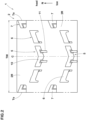
- FIG. 2 is a developed partial view of the tread portion 2 of the pneumatic tire 1.
- the normal state is such that the tire is mounted on a standard wheel rim and inflate to a standard pressure but loaded with no tire load.
- various dimensions, positions and the like of a pneumatic tire refer to those under the normal state of the tire unless otherwise noted.
- the standard wheel rim is a wheel rim officially approved or recommended for the tire by standards organizations, i.e. JATMA (Japan and Asia), T&RA (North America), ETRTO (Europe), TRAA (Australia), STRO (Scandinavia), ALAPA (Latin America), ITTAC (India) and the like which are effective in the area where the tire is manufactured, sold or used.
- the standard pressure is the air pressure for the tire specified by the same organization in the Air-pressure/Maximum-load Table or similar list, i.e. the "maximum air pressure” in JATMA, the “Inflation Pressure” in ETRTO, the maximum pressure given in the "Tire Load Limits at various cold Inflation Pressures” table in TRA or the like.
- the radially outer surface of the tread portion 2 is curved in an arc shape which is convex toward the outside in the tire radial direction.
- the tread portion 2 is provided with a directional tread pattern for which the tire rotation direction N is specified.
- the tread portion 2 in the present embodiment is provided with a plurality of crown blocks 5 disposed on the tire equator C.
- Each of the crown blocks 5 comprises a crown block main portion 10 and crown fin portions 11.
- the crown block main portion 10 is formed in a v-shape bent convexly toward a tire circumferential direction opposite to the intended tire rotation direction N, namely, toward the toe side in the intended tire rotation direction N.
- the crown fin portions 11 protrude from the crown block main portion 10 toward the toe side in the intended tire rotation direction N.
- the crown fin portions 11 suppress the crown block main portion 10 from collapsing toward the circumferential direction opposite to the intended tire rotation direction N, and the crown block main portion 10 exerts an essential mud digging power to improve the traction performance of the tire.
- the crown block main portion 10 can exert its edge effect at a high level.
- the tread portion 2 in this example is further provided with middle blocks 6 located axially outside the crown blocks 5, and shoulder blocks 7 located axially outside the middle blocks 6.
- one middle block 6 is disposed adjacently. But, the blocks 5 to 7 are separated from each other by a tread base portion 2R.
- FIG. 3 is an enlarged top view of the crown block 5. As shown in FIG. 3 , the crown block main portion 10 has
- the crown block main portion 10 has a block side wall surface 8 extending from the heel-side block edge 13, the toe-side block edge 14 and the circumferential edges 15 to the above-mentioned tread base portion 2R.
- Each of the circumferential edges 15 in this example extends straight and substantially parallel to the tire circumferential direction.
- the expression “substantially parallel to the tire circumferential direction” means that the inclination angle with respect to the tire circumferential direction is in a range from 0 to 10 degrees.
- each of the heel-side block edge 13 and the toe-side block edge 14 is inclined to the heel side in the intended tire rotation direction N toward both outer sides in a block width direction in parallel to the tire axial direction from the center in the block width direction.
- the heel-side block edge 13 has the toe-side end 13e positioned on the most toe-side in the intended tire rotation direction N.
- the toe-side block edge 14 has the toe-side end 14e positioned on the most toe-side in the intended tire rotation direction N.
- the toe-side ends 13e and 14e in the present embodiment are located on the tire equator c.
- the angle ⁇ 1 of the heel-side block edge 13 is preferably not less than 10 degrees, more preferably not less than 15 degrees, but preferably not more than 45 degrees, more preferably not more than 35 degrees with respect to the tire axial direction.
- angle ⁇ 1 is that of a straight line drawn between the toe-side end 13e and the intersecting point between the heel-side block edge 13 and one of the circumferential edges 15.
- the heel-side block edge 13 is inclined with respect to the tire axial direction continuously from each circumferential edge 15 to the toe-side end 13e to the same direction toward the toe side in the intended tire rotation direction N.
- the heel-side block edge 13 comprises
- the first intermediate portions 13c are inclined at a larger angle with respect to the tire axial direction than the first outer portions 13a and the first inner portion 13b.
- each of the first outer portions 13a and the first intermediate portions 13c extends in a straight line, and the first inner portion 13b extends in a v shape.
- the difference ( ⁇ 1c- ⁇ 1a) between the angle ⁇ 1a of the first outer portion 13a and the angle ⁇ 1c of the first intermediate portion 13c, each with respect to the tire axial direction, is preferably not less than 10 degrees, more preferably not less than 15 degrees, but preferably not more than 35 degrees, more preferably not more than 30 degrees.
- the difference ( ⁇ 1c- ⁇ 1b) between the angle ⁇ 1b of the first inner portion 13b and the angle ⁇ 1c of the first intermediate portion 13c, each with respect to the tire axial direction, is preferably not less than 10 degrees, more preferably not less than 15 degrees, but preferably not more than 35 degrees, more preferably not more than 30 degrees.
- the toe-side block edge 14 comprises an inner edge portion 14A and two outer edge portions 14B.
- the inner edge portion 14A extends axially inwardly from connection portions K between the crown block main portion 10 and the two crown fin portions 11.
- the two outer edge portions 14B respectively extend axially outwardly from connection portions ⁇ between the crown block main portion 10 and the two crown fin portions 11.
- the inner edge portion 14A includes the toe-side end 14e.
- the inner edge portion 14A extends in a v shape.
- the outer edge portions 14B respectively extend to the circumferential edges 15.
- each of the outer edge portions 14B extends in a straight line.
- each of the two crown fin portions 11 is formed in a parallel quadrilateral shape in the top view of the block. As shown in FIG. 4 , the crown fin portions 11 in this example each have
- the outer edge 11e and the inner edge 11i in this example extend in parallel with the tire circumferential direction.
- the first edge 11a and the second edge 11b in this example extend in parallel with the adjacent outer edge portion 14B.
- the inner edge 11i, the outer edge 11e, the heel-side edge 11a and the toe-side edge 11b define the radially outer surface 11A of the crown fin portion 11.
- the radially outer surface 11A is located radially outside the ground contacting top surface 12 of the crown block main portion 10.
- the radially outer surface 11A may be located at the same radial position as the ground contacting top surface 12 of the crown block main portion 10.
- the outer edges 11e of the two crown fin portions 11 are located inside in the block width direction than the both ends 10e in the tire axial direction of the crown block main portion 10. As a result, the deformation of the crown fin portions 11 is ensured, and the effect of ejecting mud is enhanced.
- the distance La in the tire axial direction between the two crown fin portions 11 is preferably set in a range of not less than 30%, more preferably not less than 35%, but not more than 50%, more preferably not more than 45% of the width W1 in the tire axial direction of the crown block main portion 10 as shown in FIG. 3 .
- the distance La is not more than 50% of the width W1
- the collapse of the crown block main portion 10 can be effectively suppressed.
- the distance Lb in the tire axial direction between the outer edge 11e of each crown fin portion 11 and the adjacent axial end 10e of the crown block main portion 10 is preferably not less than 15%, more preferably not less than 20%, but preferably not more than 35%, more preferably not more than 30% of the width W1 in the tire axial direction of the crown block main portion 10,
- the width w2 in the tire axial direction of each crown fin portion 11 is preferably not less than 5%, more preferably not less than 10%, but preferably not more than 20%, more preferably not more than 15% of the width W1 in the tire axial direction of the crown block main portion 10.
- width w2 is not less than 5% of the width W1, it is possible to effectively suppress the collapse of the crown block main portion 10.
- width W2 is not more than 20% of the width W1
- excessive increase in the rigidity of the crown fin portion 11 is suppressed, and the effect of ejecting mud is maintained.
- the protruding length Lc (shown in FIG. 3 ) in the tire circumferential direction of each crown fin portion 11 from the crown block main portion 10 is preferably not less than 50%, more preferably not less than 60% of the length L1 (shown in FIG. 3 ) in the tire circumferential direction of the crown block main portion 10.
- the protruding length Lc is preferably not more than 150%, more preferably not more than 110% of the length L1.
- connection portion K between the crown block main portion 10 and each crown fin portion 11 is provided with a shallow groove 18 for promoting deformation of a part of the crown fin portion 11 on the connection portion K side.
- shallow grooves 18 help to smoothly eject the mud clogged between the crown fin portions 11.
- the shallow groove 18 extends from the inner edge portion 14A to the outer edge portion 14B so as to surround the above-said part of the crown fin portion 11 on the connection portion K side.
- the shallow groove 18 extends along a part of the outer edge 11e, the heel-side edge 11a, and a part of the inner edge 11i.
- the shallow groove 18 extends in a u shape convex toward the heel side in the intended tire rotation direction N.
- the shallow groove 18 allows the crown fin portion 11 to deform as if independent from the crown block main portion 10, therefore, the traction performance on rough terrain is further improved.
- FIG. 6 is a cross-sectional view taken along line A-A of FIG. 5 .
- the groove depth d1 of the shallow groove 18 from the ground contacting top surface 12 of the crown block main portion 10 is preferably not less than 5%, more preferably not less than 10%, but preferably not more than 25%, more preferably not more than 20% of the radial height H1 of the crown block 5 from the tread base portion 2R to the ground contacting top surface 12.
- the width W3 of the shallow groove 18 is preferably not less than 2%, more preferably not less than 5%, but preferably not more than 15%, more preferably not more than 10% of the width W1 in the tire axial direction of the crown block main portion 10.
- the distance Ld measured parallel to the tire circumferential direction from the heel-side end 18e of the shallow groove 18 to the toe-side block edge 14 is not more than 60% of the length L1 in the tire circumferential direction of the crown block main portion 10.
- the width W1 in the tire axial direction of the crown block main portion 10 is preferably not less than 20%, more preferably not less than 25%, but preferably not more than 40%, more preferably not more than 35% of the developed tread width TW.
- the developed tread width TW is the distance measured in the tire axial direction between the tread edges Te when the tread portion 2 is unfolded flat.
- FIG. 7 is a cross-sectional view taken along line B-B of FIG. 5 .
- the block side wall surface 8 of the crown block main portion 10 includes
- the first side wall surface 16 comprises a radially outer portion 16a and a radially inner portion 16b.
- the radially outer portion 16a extends substantially straight, radially inwardly from the heel-side block edge 13, while inclining toward the toe side in the intended tire rotation direction N with respect to a straight line drawn normally to the ground contacting top surface 12 from the heel-side block edge 13.
- the expression “extend substantially straight” means to extend parallel to not only a perfect straight line having an infinite radius of curvature but also an arc line having a radius of curvature of at least 200 mm.
- the radially inner portion 16b extends from the radially outer portion 16a to the tread base portion 2R while curving in an arc shape in the cross-sectional view.
- Such first side wall surface 16 can deeply dig into mud or soft ground.
- the radially inner portion 16b is formed with a single radius of curvature in the present embodiment.
- Such radially inner portion 16b relaxes the stress concentration acting on the radially inner portion 16b, and further improve the traction performance.
- the radially inner portion 16b may be formed by a multi-radius curve.
- the second side wall surface 17 in the present embodiment comprises a first portion 17a, a second portion 17b, and a third portion 17c.
- the first portion 17a extends radially inwardly from the toe-side block edge 14.
- the second portion 17b extends radially inwardly from the first portion 17a and is inclined more gently than the first portion 17a.
- the third portion 17c extends radially inwardly from the second portion 17b to the tread base portion 2R.
- each of the first portion 17a and the second portion 17b extends linearly in the cross-sectional view.
- the third portion 17c is curved in an arc shape.
- the third portion 17c is formed in an arc shape concave toward the heel side in the intended tire rotation direction N.
- FIG. 8 shows the vicinity of the middle block 6.
- each middle block 6 is inclined to the heel side in the intended tire rotation direction N, while extending from the inside to the outside in the tire axial direction, and comprises a middle block main portion 20 having a parallelogram shape, and a middle fin portion 21 protruding toward the toe side in the intended tire rotation direction N from the middle block main portion 20.
- the middle block main portion 20 has a ground contacting top surface 22, a heel-side middle edge 23, a toe-side middle edge 24, and a pair of circumferential middle edges 25 extending from both ends of the heel-side middle edge 23, respectively, toward the toe side in the intended tire rotation direction N.
- the pair of circumferential middle edges 25 is an axially inner circumferential middle edge 25a adjacent one of the crown blocks 5, and an axially outer circumferential middle edge 25b adjacent to one of the shoulder blocks 7.
- the circumferential middle edges 25 in this example extend linearly.
- the middle block main portion 20 is provided with the two middle fin portions 21.
- the two middle fin portions 21 are identical.
- the axially outer middle fin portion 21A is directly connected to the middle block main portion 20.
- the axially outer edge 26 of the axially outer middle fin portion 21A and the axially outer circumferential middle edge 25b are formed by a single straight line.
- the axially inner middle fin portion 21B is connected to the middle block main portion 20, and along the junction between them, a middle shallow groove 30 is formed.
- the axially inner edge 27 of the axially inner middle fin portion 21B and the axially inner circumferential middle edge 25a extend in line across the middle shallow groove 30.
- the middle shallow groove 30's edge 30a positioned on the heel side in the intended tire rotation direction N and extending in the longitudinal direction forms the above-mentioned toe-side middle edge 24 in this example.
- the groove width w4 of the middle shallow groove 30 is preferably not less than 80%, more preferably not less than 90%, but preferably not more than 125%, more preferably not more than 110% of the groove width W3 ( FIG. 5 ) of the shallow groove 18 of the crown block 5.
- the groove depth of the middle shallow groove 30 (not shown) is preferably not less than 5%, more preferably not less than 10%, but preferably not more than 20%, more preferably not more than 15% of the block height of the middle block main portion 20 measured from the ground contacting top surface to the tread base portion 2R.
- the axial width W5 ( FIG. 8 ) of the middle block main portion 20 is preferably not less than 5%, more preferably not less than 10%, but preferably not more than 25%, more preferably not more than 20% of the developed tread width TW.
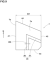
- FIG. 9 is a top view of one of the shoulder blocks 7.
- the shoulder block 7 in this example is formed in a generally quadrilateral shape, more specifically trapezoidal shape in its top view.
- the ground contacting top surface 7a of the shoulder block 7 has an axially outer edge 41, an axially inner edge 42, a toe-side edge 43, and a heel-side edge 44.
- the axially outer edge 41 extends in the tire circumferential direction, and in this example, forms a part of the tread edge Te.
- the axially inner edge 42 extends in the tire circumferential direction in this example.
- the toe-side edge 43 extends in parallel with the tire axial direction from the axially outer edge 41 toward the axially inner edge 42 in this example.
- the heel-side edge 44 extends from the axially inner edge 42 to the axially outer edge 41 while inclining with respect to the tire axial direction, for example, toward the intended tire rotation direction N in this example.
- Each of the shoulder blocks 7 is provided with a shoulder shallow groove 45 in this example.
- the shoulder shallow groove 45 extends in a V shape in the top view of the shoulder block 7.
- Such shoulder shallow groove 45 promotes the deformation of the shoulder block 7, and helps to eject the mud clogged between the shoulder block 7 and the adjacent middle block 6.
- the shoulder shallow groove 45 is composed of a circumferential portion 46 extending in the tire circumferential direction, and an axial portion 47 extending in the tire axial direction.
- the circumferential portion 46 extends at an angle of not more than 45 degrees with respect to the tire circumferential direction.
- the axial portion 47 extends at an angle of more than 45 degrees with respect to the tire circumferential direction.
- the circumferential portion 46 extends in parallel with the tire circumferential direction from the toe-side edge 43 toward the heel side in the intended tire rotation direction N, and ends within the shoulder block 7.
- the axial portion 47 extends from the axially inner edge 42 toward the outside in the tire axial direction, and is connected to the end of the circumferential portion 46.
- the axial portion 47 extends in parallel with the heel-side edge 44.
- Such shoulder shallow groove 45 further promotes deformation of the shoulder block 7.
- the groove width W6 of the shoulder shallow groove 45 is preferably not less than 5%, more preferably not less than 10%, but preferably not more than 25%, more preferably not more than 20% of the axial width w7 ( FIG. 9 ) of the shoulder block 7.
- the groove depth of the shoulder shallow groove 45 is preferably not less than 5%, more preferably not less than 10%, but preferably not more than 20%, more preferably not more than 15% of the block height of the shoulder block 7 measured from the ground contacting top surface to the tread base portion 2R.
- the axial width W7 of the shoulder block 7 is preferably not less than 5%, more preferably not less than 7%, but preferably not more than 20%, more preferably not more than 15% of the developed tread width TW.
- the tread rubber 2G ( FIG. 1 ) by which the above-mentioned blocks 5 to 7 are formed has a rubber hardness of not less than 70 degrees, and not more than 90 degrees.
- the rubber hardness means the durometer A hardness measured at a temperature of 23 degrees c according to the Japanese Industrial Standard (JIS) K6253.
- pneumatic tires for a rear wheel of a motorcycle for running on rough terrain were experimentally manufactured as test tires (working example tires Ex.1-Ex.6 and Comprehensive example tire Ref.1). Specifications of the test tires are shown in Table 1.
- test tires were tested for the traction performance, braking performance and overall performance, using a 450cc motorcycle for motocross competition having the following rim sizes and tire sizes.
- the test method was as follows.
- the "traction performance” is an evaluation of the traction force at the time of accelerating during straight running and cornering, made by the test rider.
- the "brake performance” is an evaluation of the braking force at the time of braking during straight running and cornering, made by the test rider.
- the "overall performance” is an evaluation of the running stability at the time of accelerating and braking during straight running and cornering, made by the test rider.
- the present invention is as follows:
Landscapes
- Engineering & Computer Science (AREA)
- Mechanical Engineering (AREA)
- Tires In General (AREA)
Abstract
Description
- The present invention relates to a tire for rough terrain.
- The following
Patent Document 1 discloses a tire for running on rough terrain in which the tread portion is provided with crown blocks. The crown block comprises a crown block main portion, and three crown fin portions protruding in the tire circumferential direction from the crown block main portion. Such crown fin portions are explained as being useful for enhancing traction performance.
Patent Document 1:Japanese Patent Application Publication No. 2021-084554 - when traveling on muddy ground or road with the above-mentioned tire, the mud tends to be clogged between the crown fin portions, and the clogged mud is difficult to be ejected, therefore, the traction tends to decrease.
- The present invention was made in view of the above circumstances, and
a primary object of the present invention is to provide a tire for running on rough terrain which is improved in traction performance on rough terrain. - According to the present invention, a tire for running on rough terrain for which an intended tire rotational direction is specified, comprises a tread portion provided with crown blocks disposed on the tire equator,
wherein
each of the crown blocks comprises - a v-shaped crown block main portion which bends convexly toward a circumferential direction opposite to the intended tire rotation direction, and
- crown fin portions projecting from the crown block main portion toward the above-said circumferential direction opposite to the intended tire rotation direction, and
- the number of the crown fin portions is two per one crown block.
- In the tire according to the present invention, therefore, the traction performance when traveling on rough terrain can be improved by the crown blocks having the above described configuration.
-
-
FIG. 1 is a tire meridian cross-sectional view of a tire as an embodiment of the present invention. -
FIG. 2 is a developed plan view of a part of the tread portion ofFIG. 1 -
FIGS. 3 ,4 and5 shows the same top view of a crown block shown inFIG. 2 but differently provided with reference numerals. -
FIG. 6 is a cross-sectional view taken along line A-A ofFIG. 5 . -
FIG. 7 is a cross-sectional view taken along line B-B ofFIG. 5 . -
FIG. 8 is a top view of a middle block shown inFIG. 2 . -
FIG. 9 is a top view of a shoulder block shown inFIG. 2 . - The present invention is suitably applied to a tire for motorcycles, but may be applied to tires for passenger cars, heavy duty vehicles and the like.
- Further, the present invention can be applied to not only pneumatic tires but also non-pneumatic tires so called airless tires.
- Hereinafter, an embodiment of the present invention will be described in detail with reference to the accompanying drawings.
-
FIG. 1 is a cross-sectional partial view of apneumatic tire 1 for running on rough terrain as an embodiment of the present invention. - This cross-sectional view is a tire meridian cross-sectional view including the tire rotation axis (not shown) under a normal state of the
pneumatic tire 1. -
FIG. 2 is a developed partial view of thetread portion 2 of thepneumatic tire 1. - In the case of a pneumatic tire, the normal state is such that the tire is mounted on a standard wheel rim and inflate to a standard pressure but loaded with no tire load. In this application including specification and claims, various dimensions, positions and the like of a pneumatic tire refer to those under the normal state of the tire unless otherwise noted. The standard wheel rim is a wheel rim officially approved or recommended for the tire by standards organizations, i.e. JATMA (Japan and Asia), T&RA (North America), ETRTO (Europe), TRAA (Australia), STRO (Scandinavia), ALAPA (Latin America), ITTAC (India) and the like which are effective in the area where the tire is manufactured, sold or used.
- The standard pressure is the air pressure for the tire specified by the same organization in the Air-pressure/Maximum-load Table or similar list, i.e. the "maximum air pressure" in JATMA, the "Inflation Pressure" in ETRTO, the maximum pressure given in the "Tire Load Limits at various cold Inflation Pressures" table in TRA or the like.
- In the tire meridian cross-section of the
tire 1, the radially outer surface of thetread portion 2 is curved in an arc shape which is convex toward the outside in the tire radial direction. - The
tread portion 2 is provided with a directional tread pattern for which the tire rotation direction N is specified. - The
tread portion 2 in the present embodiment is provided with a plurality ofcrown blocks 5 disposed on the tire equator C. - Each of the
crown blocks 5 comprises a crown blockmain portion 10 and crownfin portions 11. - The crown block
main portion 10 is formed in a v-shape bent convexly toward a tire circumferential direction opposite to the intended tire rotation direction N, namely, toward the toe side in the intended tire rotation direction N. - The crown
fin portions 11 protrude from the crown blockmain portion 10 toward the toe side in the intended tire rotation direction N. - In
such crown block 5, the crownfin portions 11 suppress the crown blockmain portion 10 from collapsing toward the circumferential direction opposite to the intended tire rotation direction N, and the crown blockmain portion 10 exerts an essential mud digging power to improve the traction performance of the tire. - For each of the
crown blocks 5, only two crownfin portions 11 are formed. Thereby, the region where mud is easily clogged, that is, the region between the crownfin portions 11 becomes one place for eachcrown block 5, and the clogging of mud is reduced. As a result, the crown blockmain portion 10 can exert its edge effect at a high level. - The
tread portion 2 in this example is further provided withmiddle blocks 6 located axially outside thecrown blocks 5, andshoulder blocks 7 located axially outside themiddle blocks 6. - In the present embodiment, as shown in
FIG. 4 , on each side in the tire axial direction of each of thecrown blocks 5, onemiddle block 6 is disposed adjacently. But, theblocks 5 to 7 are separated from each other by atread base portion 2R. -
FIG. 3 is an enlarged top view of thecrown block 5. As shown inFIG. 3 , the crown blockmain portion 10 has - a ground contacting
top surface 12, - a heel-
side block edge 13, namely, the edge of the ground contactingtop surface 12 on the heel side in the intended tire rotation direction N, - a toe-
side block edge 14, namely, the edge of the ground contactingtop surface 12 on the toe side in the intended tire rotation direction N, and - a pair of
circumferential edges 15 extending in the tire circumferential direction from the axially outer ends of the heel-side block edge 13 to the axially outer ends of the toe-side block edge 14. - Further, the crown block
main portion 10 has a blockside wall surface 8 extending from the heel-side block edge 13, the toe-side block edge 14 and thecircumferential edges 15 to the above-mentionedtread base portion 2R. - Each of the
circumferential edges 15 in this example extends straight and substantially parallel to the tire circumferential direction. - Here, the expression "substantially parallel to the tire circumferential direction" means that the inclination angle with respect to the tire circumferential direction is in a range from 0 to 10 degrees.
- In the present embodiment, each of the heel-
side block edge 13 and the toe-side block edge 14 is inclined to the heel side in the intended tire rotation direction N toward both outer sides in a block width direction in parallel to the tire axial direction from the center in the block width direction. - The heel-
side block edge 13 has the toe-side end 13e positioned on the most toe-side in the intended tire rotation direction N. The toe-side block edge 14 has the toe-side end 14e positioned on the most toe-side in the intended tire rotation direction N. The toe-side ends - The angle θ1 of the heel-
side block edge 13 is preferably not less than 10 degrees, more preferably not less than 15 degrees, but preferably not more than 45 degrees, more preferably not more than 35 degrees with respect to the tire axial direction. - Here, the angle θ1 is that of a straight line drawn between the toe-
side end 13e and the intersecting point between the heel-side block edge 13 and one of the circumferential edges 15. - As shown in
FIG. 4 , the heel-side block edge 13 is inclined with respect to the tire axial direction continuously from eachcircumferential edge 15 to the toe-side end 13e to the same direction toward the toe side in the intended tire rotation direction N. - The heel-
side block edge 13 comprises - two first
outer portions 13a extending from the respectivecircumferential edges 15, - a first
inner portion 13b including the toe-side end 13e, and two firstintermediate portions 13c connecting between the firstinner portion 13b and the two firstouter portion 13a. - The first
intermediate portions 13c are inclined at a larger angle with respect to the tire axial direction than the firstouter portions 13a and the firstinner portion 13b. - In the present embodiment, each of the first
outer portions 13a and the firstintermediate portions 13c extends in a straight line, and the firstinner portion 13b extends in a v shape. - The difference (θ1c-θ1a) between the angle θ1a of the first
outer portion 13a and the angle θ1c of the firstintermediate portion 13c, each with respect to the tire axial direction, is preferably not less than 10 degrees, more preferably not less than 15 degrees, but preferably not more than 35 degrees, more preferably not more than 30 degrees. - The difference (θ1c-θ1b) between the angle θ1b of the first
inner portion 13b and the angle θ1c of the firstintermediate portion 13c, each with respect to the tire axial direction, is preferably not less than 10 degrees, more preferably not less than 15 degrees, but preferably not more than 35 degrees, more preferably not more than 30 degrees. - The toe-
side block edge 14 comprises aninner edge portion 14A and twoouter edge portions 14B. - The
inner edge portion 14A extends axially inwardly from connection portions K between the crown blockmain portion 10 and the twocrown fin portions 11. - The two
outer edge portions 14B respectively extend axially outwardly from connection portions κ between the crown blockmain portion 10 and the twocrown fin portions 11. - The
inner edge portion 14A includes the toe-side end 14e. - The
inner edge portion 14A extends in a v shape. - In the present embodiment, the
outer edge portions 14B respectively extend to the circumferential edges 15. - In the present embodiment, each of the
outer edge portions 14B extends in a straight line. - In the present embodiment, each of the two
crown fin portions 11 is formed in a parallel quadrilateral shape in the top view of the block. As shown inFIG. 4 , thecrown fin portions 11 in this example each have - an
outer edge 11e in the block width direction, - an
inner edge 11i in the block width direction, - a heel-
side edge 11a on the heel side in the intended tire rotation direction N, and - a toe-
side edge 11b on the toe side in the intended tire rotation direction N. - The
outer edge 11e and theinner edge 11i in this example extend in parallel with the tire circumferential direction. - The
first edge 11a and thesecond edge 11b in this example extend in parallel with the adjacentouter edge portion 14B. Theinner edge 11i, theouter edge 11e, the heel-side edge 11a and the toe-side edge 11b define the radiallyouter surface 11A of thecrown fin portion 11. - As shown in
FIG. 6 , in the present embodiment, the radiallyouter surface 11A is located radially outside the ground contactingtop surface 12 of the crown blockmain portion 10. However, the radiallyouter surface 11A may be located at the same radial position as the ground contactingtop surface 12 of the crown blockmain portion 10. - The
outer edges 11e of the twocrown fin portions 11 are located inside in the block width direction than the both ends 10e in the tire axial direction of the crown blockmain portion 10. As a result, the deformation of thecrown fin portions 11 is ensured, and the effect of ejecting mud is enhanced. - The distance La in the tire axial direction between the two
crown fin portions 11 is preferably set in a range of not less than 30%, more preferably not less than 35%, but not more than 50%, more preferably not more than 45% of the width W1 in the tire axial direction of the crown blockmain portion 10 as shown inFIG. 3 . - Since the distance La is not less than 30% of the width W1, mud ejection becomes smooth.
- Since the distance La is not more than 50% of the width W1, the collapse of the crown block
main portion 10 can be effectively suppressed. - The distance Lb in the tire axial direction between the
outer edge 11e of eachcrown fin portion 11 and the adjacentaxial end 10e of the crown blockmain portion 10 is preferably not less than 15%, more preferably not less than 20%, but preferably not more than 35%, more preferably not more than 30% of the width W1 in the tire axial direction of the crown blockmain portion 10, - As a result, the deformation of the
crown fin portions 11 is ensured, and the effect of ejecting mud is enhanced. - The width w2 in the tire axial direction of each
crown fin portion 11 is preferably not less than 5%, more preferably not less than 10%, but preferably not more than 20%, more preferably not more than 15% of the width W1 in the tire axial direction of the crown blockmain portion 10. - Since the width w2 is not less than 5% of the width W1, it is possible to effectively suppress the collapse of the crown block
main portion 10. - Since the width W2 is not more than 20% of the width W1, excessive increase in the rigidity of the
crown fin portion 11 is suppressed, and the effect of ejecting mud is maintained. - In order to prevent the crown block
main portion 10 from collapsing, the protruding length Lc (shown inFIG. 3 ) in the tire circumferential direction of eachcrown fin portion 11 from the crown blockmain portion 10 is preferably not less than 50%, more preferably not less than 60% of the length L1 (shown inFIG. 3 ) in the tire circumferential direction of the crown blockmain portion 10. - However, if the protruding length Lc is excessively large, the effect of ejecting mud may deteriorate, therefore, the protruding length Lc is preferably not more than 150%, more preferably not more than 110% of the length L1.
- As shown in
FIG. 5 , the connection portion K between the crown blockmain portion 10 and eachcrown fin portion 11 is provided with ashallow groove 18 for promoting deformation of a part of thecrown fin portion 11 on the connection portion K side. Thus, suchshallow grooves 18 help to smoothly eject the mud clogged between thecrown fin portions 11. - The
shallow groove 18 extends from theinner edge portion 14A to theouter edge portion 14B so as to surround the above-said part of thecrown fin portion 11 on the connection portion K side. - The
shallow groove 18 extends along a part of theouter edge 11e, the heel-side edge 11a, and a part of theinner edge 11i. - Thus, the
shallow groove 18 extends in a u shape convex toward the heel side in the intended tire rotation direction N. - The
shallow groove 18 allows thecrown fin portion 11 to deform as if independent from the crown blockmain portion 10, therefore, the traction performance on rough terrain is further improved. -
FIG. 6 is a cross-sectional view taken along line A-A ofFIG. 5 . - As shown in
FIG. 6 , the groove depth d1 of theshallow groove 18 from the ground contactingtop surface 12 of the crown blockmain portion 10 is preferably not less than 5%, more preferably not less than 10%, but preferably not more than 25%, more preferably not more than 20% of the radial height H1 of thecrown block 5 from thetread base portion 2R to the ground contactingtop surface 12. - Further, as shown in
FIG. 5 , the width W3 of theshallow groove 18 is preferably not less than 2%, more preferably not less than 5%, but preferably not more than 15%, more preferably not more than 10% of the width W1 in the tire axial direction of the crown blockmain portion 10. - As a result, the above-mentioned action is effectively exhibited, and the
crown fin portions 11 and the crown blockmain portion 10 secure rigidity and generate a larger shearing force against mud and soil. - It is preferable that the distance Ld measured parallel to the tire circumferential direction from the heel-
side end 18e of theshallow groove 18 to the toe-side block edge 14 is not more than 60% of the length L1 in the tire circumferential direction of the crown blockmain portion 10. - Thereby, the rigidity in the tire circumferential direction of the crown block
main portion 10 is maintained. - As a result, the effect of suppressing the collapse of the
crown block 5 when contacting with the ground is highly exhibited. - The width W1 in the tire axial direction of the crown block
main portion 10 is preferably not less than 20%, more preferably not less than 25%, but preferably not more than 40%, more preferably not more than 35% of the developed tread width TW. - As shown in
FIG. 2 , the developed tread width TW is the distance measured in the tire axial direction between the tread edges Te when thetread portion 2 is unfolded flat. -
FIG. 7 is a cross-sectional view taken along line B-B ofFIG. 5 . As shown inFIG. 7 , the blockside wall surface 8 of the crown blockmain portion 10 includes - a first
side wall surface 16 extending radially inwardly from the heel-side block edge 13, and - a second
side wall surface 17 extending radially inwardly from the toe-side block edge 14. - The first
side wall surface 16 comprises a radiallyouter portion 16a and a radiallyinner portion 16b. - In the cross-sectional view, the radially
outer portion 16a extends substantially straight, radially inwardly from the heel-side block edge 13, while inclining toward the toe side in the intended tire rotation direction N with respect to a straight line drawn normally to the ground contactingtop surface 12 from the heel-side block edge 13. - Here, the expression "extend substantially straight" means to extend parallel to not only a perfect straight line having an infinite radius of curvature but also an arc line having a radius of curvature of at least 200 mm.
- The radially
inner portion 16b extends from the radiallyouter portion 16a to thetread base portion 2R while curving in an arc shape in the cross-sectional view. Such firstside wall surface 16 can deeply dig into mud or soft ground. - The radially
inner portion 16b is formed with a single radius of curvature in the present embodiment. - Such radially
inner portion 16b relaxes the stress concentration acting on the radiallyinner portion 16b, and further improve the traction performance. However, the radiallyinner portion 16b may be formed by a multi-radius curve. - The second
side wall surface 17 in the present embodiment comprises afirst portion 17a, asecond portion 17b, and athird portion 17c. - The
first portion 17a extends radially inwardly from the toe-side block edge 14. - The
second portion 17b extends radially inwardly from thefirst portion 17a and is inclined more gently than thefirst portion 17a. - The
third portion 17c extends radially inwardly from thesecond portion 17b to thetread base portion 2R. - In the present embodiment, each of the
first portion 17a and thesecond portion 17b extends linearly in the cross-sectional view. And thethird portion 17c is curved in an arc shape. - For example, the
third portion 17c is formed in an arc shape concave toward the heel side in the intended tire rotation direction N. -
FIG. 8 shows the vicinity of themiddle block 6. As shown inFIG. 8 , eachmiddle block 6 is inclined to the heel side in the intended tire rotation direction N, while extending from the inside to the outside in the tire axial direction, and comprises a middle blockmain portion 20 having a parallelogram shape, and amiddle fin portion 21 protruding toward the toe side in the intended tire rotation direction N from the middle blockmain portion 20. - The middle block
main portion 20 has a ground contactingtop surface 22, a heel-sidemiddle edge 23, a toe-sidemiddle edge 24, and a pair of circumferentialmiddle edges 25 extending from both ends of the heel-sidemiddle edge 23, respectively, toward the toe side in the intended tire rotation direction N. - The pair of circumferential middle edges 25 is an axially inner circumferential
middle edge 25a adjacent one of the crown blocks 5, and an axially outer circumferentialmiddle edge 25b adjacent to one of the shoulder blocks 7. - The circumferential middle edges 25 in this example extend linearly.
- In the present embodiment, the middle block
main portion 20 is provided with the twomiddle fin portions 21. - The two
middle fin portions 21 are - an axially outer
middle fin portion 21A connected to the axially outer circumferentialmiddle edge 25b, and - an axially inner
middle fin portion 21B located axially inside the axially outermiddle fin portion 21A. - The axially outer
middle fin portion 21A is directly connected to the middle blockmain portion 20. - The axially
outer edge 26 of the axially outermiddle fin portion 21A and the axially outer circumferentialmiddle edge 25b are formed by a single straight line. - The axially inner
middle fin portion 21B is connected to the middle blockmain portion 20, and along the junction between them, a middleshallow groove 30 is formed. - The axially
inner edge 27 of the axially innermiddle fin portion 21B and the axially inner circumferentialmiddle edge 25a extend in line across the middleshallow groove 30. - Since the deformation of the axially inner
middle fin portion 21B is promoted by the middleshallow groove 30, the mud clogged between themiddle fin portions 21 can be smoothly ejected. - The middle
shallow groove 30'sedge 30a positioned on the heel side in the intended tire rotation direction N and extending in the longitudinal direction forms the above-mentioned toe-sidemiddle edge 24 in this example. - The groove width w4 of the middle
shallow groove 30 is preferably not less than 80%, more preferably not less than 90%, but preferably not more than 125%, more preferably not more than 110% of the groove width W3 (FIG. 5 ) of theshallow groove 18 of thecrown block 5. - The groove depth of the middle shallow groove 30 (not shown) is preferably not less than 5%, more preferably not less than 10%, but preferably not more than 20%, more preferably not more than 15% of the block height of the middle block
main portion 20 measured from the ground contacting top surface to thetread base portion 2R. - The axial width W5 (
FIG. 8 ) of the middle blockmain portion 20 is preferably not less than 5%, more preferably not less than 10%, but preferably not more than 25%, more preferably not more than 20% of the developed tread width TW. -
FIG. 9 is a top view of one of the shoulder blocks 7. As shown, theshoulder block 7 in this example is formed in a generally quadrilateral shape, more specifically trapezoidal shape in its top view. - The ground contacting
top surface 7a of theshoulder block 7 has an axiallyouter edge 41, an axiallyinner edge 42, a toe-side edge 43, and a heel-side edge 44. - The axially
outer edge 41 extends in the tire circumferential direction, and in this example, forms a part of the tread edge Te. - The axially
inner edge 42 extends in the tire circumferential direction in this example. - The toe-
side edge 43 extends in parallel with the tire axial direction from the axiallyouter edge 41 toward the axiallyinner edge 42 in this example. - The heel-
side edge 44 extends from the axiallyinner edge 42 to the axiallyouter edge 41 while inclining with respect to the tire axial direction, for example, toward the intended tire rotation direction N in this example. - Each of the shoulder blocks 7 is provided with a shoulder
shallow groove 45 in this example. - As shown in
FIG. 9 , the shouldershallow groove 45 extends in a V shape in the top view of theshoulder block 7. - Such shoulder
shallow groove 45 promotes the deformation of theshoulder block 7, and helps to eject the mud clogged between theshoulder block 7 and the adjacentmiddle block 6. - The shoulder
shallow groove 45 is composed of acircumferential portion 46 extending in the tire circumferential direction, and anaxial portion 47 extending in the tire axial direction. - The
circumferential portion 46 extends at an angle of not more than 45 degrees with respect to the tire circumferential direction. - The
axial portion 47 extends at an angle of more than 45 degrees with respect to the tire circumferential direction. - In this example, the
circumferential portion 46 extends in parallel with the tire circumferential direction from the toe-side edge 43 toward the heel side in the intended tire rotation direction N, and ends within theshoulder block 7. - In this example, the
axial portion 47 extends from the axiallyinner edge 42 toward the outside in the tire axial direction, and is connected to the end of thecircumferential portion 46. Theaxial portion 47 extends in parallel with the heel-side edge 44. - Such shoulder
shallow groove 45 further promotes deformation of theshoulder block 7. - The groove width W6 of the shoulder
shallow groove 45 is preferably not less than 5%, more preferably not less than 10%, but preferably not more than 25%, more preferably not more than 20% of the axial width w7 (FIG. 9 ) of theshoulder block 7. - The groove depth of the shoulder
shallow groove 45 is preferably not less than 5%, more preferably not less than 10%, but preferably not more than 20%, more preferably not more than 15% of the block height of theshoulder block 7 measured from the ground contacting top surface to thetread base portion 2R. - The axial width W7 of the
shoulder block 7 is preferably not less than 5%, more preferably not less than 7%, but preferably not more than 20%, more preferably not more than 15% of the developed tread width TW. - It is preferable that the
tread rubber 2G (FIG. 1 ) by which the above-mentionedblocks 5 to 7 are formed has a rubber hardness of not less than 70 degrees, and not more than 90 degrees. - Here, the rubber hardness means the durometer A hardness measured at a temperature of 23 degrees c according to the Japanese Industrial Standard (JIS) K6253.
- while detailed description has been made of a preferable embodiment of the present invention, the present invention can be embodied in various forms without being limited to the illustrated embodiment.
- Based on the tread pattern shown in
FIG. 2 , pneumatic tires for a rear wheel of a motorcycle for running on rough terrain were experimentally manufactured as test tires (working example tires Ex.1-Ex.6 and Comprehensive example tire Ref.1). Specifications of the test tires are shown in Table 1. - The test tires were tested for the traction performance, braking performance and overall performance, using a 450cc motorcycle for motocross competition having the following rim sizes and tire sizes.
- front wheel rim size: 21x1.60
- rear wheel rim size: 19x2.15
- front tire size: 80/100-21
- rear tire size: 120/80-19
- In the test, the rear tire was changed, but the front tire was not changed and an identical tire was used. (tire pressure: 80 kPa)
- The test method was as follows.
- The traction performance, brake performance and overall performance when the above-mentioned motorcycle was run on rough terrain covered with mud were evaluated by the test rider.
- Here, the "traction performance" is an evaluation of the traction force at the time of accelerating during straight running and cornering, made by the test rider.
- The "brake performance" is an evaluation of the braking force at the time of braking during straight running and cornering, made by the test rider.
- The "overall performance" is an evaluation of the running stability at the time of accelerating and braking during straight running and cornering, made by the test rider.
- The test rider evaluated each performance on a ten-point scale, and the results are shown in Table 1.
Table 1 Tire Ref.1 Ex.1 Ex.2 Ex.3 Ex.4 Ex.5 Ex.6 number of crown fin portions per block 3 2 2 2 2 2 2 angle θ1 (deg.) 15.7 17.4 17.4 17.4 17.4 17.4 17.4 La/W1 (%) 30 20 38 38 38 50 45 W2/W1 (%) 12 8 8 8 8 8 8 Lc/L1 (%) 130 96 96 96 96 96 96 (P)resence/(A)bsence of shallow groove A P A P P P P d1/H1 (%) - 10 - 10 10 10 10 W3/W1 (%) - 3 - 3 3 3 3 Ld/L1 (%) - 38 - 38 38 38 38 tread rubber hardness (deg.) 70 70 70 70 80 70 70 traction performance 4.5 6.5 6 6.5 7 6 6.5 brake performance 4.5 6 6 6.5 7 6 6 overall performance 4.5 6.5 6 6.5 7 6 6.5 - From the test results, it was confirmed that the traction performance and braking performance on rough terrain of the working example tires were improved as compared with the comparative example tire.
- Statement of the present invention
- The present invention is as follows:
- Present Invention 1: A tire for running on rough terrain for which an intended tire rotational direction is specified, and which comprises a tread portion provided with crown blocks disposed on the tire equator, wherein
each of the crown blocks comprises- a V-shaped crown block main portion which bends convexly toward a circumferential direction opposite to the intended tire rotation direction, and
- only two crown fin portions projecting from the crown block main portion toward the above-said circumferential direction opposite to the intended tire rotation direction.
- Present Invention 2: The tire for running on rough terrain according to
Present Invention 1, wherein
each of said only two crown fin portions has an outer edge in a block width direction which is located inside in the block width direction than both axial ends of the crown block main portion. - Present Invention 3: The tire for running on rough terrain according to
Present Invention
the distance in the tire axial direction between said only two crown fin portions is in a range from 30% to 50% of the width in the tire axial direction of the crown block main portion. - Present Invention 4: The tire for running on rough terrain according to
Present Invention
the width in the tire axial direction of each of said only two crown fin portions is in a range from 5% to 20% of the width in the tire axial direction of the crown block main portion. - Present Invention 5: The tire for running on rough terrain according to
Present Invention
the protruding length of each of said only two crown fin portions measured in the tire circumferential direction from the crown block main portion is not less than 50% of the length in the tire circumferential direction of the crown block main portion - Present Invention 6: The tire for running on rough terrain according to
Present Invention
a connection portion κ between the crown block main portion and each of the crown fin portions is provided with a shallow groove for promoting deformation of a part of the crown fin portion on the connection portion side. - Present Invention 7: The tire for running on rough terrain according to
Present Invention 6, wherein- the crown block main portion has a ground contacting top surface and a toe-side block edge,
- the toe-side block edge comprises
- an inner edge portion extending inward in the tire axial direction from the connection portion, and
- an outer edge portion extending outward in the tire axial direction from the connection portion, and
- the shallow groove extends from the inner edge portion to the outer edge portion so as to surround said part of the crown fin portion on the connection portion side.
- Present Invention 8: The tire for running on rough terrain according to
Present Invention
the depth of the shallow groove is in a range from 5% to 25% of the radial height of the crown block main portion. - Present Invention 9: The tire for running on rough terrain according to any one of
Present Inventions 6 to 8, wherein
the width of the shallow groove is in a range from 2% to 15% of the width in the tire axial direction of the crown block main portion. - Present Invention 10: The tire for running on rough terrain according to any one of
Present Inventions 6 to 9, wherein- the crown block main portion has a ground contacting top surface and a toe-side block edge, and
- the distance in the tire circumferential direction between the toe-side block edge and a heel-side end of the shallow groove is not more than 60% of the length in the tire circumferential direction of the crown block main portion.
- Present Invention 11: The tire for running on rough terrain according to any one of
Present Inventions 1 to 10, wherein- the crown block main portion has a heel-side block edge, and
- the angle of the heel-side block edge with respect to the tire axial direction is in a range from 10 to 45 degrees.
-
- 1
- tire for running on rough terrain
- 2
- tread portion
- 5
- crown block
- 10
- crown block main portion
- 11
- crown fin portion
- N
- intended tire rotational direction
Claims (11)
- A tire for running on rough terrain for which an intended tire rotational direction is specified, and which comprises a tread portion provided with crown blocks disposed on the tire equator, wherein
each of the crown blocks comprisesa V-shaped crown block main portion which bends convexly toward a circumferential direction opposite to the intended tire rotation direction, andonly two crown fin portions projecting from the crown block main portion toward the above-said circumferential direction opposite to the intended tire rotation direction. - The tire for running on rough terrain according to claim 1, wherein
each of said only two crown fin portions has an outer edge in a block width direction which is located inside in the block width direction than both axial ends of the crown block main portion. - The tire for running on rough terrain according to claim 1 or 2, wherein
the distance in the tire axial direction between said only two crown fin portions is in a range from 30% to 50% of the width in the tire axial direction of the crown block main portion. - The tire for running on rough terrain according to claim 1, 2 or 3, wherein
the width in the tire axial direction of each of said only two crown fin portions is in a range from 5% to 20% of the width in the tire axial direction of the crown block main portion. - The tire for running on rough terrain according to claim 1, 2, 3 or 4, wherein
the protruding length of each of said only two crown fin portions measured in the tire circumferential direction from the crown block main portion is not less than 50% of the length in the tire circumferential direction of the crown block main portion - The tire for running on rough terrain according to claim 1, 2, 3, 4 or 5, wherein
a connection portion K between the crown block main portion and each of the crown fin portions is provided with a shallow groove for promoting deformation of a part of the crown fin portion on the connection portion side. - The tire for running on rough terrain according to claim 6, whereinthe crown block main portion has a ground contacting top surface and a toe-side block edge,the toe-side block edge comprisesan inner edge portion extending inward in the tire axial direction from the connection portion, andan outer edge portion extending outward in the tire axial direction from the connection portion, andthe shallow groove extends from the inner edge portion to the outer edge portion so as to surround said part of the crown fin portion on the connection portion side.
- The tire for running on rough terrain according to claim 6 or 7, wherein
the depth of the shallow groove is in a range from 5% to 25% of the radial height of the crown block main portion. - The tire for running on rough terrain according to any one of claims 6 to 8, wherein
the width of the shallow groove is in a range from 2% to 15% of the width in the tire axial direction of the crown block main portion. - The tire for running on rough terrain according to any one of claims 6 to 9, whereinthe crown block main portion has a ground contacting top surface and a toe-side block edge, andthe distance in the tire circumferential direction between the toe-side block edge and a heel-side end of the shallow groove is not more than 60% of the length in the tire circumferential direction of the crown block main portion.
- The tire for running on rough terrain according to any one of claims 1 to 10, whereinthe crown block main portion has a heel-side block edge, andthe angle of the heel-side block edge with respect to the tire axial direction is in a range from 10 to 45 degrees.
Applications Claiming Priority (1)
| Application Number | Priority Date | Filing Date | Title |
|---|---|---|---|
| JP2021164884A JP7711544B2 (en) | 2021-10-06 | 2021-10-06 | Off-road tires |
Publications (2)
| Publication Number | Publication Date |
|---|---|
| EP4163129A1 true EP4163129A1 (en) | 2023-04-12 |
| EP4163129B1 EP4163129B1 (en) | 2024-11-13 |
Family
ID=83439138
Family Applications (1)
| Application Number | Title | Priority Date | Filing Date |
|---|---|---|---|
| EP22197209.4A Active EP4163129B1 (en) | 2021-10-06 | 2022-09-22 | Tire for rough terrain |
Country Status (4)
| Country | Link |
|---|---|
| US (1) | US12208647B2 (en) |
| EP (1) | EP4163129B1 (en) |
| JP (1) | JP7711544B2 (en) |
| CN (1) | CN115923404A (en) |
Cited By (2)
| Publication number | Priority date | Publication date | Assignee | Title |
|---|---|---|---|---|
| EP4091843B1 (en) * | 2021-05-19 | 2024-03-27 | Sumitomo Rubber Industries, Ltd. | Tire for running on rough terrain |
| EP4578669A1 (en) * | 2023-12-29 | 2025-07-02 | Cheng Shin Rubber Ind. Co., Ltd. | Tire capabale of enhancing tread rigidity and reducing tread noise |
Citations (5)
| Publication number | Priority date | Publication date | Assignee | Title |
|---|---|---|---|---|
| US20120024440A1 (en) * | 2010-07-28 | 2012-02-02 | Shingo Ishida | Motorcycle tire for running on rough terrain |
| JP2021084554A (en) | 2019-11-28 | 2021-06-03 | 住友ゴム工業株式会社 | Tire for two wheel vehicle for off road traveling |
| EP3909788A1 (en) * | 2020-05-12 | 2021-11-17 | Sumitomo Rubber Industries, Ltd. | Tire for motorcycle for running on rough terrain |
| EP3967522A1 (en) * | 2020-09-10 | 2022-03-16 | Sumitomo Rubber Industries, Ltd. | Motorcycle tire |
| EP4091843A1 (en) * | 2021-05-19 | 2022-11-23 | Sumitomo Rubber Industries, Ltd. | Tire for running on rough terrain |
Family Cites Families (8)
| Publication number | Priority date | Publication date | Assignee | Title |
|---|---|---|---|---|
| US3842879A (en) * | 1971-01-29 | 1974-10-22 | Dunlop Holdings Ltd | Pneumatic tires |
| JPH02175305A (en) * | 1988-12-27 | 1990-07-06 | Sumitomo Rubber Ind Ltd | Tire |
| JP5303255B2 (en) * | 2008-12-18 | 2013-10-02 | 株式会社ブリヂストン | Tires for motorcycles |
| JP5039191B2 (en) * | 2010-08-26 | 2012-10-03 | 住友ゴム工業株式会社 | Motorcycle tires for running on rough terrain |
| JP6204838B2 (en) * | 2014-01-17 | 2017-09-27 | 住友ゴム工業株式会社 | Motorcycle tires for running on rough terrain |
| JP7211090B2 (en) * | 2019-01-16 | 2023-01-24 | 住友ゴム工業株式会社 | tires for rough terrain |
| JP7163784B2 (en) * | 2019-01-16 | 2022-11-01 | 住友ゴム工業株式会社 | tires for rough terrain |
| JP7491009B2 (en) * | 2020-03-24 | 2024-05-28 | 住友ゴム工業株式会社 | Motorcycle tires for rough terrain |
-
2021
- 2021-10-06 JP JP2021164884A patent/JP7711544B2/en active Active
-
2022
- 2022-09-21 CN CN202211152170.2A patent/CN115923404A/en active Pending
- 2022-09-22 EP EP22197209.4A patent/EP4163129B1/en active Active
- 2022-10-05 US US17/960,295 patent/US12208647B2/en active Active
Patent Citations (5)
| Publication number | Priority date | Publication date | Assignee | Title |
|---|---|---|---|---|
| US20120024440A1 (en) * | 2010-07-28 | 2012-02-02 | Shingo Ishida | Motorcycle tire for running on rough terrain |
| JP2021084554A (en) | 2019-11-28 | 2021-06-03 | 住友ゴム工業株式会社 | Tire for two wheel vehicle for off road traveling |
| EP3909788A1 (en) * | 2020-05-12 | 2021-11-17 | Sumitomo Rubber Industries, Ltd. | Tire for motorcycle for running on rough terrain |
| EP3967522A1 (en) * | 2020-09-10 | 2022-03-16 | Sumitomo Rubber Industries, Ltd. | Motorcycle tire |
| EP4091843A1 (en) * | 2021-05-19 | 2022-11-23 | Sumitomo Rubber Industries, Ltd. | Tire for running on rough terrain |
Cited By (2)
| Publication number | Priority date | Publication date | Assignee | Title |
|---|---|---|---|---|
| EP4091843B1 (en) * | 2021-05-19 | 2024-03-27 | Sumitomo Rubber Industries, Ltd. | Tire for running on rough terrain |
| EP4578669A1 (en) * | 2023-12-29 | 2025-07-02 | Cheng Shin Rubber Ind. Co., Ltd. | Tire capabale of enhancing tread rigidity and reducing tread noise |
Also Published As
| Publication number | Publication date |
|---|---|
| US20230105894A1 (en) | 2023-04-06 |
| EP4163129B1 (en) | 2024-11-13 |
| JP7711544B2 (en) | 2025-07-23 |
| JP2023055474A (en) | 2023-04-18 |
| CN115923404A (en) | 2023-04-07 |
| US12208647B2 (en) | 2025-01-28 |
Similar Documents
| Publication | Publication Date | Title |
|---|---|---|
| US11046118B2 (en) | Tire for two-wheel vehicle | |
| EP2682283B1 (en) | Pneumatic tire for running on rough terrain | |
| US20210170799A1 (en) | Tire for running on rough terrain | |
| US11305589B2 (en) | Motorcycle tire for traveling on rough terrain | |
| EP3603992B1 (en) | Tyre for running on rough terrain | |
| EP4163129B1 (en) | Tire for rough terrain | |
| EP3339057B1 (en) | Motorcycle tire for off-road use | |
| EP3686035B1 (en) | Tire | |
| EP3616945B1 (en) | Motorcycle tyre for off-road | |
| EP3501851A1 (en) | Motorcycle tire | |
| EP3611037B1 (en) | Tyre for running on rough terrain | |
| US11518195B2 (en) | Off-road tyre | |
| EP3597451B1 (en) | Tyre | |
| US11607914B2 (en) | Two-wheeled vehicle tire | |
| US20250178379A1 (en) | Two-wheeled vehicle tire for running on rough terrain | |
| EP4163128B1 (en) | Tire for rough terrain | |
| EP3444130B1 (en) | Tire | |
| EP2821257B1 (en) | Pneumatic tire | |
| EP3885165A1 (en) | Motorcycle tire for running on rough terrain | |
| JP2022191142A (en) | tire | |
| JP7188103B2 (en) | tires for rough terrain |
Legal Events
| Date | Code | Title | Description |
|---|---|---|---|
| PUAI | Public reference made under article 153(3) epc to a published international application that has entered the european phase |
Free format text: ORIGINAL CODE: 0009012 |
|
| STAA | Information on the status of an ep patent application or granted ep patent |
Free format text: STATUS: THE APPLICATION HAS BEEN PUBLISHED |
|
| AK | Designated contracting states |
Kind code of ref document: A1 Designated state(s): AL AT BE BG CH CY CZ DE DK EE ES FI FR GB GR HR HU IE IS IT LI LT LU LV MC MK MT NL NO PL PT RO RS SE SI SK SM TR |
|
| STAA | Information on the status of an ep patent application or granted ep patent |
Free format text: STATUS: REQUEST FOR EXAMINATION WAS MADE |
|
| 17P | Request for examination filed |
Effective date: 20230605 |
|
| RBV | Designated contracting states (corrected) |
Designated state(s): AL AT BE BG CH CY CZ DE DK EE ES FI FR GB GR HR HU IE IS IT LI LT LU LV MC MK MT NL NO PL PT RO RS SE SI SK SM TR |
|
| GRAP | Despatch of communication of intention to grant a patent |
Free format text: ORIGINAL CODE: EPIDOSNIGR1 |
|
| STAA | Information on the status of an ep patent application or granted ep patent |
Free format text: STATUS: GRANT OF PATENT IS INTENDED |
|
| INTG | Intention to grant announced |
Effective date: 20240716 |
|
| GRAS | Grant fee paid |
Free format text: ORIGINAL CODE: EPIDOSNIGR3 |
|
| GRAA | (expected) grant |
Free format text: ORIGINAL CODE: 0009210 |
|
| STAA | Information on the status of an ep patent application or granted ep patent |
Free format text: STATUS: THE PATENT HAS BEEN GRANTED |
|
| AK | Designated contracting states |
Kind code of ref document: B1 Designated state(s): AL AT BE BG CH CY CZ DE DK EE ES FI FR GB GR HR HU IE IS IT LI LT LU LV MC MK MT NL NO PL PT RO RS SE SI SK SM TR |
|
| P01 | Opt-out of the competence of the unified patent court (upc) registered |
Free format text: CASE NUMBER: UPC_APP_120254/2023 Effective date: 20230510 |
|
| REG | Reference to a national code |
Ref country code: GB Ref legal event code: FG4D |
|
| REG | Reference to a national code |
Ref country code: CH Ref legal event code: EP |
|
| REG | Reference to a national code |
Ref country code: IE Ref legal event code: FG4D |
|
| REG | Reference to a national code |
Ref country code: DE Ref legal event code: R096 Ref document number: 602022007664 Country of ref document: DE |
|
| REG | Reference to a national code |
Ref country code: LT Ref legal event code: MG9D |
|
| REG | Reference to a national code |
Ref country code: NL Ref legal event code: MP Effective date: 20241113 |
|
| PG25 | Lapsed in a contracting state [announced via postgrant information from national office to epo] |
Ref country code: PT Free format text: LAPSE BECAUSE OF FAILURE TO SUBMIT A TRANSLATION OF THE DESCRIPTION OR TO PAY THE FEE WITHIN THE PRESCRIBED TIME-LIMIT Effective date: 20250313 Ref country code: HR Free format text: LAPSE BECAUSE OF FAILURE TO SUBMIT A TRANSLATION OF THE DESCRIPTION OR TO PAY THE FEE WITHIN THE PRESCRIBED TIME-LIMIT Effective date: 20241113 Ref country code: IS Free format text: LAPSE BECAUSE OF FAILURE TO SUBMIT A TRANSLATION OF THE DESCRIPTION OR TO PAY THE FEE WITHIN THE PRESCRIBED TIME-LIMIT Effective date: 20250313 |
|
| PG25 | Lapsed in a contracting state [announced via postgrant information from national office to epo] |
Ref country code: NL Free format text: LAPSE BECAUSE OF FAILURE TO SUBMIT A TRANSLATION OF THE DESCRIPTION OR TO PAY THE FEE WITHIN THE PRESCRIBED TIME-LIMIT Effective date: 20241113 Ref country code: FI Free format text: LAPSE BECAUSE OF FAILURE TO SUBMIT A TRANSLATION OF THE DESCRIPTION OR TO PAY THE FEE WITHIN THE PRESCRIBED TIME-LIMIT Effective date: 20241113 |
|
| REG | Reference to a national code |
Ref country code: AT Ref legal event code: MK05 Ref document number: 1741427 Country of ref document: AT Kind code of ref document: T Effective date: 20241113 |
|
| PG25 | Lapsed in a contracting state [announced via postgrant information from national office to epo] |
Ref country code: BG Free format text: LAPSE BECAUSE OF FAILURE TO SUBMIT A TRANSLATION OF THE DESCRIPTION OR TO PAY THE FEE WITHIN THE PRESCRIBED TIME-LIMIT Effective date: 20241113 |
|
| PG25 | Lapsed in a contracting state [announced via postgrant information from national office to epo] |
Ref country code: ES Free format text: LAPSE BECAUSE OF FAILURE TO SUBMIT A TRANSLATION OF THE DESCRIPTION OR TO PAY THE FEE WITHIN THE PRESCRIBED TIME-LIMIT Effective date: 20241113 |
|
| PG25 | Lapsed in a contracting state [announced via postgrant information from national office to epo] |
Ref country code: NO Free format text: LAPSE BECAUSE OF FAILURE TO SUBMIT A TRANSLATION OF THE DESCRIPTION OR TO PAY THE FEE WITHIN THE PRESCRIBED TIME-LIMIT Effective date: 20250213 |
|
| PG25 | Lapsed in a contracting state [announced via postgrant information from national office to epo] |
Ref country code: LV Free format text: LAPSE BECAUSE OF FAILURE TO SUBMIT A TRANSLATION OF THE DESCRIPTION OR TO PAY THE FEE WITHIN THE PRESCRIBED TIME-LIMIT Effective date: 20241113 Ref country code: GR Free format text: LAPSE BECAUSE OF FAILURE TO SUBMIT A TRANSLATION OF THE DESCRIPTION OR TO PAY THE FEE WITHIN THE PRESCRIBED TIME-LIMIT Effective date: 20250214 Ref country code: AT Free format text: LAPSE BECAUSE OF FAILURE TO SUBMIT A TRANSLATION OF THE DESCRIPTION OR TO PAY THE FEE WITHIN THE PRESCRIBED TIME-LIMIT Effective date: 20241113 |
|
| PG25 | Lapsed in a contracting state [announced via postgrant information from national office to epo] |
Ref country code: PL Free format text: LAPSE BECAUSE OF FAILURE TO SUBMIT A TRANSLATION OF THE DESCRIPTION OR TO PAY THE FEE WITHIN THE PRESCRIBED TIME-LIMIT Effective date: 20241113 |
|
| PG25 | Lapsed in a contracting state [announced via postgrant information from national office to epo] |
Ref country code: RS Free format text: LAPSE BECAUSE OF FAILURE TO SUBMIT A TRANSLATION OF THE DESCRIPTION OR TO PAY THE FEE WITHIN THE PRESCRIBED TIME-LIMIT Effective date: 20250213 |
|
| PG25 | Lapsed in a contracting state [announced via postgrant information from national office to epo] |
Ref country code: SM Free format text: LAPSE BECAUSE OF FAILURE TO SUBMIT A TRANSLATION OF THE DESCRIPTION OR TO PAY THE FEE WITHIN THE PRESCRIBED TIME-LIMIT Effective date: 20241113 |
|
| PG25 | Lapsed in a contracting state [announced via postgrant information from national office to epo] |
Ref country code: DK Free format text: LAPSE BECAUSE OF FAILURE TO SUBMIT A TRANSLATION OF THE DESCRIPTION OR TO PAY THE FEE WITHIN THE PRESCRIBED TIME-LIMIT Effective date: 20241113 |
|
| PG25 | Lapsed in a contracting state [announced via postgrant information from national office to epo] |
Ref country code: EE Free format text: LAPSE BECAUSE OF FAILURE TO SUBMIT A TRANSLATION OF THE DESCRIPTION OR TO PAY THE FEE WITHIN THE PRESCRIBED TIME-LIMIT Effective date: 20241113 |
|
| PG25 | Lapsed in a contracting state [announced via postgrant information from national office to epo] |
Ref country code: RO Free format text: LAPSE BECAUSE OF FAILURE TO SUBMIT A TRANSLATION OF THE DESCRIPTION OR TO PAY THE FEE WITHIN THE PRESCRIBED TIME-LIMIT Effective date: 20241113 |
|
| PG25 | Lapsed in a contracting state [announced via postgrant information from national office to epo] |
Ref country code: SK Free format text: LAPSE BECAUSE OF FAILURE TO SUBMIT A TRANSLATION OF THE DESCRIPTION OR TO PAY THE FEE WITHIN THE PRESCRIBED TIME-LIMIT Effective date: 20241113 |
|
| PG25 | Lapsed in a contracting state [announced via postgrant information from national office to epo] |
Ref country code: CZ Free format text: LAPSE BECAUSE OF FAILURE TO SUBMIT A TRANSLATION OF THE DESCRIPTION OR TO PAY THE FEE WITHIN THE PRESCRIBED TIME-LIMIT Effective date: 20241113 |
|
| PG25 | Lapsed in a contracting state [announced via postgrant information from national office to epo] |
Ref country code: IT Free format text: LAPSE BECAUSE OF FAILURE TO SUBMIT A TRANSLATION OF THE DESCRIPTION OR TO PAY THE FEE WITHIN THE PRESCRIBED TIME-LIMIT Effective date: 20241113 |
|
| REG | Reference to a national code |
Ref country code: DE Ref legal event code: R097 Ref document number: 602022007664 Country of ref document: DE |
|
| PG25 | Lapsed in a contracting state [announced via postgrant information from national office to epo] |
Ref country code: SE Free format text: LAPSE BECAUSE OF FAILURE TO SUBMIT A TRANSLATION OF THE DESCRIPTION OR TO PAY THE FEE WITHIN THE PRESCRIBED TIME-LIMIT Effective date: 20241113 |
|
| PLBE | No opposition filed within time limit |
Free format text: ORIGINAL CODE: 0009261 |
|
| STAA | Information on the status of an ep patent application or granted ep patent |
Free format text: STATUS: NO OPPOSITION FILED WITHIN TIME LIMIT |
|
| PGFP | Annual fee paid to national office [announced via postgrant information from national office to epo] |
Ref country code: DE Payment date: 20250730 Year of fee payment: 4 |
|
| PGFP | Annual fee paid to national office [announced via postgrant information from national office to epo] |
Ref country code: FR Payment date: 20250808 Year of fee payment: 4 |
|
| 26N | No opposition filed |
Effective date: 20250814 |
|
| REG | Reference to a national code |
Ref country code: CH Ref legal event code: H13 Free format text: ST27 STATUS EVENT CODE: U-0-0-H10-H13 (AS PROVIDED BY THE NATIONAL OFFICE) Effective date: 20260504 |