EP4163007A1 - Impeller guard - Google Patents
Impeller guard Download PDFInfo
- Publication number
- EP4163007A1 EP4163007A1 EP22181662.2A EP22181662A EP4163007A1 EP 4163007 A1 EP4163007 A1 EP 4163007A1 EP 22181662 A EP22181662 A EP 22181662A EP 4163007 A1 EP4163007 A1 EP 4163007A1
- Authority
- EP
- European Patent Office
- Prior art keywords
- blade
- brace member
- annular ring
- impeller
- edge
- Prior art date
- Legal status (The legal status is an assumption and is not a legal conclusion. Google has not performed a legal analysis and makes no representation as to the accuracy of the status listed.)
- Granted
Links
Images




Classifications
-
- B—PERFORMING OPERATIONS; TRANSPORTING
- B01—PHYSICAL OR CHEMICAL PROCESSES OR APPARATUS IN GENERAL
- B01F—MIXING, e.g. DISSOLVING, EMULSIFYING OR DISPERSING
- B01F35/00—Accessories for mixers; Auxiliary operations or auxiliary devices; Parts or details of general application
- B01F35/50—Mixing receptacles
- B01F35/513—Flexible receptacles, e.g. bags supported by rigid containers
-
- B—PERFORMING OPERATIONS; TRANSPORTING
- B01—PHYSICAL OR CHEMICAL PROCESSES OR APPARATUS IN GENERAL
- B01F—MIXING, e.g. DISSOLVING, EMULSIFYING OR DISPERSING
- B01F27/00—Mixers with rotary stirring devices in fixed receptacles; Kneaders
- B01F27/05—Stirrers
- B01F27/11—Stirrers characterised by the configuration of the stirrers
- B01F27/113—Propeller-shaped stirrers for producing an axial flow, e.g. shaped like a ship or aircraft propeller
- B01F27/1132—Propeller-shaped stirrers for producing an axial flow, e.g. shaped like a ship or aircraft propeller with guiding tubes or tubular segments fixed to and surrounding the tips of the propeller blades, e.g. for supplementary mixing
-
- B—PERFORMING OPERATIONS; TRANSPORTING
- B01—PHYSICAL OR CHEMICAL PROCESSES OR APPARATUS IN GENERAL
- B01F—MIXING, e.g. DISSOLVING, EMULSIFYING OR DISPERSING
- B01F27/00—Mixers with rotary stirring devices in fixed receptacles; Kneaders
- B01F27/80—Mixers with rotary stirring devices in fixed receptacles; Kneaders with stirrers rotating about a substantially vertical axis
- B01F27/808—Mixers with rotary stirring devices in fixed receptacles; Kneaders with stirrers rotating about a substantially vertical axis with stirrers driven from the bottom of the receptacle
-
- B—PERFORMING OPERATIONS; TRANSPORTING
- B01—PHYSICAL OR CHEMICAL PROCESSES OR APPARATUS IN GENERAL
- B01F—MIXING, e.g. DISSOLVING, EMULSIFYING OR DISPERSING
- B01F27/00—Mixers with rotary stirring devices in fixed receptacles; Kneaders
- B01F27/80—Mixers with rotary stirring devices in fixed receptacles; Kneaders with stirrers rotating about a substantially vertical axis
- B01F27/91—Mixers with rotary stirring devices in fixed receptacles; Kneaders with stirrers rotating about a substantially vertical axis with propellers
-
- B—PERFORMING OPERATIONS; TRANSPORTING
- B01—PHYSICAL OR CHEMICAL PROCESSES OR APPARATUS IN GENERAL
- B01F—MIXING, e.g. DISSOLVING, EMULSIFYING OR DISPERSING
- B01F31/00—Mixers with shaking, oscillating, or vibrating mechanisms
- B01F31/55—Mixers with shaking, oscillating, or vibrating mechanisms the materials to be mixed being contained in a flexible bag submitted to periodical deformation
-
- B—PERFORMING OPERATIONS; TRANSPORTING
- B01—PHYSICAL OR CHEMICAL PROCESSES OR APPARATUS IN GENERAL
- B01F—MIXING, e.g. DISSOLVING, EMULSIFYING OR DISPERSING
- B01F33/00—Other mixers; Mixing plants; Combinations of mixers
- B01F33/45—Magnetic mixers; Mixers with magnetically driven stirrers
- B01F33/453—Magnetic mixers; Mixers with magnetically driven stirrers using supported or suspended stirring elements
- B01F33/4535—Magnetic mixers; Mixers with magnetically driven stirrers using supported or suspended stirring elements using a stud for supporting the stirring element
-
- B—PERFORMING OPERATIONS; TRANSPORTING
- B01—PHYSICAL OR CHEMICAL PROCESSES OR APPARATUS IN GENERAL
- B01F—MIXING, e.g. DISSOLVING, EMULSIFYING OR DISPERSING
- B01F35/00—Accessories for mixers; Auxiliary operations or auxiliary devices; Parts or details of general application
- B01F35/60—Safety arrangements
-
- B—PERFORMING OPERATIONS; TRANSPORTING
- B01—PHYSICAL OR CHEMICAL PROCESSES OR APPARATUS IN GENERAL
- B01F—MIXING, e.g. DISSOLVING, EMULSIFYING OR DISPERSING
- B01F35/00—Accessories for mixers; Auxiliary operations or auxiliary devices; Parts or details of general application
- B01F35/71—Feed mechanisms
- B01F35/717—Feed mechanisms characterised by the means for feeding the components to the mixer
- B01F35/71805—Feed mechanisms characterised by the means for feeding the components to the mixer using valves, gates, orifices or openings
-
- B—PERFORMING OPERATIONS; TRANSPORTING
- B01—PHYSICAL OR CHEMICAL PROCESSES OR APPARATUS IN GENERAL
- B01F—MIXING, e.g. DISSOLVING, EMULSIFYING OR DISPERSING
- B01F35/00—Accessories for mixers; Auxiliary operations or auxiliary devices; Parts or details of general application
- B01F35/75—Discharge mechanisms
- B01F35/754—Discharge mechanisms characterised by the means for discharging the components from the mixer
- B01F35/7547—Discharge mechanisms characterised by the means for discharging the components from the mixer using valves, gates, orifices or openings
-
- B—PERFORMING OPERATIONS; TRANSPORTING
- B01—PHYSICAL OR CHEMICAL PROCESSES OR APPARATUS IN GENERAL
- B01F—MIXING, e.g. DISSOLVING, EMULSIFYING OR DISPERSING
- B01F2101/00—Mixing characterised by the nature of the mixed materials or by the application field
- B01F2101/22—Mixing of ingredients for pharmaceutical or medical compositions
-
- B—PERFORMING OPERATIONS; TRANSPORTING
- B01—PHYSICAL OR CHEMICAL PROCESSES OR APPARATUS IN GENERAL
- B01F—MIXING, e.g. DISSOLVING, EMULSIFYING OR DISPERSING
- B01F2101/00—Mixing characterised by the nature of the mixed materials or by the application field
- B01F2101/2202—Mixing compositions or mixers in the medical or veterinary field
-
- C—CHEMISTRY; METALLURGY
- C12—BIOCHEMISTRY; BEER; SPIRITS; WINE; VINEGAR; MICROBIOLOGY; ENZYMOLOGY; MUTATION OR GENETIC ENGINEERING
- C12M—APPARATUS FOR ENZYMOLOGY OR MICROBIOLOGY; APPARATUS FOR CULTURING MICROORGANISMS FOR PRODUCING BIOMASS, FOR GROWING CELLS OR FOR OBTAINING FERMENTATION OR METABOLIC PRODUCTS, i.e. BIOREACTORS OR FERMENTERS
- C12M27/00—Means for mixing, agitating or circulating fluids in the vessel
- C12M27/02—Stirrer or mobile mixing elements
Definitions
- the present invention provides for ameliorating at least some of the disadvantages of the prior art.
- An aspect of the invention provides a guard for an impeller having at least a first blade and a second blade, each of the first and second blades having front and rear blade faces, an upper edge, an outer edge, an upper outer corner where the upper edge contacts the outer edge, a lower edge, and an inner edge
- the guard comprising: (A) an upper annular ring having an upper annular ring horizontal axis and a first internal diameter, the upper annular ring having an upper surface and a lower surface, wherein the lower surface includes at least a first blade receiving groove for receiving the upper outer corner of the first blade, the first blade receiving groove having first and second sides; and a second blade receiving groove for receiving the upper outer corner of the second blade, the second blade receiving groove having first and second sides; (B) a lower annular ring having a lower annular ring horizontal axis and a second internal diameter, wherein the second internal diameter is smaller than the first internal diameter; (C) at least a first brace member and a second brace member, each attached to the upper annul
- an impeller assembly comprising: an impeller having at least a first blade and a second blade, each of the first and second blades having front and rear blade faces, an upper edge, an outer edge, an upper outer corner where the upper edge contacts the outer edge, a lower edge, and an inner edge; and the guard according to an aspect of the invention, mounted to the impeller.
- a method for mounting an aspect of the guard to an impeller comprising: positioning the inner edges of the blades of the impeller in the vertical slots of the respective brace members; positioning the upper outer corners of the blades of the impeller in the respective blade receiving grooves; and positioning the lower edges of the blades of the impeller in the catches of the respective brace members.
- an impeller system comprising an aspect of the impeller assembly, a pin, and a seat fitment.
- biocontainer system comprising: (a) a biocontainer comprising a closed container having an interior volume suitable for containing fluid, the container comprising a bottom wall, a top wall, at least one side wall, the side wall(s) being joined to the top wall and the bottom wall; and at least an inlet port, and a drain port, wherein the biocontainer further comprises: (b) an aspect of the impeller system, wherein the impeller is mounted to an inner surface of the bottom wall of the biocontainer.
- An aspect of the invention provides a guard for an impeller having at least a first blade and a second blade, each of the first and second blades having front and rear blade faces, an upper edge, an outer edge, an upper outer corner where the upper edge contacts the outer edge, a lower edge, and an inner edge
- the guard comprising: (A) an upper annular ring having an upper annular ring horizontal axis and a first internal diameter, the upper annular ring having an upper surface and a lower surface, wherein the lower surface includes at least a first blade receiving groove for receiving the upper outer corner of the first blade, the first blade receiving groove having first and second sides; and a second blade receiving groove for receiving the upper outer corner of the second blade, the second blade receiving groove having first and second sides; (B) a lower annular ring having a lower annular ring horizontal axis and a second internal diameter, wherein the second internal diameter is smaller than the first internal diameter; (C) at least a first brace member and a second brace member, each attached to the upper annul
- the lower surface of the upper annular ring includes a first protrusion spaced a distance from the front or rear blade face of the first blade and forming the first side of the first blade receiving groove, and a second protrusion spaced a distance from the front or rear blade face of the second blade and forming the first side of the second blade receiving groove.
- the first brace member inner side wall includes a first brace member extension forming a part of the vertical slot for receiving a portion of an inner edge of the first blade
- the second brace member inner side wall includes a second brace member extension forming a part of the vertical slot for receiving a portion of an inner edge of the second blade.
- the first brace member has a first brace member bottom end including the catch for lockably receiving the portion of the lower edge of the first blade
- the second brace member has a second brace member bottom end including the catch for lockably receiving the portion of the lower edge of the second blade.
- first brace member catch and the second brace member catch each comprise a hook.
- an impeller assembly comprising: an impeller having at least a first blade and a second blade, each of the first and second blades having front and rear blade faces, an upper edge, an outer edge, an upper outer corner where the upper edge contacts the outer edge, a lower edge, and an inner edge; and a guard for the impeller, the guard comprising: (A) an upper annular ring having an upper annular ring horizontal axis and a first internal diameter, the upper annular ring having an upper surface and a lower surface, wherein the lower surface includes at least a first blade receiving groove for receiving the upper outer corner of the first blade, the first blade receiving groove having first and second sides; and a second blade receiving groove for receiving the upper outer corner of the second blade, the second blade receiving groove having first and second sides; (B) a lower annular ring having a lower annular ring horizontal axis and a second internal diameter, wherein the second internal diameter is smaller than the first internal diameter; (C) at least a first brace member and a
- an impeller system comprising an aspect of the impeller assembly comprising: an impeller having at least a first blade and a second blade, each of the first and second blades having front and rear blade faces, an upper edge, an outer edge, an upper outer corner where the upper edge contacts the outer edge, a lower edge, and an inner edge; and a guard for the impeller, the guard comprising: (A) an upper annular ring having an upper annular ring horizontal axis and a first internal diameter, the upper annular ring having an upper surface and a lower surface, wherein the lower surface includes at least a first blade receiving groove for receiving the upper outer corner of the first blade, the first blade receiving groove having first and second sides; and a second blade receiving groove for receiving the upper outer corner of the second blade, the second blade receiving groove having first and second sides; (B) a lower annular ring having a lower annular ring horizontal axis and a second internal diameter, wherein the second internal diameter is smaller than the first internal diameter; (C) at
- a biocontainer system comprising: (a) a biocontainer comprising a closed container having an interior volume suitable for containing fluid, the container comprising a bottom wall, a top wall, at least one side wall, the side wall(s) being joined to the top wall and the bottom wall; and at least an inlet port, and a drain port, wherein the biocontainer further comprises: (b) an aspect of the impeller system comprising an aspect of the impeller assembly comprising: an impeller having at least a first blade and a second blade, each of the first and second blades having front and rear blade faces, an upper edge, an outer edge, an upper outer corner where the upper edge contacts the outer edge, a lower edge, and an inner edge; and a guard for the impeller, the guard comprising: (A) an upper annular ring having an upper annular ring horizontal axis and a first internal diameter, the upper annular ring having an upper surface and a lower surface, wherein the lower surface includes at least a first
- a method for mounting as aspect of the guard to an impeller comprising: positioning the inner edges of the blades of the impeller in the vertical slots of the respective brace members; positioning the upper outer corners of the blades of the impeller in the respective blade receiving grooves; and positioning the lower edges of the blades of the impeller in the catches of the respective brace members.
- aspects of the invention are especially suitable for use in closed and/or sterile systems.
- FIGS 4A and 4B show an illustrative impeller 1000 having, attached to a hub 1100 having a central opening 1090, four blades: first blade 1001, second blade 1002, third blade 1003, and fourth blade 1004, the respective blades having front and rear blade faces 1001A, 1001B; 1002A, 1002B; 1003A, 1003C; and 1004A, 1004B.
- Each blade has, respectively, an upper edge 1011, 1012, 1013, 1014, an outer edge 1021, 1022, 1023, 1024, an upper outer corner 1031, 1032, 1033, 1034, where the upper edge contacts the outer edge, a lower edge 1041, 1042, 1043, 1044, and an inner edge 1051, 1052, 1053, 1054.
- the impeller is a magnetic impeller, in some aspects, a levitating magnetic impeller. If desired, at certain times, a removable metal plate can be placed in contact with the bottom surface of the magnetic impeller, to provide a guard minimizing, if not eliminating, the possible effect of the magnetic field on nearby devices or components.
- a guard 500 for an impeller having at least a first blade and a second blade, each of the first and second blades having front and rear blade faces, an upper edge, an outer edge, an upper outer corner where the upper edge contacts the outer edge, a lower edge, and an inner edge (the impeller as shown in Figures 4A and 4B ), comprises an upper annular ring 100 having an upper annular ring horizontal axis HA1 ( Figure 3 ) and a first internal diameter 175, the upper annular ring having an upper surface 101 and a lower surface 102, wherein the lower surface includes at least a first blade receiving groove 371 for receiving the upper outer corner of the first blade (see, Figure 5A ), the first blade receiving groove having first and second sides 371A, 371B (see, Figure 2B ); and a second blade receiving groove 372 for receiving the upper outer corner of the second blade, the second blade receiving groove having first and second sides 3
- the impeller includes four blades
- the guard includes third and fourth blade receiving grooves 373, 374, with respective first and second sides 373A, 373B, 374A, 374B, for receiving respective upper outer corners of the third and fourth blades.
- a lower annular ring 200 has a lower annular ring horizontal axis HA2 ( Figure 3 ), and a second internal diameter 275, wherein the second internal diameter 275 is smaller than the first internal diameter 175; at least a first brace member 301 and a second brace member 302, each attached to the upper annular ring and the lower annular ring, each of the first brace member and second brace member being vertically arranged VA between the upper annular ring and the lower annular ring perpendicular to the upper annular ring horizontal axis and the lower annular ring horizontal axis, the first brace member 301 having a first brace member front wall 301A, a first brace member rear wall 301B, a first brace member outer side wall 301C, and a first brace member inner side wall 301D contacting the lower annular ring, the first brace member front wall or the first brace member rear wall being arranged to face a front or rear blade face of the first blade and
- the impeller includes four blades
- the guard includes third and fourth brace members 303, 304, with respective front, rear, outer and inner walls, 303A, 303B, 303C, 303D, 304A, 304B, 304C, 304D, vertical slots, 363, 364, and catches 383, 384.
- the lower surface 102 of the upper annular ring can include a first protrusion 351 (shown as doubled protrusions if increased robustness is desired) spaced a distance from the front or rear blade face of the first blade and forming the first side 371A of the first blade receiving groove 371, and a second protrusion 352 (shown as doubled protrusions if increased robustness is desired) spaced a distance from the front or rear blade face of the second blade and forming the first side 372A of the second blade receiving groove 372.
- a first protrusion 351 shown as doubled protrusions if increased robustness is desired
- a second protrusion 352 shown as doubled protrusions if increased robustness is desired
- the illustrated aspects also show third and fourth protrusions 353, 354 (each shown as doubled protrusions if increased robustness is desired), forming first sides 353A, 354A, of the respective third and fourth blade receiving grooves 373, 374.
- the upper corners of the protrusions leading to the first side of the blade receiving grooves can be angled downwardly (see, Figure 1B showing 351A, 352A, 353A, and 354A), for ease of guiding the upper outer corners of the blades into the blade receiving grooves.
- the first brace member inner side wall 301D includes a first brace member extension 311 forming a part of the vertical slot 361 for receiving a portion of an inner edge of the first blade
- the second brace member inner side wall 302D includes a second brace member extension 312 forming a part of the vertical slot 362 for receiving a portion of an inner edge of the second blade.
- the illustrated aspect also show third and fourth brace member inner side walls including extensions 313, 314, forming vertical slots 363, 364.
- the brace member inner side walls can include "J-,” L-,” or “C-shaped” arms forming one inner side of the slots, wherein the brace member front or rear wall forms the opposing inner side of the slot ( see, for example, arm 311A and front wall 301A in Figure 1A )
- first brace member 301 has a first brace member bottom end 331 including the catch 381 for lockably receiving the portion of the lower edge of the first blade (see, Figure 5A ), and the second brace member 302 has a second brace member bottom end 332 including the catch 382 for lockably receiving the portion of the lower edge of the second blade.
- the illustrated aspect also show third and fourth brace member bottom ends 333, 334 including the catches 383, 384.
- brace member catches 381, 382 each respective comprise a hook (curved or bent back at an angle) 391, 392, wherein the figures also show catches 383, 384, respectively comprising hooks 393, 394.
- FIGs 5A and 5B show an impeller assembly 2000 according to an aspect of the invention, wherein the aspect of the guard 500 shown in Figure 1A is engaged with the aspect of the impeller 1000 shown in Figure 4A , wherein portions of the blades are received in the components of the guard as discussed above.
- the inner edges of the blades are positioned in the vertical slots of the guard
- the upper outer corners of the blades are positioned in the blade receiving grooves, optionally after contacting the protrusions wherein contacting the angled portions of the protrusions helps guide the upper outer corners into the blade receiving grooves
- the portions of the lower edges of the blades are lockably received in the catches.
- "lockably received” indicates that removing the lower edges of the blades from the catches is difficult.
- FIG. 6A shows a perspective view an impeller assembly 3000 according to an aspect of the invention, comprising the aspect of the impeller assembly shown in Figures 5A and 5B wherein the assembly further comprising a pin 1300 and a seat fitment 1350, for mounting on a biocontainer (biocontainer 4001 shown in Figure 8 ).
- the illustrated pin 1300 has a head 1301, a tip 1302, a shaft 1310 connected to the head at one end and the tip at the other end, wherein the shaft also includes ribs 1315 and the tip includes a ridge 1320, the pin having chamfers 1325 between the shaft and the tip.
- the seat fitment 1350 has a first (upper) surface 1351 and a second (lower) surface 1352. As will be discussed in more detail below, the lower surface 1352 will be secured to (e.g., welded) to the inner surface of the biocontainer.
- the illustrated fitment 1350 has a hollow extension 1375 with a central opening 1390 at a first (upper) end 1376 of the extension for receiving the pin 1300, wherein the fitment 1350 also includes an internal fitment chamfer 1326 (shown in Figure 7B ).
- Figure 6C shows the extension extending upwardly from the first surface 1351, the extension also extends downwardly from the lower surface 1352 and is closed and the second (lower) end (see, Figure 7B showing another aspect of an impeller assembly 3000A wherein the extension includes a closed lower end 1377).
- the ridge 1320 provides a friction fit against the lower portion of the fitment chamfer 1326, and the pin chamfers 1325 also provide friction, preventing the pin from disengaging from the fitment.
- Figures 7A (perspective view) and 7B (sectional view) show another impeller assembly 3000A according to an aspect of the invention, generally similar to the aspect shown in Figure 6A .
- the aspect shown in Figures 7A and 7B includes a bearing assembly 1400 arranged between the hub of the impeller and the first surface 1351 of the seat fitment 1350.
- the illustrated aspect of impeller assembly 3000A includes a pin 1300 fully inserted through the impeller opening 1090 and the fitment opening 1390, the ridge 1320 provides a friction fit against the lower portion of the fitment chamfer 1326, and the pin chamfers 1325 also provide friction, preventing the pin from disengaging from the fitment.
- Biocontainers can have, for example, any suitable shape and interior volume, and any number of ports and/or fittings and/or fluid conduits such as tubing.
- Biocontainers have at least two ports, i.e., an inlet port and a drain port, and may have one or more additional ports, e.g., one or more of any of the following: for sampling, venting, monitoring (e.g., any one or more of the following: oxygen, temperature, pH), and additives.
- Biocontainers omprises a bottom wall, a top wall, and at least one side wall, the side wall(s) being joined to the top wall and the bottom wall.
- FIG 8 shows an illustrative biocontainer system 4000 according to an aspect of the invention, comprising a biocontainer 4001 comprising a closed container having an interior volume for containing fluid, wherein an the aspect of the impeller system (e.g., as shown in Figures 6A or 7A ) is mounted on the biocontainer 4001.
- a biocontainer 4001 comprising a closed container having an interior volume for containing fluid
- an the aspect of the impeller system e.g., as shown in Figures 6A or 7A
- the illustrated biocontainer 4001 comprises a flexible biocontainer bag 4010, the bag comprising an inlet port 4171, an outlet port 4172, a top wall 4111, a bottom wall 4112 having an inner surface 4151 and an outer surface 4152, and opposing side walls 4113, 4114, 4115, 4116, providing an interior volume therein, wherein the aspect of the impeller system such that the lower surface 1352 of the seat fitment 1350 is secured to (e.g., welded) to the inner surface 1451 of the biocontainer. While not shown in Figure 8 , the closed lower end 1377 of the seat fitment extension passes through the outer surface 4152 of the biocontainer for cooperation with a drive system including a motor for rotating the impeller.
- Suitable materials include for example, thermoplastic resins such as polypropylene, and polyethylene (e.g., high density polyethylene).
- a suitable process includes, for example, injection molding.
- impellers are suitable for use in aspects of the invention, and are commercially available. Suitable impellers include magnetic and levitating impellers, for example, available under the names LEVMIXER ® mixer and ALLEGRO TM Magnetic Mixer (Pall Corporation, East Hills, NY).
- biocontainers and biocontainer systems impellers are suitable for use in aspects of the invention (i.e., impeller systems according to aspects of the system can be mounted on the biocontainers), and are commercially available.
Landscapes
- Chemical & Material Sciences (AREA)
- Chemical Kinetics & Catalysis (AREA)
- Engineering & Computer Science (AREA)
- Aviation & Aerospace Engineering (AREA)
- Structures Of Non-Positive Displacement Pumps (AREA)
- Apparatus Associated With Microorganisms And Enzymes (AREA)
- Accessories For Mixers (AREA)
- Mixers Of The Rotary Stirring Type (AREA)
Abstract
Description
- The preparation of fluids, particularly solutions and suspensions in the pharmaceutical and biopharmaceutical industries, typically involves thorough mixing to provide the desired distribution of ingredients in the product. Many mixing operations are carried out in bioreactor bags with a mixing impeller mounted near the base of the vessel. A variety of impellers with different size impeller hubs, impeller blades and/or blade configurations can be used for mixing.
- However, damage to the bioreactor bag can compromise the sterility of the fluid in the bag, leading to the loss of valuable fluid.
- The present invention provides for ameliorating at least some of the disadvantages of the prior art. These and other advantages of the present invention will be apparent from the description as set forth below.
- An aspect of the invention provides a guard for an impeller having at least a first blade and a second blade, each of the first and second blades having front and rear blade faces, an upper edge, an outer edge, an upper outer corner where the upper edge contacts the outer edge, a lower edge, and an inner edge, the guard comprising: (A) an upper annular ring having an upper annular ring horizontal axis and a first internal diameter, the upper annular ring having an upper surface and a lower surface, wherein the lower surface includes at least a first blade receiving groove for receiving the upper outer corner of the first blade, the first blade receiving groove having first and second sides; and a second blade receiving groove for receiving the upper outer corner of the second blade, the second blade receiving groove having first and second sides; (B) a lower annular ring having a lower annular ring horizontal axis and a second internal diameter, wherein the second internal diameter is smaller than the first internal diameter; (C) at least a first brace member and a second brace member, each attached to the upper annular ring and the lower annular ring, each of the first brace member and second brace member being vertically arranged between the upper annular ring and the lower annular ring perpendicular to the upper annular ring horizontal axis and the lower annular ring horizontal axis, (1) the first brace member having a first brace member front wall, a first brace member rear wall, a first brace member outer side wall, and a first brace member inner side wall contacting the lower annular ring, the first brace member front wall or the first brace member rear wall being arranged to face a front or rear blade face of the first blade and forming the second side of the first blade receiving groove; (a) the first brace member having a vertical slot for receiving a portion of an inner edge of the first blade, and a catch for lockably receiving a portion of the lower edge of the first blade; (2) the second brace member having a second brace member front wall, a second brace member rear wall, a second brace member outer side wall and a second brace member inner side wall contacting the lower annular ring, the second brace member front wall or the second brace member rear wall being arranged to face a front or rear blade face of the second blade and forming the second side of the second blade receiving groove; (b) the second brace member having a vertical slot for receiving a portion of an inner edge of the second blade, and a catch for lockably receiving a portion of the lower edge of the second blade.
- In another aspect, an impeller assembly is provided, comprising: an impeller having at least a first blade and a second blade, each of the first and second blades having front and rear blade faces, an upper edge, an outer edge, an upper outer corner where the upper edge contacts the outer edge, a lower edge, and an inner edge; and the guard according to an aspect of the invention, mounted to the impeller.
- In yet another aspect, a method for mounting an aspect of the guard to an impeller is provided, the method comprising: positioning the inner edges of the blades of the impeller in the vertical slots of the respective brace members; positioning the upper outer corners of the blades of the impeller in the respective blade receiving grooves; and positioning the lower edges of the blades of the impeller in the catches of the respective brace members.
- In yet another aspect, an impeller system is provided, comprising an aspect of the impeller assembly, a pin, and a seat fitment.
- Another aspect relates to a biocontainer system, comprising: (a) a biocontainer comprising a closed container having an interior volume suitable for containing fluid, the container comprising a bottom wall, a top wall, at least one side wall, the side wall(s) being joined to the top wall and the bottom wall; and at least an inlet port, and a drain port, wherein the biocontainer further comprises: (b) an aspect of the impeller system, wherein the impeller is mounted to an inner surface of the bottom wall of the biocontainer.
-
-
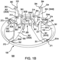
Figures 1A and1B are, respectively, top and bottom perspective views of a guard for an impeller according to an aspect of the invention. -
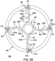
Figures 2A and2B are, respectively, top and bottom views of the aspect of the guard shown inFigure 1A . -
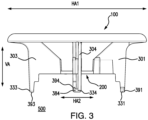
Figure 3 is a side view of the aspect of the guard shown inFigure 1A . -
Figures 4A and4B are, respectively, a top perspective view, and a top view, of an impeller suitable for use with a guard according to an aspect of the invention. -
Figures 5A and5B are, respectively, a top perspective view, and a top view, of an impeller assembly according to an aspect of the invention, comprising the guard as shown inFigure 1A mounted to the impeller shown inFigure 4 . -
Figure 6A is a perspective view of an impeller system according to an aspect of the invention, comprising the impeller assembly shown inFigure 5A , wherein the impeller has a central opening, as well as a pin and seat fitment, the pin passing through the central opening into the seat fitment, for mounting the impeller system to a biocontainer comprising a closed container having an interior volume for containing fluid.Figure 6B is a perspective view of the pin,Figure 6C is a top perspective view of the seat fitment. -
Figure 7A is a perspective view of an impeller system according to another aspect of the invention, comprising an impeller assembly (with the guard removed for ease of viewing) including a base including bearings in a frame, as well as a pin and seat fitment, the pin passing through the central opening into the seat fitment, for mounting the impeller system to a biocontainer comprising a closed container having an interior volume for containing fluid.Figure 7B is a cross-sectional view of the impeller system shown inFigure 7A . -
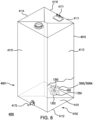
Figure 8 is a side view of a biocontainer system according to an aspect of the invention, comprising a biocontainer comprising a closed container having an interior volume for containing fluid, also including the aspect of the impeller system shown inFigure 6A , wherein the impeller is mounted to the biocontainer. - An aspect of the invention provides a guard for an impeller having at least a first blade and a second blade, each of the first and second blades having front and rear blade faces, an upper edge, an outer edge, an upper outer corner where the upper edge contacts the outer edge, a lower edge, and an inner edge, the guard comprising: (A) an upper annular ring having an upper annular ring horizontal axis and a first internal diameter, the upper annular ring having an upper surface and a lower surface, wherein the lower surface includes at least a first blade receiving groove for receiving the upper outer corner of the first blade, the first blade receiving groove having first and second sides; and a second blade receiving groove for receiving the upper outer corner of the second blade, the second blade receiving groove having first and second sides; (B) a lower annular ring having a lower annular ring horizontal axis and a second internal diameter, wherein the second internal diameter is smaller than the first internal diameter; (C) at least a first brace member and a second brace member, each attached to the upper annular ring and the lower annular ring, each of the first brace member and second brace member being vertically arranged between the upper annular ring and the lower annular ring perpendicular to the upper annular ring horizontal axis and the lower annular ring horizontal axis, (1) the first brace member having a first brace member front wall, a first brace member rear wall, a first brace member outer side wall, and a first brace member inner side wall contacting the lower annular ring, the first brace member front wall or the first brace member rear wall being arranged to face a front or rear blade face of the first blade and forming the second side of the first blade receiving groove; (a) the first brace member having a vertical slot for receiving a portion of an inner edge of the first blade, and a catch for lockably receiving a portion of the lower edge of the first blade; (2) the second brace member having a second brace member front wall, a second brace member rear wall, a second brace member outer side wall and a second brace member inner side wall contacting the lower annular ring, the second brace member front wall or the second brace member rear wall being arranged to face a front or rear blade face of the second blade and forming the second side of the second blade receiving groove; (b) the second brace member having a vertical slot for receiving a portion of an inner edge of the second blade, and a catch for lockably receiving a portion of the lower edge of the second blade.
- In some aspects of the guard, the lower surface of the upper annular ring includes a first protrusion spaced a distance from the front or rear blade face of the first blade and forming the first side of the first blade receiving groove, and a second protrusion spaced a distance from the front or rear blade face of the second blade and forming the first side of the second blade receiving groove.
- Alternatively, or additionally, in some aspects, the first brace member inner side wall includes a first brace member extension forming a part of the vertical slot for receiving a portion of an inner edge of the first blade, and the second brace member inner side wall includes a second brace member extension forming a part of the vertical slot for receiving a portion of an inner edge of the second blade.
- Alternatively, or additionally, in some aspects, the first brace member has a first brace member bottom end including the catch for lockably receiving the portion of the lower edge of the first blade, and the second brace member has a second brace member bottom end including the catch for lockably receiving the portion of the lower edge of the second blade.
- In some aspects, the first brace member catch and the second brace member catch each comprise a hook.
- In another aspect, an impeller assembly is provided, comprising: an impeller having at least a first blade and a second blade, each of the first and second blades having front and rear blade faces, an upper edge, an outer edge, an upper outer corner where the upper edge contacts the outer edge, a lower edge, and an inner edge; and a guard for the impeller, the guard comprising: (A) an upper annular ring having an upper annular ring horizontal axis and a first internal diameter, the upper annular ring having an upper surface and a lower surface, wherein the lower surface includes at least a first blade receiving groove for receiving the upper outer corner of the first blade, the first blade receiving groove having first and second sides; and a second blade receiving groove for receiving the upper outer corner of the second blade, the second blade receiving groove having first and second sides; (B) a lower annular ring having a lower annular ring horizontal axis and a second internal diameter, wherein the second internal diameter is smaller than the first internal diameter; (C) at least a first brace member and a second brace member, each attached to the upper annular ring and the lower annular ring, each of the first brace member and second brace member being vertically arranged between the upper annular ring and the lower annular ring perpendicular to the upper annular ring horizontal axis and the lower annular ring horizontal axis, (1) the first brace member having a first brace member front wall, a first brace member rear wall, a first brace member outer side wall, and a first brace member inner side wall contacting the lower annular ring, the first brace member front wall or the first brace member rear wall being arranged to face a front or rear blade face of the first blade and forming the second side of the first blade receiving groove; (a) the first brace member having a vertical slot for receiving a portion of an inner edge of the first blade, and a catch for lockably receiving a portion of the lower edge of the first blade; (2) the second brace member having a second brace member front wall, a second brace member rear wall, a second brace member outer side wall and a second brace member inner side wall contacting the lower annular ring, the second brace member front wall or the second brace member rear wall being arranged to face a front or rear blade face of the second blade and forming the second side of the second blade receiving groove; (b) the second brace member having a vertical slot for receiving a portion of an inner edge of the second blade, and a catch for lockably receiving a portion of the lower edge of the second blade, mounted to the impeller.
- In yet another aspect, an impeller system is provided, comprising an aspect of the impeller assembly comprising: an impeller having at least a first blade and a second blade, each of the first and second blades having front and rear blade faces, an upper edge, an outer edge, an upper outer corner where the upper edge contacts the outer edge, a lower edge, and an inner edge; and a guard for the impeller, the guard comprising: (A) an upper annular ring having an upper annular ring horizontal axis and a first internal diameter, the upper annular ring having an upper surface and a lower surface, wherein the lower surface includes at least a first blade receiving groove for receiving the upper outer corner of the first blade, the first blade receiving groove having first and second sides; and a second blade receiving groove for receiving the upper outer corner of the second blade, the second blade receiving groove having first and second sides; (B) a lower annular ring having a lower annular ring horizontal axis and a second internal diameter, wherein the second internal diameter is smaller than the first internal diameter; (C) at least a first brace member and a second brace member, each attached to the upper annular ring and the lower annular ring, each of the first brace member and second brace member being vertically arranged between the upper annular ring and the lower annular ring perpendicular to the upper annular ring horizontal axis and the lower annular ring horizontal axis, (1) the first brace member having a first brace member front wall, a first brace member rear wall, a first brace member outer side wall, and a first brace member inner side wall contacting the lower annular ring, the first brace member front wall or the first brace member rear wall being arranged to face a front or rear blade face of the first blade and forming the second side of the first blade receiving groove; (a) the first brace member having a vertical slot for receiving a portion of an inner edge of the first blade, and a catch for lockably receiving a portion of the lower edge of the first blade; (2) the second brace member having a second brace member front wall, a second brace member rear wall, a second brace member outer side wall and a second brace member inner side wall contacting the lower annular ring, the second brace member front wall or the second brace member rear wall being arranged to face a front or rear blade face of the second blade and forming the second side of the second blade receiving groove; (b) the second brace member having a vertical slot for receiving a portion of an inner edge of the second blade, and a catch for lockably receiving a portion of the lower edge of the second blade, mounted to the impeller; a pin, and a seat fitment.
- In another aspect, a biocontainer system is provided, comprising: (a) a biocontainer comprising a closed container having an interior volume suitable for containing fluid, the container comprising a bottom wall, a top wall, at least one side wall, the side wall(s) being joined to the top wall and the bottom wall; and at least an inlet port, and a drain port, wherein the biocontainer further comprises: (b) an aspect of the impeller system comprising an aspect of the impeller assembly comprising: an impeller having at least a first blade and a second blade, each of the first and second blades having front and rear blade faces, an upper edge, an outer edge, an upper outer corner where the upper edge contacts the outer edge, a lower edge, and an inner edge; and a guard for the impeller, the guard comprising: (A) an upper annular ring having an upper annular ring horizontal axis and a first internal diameter, the upper annular ring having an upper surface and a lower surface, wherein the lower surface includes at least a first blade receiving groove for receiving the upper outer corner of the first blade, the first blade receiving groove having first and second sides; and a second blade receiving groove for receiving the upper outer corner of the second blade, the second blade receiving groove having first and second sides; (B) a lower annular ring having a lower annular ring horizontal axis and a second internal diameter, wherein the second internal diameter is smaller than the first internal diameter; (C) at least a first brace member and a second brace member, each attached to the upper annular ring and the lower annular ring, each of the first brace member and second brace member being vertically arranged between the upper annular ring and the lower annular ring perpendicular to the upper annular ring horizontal axis and the lower annular ring horizontal axis, (1) the first brace member having a first brace member front wall, a first brace member rear wall, a first brace member outer side wall, and a first brace member inner side wall contacting the lower annular ring, the first brace member front wall or the first brace member rear wall being arranged to face a front or rear blade face of the first blade and forming the second side of the first blade receiving groove; (a) the first brace member having a vertical slot for receiving a portion of an inner edge of the first blade, and a catch for lockably receiving a portion of the lower edge of the first blade; (2) the second brace member having a second brace member front wall, a second brace member rear wall, a second brace member outer side wall and a second brace member inner side wall contacting the lower annular ring, the second brace member front wall or the second brace member rear wall being arranged to face a front or rear blade face of the second blade and forming the second side of the second blade receiving groove; (b) the second brace member having a vertical slot for receiving a portion of an inner edge of the second blade, and a catch for lockably receiving a portion of the lower edge of the second blade, mounted to the impeller; a pin, and a seat fitment; wherein the impeller is mounted to an inner surface of the bottom wall of the biocontainer.
- In yet another aspect, a method for mounting as aspect of the guard to an impeller is provided, the method comprising: positioning the inner edges of the blades of the impeller in the vertical slots of the respective brace members; positioning the upper outer corners of the blades of the impeller in the respective blade receiving grooves; and positioning the lower edges of the blades of the impeller in the catches of the respective brace members.
- Aspects of the invention are especially suitable for use in closed and/or sterile systems.
- Each of the components of the invention will now be described in more detail below, wherein like components have like reference numbers.
- While suitable impellers can have variety of configurations and any number of blades,
Figures 4A and4B show anillustrative impeller 1000 having, attached to ahub 1100 having acentral opening 1090, four blades:first blade 1001,second blade 1002,third blade 1003, andfourth blade 1004, the respective blades having front and rear blade faces 1001A, 1001B; 1002A, 1002B; 1003A, 1003C; and 1004A, 1004B. Each blade has, respectively, anupper edge outer edge outer corner lower edge inner edge - In preferred aspects, the impeller is a magnetic impeller, in some aspects, a levitating magnetic impeller. If desired, at certain times, a removable metal plate can be placed in contact with the bottom surface of the magnetic impeller, to provide a guard minimizing, if not eliminating, the possible effect of the magnetic field on nearby devices or components.
- Using the aspect shown in
Figures 1A ,1B ,2A ,2B , and3 for reference, aguard 500 for an impeller having at least a first blade and a second blade, each of the first and second blades having front and rear blade faces, an upper edge, an outer edge, an upper outer corner where the upper edge contacts the outer edge, a lower edge, and an inner edge (the impeller as shown inFigures 4A and4B ), comprises an upperannular ring 100 having an upper annular ring horizontal axis HA1 (Figure 3 ) and a firstinternal diameter 175, the upper annular ring having anupper surface 101 and alower surface 102, wherein the lower surface includes at least a firstblade receiving groove 371 for receiving the upper outer corner of the first blade (see,Figure 5A ), the first blade receiving groove having first andsecond sides Figure 2B ); and a secondblade receiving groove 372 for receiving the upper outer corner of the second blade, the second blade receiving groove having first andsecond sides blade receiving grooves second sides - In the illustrated aspects, a lower
annular ring 200 has a lower annular ring horizontal axis HA2 (Figure 3 ), and a secondinternal diameter 275, wherein the secondinternal diameter 275 is smaller than the firstinternal diameter 175; at least afirst brace member 301 and asecond brace member 302, each attached to the upper annular ring and the lower annular ring, each of the first brace member and second brace member being vertically arranged VA between the upper annular ring and the lower annular ring perpendicular to the upper annular ring horizontal axis and the lower annular ring horizontal axis, thefirst brace member 301 having a first bracemember front wall 301A, a first brace memberrear wall 301B, a first brace memberouter side wall 301C, and a first brace memberinner side wall 301D contacting the lower annular ring, the first brace member front wall or the first brace member rear wall being arranged to face a front or rear blade face of the first blade and forming thesecond side 371B of the firstblade receiving groove 371; (a) the first brace member having avertical slot 361 for receiving a portion of an inner edge of the first blade, and acatch 381 for lockably receiving a portion of the lower edge of the first blade (see,Figures 5A and5B ); thesecond brace member 302 having a second bracemember front wall 302A, a second brace memberrear wall 302B, a second brace memberouter side wall 302C and a second brace memberinner side wall 302D contacting the lower annular ring, the second brace member front wall or the second brace member rear wall being arranged to face a front or rear blade face of the second blade and forming thesecond side 372B of the secondblade receiving groove 372; (b) the second brace member having avertical slot 362 for receiving a portion of an inner edge of the second blade, and acatch 382 for lockably receiving a portion of the lower edge of the second blade. In the illustrated aspects, the impeller includes four blades, and the guard includes third andfourth brace members - If desired (see,
Figure 2B ), thelower surface 102 of the upper annular ring can include a first protrusion 351 (shown as doubled protrusions if increased robustness is desired) spaced a distance from the front or rear blade face of the first blade and forming thefirst side 371A of the firstblade receiving groove 371, and a second protrusion 352 (shown as doubled protrusions if increased robustness is desired) spaced a distance from the front or rear blade face of the second blade and forming thefirst side 372A of the secondblade receiving groove 372. The illustrated aspects also show third andfourth protrusions 353, 354 (each shown as doubled protrusions if increased robustness is desired), formingfirst sides blade receiving grooves Figure 1B showing 351A, 352A, 353A, and 354A), for ease of guiding the upper outer corners of the blades into the blade receiving grooves. - Preferably, the first brace member
inner side wall 301D includes a firstbrace member extension 311 forming a part of thevertical slot 361 for receiving a portion of an inner edge of the first blade, and the second brace memberinner side wall 302D includes a secondbrace member extension 312 forming a part of thevertical slot 362 for receiving a portion of an inner edge of the second blade. The illustrated aspect also show third and fourth brace member inner sidewalls including extensions vertical slots arm 311A andfront wall 301A inFigure 1A ) - In the illustrated aspect, the
first brace member 301 has a first bracemember bottom end 331 including thecatch 381 for lockably receiving the portion of the lower edge of the first blade (see,Figure 5A ), and thesecond brace member 302 has a second bracemember bottom end 332 including thecatch 382 for lockably receiving the portion of the lower edge of the second blade. The illustrated aspect also show third and fourth bracemember bottom ends catches - Preferably, for ease of lockably receiving portions of the lower edges of the blades, brace member catches 381, 382 each respective comprise a hook (curved or bent back at an angle) 391, 392, wherein the figures also show
catches hooks -
Figures 5A and5B show animpeller assembly 2000 according to an aspect of the invention, wherein the aspect of theguard 500 shown inFigure 1A is engaged with the aspect of theimpeller 1000 shown inFigure 4A , wherein portions of the blades are received in the components of the guard as discussed above. Thus, the inner edges of the blades are positioned in the vertical slots of the guard, the upper outer corners of the blades are positioned in the blade receiving grooves, optionally after contacting the protrusions wherein contacting the angled portions of the protrusions helps guide the upper outer corners into the blade receiving grooves, and the portions of the lower edges of the blades are lockably received in the catches. In this context, "lockably received" indicates that removing the lower edges of the blades from the catches is difficult. -
Figure 6A shows a perspective view animpeller assembly 3000 according to an aspect of the invention, comprising the aspect of the impeller assembly shown inFigures 5A and5B wherein the assembly further comprising apin 1300 and aseat fitment 1350, for mounting on a biocontainer (biocontainer 4001 shown inFigure 8 ). As shown inFigure 6B , the illustratedpin 1300 has ahead 1301, atip 1302, ashaft 1310 connected to the head at one end and the tip at the other end, wherein the shaft also includesribs 1315 and the tip includes aridge 1320, the pin having chamfers 1325 between the shaft and the tip. As shown inFigure 6C , theseat fitment 1350 has a first (upper)surface 1351 and a second (lower)surface 1352. As will be discussed in more detail below, thelower surface 1352 will be secured to (e.g., welded) to the inner surface of the biocontainer. - The illustrated
fitment 1350 has ahollow extension 1375 with acentral opening 1390 at a first (upper)end 1376 of the extension for receiving thepin 1300, wherein thefitment 1350 also includes an internal fitment chamfer 1326 (shown inFigure 7B ).Figure 6C shows the extension extending upwardly from thefirst surface 1351, the extension also extends downwardly from thelower surface 1352 and is closed and the second (lower) end (see,Figure 7B showing another aspect of animpeller assembly 3000A wherein the extension includes a closed lower end 1377). Once thepin 1300 is fully inserted through the impeller opening 1090 and the fitment opening 1390, theridge 1320 provides a friction fit against the lower portion of thefitment chamfer 1326, and thepin chamfers 1325 also provide friction, preventing the pin from disengaging from the fitment. -
Figures 7A (perspective view) and 7B (sectional view) show anotherimpeller assembly 3000A according to an aspect of the invention, generally similar to the aspect shown inFigure 6A . However, the aspect shown inFigures 7A and7B includes abearing assembly 1400 arranged between the hub of the impeller and thefirst surface 1351 of theseat fitment 1350. As with theimpeller assembly 3000, the illustrated aspect ofimpeller assembly 3000A includes apin 1300 fully inserted through theimpeller opening 1090 and thefitment opening 1390, theridge 1320 provides a friction fit against the lower portion of thefitment chamfer 1326, and thepin chamfers 1325 also provide friction, preventing the pin from disengaging from the fitment. - Aspects of the invention are suitable for use with a wide variety of biocontainers and biocontainer systems, preferably, single-use biocontainers and biocontainer systems, and/or for maintaining closed, sterile systems. Biocontainers can have, for example, any suitable shape and interior volume, and any number of ports and/or fittings and/or fluid conduits such as tubing. Biocontainers have at least two ports, i.e., an inlet port and a drain port, and may have one or more additional ports, e.g., one or more of any of the following: for sampling, venting, monitoring (e.g., any one or more of the following: oxygen, temperature, pH), and additives. Biocontainers omprises a bottom wall, a top wall, and at least one side wall, the side wall(s) being joined to the top wall and the bottom wall.
-
Figure 8 shows anillustrative biocontainer system 4000 according to an aspect of the invention, comprising abiocontainer 4001 comprising a closed container having an interior volume for containing fluid, wherein an the aspect of the impeller system (e.g., as shown inFigures 6A or7A ) is mounted on thebiocontainer 4001. The illustrated biocontainer 4001 comprises aflexible biocontainer bag 4010, the bag comprising aninlet port 4171, anoutlet port 4172, atop wall 4111, abottom wall 4112 having aninner surface 4151 and anouter surface 4152, and opposingside walls lower surface 1352 of theseat fitment 1350 is secured to (e.g., welded) to the inner surface 1451 of the biocontainer. While not shown inFigure 8 , the closedlower end 1377 of the seat fitment extension passes through theouter surface 4152 of the biocontainer for cooperation with a drive system including a motor for rotating the impeller. - A number of materials and processes are suitable for producing guards according to aspects of the invention. Suitable materials include for example, thermoplastic resins such as polypropylene, and polyethylene (e.g., high density polyethylene). A suitable process includes, for example, injection molding.
- A variety of impellers are suitable for use in aspects of the invention, and are commercially available. Suitable impellers include magnetic and levitating impellers, for example, available under the names LEVMIXER® mixer and ALLEGRO™ Magnetic Mixer (Pall Corporation, East Hills, NY).
- A variety of biocontainers and biocontainer systems impellers are suitable for use in aspects of the invention (i.e., impeller systems according to aspects of the system can be mounted on the biocontainers), and are commercially available.
- All references, including publications, patent applications, and patents, cited herein are hereby incorporated by reference to the same extent as if each reference were individually and specifically indicated to be incorporated by reference and were set forth in its entirety herein.
- The use of the terms "a" and "an" and "the" and "at least one" and similar referents in the context of describing the invention (especially in the context of the following claims) are to be construed to cover both the singular and the plural, unless otherwise indicated herein or clearly contradicted by context. The use of the term "at least one" followed by a list of one or more items (for example, "at least one of A and B") is to be construed to mean one item selected from the listed items (A or B) or any combination of two or more of the listed items (A and B), unless otherwise indicated herein or clearly contradicted by context. The terms "comprising," "having," "including," and "containing" are to be construed as open-ended terms (i.e., meaning "including, but not limited to,") unless otherwise noted. Recitation of ranges of values herein are merely intended to serve as a shorthand method of referring individually to each separate value falling within the range, unless otherwise indicated herein, and each separate value is incorporated into the specification as if it were individually recited herein. All methods described herein can be performed in any suitable order unless otherwise indicated herein or otherwise clearly contradicted by context. The use of any and all examples, or exemplary language (e.g., "such as") provided herein, is intended merely to better illuminate the invention and does not pose a limitation on the scope of the invention unless otherwise claimed. No language in the specification should be construed as indicating any non-claimed element as essential to the practice of the invention.
- Preferred aspects of this invention are described herein, including the best mode known to the inventors for carrying out the invention. Variations of those preferred aspects may become apparent to those of ordinary skill in the art upon reading the foregoing description. The inventors expect skilled artisans to employ such variations as appropriate, and the inventors intend for the invention to be practiced otherwise than as specifically described herein. Accordingly, this invention includes all modifications and equivalents of the subject matter recited in the claims appended hereto as permitted by applicable law. Moreover, any combination of the above-described elements in all possible variations thereof is encompassed by the invention unless otherwise indicated herein or otherwise clearly contradicted by context.
Claims (9)
- A guard for an impeller having at least a first blade and a second blade, each of the first and second blades having front and rear blade faces, an upper edge, an outer edge, an upper outer corner where the upper edge contacts the outer edge, a lower edge, and an inner edge, the guard comprising:(A) an upper annular ring having an upper annular ring horizontal axis and a first internal diameter, the upper annular ring having an upper surface and a lower surface, wherein the lower surface includes at least a first blade receiving groove for receiving the upper outer corner of the first blade, the first blade receiving groove having first and second sides; and a second blade receiving groove for receiving the upper outer corner of the second blade, the second blade receiving groove having first and second sides;(B) a lower annular ring having a lower annular ring horizontal axis and a second internal diameter, wherein the second internal diameter is smaller than the first internal diameter;(C) at least a first brace member and a second brace member, each attached to the upper annular ring and the lower annular ring, each of the first brace member and second brace member being vertically arranged between the upper annular ring and the lower annular ring perpendicular to the upper annular ring horizontal axis and the lower annular ring horizontal axis,(1) the first brace member having a first brace member front wall, a first brace member rear wall, a first brace member outer side wall, and a first brace member inner side wall contacting the lower annular ring, the first brace member front wall or the first brace member rear wall being arranged to face a front or rear blade face of the first blade and forming the second side of the first blade receiving groove;(a) the first brace member having a vertical slot for receiving a portion of an inner edge of the first blade, and a catch for lockably receiving a portion of the lower edge of the first blade;(2) the second brace member having a second brace member front wall, a second brace member rear wall, a second brace member outer side wall and a second brace member inner side wall contacting the lower annular ring, the second brace member front wall or the second brace member rear wall being arranged to face a front or rear blade face of the second blade and forming the second side of the second blade receiving groove;
(b) the second brace member having a vertical slot for receiving a portion of an inner edge of the second blade, and a catch for lockably receiving a portion of the lower edge of the second blade. - The guard of claim 1, wherein the lower surface of the upper annular ring includes a first protrusion spaced a distance from the front or rear blade face of the first blade and forming the first side of the first blade receiving groove, and a second protrusion spaced a distance from the front or rear blade face of the second blade and forming the first side of the second blade receiving groove.
- The guard of claim 1 or 2, wherein the first brace member inner side wall includes a first brace member extension forming a part of the vertical slot for receiving a portion of an inner edge of the first blade, and the second brace member inner side wall includes a second brace member extension forming a part of the vertical slot for receiving a portion of an inner edge of the second blade.
- The guard of any one of claims 1-3, wherein the first brace member has a first brace member bottom end including the catch for lockably receiving the portion of the lower edge of the first blade, and the second brace member has a second brace member bottom end including the catch for lockably receiving the portion of the lower edge of the second blade.
- The guard of any one of claims 1-4, wherein the first brace member catch and the second brace member catch each comprise a hook.
- An impeller assembly comprising:an impeller having at least a first blade and a second blade, each of the first and second blades having front and rear blade faces, an upper edge, an outer edge, an upper outer corner where the upper edge contacts the outer edge, a lower edge, and an inner edge; andthe guard of any one of claims 1-5, mounted to the impeller.
- A method for mounting the guard of any one of claims 1-5 to an impeller, the method comprising:positioning the inner edges of the blades of the impeller in the vertical slots of the respective brace members;positioning the upper outer corners of the blades of the impeller in the respective blade receiving grooves; andpositioning the lower edges of the blades of the impeller in the catches of the respective brace members.
- An impeller system, comprising the impeller assembly of claim 6, wherein the impeller has a central opening, the impeller assembly further comprising a pin and a seat fitment.
- A biocontainer system comprising: (a) a biocontainer comprising a closed container having an interior volume suitable for containing fluid, the container comprising a bottom wall, a top wall, at least one side wall, the side wall(s) being joined to the top wall and the bottom wall; and at least an inlet port, and a drain port, wherein the biocontainer further comprises: (b) the impeller system of claim 8, wherein the impeller is mounted to an inner surface of the bottom wall of the biocontainer.
Applications Claiming Priority (1)
| Application Number | Priority Date | Filing Date | Title |
|---|---|---|---|
| US17/495,598 US12233386B2 (en) | 2021-10-06 | 2021-10-06 | Impeller guard |
Publications (2)
| Publication Number | Publication Date |
|---|---|
| EP4163007A1 true EP4163007A1 (en) | 2023-04-12 |
| EP4163007B1 EP4163007B1 (en) | 2024-11-06 |
Family
ID=82385461
Family Applications (1)
| Application Number | Title | Priority Date | Filing Date |
|---|---|---|---|
| EP22181662.2A Active EP4163007B1 (en) | 2021-10-06 | 2022-06-28 | Impeller guard |
Country Status (5)
| Country | Link |
|---|---|
| US (1) | US12233386B2 (en) |
| EP (1) | EP4163007B1 (en) |
| JP (1) | JP7416366B2 (en) |
| KR (1) | KR102707946B1 (en) |
| CN (2) | CN121775698A (en) |
Families Citing this family (3)
| Publication number | Priority date | Publication date | Assignee | Title |
|---|---|---|---|---|
| US12478937B2 (en) * | 2021-02-11 | 2025-11-25 | Leah Lupo | Portable warming blender |
| DE102023119455A1 (en) * | 2023-07-24 | 2025-01-30 | mevidual Group GmbH | Device for producing a personal care product, cosmetic or household product |
| US20250303375A1 (en) * | 2024-04-02 | 2025-10-02 | Cytiva Us Llc | Small volume mixing device |
Citations (5)
| Publication number | Priority date | Publication date | Assignee | Title |
|---|---|---|---|---|
| US5758965A (en) * | 1996-12-05 | 1998-06-02 | General Signal Corporation | Mixer system |
| US5865539A (en) * | 1997-09-30 | 1999-02-02 | Rogers; Mike | Rotary mixing device for fluidic material |
| US9744507B2 (en) * | 2012-11-29 | 2017-08-29 | Emd Millipore Corporation | 2D low level mixing bag for storage and shipping |
| US10005052B2 (en) * | 2007-10-04 | 2018-06-26 | Sartorius Stedim Fmt Sas | Vessel for processing a biopharmaceutical product including protection means |
| US20200179885A1 (en) * | 2018-12-10 | 2020-06-11 | Pall Corporation | Radially driven agitator |
Family Cites Families (19)
| Publication number | Priority date | Publication date | Assignee | Title |
|---|---|---|---|---|
| US1778790A (en) * | 1927-08-30 | 1930-10-21 | Julius Haber | Gaseous-fuel-mixing device |
| US6564881B2 (en) * | 2000-08-08 | 2003-05-20 | John P. Murtagh | Mixing hoe and blade |
| US6881033B2 (en) * | 2002-09-30 | 2005-04-19 | Fisher & Paykel Healthcare Limited | Impeller |
| US6966757B2 (en) * | 2003-12-18 | 2005-11-22 | Spx Corporation | Scraper blade attachment apparatus and method with split pin |
| EP2114554A1 (en) * | 2007-02-21 | 2009-11-11 | Levtech Inc. | Roller bearing for a fluid-agitating element and associated vessel |
| US7740401B2 (en) | 2007-04-16 | 2010-06-22 | Vita-Mix Corporation | Food mixing machine and agitator therefor |
| SE534771C2 (en) * | 2010-03-17 | 2011-12-13 | Itt Mfg Enterprises Inc | Propeller assembly comprising a hub and at least two blades |
| CA2848652C (en) | 2011-09-16 | 2020-04-14 | Thomas Erdenberger | Single-use mixing and bioreactor systems |
| KR101115420B1 (en) * | 2011-10-11 | 2012-02-28 | (주) 오스타테크 | Liquid Mixing Dissolution Promoter |
| GB2499627A (en) * | 2012-02-23 | 2013-08-28 | Napier Turbochargers Ltd | Turbocharger casing |
| EP3628396B1 (en) * | 2012-04-06 | 2024-11-20 | Life Technologies Corporation | Fluid mixing system |
| DE102012020384B4 (en) * | 2012-10-18 | 2014-07-10 | Sartorius Stedim Biotech Gmbh | Bioreactor, reactor bag for it and stirrer for circulation of its contents |
| US9975095B2 (en) | 2012-11-29 | 2018-05-22 | Emd Millipore Corporation | Container having magnetic impeller assembly with hood |
| US9248420B2 (en) | 2013-12-16 | 2016-02-02 | Pall Corporation | High turndown impeller |
| US9808780B2 (en) * | 2014-03-21 | 2017-11-07 | Sartorius Stedim North America Inc. | System, container, device, and method for mixing |
| US9878295B2 (en) | 2015-04-13 | 2018-01-30 | Pall Corporation | Fluid impeller for bioprocessing |
| WO2016191874A1 (en) * | 2015-06-01 | 2016-12-08 | Dynamix Agitators Inc. | Mixing assembly |
| KR102064898B1 (en) * | 2018-01-02 | 2020-01-15 | 주식회사 주신기계 | Impeller assembly for agitator |
| CN108543644A (en) * | 2018-05-22 | 2018-09-18 | 长春瑞泰博尔克科技有限公司 | The method and protective device that non-coated face is protected during rotary coating impeller |
-
2021
- 2021-10-06 US US17/495,598 patent/US12233386B2/en active Active
-
2022
- 2022-06-28 EP EP22181662.2A patent/EP4163007B1/en active Active
- 2022-07-01 JP JP2022107254A patent/JP7416366B2/en active Active
- 2022-08-08 CN CN202511787832.7A patent/CN121775698A/en active Pending
- 2022-08-08 CN CN202210941697.7A patent/CN115920690B/en active Active
- 2022-09-30 KR KR1020220125150A patent/KR102707946B1/en active Active
Patent Citations (5)
| Publication number | Priority date | Publication date | Assignee | Title |
|---|---|---|---|---|
| US5758965A (en) * | 1996-12-05 | 1998-06-02 | General Signal Corporation | Mixer system |
| US5865539A (en) * | 1997-09-30 | 1999-02-02 | Rogers; Mike | Rotary mixing device for fluidic material |
| US10005052B2 (en) * | 2007-10-04 | 2018-06-26 | Sartorius Stedim Fmt Sas | Vessel for processing a biopharmaceutical product including protection means |
| US9744507B2 (en) * | 2012-11-29 | 2017-08-29 | Emd Millipore Corporation | 2D low level mixing bag for storage and shipping |
| US20200179885A1 (en) * | 2018-12-10 | 2020-06-11 | Pall Corporation | Radially driven agitator |
Also Published As
| Publication number | Publication date |
|---|---|
| CN115920690B (en) | 2025-12-12 |
| JP2023055617A (en) | 2023-04-18 |
| JP7416366B2 (en) | 2024-01-17 |
| US20230106503A1 (en) | 2023-04-06 |
| KR20230049553A (en) | 2023-04-13 |
| EP4163007B1 (en) | 2024-11-06 |
| CN115920690A (en) | 2023-04-07 |
| KR102707946B1 (en) | 2024-09-23 |
| US12233386B2 (en) | 2025-02-25 |
| CN121775698A (en) | 2026-04-03 |
Similar Documents
| Publication | Publication Date | Title |
|---|---|---|
| EP4163007B1 (en) | Impeller guard | |
| US10441927B2 (en) | Impeller for bioprocessing | |
| EP2228128B1 (en) | Mixing vessel having a receiver for holding a fluid-agitating element | |
| US9248420B2 (en) | High turndown impeller | |
| EP2889080B1 (en) | Mechanical agitator with seal housing assembly | |
| US8182137B2 (en) | Mixing bag or vessel with a fluid-agitating element | |
| EP1031371A1 (en) | Filtering unit having separately attachable filter cassette and method of filtering | |
| EP3763436B1 (en) | Stirring device with a shaft, adapted to be mounted in a fluid-mixing bioreactor, and method for assembling a stirring device | |
| SG181569A1 (en) | Configurable port fitment, kit, and related methods | |
| JPH08500527A (en) | Micro Porous Filter Filter Assembly | |
| CN223846663U (en) | A dialysis bag clamping and feeding structure, and a dialysis device. | |
| EP4168788B1 (en) | Sensor fitting for biotech process bag |
Legal Events
| Date | Code | Title | Description |
|---|---|---|---|
| PUAI | Public reference made under article 153(3) epc to a published international application that has entered the european phase |
Free format text: ORIGINAL CODE: 0009012 |
|
| STAA | Information on the status of an ep patent application or granted ep patent |
Free format text: STATUS: THE APPLICATION HAS BEEN PUBLISHED |
|
| STAA | Information on the status of an ep patent application or granted ep patent |
Free format text: STATUS: REQUEST FOR EXAMINATION WAS MADE |
|
| AK | Designated contracting states |
Kind code of ref document: A1 Designated state(s): AL AT BE BG CH CY CZ DE DK EE ES FI FR GB GR HR HU IE IS IT LI LT LU LV MC MK MT NL NO PL PT RO RS SE SI SK SM TR |
|
| 17P | Request for examination filed |
Effective date: 20230327 |
|
| RBV | Designated contracting states (corrected) |
Designated state(s): AL AT BE BG CH CY CZ DE DK EE ES FI FR GB GR HR HU IE IS IT LI LT LU LV MC MK MT NL NO PL PT RO RS SE SI SK SM TR |
|
| STAA | Information on the status of an ep patent application or granted ep patent |
Free format text: STATUS: EXAMINATION IS IN PROGRESS |
|
| 17Q | First examination report despatched |
Effective date: 20230607 |
|
| P01 | Opt-out of the competence of the unified patent court (upc) registered |
Effective date: 20230530 |
|
| GRAP | Despatch of communication of intention to grant a patent |
Free format text: ORIGINAL CODE: EPIDOSNIGR1 |
|
| STAA | Information on the status of an ep patent application or granted ep patent |
Free format text: STATUS: GRANT OF PATENT IS INTENDED |
|
| RIC1 | Information provided on ipc code assigned before grant |
Ipc: C12M 1/06 20060101ALN20240522BHEP Ipc: B01F 35/60 20220101ALI20240522BHEP Ipc: B01F 35/513 20220101ALI20240522BHEP Ipc: B01F 33/453 20220101AFI20240522BHEP |
|
| INTG | Intention to grant announced |
Effective date: 20240613 |
|
| GRAS | Grant fee paid |
Free format text: ORIGINAL CODE: EPIDOSNIGR3 |
|
| GRAA | (expected) grant |
Free format text: ORIGINAL CODE: 0009210 |
|
| STAA | Information on the status of an ep patent application or granted ep patent |
Free format text: STATUS: THE PATENT HAS BEEN GRANTED |
|
| AK | Designated contracting states |
Kind code of ref document: B1 Designated state(s): AL AT BE BG CH CY CZ DE DK EE ES FI FR GB GR HR HU IE IS IT LI LT LU LV MC MK MT NL NO PL PT RO RS SE SI SK SM TR |
|
| REG | Reference to a national code |
Ref country code: GB Ref legal event code: FG4D |
|
| REG | Reference to a national code |
Ref country code: CH Ref legal event code: EP |
|
| REG | Reference to a national code |
Ref country code: DE Ref legal event code: R096 Ref document number: 602022007393 Country of ref document: DE |
|
| REG | Reference to a national code |
Ref country code: IE Ref legal event code: FG4D |
|
| REG | Reference to a national code |
Ref country code: NL Ref legal event code: FP |
|
| REG | Reference to a national code |
Ref country code: LT Ref legal event code: MG9D |
|
| REG | Reference to a national code |
Ref country code: DE Ref legal event code: R081 Ref document number: 602022007393 Country of ref document: DE Owner name: PALL MEDISTAD B.V., NL Free format text: FORMER OWNERS: PALL CORPORATION, PORT WASHINGTON, NY, US; PALL MEDISTAD B.V., MEDEMBLIK, NL Ref country code: DE Ref legal event code: R081 Ref document number: 602022007393 Country of ref document: DE Owner name: CYTIVA US LLC, MARLBOROUGH, US Free format text: FORMER OWNERS: PALL CORPORATION, PORT WASHINGTON, NY, US; PALL MEDISTAD B.V., MEDEMBLIK, NL |
|
| REG | Reference to a national code |
Ref country code: NL Ref legal event code: PD Owner name: PALL MEDISTAD B.V.; NL Free format text: DETAILS ASSIGNMENT: CHANGE OF OWNER(S), ASSIGNMENT; FORMER OWNER NAME: PALL MEDISTAD B.V. Effective date: 20250310 |
|
| RAP2 | Party data changed (patent owner data changed or rights of a patent transferred) |
Owner name: PALL MEDISTAD B.V. Owner name: CYTIVA US LLC |
|
| PG25 | Lapsed in a contracting state [announced via postgrant information from national office to epo] |
Ref country code: PT Free format text: LAPSE BECAUSE OF FAILURE TO SUBMIT A TRANSLATION OF THE DESCRIPTION OR TO PAY THE FEE WITHIN THE PRESCRIBED TIME-LIMIT Effective date: 20250306 Ref country code: HR Free format text: LAPSE BECAUSE OF FAILURE TO SUBMIT A TRANSLATION OF THE DESCRIPTION OR TO PAY THE FEE WITHIN THE PRESCRIBED TIME-LIMIT Effective date: 20241106 Ref country code: IS Free format text: LAPSE BECAUSE OF FAILURE TO SUBMIT A TRANSLATION OF THE DESCRIPTION OR TO PAY THE FEE WITHIN THE PRESCRIBED TIME-LIMIT Effective date: 20250306 |
|
| PG25 | Lapsed in a contracting state [announced via postgrant information from national office to epo] |
Ref country code: FI Free format text: LAPSE BECAUSE OF FAILURE TO SUBMIT A TRANSLATION OF THE DESCRIPTION OR TO PAY THE FEE WITHIN THE PRESCRIBED TIME-LIMIT Effective date: 20241106 |
|
| REG | Reference to a national code |
Ref country code: AT Ref legal event code: MK05 Ref document number: 1738767 Country of ref document: AT Kind code of ref document: T Effective date: 20241106 |
|
| PG25 | Lapsed in a contracting state [announced via postgrant information from national office to epo] |
Ref country code: BG Free format text: LAPSE BECAUSE OF FAILURE TO SUBMIT A TRANSLATION OF THE DESCRIPTION OR TO PAY THE FEE WITHIN THE PRESCRIBED TIME-LIMIT Effective date: 20241106 |
|
| PG25 | Lapsed in a contracting state [announced via postgrant information from national office to epo] |
Ref country code: ES Free format text: LAPSE BECAUSE OF FAILURE TO SUBMIT A TRANSLATION OF THE DESCRIPTION OR TO PAY THE FEE WITHIN THE PRESCRIBED TIME-LIMIT Effective date: 20241106 |
|
| PG25 | Lapsed in a contracting state [announced via postgrant information from national office to epo] |
Ref country code: NO Free format text: LAPSE BECAUSE OF FAILURE TO SUBMIT A TRANSLATION OF THE DESCRIPTION OR TO PAY THE FEE WITHIN THE PRESCRIBED TIME-LIMIT Effective date: 20250206 |
|
| PG25 | Lapsed in a contracting state [announced via postgrant information from national office to epo] |
Ref country code: AT Free format text: LAPSE BECAUSE OF FAILURE TO SUBMIT A TRANSLATION OF THE DESCRIPTION OR TO PAY THE FEE WITHIN THE PRESCRIBED TIME-LIMIT Effective date: 20241106 Ref country code: LV Free format text: LAPSE BECAUSE OF FAILURE TO SUBMIT A TRANSLATION OF THE DESCRIPTION OR TO PAY THE FEE WITHIN THE PRESCRIBED TIME-LIMIT Effective date: 20241106 Ref country code: GR Free format text: LAPSE BECAUSE OF FAILURE TO SUBMIT A TRANSLATION OF THE DESCRIPTION OR TO PAY THE FEE WITHIN THE PRESCRIBED TIME-LIMIT Effective date: 20250207 |
|
| PG25 | Lapsed in a contracting state [announced via postgrant information from national office to epo] |
Ref country code: PL Free format text: LAPSE BECAUSE OF FAILURE TO SUBMIT A TRANSLATION OF THE DESCRIPTION OR TO PAY THE FEE WITHIN THE PRESCRIBED TIME-LIMIT Effective date: 20241106 |
|
| PG25 | Lapsed in a contracting state [announced via postgrant information from national office to epo] |
Ref country code: RS Free format text: LAPSE BECAUSE OF FAILURE TO SUBMIT A TRANSLATION OF THE DESCRIPTION OR TO PAY THE FEE WITHIN THE PRESCRIBED TIME-LIMIT Effective date: 20250206 |
|
| REG | Reference to a national code |
Ref country code: BE Ref legal event code: PD Owner name: CYTIVA US LLC; US Free format text: DETAILS ASSIGNMENT: CHANGE OF OWNER(S), ASSIGNMENT; FORMER OWNER NAME: PALL CORPORATION Effective date: 20250310 |
|
| REG | Reference to a national code |
Ref country code: GB Ref legal event code: 732E Free format text: REGISTERED BETWEEN 20250522 AND 20250528 |
|
| PG25 | Lapsed in a contracting state [announced via postgrant information from national office to epo] |
Ref country code: SM Free format text: LAPSE BECAUSE OF FAILURE TO SUBMIT A TRANSLATION OF THE DESCRIPTION OR TO PAY THE FEE WITHIN THE PRESCRIBED TIME-LIMIT Effective date: 20241106 |
|
| PGFP | Annual fee paid to national office [announced via postgrant information from national office to epo] |
Ref country code: DE Payment date: 20250626 Year of fee payment: 4 |
|
| PG25 | Lapsed in a contracting state [announced via postgrant information from national office to epo] |
Ref country code: DK Free format text: LAPSE BECAUSE OF FAILURE TO SUBMIT A TRANSLATION OF THE DESCRIPTION OR TO PAY THE FEE WITHIN THE PRESCRIBED TIME-LIMIT Effective date: 20241106 |
|
| PGFP | Annual fee paid to national office [announced via postgrant information from national office to epo] |
Ref country code: NL Payment date: 20250624 Year of fee payment: 4 Ref country code: BE Payment date: 20250624 Year of fee payment: 4 |
|
| PG25 | Lapsed in a contracting state [announced via postgrant information from national office to epo] |
Ref country code: EE Free format text: LAPSE BECAUSE OF FAILURE TO SUBMIT A TRANSLATION OF THE DESCRIPTION OR TO PAY THE FEE WITHIN THE PRESCRIBED TIME-LIMIT Effective date: 20241106 |
|
| PGFP | Annual fee paid to national office [announced via postgrant information from national office to epo] |
Ref country code: FR Payment date: 20250624 Year of fee payment: 4 |
|
| PG25 | Lapsed in a contracting state [announced via postgrant information from national office to epo] |
Ref country code: RO Free format text: LAPSE BECAUSE OF FAILURE TO SUBMIT A TRANSLATION OF THE DESCRIPTION OR TO PAY THE FEE WITHIN THE PRESCRIBED TIME-LIMIT Effective date: 20241106 |
|
| PG25 | Lapsed in a contracting state [announced via postgrant information from national office to epo] |
Ref country code: SK Free format text: LAPSE BECAUSE OF FAILURE TO SUBMIT A TRANSLATION OF THE DESCRIPTION OR TO PAY THE FEE WITHIN THE PRESCRIBED TIME-LIMIT Effective date: 20241106 |
|
| PG25 | Lapsed in a contracting state [announced via postgrant information from national office to epo] |
Ref country code: CZ Free format text: LAPSE BECAUSE OF FAILURE TO SUBMIT A TRANSLATION OF THE DESCRIPTION OR TO PAY THE FEE WITHIN THE PRESCRIBED TIME-LIMIT Effective date: 20241106 |
|
| PG25 | Lapsed in a contracting state [announced via postgrant information from national office to epo] |
Ref country code: IT Free format text: LAPSE BECAUSE OF FAILURE TO SUBMIT A TRANSLATION OF THE DESCRIPTION OR TO PAY THE FEE WITHIN THE PRESCRIBED TIME-LIMIT Effective date: 20241106 |
|
| REG | Reference to a national code |
Ref country code: DE Ref legal event code: R097 Ref document number: 602022007393 Country of ref document: DE |
|
| PG25 | Lapsed in a contracting state [announced via postgrant information from national office to epo] |
Ref country code: SE Free format text: LAPSE BECAUSE OF FAILURE TO SUBMIT A TRANSLATION OF THE DESCRIPTION OR TO PAY THE FEE WITHIN THE PRESCRIBED TIME-LIMIT Effective date: 20241106 |
|
| PLBE | No opposition filed within time limit |
Free format text: ORIGINAL CODE: 0009261 |
|
| STAA | Information on the status of an ep patent application or granted ep patent |
Free format text: STATUS: NO OPPOSITION FILED WITHIN TIME LIMIT |
|
| 26N | No opposition filed |
Effective date: 20250807 |
|
| REG | Reference to a national code |
Ref country code: CH Ref legal event code: H13 Free format text: ST27 STATUS EVENT CODE: U-0-0-H10-H13 (AS PROVIDED BY THE NATIONAL OFFICE) Effective date: 20260127 |
|
| PG25 | Lapsed in a contracting state [announced via postgrant information from national office to epo] |
Ref country code: MC Free format text: LAPSE BECAUSE OF FAILURE TO SUBMIT A TRANSLATION OF THE DESCRIPTION OR TO PAY THE FEE WITHIN THE PRESCRIBED TIME-LIMIT Effective date: 20241106 |
|
| PG25 | Lapsed in a contracting state [announced via postgrant information from national office to epo] |
Ref country code: LU Free format text: LAPSE BECAUSE OF NON-PAYMENT OF DUE FEES Effective date: 20250628 |
|
| PG25 | Lapsed in a contracting state [announced via postgrant information from national office to epo] |
Ref country code: IE Free format text: LAPSE BECAUSE OF NON-PAYMENT OF DUE FEES Effective date: 20250628 |
|
| PG25 | Lapsed in a contracting state [announced via postgrant information from national office to epo] |
Ref country code: CH Free format text: LAPSE BECAUSE OF NON-PAYMENT OF DUE FEES Effective date: 20250630 |