EP4162336B1 - Method and control unit for handling safe stop mode of a vehicle - Google Patents
Method and control unit for handling safe stop mode of a vehicle Download PDFInfo
- Publication number
- EP4162336B1 EP4162336B1 EP20733225.5A EP20733225A EP4162336B1 EP 4162336 B1 EP4162336 B1 EP 4162336B1 EP 20733225 A EP20733225 A EP 20733225A EP 4162336 B1 EP4162336 B1 EP 4162336B1
- Authority
- EP
- European Patent Office
- Prior art keywords
- vehicle
- stop mode
- safe stop
- control unit
- input device
- Prior art date
- Legal status (The legal status is an assumption and is not a legal conclusion. Google has not performed a legal analysis and makes no representation as to the accuracy of the status listed.)
- Active
Links
Images

Classifications
-
- B—PERFORMING OPERATIONS; TRANSPORTING
- B60—VEHICLES IN GENERAL
- B60W—CONJOINT CONTROL OF VEHICLE SUB-UNITS OF DIFFERENT TYPE OR DIFFERENT FUNCTION; CONTROL SYSTEMS SPECIALLY ADAPTED FOR HYBRID VEHICLES; ROAD VEHICLE DRIVE CONTROL SYSTEMS FOR PURPOSES NOT RELATED TO THE CONTROL OF A PARTICULAR SUB-UNIT
- B60W60/00—Drive control systems specially adapted for autonomous road vehicles
- B60W60/005—Handover processes
- B60W60/0053—Handover processes from vehicle to occupant
-
- B—PERFORMING OPERATIONS; TRANSPORTING
- B60—VEHICLES IN GENERAL
- B60W—CONJOINT CONTROL OF VEHICLE SUB-UNITS OF DIFFERENT TYPE OR DIFFERENT FUNCTION; CONTROL SYSTEMS SPECIALLY ADAPTED FOR HYBRID VEHICLES; ROAD VEHICLE DRIVE CONTROL SYSTEMS FOR PURPOSES NOT RELATED TO THE CONTROL OF A PARTICULAR SUB-UNIT
- B60W50/00—Details of control systems for road vehicle drive control not related to the control of a particular sub-unit, e.g. process diagnostic or vehicle driver interfaces
- B60W50/08—Interaction between the driver and the control system
- B60W50/082—Selecting or switching between different modes of propelling
-
- B—PERFORMING OPERATIONS; TRANSPORTING
- B60—VEHICLES IN GENERAL
- B60Q—ARRANGEMENT OF SIGNALLING OR LIGHTING DEVICES, THE MOUNTING OR SUPPORTING THEREOF OR CIRCUITS THEREFOR, FOR VEHICLES IN GENERAL
- B60Q1/00—Arrangement of optical signalling or lighting devices, the mounting or supporting thereof or circuits therefor
- B60Q1/26—Arrangement of optical signalling or lighting devices, the mounting or supporting thereof or circuits therefor the devices being primarily intended to indicate the vehicle, or parts thereof, or to give signals, to other traffic
- B60Q1/50—Arrangement of optical signalling or lighting devices, the mounting or supporting thereof or circuits therefor the devices being primarily intended to indicate the vehicle, or parts thereof, or to give signals, to other traffic for indicating other intentions or conditions, e.g. request for waiting or overtaking
- B60Q1/543—Arrangement of optical signalling or lighting devices, the mounting or supporting thereof or circuits therefor the devices being primarily intended to indicate the vehicle, or parts thereof, or to give signals, to other traffic for indicating other intentions or conditions, e.g. request for waiting or overtaking for indicating other states or conditions of the vehicle
-
- B—PERFORMING OPERATIONS; TRANSPORTING
- B60—VEHICLES IN GENERAL
- B60T—VEHICLE BRAKE CONTROL SYSTEMS OR PARTS THEREOF; BRAKE CONTROL SYSTEMS OR PARTS THEREOF, IN GENERAL; ARRANGEMENT OF BRAKING ELEMENTS ON VEHICLES IN GENERAL; PORTABLE DEVICES FOR PREVENTING UNWANTED MOVEMENT OF VEHICLES; VEHICLE MODIFICATIONS TO FACILITATE COOLING OF BRAKES
- B60T13/00—Transmitting braking action from initiating means to ultimate brake actuator with power assistance or drive; Brake systems incorporating such transmitting means, e.g. air-pressure brake systems
- B60T13/74—Transmitting braking action from initiating means to ultimate brake actuator with power assistance or drive; Brake systems incorporating such transmitting means, e.g. air-pressure brake systems with electrical assistance or drive
- B60T13/745—Transmitting braking action from initiating means to ultimate brake actuator with power assistance or drive; Brake systems incorporating such transmitting means, e.g. air-pressure brake systems with electrical assistance or drive acting on a hydraulic system, e.g. a master cylinder
-
- B—PERFORMING OPERATIONS; TRANSPORTING
- B60—VEHICLES IN GENERAL
- B60W—CONJOINT CONTROL OF VEHICLE SUB-UNITS OF DIFFERENT TYPE OR DIFFERENT FUNCTION; CONTROL SYSTEMS SPECIALLY ADAPTED FOR HYBRID VEHICLES; ROAD VEHICLE DRIVE CONTROL SYSTEMS FOR PURPOSES NOT RELATED TO THE CONTROL OF A PARTICULAR SUB-UNIT
- B60W2300/00—Indexing codes relating to the type of vehicle
- B60W2300/12—Trucks; Load vehicles
-
- B—PERFORMING OPERATIONS; TRANSPORTING
- B60—VEHICLES IN GENERAL
- B60W—CONJOINT CONTROL OF VEHICLE SUB-UNITS OF DIFFERENT TYPE OR DIFFERENT FUNCTION; CONTROL SYSTEMS SPECIALLY ADAPTED FOR HYBRID VEHICLES; ROAD VEHICLE DRIVE CONTROL SYSTEMS FOR PURPOSES NOT RELATED TO THE CONTROL OF A PARTICULAR SUB-UNIT
- B60W2300/00—Indexing codes relating to the type of vehicle
- B60W2300/15—Agricultural vehicles
-
- B—PERFORMING OPERATIONS; TRANSPORTING
- B60—VEHICLES IN GENERAL
- B60W—CONJOINT CONTROL OF VEHICLE SUB-UNITS OF DIFFERENT TYPE OR DIFFERENT FUNCTION; CONTROL SYSTEMS SPECIALLY ADAPTED FOR HYBRID VEHICLES; ROAD VEHICLE DRIVE CONTROL SYSTEMS FOR PURPOSES NOT RELATED TO THE CONTROL OF A PARTICULAR SUB-UNIT
- B60W2510/00—Input parameters relating to a particular sub-units
- B60W2510/10—Change speed gearings
- B60W2510/1005—Transmission ratio engaged
- B60W2510/101—Transmission neutral state
-
- B—PERFORMING OPERATIONS; TRANSPORTING
- B60—VEHICLES IN GENERAL
- B60W—CONJOINT CONTROL OF VEHICLE SUB-UNITS OF DIFFERENT TYPE OR DIFFERENT FUNCTION; CONTROL SYSTEMS SPECIALLY ADAPTED FOR HYBRID VEHICLES; ROAD VEHICLE DRIVE CONTROL SYSTEMS FOR PURPOSES NOT RELATED TO THE CONTROL OF A PARTICULAR SUB-UNIT
- B60W2510/00—Input parameters relating to a particular sub-units
- B60W2510/18—Braking system
-
- B—PERFORMING OPERATIONS; TRANSPORTING
- B60—VEHICLES IN GENERAL
- B60W—CONJOINT CONTROL OF VEHICLE SUB-UNITS OF DIFFERENT TYPE OR DIFFERENT FUNCTION; CONTROL SYSTEMS SPECIALLY ADAPTED FOR HYBRID VEHICLES; ROAD VEHICLE DRIVE CONTROL SYSTEMS FOR PURPOSES NOT RELATED TO THE CONTROL OF A PARTICULAR SUB-UNIT
- B60W2510/00—Input parameters relating to a particular sub-units
- B60W2510/18—Braking system
- B60W2510/186—Status of parking brakes
-
- B—PERFORMING OPERATIONS; TRANSPORTING
- B60—VEHICLES IN GENERAL
- B60W—CONJOINT CONTROL OF VEHICLE SUB-UNITS OF DIFFERENT TYPE OR DIFFERENT FUNCTION; CONTROL SYSTEMS SPECIALLY ADAPTED FOR HYBRID VEHICLES; ROAD VEHICLE DRIVE CONTROL SYSTEMS FOR PURPOSES NOT RELATED TO THE CONTROL OF A PARTICULAR SUB-UNIT
- B60W2540/00—Input parameters relating to occupants
- B60W2540/215—Selection or confirmation of options
-
- B—PERFORMING OPERATIONS; TRANSPORTING
- B60—VEHICLES IN GENERAL
- B60W—CONJOINT CONTROL OF VEHICLE SUB-UNITS OF DIFFERENT TYPE OR DIFFERENT FUNCTION; CONTROL SYSTEMS SPECIALLY ADAPTED FOR HYBRID VEHICLES; ROAD VEHICLE DRIVE CONTROL SYSTEMS FOR PURPOSES NOT RELATED TO THE CONTROL OF A PARTICULAR SUB-UNIT
- B60W2710/00—Output or target parameters relating to a particular sub-units
- B60W2710/18—Braking system
-
- B—PERFORMING OPERATIONS; TRANSPORTING
- B60—VEHICLES IN GENERAL
- B60W—CONJOINT CONTROL OF VEHICLE SUB-UNITS OF DIFFERENT TYPE OR DIFFERENT FUNCTION; CONTROL SYSTEMS SPECIALLY ADAPTED FOR HYBRID VEHICLES; ROAD VEHICLE DRIVE CONTROL SYSTEMS FOR PURPOSES NOT RELATED TO THE CONTROL OF A PARTICULAR SUB-UNIT
- B60W2710/00—Output or target parameters relating to a particular sub-units
- B60W2710/18—Braking system
- B60W2710/182—Brake pressure, e.g. of fluid or between pad and disc
-
- B—PERFORMING OPERATIONS; TRANSPORTING
- B60—VEHICLES IN GENERAL
- B60W—CONJOINT CONTROL OF VEHICLE SUB-UNITS OF DIFFERENT TYPE OR DIFFERENT FUNCTION; CONTROL SYSTEMS SPECIALLY ADAPTED FOR HYBRID VEHICLES; ROAD VEHICLE DRIVE CONTROL SYSTEMS FOR PURPOSES NOT RELATED TO THE CONTROL OF A PARTICULAR SUB-UNIT
- B60W2710/00—Output or target parameters relating to a particular sub-units
- B60W2710/18—Braking system
- B60W2710/188—Parking lock mechanisms
Definitions
- the invention relates generally to a method, a program, a storage, and a control unit.
- More particularly the invention relates to handling safe stop mode of the vehicle.
- the invention can be applied in heavy-duty vehicles, such as trucks, buses and construction equipment, and which are adapted to operate in autonomous mode.
- the invention will be described with respect to a truck, the invention is not restricted to this particular vehicle, but may also be used in other vehicles such as buses, construction equipment, trucks, working machines, cars.
- the invention may be used in in any type of working machine within the fields of industrial construction machines or construction equipment, e.g. wheel loaders, articulated haulers, dump trucks, excavators and backhoe loaders etc.
- An autonomous mode is today available in many vehicles. When a vehicle is in autonomous mode, it may be referred to as an autonomous vehicle or a self-driving vehicle. When a vehicle is in autonomous mode, it may for example accelerate, brake and steer itself. Further, in autonomous mode, the vehicle may sense its environment and navigate safely without human input or external control.
- a vehicle is in the range from no automation, via partial autonomous and up to fully autonomous.
- a vehicle control system may be operable to carry out functions such as planning a driving route, sensing aspects of the vehicle, sensing the environment of the vehicle, and controlling drive functions such as steering, accelerating and braking.
- a vehicle in autonomous mode may reduce or eliminate the need for human interaction in various aspects of vehicle operation.
- a fully autonomous vehicle is able to perform all driving functions without supervision of a user and any external control.
- the start-up procedure is typically initiated by the user from within the vehicle cab.
- the autonomous part of the vehicle needs to be powered up, computers and sensors need to be activated, some self-diagnostics has to be performed and communication with an external control system, e.g. a site control system, has to be established. Since the user then needs to leave the vehicle, it is very important that this is done in a safe way. It is necessary to guarantee that the autonomous vehicle will not start to un-intentionally execute a mission and drive away creating a hazardous situation for the user. The same need occurs when a human needs to approach a vehicle that is in autonomous mode for e.g. picking it up or handle unplanned stops.
- An object of the invention is to provide improved safety for a vehicle adapted to operate in autonomous mode.
- the present invention affords many advantages, of which a non-exhaustive list follows: Since the safe stop mode is activated when all safety conditions are fulfilled, it is ensured that the vehicle cannot perform autonomous driving.
- the safety conditions may be that the parking brake is applied, that the gear box is in neutral gear etc., which are conditions that, when fulfilled, prevents the vehicle from performing autonomous driving.
- the safe stop mode is activated based on e.g. that a user inside the vehicle activates an inside input device, the vehicle is considered safe since it cannot move. Thus, the user can safely go out of the vehicle knowing that the vehicle will not perform autonomous driving, e.g. the vehicle will not move while he exits the vehicle.
- the light source indicates that the vehicle will not un-intentionally execute a mission and drive away creating a hazardous situation for the user.
- control unit configured to perform the method of claim 1.
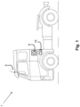
- Fig. 1 is a schematic drawing illustrating a vehicle 1 seen from the side.
- the vehicle 1 may be a heavy-duty vehicle, such as truck, bus and construction equipment, working machine, but also a car.
- the invention may be used in in any type of working machines within the fields of industrial construction machines or construction equipment, e.g. wheel loaders, articulated haulers, dump trucks, excavators and backhoe loaders etc.
- the vehicle 1 is adapted to operate in autonomous mode, i.e. it has autonomous driving capability.
- the vehicle 1 comprises a control unit 10.
- the control unit 10 is adapted to handle safe stop mode of the vehicle 1, e.g. by activating and inactivating the safe stop mode. Activating the safe stop mode may be described as enabling the safe stop mode, and inactivating the safe stop mode may be described as disabling the safe stop mode.
- the vehicle 1 does not perform autonomous driving. In other words, when the safe stop mode is activated, the vehicle 1 will not un-intentionally execute a mission and drive away creating a hazardous situation for the user.
- the autonomous mode is enabled as the same time as the safe stop mode is activated, but the vehicle 1 will not perform autonomous driving since the safe stop mode is activated.
- the autonomous mode can be disabled when the safe stop mode is activated.
- the control unit 10 may be located in any suitable location of the vehicle 1, for example in the cab, in the luggage compartment etc.
- the control unit 10 may be a Programmable Logic Controller (PLC), a safety PLC etc.
- PLC Programmable Logic Controller
- the control unit 10 may be a safety classified unit, which is different from the autonomous driving system of the vehicle 1 which is not safety classified.
- the vehicle 1 comprises at least one light source 5 adapted to emit light, it is "on", when triggered by the control unit 10.
- the at least one light source 5 is located on the outside of the vehicle 1, e.g. on the cab roof as exemplified in fig. 1 , on the front part of the vehicle 1, on the back of the vehicle 1, inside the vehicle 1 etc.
- the at least one light source 5 When the at least one light source 5 emits light, it is “on”, it may indicate that it is safe to approach the vehicle 1, meaning that the vehicle 1 is in safe stop mode and will not perform any autonomous driving while the at least one light source 5 is on. When the at least one light source 5 does not emit light, it is “off”, it may indicate that the safe stop mode is inactive and the vehicle 1 may perform autonomous driving.
- the at least one light source 5 may emit light in one or more suitable colours, e.g., green, red, yellow, orange etc.
- suitable colours e.g., green, red, yellow, orange etc.
- a first colour e.g. green
- a second colour e.g. red
- the safe stop mode is inactive and that it is not safe to exit or approach the vehicle since the vehicle 1 may perform autonomous driving.
- the at least one light source 5 may emit light in a constant fashion or it may emit light in pulses etc.
- the vehicle 1 comprises an outside input device 8 located on the outside of the vehicle 1.
- the outside input device 8 is adapted to receive input, e.g. from a user or from another device or unit comprised in the vehicle 1.
- the input device 8 may be in the form of a switch (hardware or software switch), a button, a key, a lever etc.
- the outside input device 8 is adapted to be activated for example by a user. Activating the outside input device 8 may comprise receiving input from the user, where the input may be in the form of that the user presses the outside input device 8, that the user provides a command to the input device 8.
- the outside input device 8 may be located at any suitable location on the outside of the vehicle 1 and where it is accessible to the user, for example on the side of the cab.
- the outside input device 8 is adapted to communicate with the control unit 10 via a wired or wireless link.
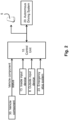
- fig. 2 is a schematic diagram illustrating the control unit 10 and other units in the vehicle 1.
- the vehicle 1 comprises an inside input device 13 located inside the vehicle 1.
- Activating the inside input device 13 may comprise receiving input from the user, where the input may be in the form of that the user presses the input device 8, that the user provides a command to the inside input device 13.
- the inside input device 13 is adapted to receive input, e.g. from a user or from another device or unit comprised in the vehicle 1.
- the inside input device 13 may be in the form of a switch (hardware or software switch), a button, a key, a lever, etc.
- the inside input device 13 may be a manually operable switch located within the cab of the vehicle 1. The inside input device 13 is adapted to be activated for example by a user.
- the inside input device 13 may be located at any suitable location on the inside of the vehicle 1 and where it is accessible to the user, for example on a display inside the cab, on the dashboard inside the cab etc.
- the inside input device 13 is adapted to communicate with the control unit 10 via a wired or wireless link.
- the vehicle 1 comprises two input devices, an inside input device 13 and an outside input device 8.
- the vehicle 1 comprises an autonomous system 20 which is adapted to control the vehicle 1 when it is in autonomous mode.
- the autonomous system 20 and the control unit 10 are adapted to communicate with each other, e.g. via a wired or wireless link, and adapted to function in parallel with each other.
- the autonomous system 20 and the control unit 10 are separate units.
- the autonomous system 20 may be referred to as an autonomous driving system.
- the vehicle 1 comprises vehicle components 30 such as brakes, parking brake, gear box, motor, communication links, etc.
- Information indicating status of one or more vehicle components 30 may be provided to the control unit 10, directly from the vehicle components 30 or via some intermediate unit.
- the intermediate unit may be an Engine Control Unit (ECU), e.g. a BodyBuilderControl ECU.
- ECU Engine Control Unit
- the information indicating the status may indicate for example that the parking brake is applied, that the gear box is in neutral gear, that a parking brake release inhibiting function of the vehicle 1 is active, that a vehicle motor is off, that vehicle brakes are applied etc.
- the vehicle components 30 may be updated to be controlled by and to communicate with the control unit 10 and the autonomous system 20.
- the vehicle 1 may comprise an emergency stop system 23 which may be adapted to communicate with the control unit 10, and possibly also the autonomous system 20.
- the emergency stop system 23 may be adapted to slow down the vehicle 1, or brake to a complete stop, for example if the vehicle 1 is about to crash into another vehicle or an obstacle.
- control unit 10 may be separate from and functioning in parallel with the autonomous system 20 of the vehicle 1.
- the method comprises at least one of the following steps, which steps may as well be carried out in another suitable order than described below:
- the control unit 10 obtains an activation request for activating, e.g. enabling, the safe stop mode. As mentioned above, the vehicle 1 cannot perform autonomous driving when the safe stop mode is activated.
- the input to the inside input device 13 is the activation request obtained from the user.
- the activation request may be an activation command, activation instructions, enabling command, enabling instructions etc.
- the activation request may be obtained from at least one of:
- the control unit 10 verifies that all safety conditions of the vehicle 1 are fulfilled.
- the fulfilled safety conditions indicate that the vehicle 1 cannot drive, i.e. it will not move.
- all safety conditions are met, the vehicle 1 is considered to not be able to move and therefore considered safe.
- control unit 10 may obtain, regularly, upon request, or continuously, status signals for one or more vehicle components associated with vehicle safety.
- vehicle components may be for example a parking brake, gearbox, motor etc.
- all safety conditions There may be one, two or more safety conditions of the vehicle 1 that may be fulfilled.
- all safety conditions comprises that one, two or more safety conditions are fulfilled.
- the safety condition may be fulfilled when at least one of:
- the vehicle 1 may be associated with a number of safety conditions.
- the number of safety conditions may be any suitable number, e.g. one, two or more safety conditions. For example, if vehicle 1 is associated with two of the safety conditions in the non-exhaustive list above, then all safety conditions may be considered fulfilled when these two are fulfilled. In another example, if the vehicle is associated with five of the safety conditions in the non-exhaustive list above, then all safety conditions may be considered fulfilled when the five safety conditions are fulfilled. In a further example, if the vehicle 1 is associated with one of the safety conditions in the non-exhaustive list above, then all safety conditions may be considered fulfilled when the one safety condition is fulfilled.
- safety conditions There may be one, two, three, more safety conditions that needs to be fulfilled. A subset of the safety conditions or all safety conditions may need to be fulfilled.
- the control unit 10 activates the safe stop mode when the activation request has been obtained and when all safety conditions are fulfilled.
- control unit 10 When the control unit 10 activates the safe stop mode, it triggers at least to disconnect communication between the vehicle 1 and an autonomous system 20 comprised in the vehicle, and in addition might trigger one or more of:
- the control unit 101 may request immobilization of the vehicle 1 by e.g. the Parking brake release inhibit function of disconnection of input devices while monitoring safety conditions such as Neutral gear engaged, Parking brake applied and ParkingBrakeReleaselnhibit Active.
- the safe stop mode When the safe stop mode has been activated in step 303, it is safe for the user to step out of the vehicle 1 since it the safe stop mode ensures that the vehicle 1 will not perform autonomous driving. Also, it will be safe for a user to approach the vehicle 1 when it is in safe stop mode.
- the control unit 10 may provide, to the autonomous system 20 of the vehicle 1, information indicating whether the safe stop mode is activated or inactivated, e.g. enabled or disabled. This step 204 may be performed after step 301, 302 or 303 in case of activation of the safe stop mode, and after step 305, 306, 307 or 308 in case of inactivating of the safe stop mode.
- the control unit 10 triggers at least one light source 5 to be turned on or to emit light of a first colour, e.g. green, when all safety conditions are fulfilled.
- a first colour e.g. green
- the user when he is inside the vehicle 1 and the safe stop mode has been activated, knows that it is safe to exit the vehicle 1 when the at least one light source 5 is turned on or emits a light of the first colour. If there is at least one light source 5 on the outside of the vehicle 1, then the user, when he is outside the vehicle 1 and wants to approach it, knows that it is safe to approach it when the light source is turned on or emits a light of the first colour.
- the triggering of the at least one light source 5 may be described as a confirmation of that the safe stop mode has been activated, and possibly also that the autonomous driving will not take place.
- the control unit 10 obtains an inactivation request, e.g. disabling request, for inactivating the safe stop mode of the vehicle 1.
- the input to the inside input device 13 and the outside input device 8 is the inactivation request obtained from the user.
- the inactivation request may be an inactivation command, inactivation instructions, disabling command, disabling instructions etc.
- the inactivation request is obtained at least from the outside input device 8 being activated by a user and might additionally be obtained from the inside input device 13 being activated by the user.
- the user if the safe stop mode is activated, the user is inside the vehicle 1 and wants to take control of the vehicle 1, the user may inactivate the safe stop mode by providing the inactivating request, e.g. by activating the inside input device 13.
- the user may inactivate the safe stop mode by providing the inactivating request, e.g. by activating the outside input device 8.
- the inactivation request may be obtained by that the user performs an action, e.g. pushes the inside input device 13 or the outside input device 8.
- the control unit 10 inactivates the safe stop mode of the vehicle 1 when the inactivation request has been obtained.
- the vehicle 1 can perform autonomous driving when the safe stop mode is inactivated.
- the control unit 10 may trigger inactivation of a parking brake release inhibiting function of the vehicle 1 when the inactivation request has been obtained.
- the control unit 10 may trigger the at least one light source 5 to be turned off when the inactivation request has been obtained, or to emit a light of a second colour indicating that the safe stop mode is inactivated. This step 309 may be performed after step 306, 307 or 308.
- the computer program comprising instructions, i.e., software code portions, which, when executed on at least one processor, cause the at least one processor to carry out the method described herein, as performed by the control unit 10.
- the computer program may be stored on a computer-readable storage medium.
- the computer-readable storage medium having stored thereon the computer program, may comprise instructions which, when executed on at least one processor, cause the at least one processor to carry out the actions described herein, as performed by the control unit 10.
- the computer-readable storage medium may be a non-transitory computer-readable storage medium, such as a CD ROM disc or a memory stick.
- the computer program product may be stored on a carrier containing the computer program just described, wherein the carrier is one of an electronic signal, optical signal, radio signal, or the computer-readable storage medium, as described above.
- the control unit 10 may comprise a communication interface configured to facilitate communications between the control unit 10 and other units or components, e.g., the ECU, the autonomous system 20, or another structure.
- the interface may comprise a transceiver configured to transmit and receive signals over a wired or wireless interface in accordance with a suitable standard.
- the control unit 10 is configured to perform the method as described herein.
- the method for handling safe stop mode of a vehicle 1 described herein may be implemented through one or more processors, such as a processor in the control unit 10, together with computer program code for performing the method described herein.
- the processor may be for example a Digital Signal Processor (DSP), Application Specific Integrated Circuit (ASIC) processor, Field-programmable gate array (FPGA) processor or microprocessor.
- DSP Digital Signal Processor
- ASIC Application Specific Integrated Circuit
- FPGA Field-programmable gate array
- the program code mentioned above may also be provided as a computer program product, for instance in the form of a data carrier carrying computer program code for performing the present invention herein when being loaded into the control unit 10.
- One such carrier may be in the form of a CD ROM disc. It is however feasible with other data carriers such as a memory stick.
- the computer program code can be provided as pure program code on a server and downloaded to the control unit 10.
- the control unit 10 may comprise a memory comprising one or more memory units.
- the memory is arranged to be used to store information, status, mode information, requests, schedulings, and applications etc. to perform the methods herein when being executed in control unit 10.
- a control system may comprise the control unit 10 as described herein, at least one light source 5 and at least one input device 8, 13.
- a vehicle 1 comprises the control unit 10 as described herein.
- Fig. 4 is a schematic block diagram illustrating an example of the control unit 10.
- Fig. 4 shows that the safety conditions may be parking break release inhibit status, neutral gear status and parking break status. Note that the safety conditions are not limited to the ones illustrated in fig.4 , and also not limited to the number of safety conditions illustrated in fig. 4 .
- the status of the safety conditions may be obtained by the control unit 10.
- the &-symbol in fig. 4 illustrates that all safety conditions are fulfilled.
- the safe stop mode is activated.
- the at least one light source 5 is triggered to emit light.
- the status of the safe stop mode may be provided to the autonomous system 20.
- the example of fig. 4 shows that the inactivation request is obtained, e.g. a user disable command is obtained or set.
- the control unit 10 may trigger setting of the parking break release inhibiting function or any other suitable function that, when set, guarantees that the vehicle 1 will remain standstill, i.e. that it will not drive autonomously,
- Fig. 4 shows inactivation and activation of the safe stop mode.
- the control unit 10 resets the safe stop mode. Resetting the safe stop mode may be the same as activating the safe stop mode. Activated safe stop mode may be a default situation.
- Fig. 4 also illustrates that the inactivation request is set.
- the inactivation request may be a user disable command.
- the term SR flip-flop in fig. 4 represents Set-Reset flip-flop.
- the activation request may be a user enable command.
- Vehicle motion inhibit instructions may be provided as input to setting of the parking break release inhibiting function.
- the safe stop mode guarantees that the vehicle 1 is safe to approach or leave, even if the vehicle 1 is in autonomous mode.
- the vehicle 1 is considered safe if it cannot move.
- one or more safety conditions need to be fulfilled.
- the fulfilled safety conditions may be for example that the parking brake is applied, the gearbox is in neutral gear and a specific parking brake release inhibiting function is active that prevents the parking brake from being released.
- Status signals which indicate the safety conditions may be available directly from the vehicle components 30 or from an ECU in the vehicle 1.
- One way of monitoring the safety conditions instead of relying on an ECU may be to use safety classified sensors to directly monitor the status.
- E.g. pressure sensor in the parking brake circuit. Possibly also a double sensor for redundancy and increasing the integrity level may be utilized.
- the control unit 10 verifies the safety conditions and turns at least one light source 5, e.g. a green light, for the user meaning that the "Vehicle is in Safe Stop Mode".
- at least one light source 5 e.g. a green light
- the safe stop mode may be requested from several sources; the autonomous system 20 itself, the emergency stop system 23 or the user through an input device, e.g. the inside input device 13.
- a request to activate the ParkingBrakeReleaselnhibiting function may be triggered.
- the ParkingBrakeReleaselnhibiting function may be a separate unit adapted to communicate with the control unit 10 or it may be comprised in the in the BodyBuilderControl ECU.
- the vehicle 1 may be different ways of guarantee that the vehicle 1 will remain standstill, i.e. that it will not drive autonomously, such as actively apply parking brake, e.g. purging the parking brake air circuit with solenoids, disconnect the communication from the autonomous system 20 to the vehicle base.
- actively apply parking brake e.g. purging the parking brake air circuit with solenoids
- the safe stop mode When the safe stop mode is activated, the user can safely leave the vehicle 1.
- One way to inactivate the safe stop mode may be by pressing another input device, e.g. the outside input device 8. Once stepped out, the user may now safely inactivate the sate stop mode and the vehicle 1 may enter autonomous mode fully and start to execute an autonomous mission.
- a request to activate the safe stop mode may be sent remotely, the at least one light source 5 may be lit and the user thereby knows that the vehicle 1 is safe to approach. Once inside the vehicle 1, the user may inactivate the safe stop mode again using another input device, and take control of the vehicle 1.
- the safe stop mode may be requested by the emergency stop system 23.
- the status of the safe stop mode may be sent to the autonomous system 20.
- a vehicle motion manager function may react and prevent requests for motion to be executed.
- the vehicle motion manager function may be a function comprised in the autonomous system i.e. a unit that may have at least partly control of the vehicle 1.
- a and B should be understood to mean “only A, only B, or both A and B.”, where A and B are any parameter, number, indication used herein etc.
Landscapes
- Engineering & Computer Science (AREA)
- Mechanical Engineering (AREA)
- Automation & Control Theory (AREA)
- Transportation (AREA)
- Human Computer Interaction (AREA)
- Control Of Driving Devices And Active Controlling Of Vehicle (AREA)
- Traffic Control Systems (AREA)
Description
- The invention relates generally to a method, a program, a storage, and a control unit.
- More particularly the invention relates to handling safe stop mode of the vehicle.
- The invention can be applied in heavy-duty vehicles, such as trucks, buses and construction equipment, and which are adapted to operate in autonomous mode.
- Although the invention will be described with respect to a truck, the invention is not restricted to this particular vehicle, but may also be used in other vehicles such as buses, construction equipment, trucks, working machines, cars. The invention may be used in in any type of working machine within the fields of industrial construction machines or construction equipment, e.g. wheel loaders, articulated haulers, dump trucks, excavators and backhoe loaders etc.
- An autonomous mode is today available in many vehicles. When a vehicle is in autonomous mode, it may be referred to as an autonomous vehicle or a self-driving vehicle. When a vehicle is in autonomous mode, it may for example accelerate, brake and steer itself. Further, in autonomous mode, the vehicle may sense its environment and navigate safely without human input or external control.
- There are several levels of the autonomous mode in a vehicle which is in the range from no automation, via partial autonomous and up to fully autonomous. For example, when a vehicle is in an autonomous mode, some or all driving aspects of vehicle operation can be handled by a vehicle control system. In such cases, computing devices comprised onboard the vehicle and in a server network may be operable to carry out functions such as planning a driving route, sensing aspects of the vehicle, sensing the environment of the vehicle, and controlling drive functions such as steering, accelerating and braking. Thus, a vehicle in autonomous mode may reduce or eliminate the need for human interaction in various aspects of vehicle operation. A fully autonomous vehicle is able to perform all driving functions without supervision of a user and any external control.
-
- When a user wants to enable autonomous mode in a vehicle, the start-up procedure is typically initiated by the user from within the vehicle cab. The autonomous part of the vehicle needs to be powered up, computers and sensors need to be activated, some self-diagnostics has to be performed and communication with an external control system, e.g. a site control system, has to be established. Since the user then needs to leave the vehicle, it is very important that this is done in a safe way. It is necessary to guarantee that the autonomous vehicle will not start to un-intentionally execute a mission and drive away creating a hazardous situation for the user. The same need occurs when a human needs to approach a vehicle that is in autonomous mode for e.g. picking it up or handle unplanned stops.
- Therefore, there is a need to at least mitigate or solve the above issues.
- An object of the invention is to provide improved safety for a vehicle adapted to operate in autonomous mode.
- The invention is defined by the independent claims.
- The present invention affords many advantages, of which a non-exhaustive list follows:
Since the safe stop mode is activated when all safety conditions are fulfilled, it is ensured that the vehicle cannot perform autonomous driving. The safety conditions may be that the parking brake is applied, that the gear box is in neutral gear etc., which are conditions that, when fulfilled, prevents the vehicle from performing autonomous driving. When the safe stop mode is activated based on e.g. that a user inside the vehicle activates an inside input device, the vehicle is considered safe since it cannot move. Thus, the user can safely go out of the vehicle knowing that the vehicle will not perform autonomous driving, e.g. the vehicle will not move while he exits the vehicle. - With the triggering of the light source, the user and any other persons surrounding the vehicle will understand that the safe stop mode is activated and that it is safe to exit and approach the vehicle without any risk for the vehicle performing unintentional autonomous driving. In other words, the light source indicates that the vehicle will not un-intentionally execute a mission and drive away creating a hazardous situation for the user.
- With the possibility to inactivate the safe stop mode and thereby activate autonomous driving, e.g. by activation of an outside input device, it ensures that autonomous driving cannot be reactivated until the user is outside of the vehicle. Thus, safety is improved.
- According to a second aspect, the object is achieved by a control unit configured to perform the method of
claim 1. - Effects and features of the second aspect are largely analogous to those described above in connection with the first aspect.
- Further advantages and advantageous features of the invention are disclosed in the following description and in the dependent claims.
- With reference to the appended drawings, below follows a more detailed description of embodiments of the invention cited as examples.
- In the drawings:
- Fig. 1
- is a schematic drawing of a vehicle.
- Fig. 2
- is a schematic block diagram illustrating a control unit.
- Fig. 3
- is a flow chart illustrating a method.
- Fig. 4
- is a schematic block diagram illustrating a control unit.
- The drawings are not necessarily to scale and the dimensions of certain features may have been exaggerated for the sake of clarity. Emphasis is instead placed upon illustrating principles.
-
Fig. 1 is a schematic drawing illustrating avehicle 1 seen from the side. As mentioned above, thevehicle 1 may be a heavy-duty vehicle, such as truck, bus and construction equipment, working machine, but also a car. The invention may be used in in any type of working machines within the fields of industrial construction machines or construction equipment, e.g. wheel loaders, articulated haulers, dump trucks, excavators and backhoe loaders etc. Thevehicle 1 is adapted to operate in autonomous mode, i.e. it has autonomous driving capability. - The
vehicle 1 comprises acontrol unit 10. Thecontrol unit 10 is adapted to handle safe stop mode of thevehicle 1, e.g. by activating and inactivating the safe stop mode. Activating the safe stop mode may be described as enabling the safe stop mode, and inactivating the safe stop mode may be described as disabling the safe stop mode. When the safe stop mode is activated, thevehicle 1 does not perform autonomous driving. In other words, when the safe stop mode is activated, thevehicle 1 will not un-intentionally execute a mission and drive away creating a hazardous situation for the user. The autonomous mode is enabled as the same time as the safe stop mode is activated, but thevehicle 1 will not perform autonomous driving since the safe stop mode is activated. The autonomous mode can be disabled when the safe stop mode is activated. - The
control unit 10 may be located in any suitable location of thevehicle 1, for example in the cab, in the luggage compartment etc. Thecontrol unit 10 may be a Programmable Logic Controller (PLC), a safety PLC etc. Thecontrol unit 10 may be a safety classified unit, which is different from the autonomous driving system of thevehicle 1 which is not safety classified. - The
vehicle 1 comprises at least onelight source 5 adapted to emit light, it is "on", when triggered by thecontrol unit 10. The at least onelight source 5 is located on the outside of thevehicle 1, e.g. on the cab roof as exemplified infig. 1 , on the front part of thevehicle 1, on the back of thevehicle 1, inside thevehicle 1 etc. There may be one, two or morelight sources 5 comprised in thevehicle 1, for example twolight sources 5 on the cab roof and one inside the cab, or onelight source 5 on the cab roof and one inside the cab, only onelight source 5 in the cab etc. - When the at least one
light source 5 emits light, it is "on", it may indicate that it is safe to approach thevehicle 1, meaning that thevehicle 1 is in safe stop mode and will not perform any autonomous driving while the at least onelight source 5 is on. When the at least onelight source 5 does not emit light, it is "off", it may indicate that the safe stop mode is inactive and thevehicle 1 may perform autonomous driving. - The at least one
light source 5 may emit light in one or more suitable colours, e.g., green, red, yellow, orange etc. For example, when the at least onelight source 5 emits light in a first colour, e.g. green, it may indicate that safe stop mode is activated and that it is safe to exit or approach thevehicle 1. When the at least onelight source 5 emits light in a second colour, e.g. red, it may indicate that the safe stop mode is inactive and that it is not safe to exit or approach the vehicle since thevehicle 1 may perform autonomous driving. - The at least one
light source 5 may emit light in a constant fashion or it may emit light in pulses etc. - The
vehicle 1 comprises anoutside input device 8 located on the outside of thevehicle 1. Theoutside input device 8 is adapted to receive input, e.g. from a user or from another device or unit comprised in thevehicle 1. Theinput device 8 may be in the form of a switch (hardware or software switch), a button, a key, a lever etc. Theoutside input device 8 is adapted to be activated for example by a user. Activating theoutside input device 8 may comprise receiving input from the user, where the input may be in the form of that the user presses theoutside input device 8, that the user provides a command to theinput device 8. Theoutside input device 8 may be located at any suitable location on the outside of thevehicle 1 and where it is accessible to the user, for example on the side of the cab. Theoutside input device 8 is adapted to communicate with thecontrol unit 10 via a wired or wireless link. - Now turning to
fig. 2 which provides more details regarding thecontrol unit 10 compared tofig. 1 . In addition to the units described above with reference tofig. 1 , thevehicle 10 comprises one or more of the units illustrated infig. 2. Fig. 2 is a schematic diagram illustrating thecontrol unit 10 and other units in thevehicle 1. - As seen in
fig. 2 , thevehicle 1 comprises aninside input device 13 located inside thevehicle 1. Activating theinside input device 13 may comprise receiving input from the user, where the input may be in the form of that the user presses theinput device 8, that the user provides a command to theinside input device 13. Theinside input device 13 is adapted to receive input, e.g. from a user or from another device or unit comprised in thevehicle 1. Theinside input device 13 may be in the form of a switch (hardware or software switch), a button, a key, a lever, etc. Theinside input device 13 may be a manually operable switch located within the cab of the vehicle 1.Theinside input device 13 is adapted to be activated for example by a user. Theinside input device 13 may be located at any suitable location on the inside of thevehicle 1 and where it is accessible to the user, for example on a display inside the cab, on the dashboard inside the cab etc. Theinside input device 13 is adapted to communicate with thecontrol unit 10 via a wired or wireless link. Thus, thevehicle 1 comprises two input devices, aninside input device 13 and anoutside input device 8. - The
vehicle 1 comprises an autonomous system 20 which is adapted to control thevehicle 1 when it is in autonomous mode. The autonomous system 20 and thecontrol unit 10 are adapted to communicate with each other, e.g. via a wired or wireless link, and adapted to function in parallel with each other. Thus, the autonomous system 20 and thecontrol unit 10 are separate units. The autonomous system 20 may be referred to as an autonomous driving system. - The
vehicle 1 comprisesvehicle components 30 such as brakes, parking brake, gear box, motor, communication links, etc. Information indicating status of one ormore vehicle components 30 may be provided to thecontrol unit 10, directly from thevehicle components 30 or via some intermediate unit. The intermediate unit may be an Engine Control Unit (ECU), e.g. a BodyBuilderControl ECU. The information indicating the status may indicate for example that the parking brake is applied, that the gear box is in neutral gear, that a parking brake release inhibiting function of thevehicle 1 is active, that a vehicle motor is off, that vehicle brakes are applied etc. Thevehicle components 30 may be updated to be controlled by and to communicate with thecontrol unit 10 and the autonomous system 20. - The
vehicle 1 may comprise anemergency stop system 23 which may be adapted to communicate with thecontrol unit 10, and possibly also the autonomous system 20. Theemergency stop system 23 may be adapted to slow down thevehicle 1, or brake to a complete stop, for example if thevehicle 1 is about to crash into another vehicle or an obstacle. - The method for handling safe stop mode of a
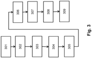
vehicle 1 performed by thecontrol unit 10 will now be described with reference to the flowchart depicted infig. 3 . As mentioned above thecontrol unit 10 may be separate from and functioning in parallel with the autonomous system 20 of thevehicle 1. The method comprises at least one of the following steps, which steps may as well be carried out in another suitable order than described below: - The
control unit 10 obtains an activation request for activating, e.g. enabling, the safe stop mode. As mentioned above, thevehicle 1 cannot perform autonomous driving when the safe stop mode is activated. - The input to the
inside input device 13 is the activation request obtained from the user. The activation request may be an activation command, activation instructions, enabling command, enabling instructions etc. - The activation request may be obtained from at least one of:
- the autonomous system 20 comprised in the
vehicle 1, - an
emergency stop system 23 comprised in thevehicle 1, and - the
inside input device 13 being activated by a user. - When the activation request has been obtained, the
control unit 10 verifies that all safety conditions of thevehicle 1 are fulfilled. The fulfilled safety conditions indicate that thevehicle 1 cannot drive, i.e. it will not move. When all safety conditions are met, thevehicle 1 is considered to not be able to move and therefore considered safe. - In order to be able to verify fulfilment of all safety conditions, the
control unit 10 may obtain, regularly, upon request, or continuously, status signals for one or more vehicle components associated with vehicle safety. The vehicle components may be for example a parking brake, gearbox, motor etc. - There may be one, two or more safety conditions of the
vehicle 1 that may be fulfilled. Thus, the term "all" in "all safety conditions" comprises that one, two or more safety conditions are fulfilled. Below is a non-exhaustive list of fulfilled safety conditions, and one, two or more of these may be fulfilled when all safety conditions are deemed to be fulfilled. - The safety condition may be fulfilled when at least one of:
- a parking brake 25 of the
vehicle 1 is applied, - a gearbox of the
vehicle 1 is in neutral gear, - a parking brake release inhibiting function of the
vehicle 1 is active, - a vehicle motor is off;
- at least one vehicle brake is applied.
- As mentioned above, the list is non-exhaustive which implies that there may be additional safety conditions that are applicable, but not mentioned herein.
- Summarized, the
vehicle 1 may be associated with a number of safety conditions. The number of safety conditions may be any suitable number, e.g. one, two or more safety conditions. For example, ifvehicle 1 is associated with two of the safety conditions in the non-exhaustive list above, then all safety conditions may be considered fulfilled when these two are fulfilled. In another example, if the vehicle is associated with five of the safety conditions in the non-exhaustive list above, then all safety conditions may be considered fulfilled when the five safety conditions are fulfilled. In a further example, if thevehicle 1 is associated with one of the safety conditions in the non-exhaustive list above, then all safety conditions may be considered fulfilled when the one safety condition is fulfilled. - There may be one, two, three, more safety conditions that needs to be fulfilled. A subset of the safety conditions or all safety conditions may need to be fulfilled.
- The
control unit 10 activates the safe stop mode when the activation request has been obtained and when all safety conditions are fulfilled. - When the
control unit 10 activates the safe stop mode, it triggers at least to disconnect communication between thevehicle 1 and an autonomous system 20 comprised in the vehicle, and in addition might trigger one or more of: - activation of a parking brake release inhibiting function of the
vehicle 1; - application of vehicle brakes; and
- force neutral gear.
- In
step 303, the control unit 101 may request immobilization of thevehicle 1 by e.g. the Parking brake release inhibit function of disconnection of input devices while monitoring safety conditions such as Neutral gear engaged, Parking brake applied and ParkingBrakeReleaselnhibit Active. - When the safe stop mode has been activated in
step 303, it is safe for the user to step out of thevehicle 1 since it the safe stop mode ensures that thevehicle 1 will not perform autonomous driving. Also, it will be safe for a user to approach thevehicle 1 when it is in safe stop mode. - The
control unit 10 may provide, to the autonomous system 20 of thevehicle 1, information indicating whether the safe stop mode is activated or inactivated, e.g. enabled or disabled. This step 204 may be performed afterstep step - The
control unit 10 triggers at least onelight source 5 to be turned on or to emit light of a first colour, e.g. green, when all safety conditions are fulfilled. - If there is at least one
light source 5 inside thevehicle 1, then the user, when he is inside thevehicle 1 and the safe stop mode has been activated, knows that it is safe to exit thevehicle 1 when the at least onelight source 5 is turned on or emits a light of the first colour. If there is at least onelight source 5 on the outside of thevehicle 1, then the user, when he is outside thevehicle 1 and wants to approach it, knows that it is safe to approach it when the light source is turned on or emits a light of the first colour. - The triggering of the at least one
light source 5 may be described as a confirmation of that the safe stop mode has been activated, and possibly also that the autonomous driving will not take place. - After the safe stop mode has been activated, the
control unit 10 obtains an inactivation request, e.g. disabling request, for inactivating the safe stop mode of thevehicle 1. The input to theinside input device 13 and theoutside input device 8 is the inactivation request obtained from the user. The inactivation request may be an inactivation command, inactivation instructions, disabling command, disabling instructions etc. - The inactivation request is obtained at least from the
outside input device 8 being activated by a user and might additionally be obtained from theinside input device 13 being activated by the user. - According to an example outside the protection scope of the invention, if the safe stop mode is activated, the user is inside the
vehicle 1 and wants to take control of thevehicle 1, the user may inactivate the safe stop mode by providing the inactivating request, e.g. by activating theinside input device 13. - According to the invention, if the safe stop mode is activated, the user is outside the
vehicle 1 and wants to activate autonomous driving, the user may inactivate the safe stop mode by providing the inactivating request, e.g. by activating theoutside input device 8. - The inactivation request may be obtained by that the user performs an action, e.g. pushes the
inside input device 13 or theoutside input device 8. - The
control unit 10 inactivates the safe stop mode of thevehicle 1 when the inactivation request has been obtained. Thevehicle 1 can perform autonomous driving when the safe stop mode is inactivated. - The
control unit 10 may trigger inactivation of a parking brake release inhibiting function of thevehicle 1 when the inactivation request has been obtained. - The
control unit 10 may trigger the at least onelight source 5 to be turned off when the inactivation request has been obtained, or to emit a light of a second colour indicating that the safe stop mode is inactivated. Thisstep 309 may be performed afterstep - The computer program, comprising instructions, i.e., software code portions, which, when executed on at least one processor, cause the at least one processor to carry out the method described herein, as performed by the
control unit 10. The computer program may be stored on a computer-readable storage medium. The computer-readable storage medium, having stored thereon the computer program, may comprise instructions which, when executed on at least one processor, cause the at least one processor to carry out the actions described herein, as performed by thecontrol unit 10. The computer-readable storage medium may be a non-transitory computer-readable storage medium, such as a CD ROM disc or a memory stick. The computer program product may be stored on a carrier containing the computer program just described, wherein the carrier is one of an electronic signal, optical signal, radio signal, or the computer-readable storage medium, as described above. - The
control unit 10 may comprise a communication interface configured to facilitate communications between thecontrol unit 10 and other units or components, e.g., the ECU, the autonomous system 20, or another structure. The interface may comprise a transceiver configured to transmit and receive signals over a wired or wireless interface in accordance with a suitable standard. - The
control unit 10 is configured to perform the method as described herein. - The method for handling safe stop mode of a
vehicle 1 described herein may be implemented through one or more processors, such as a processor in thecontrol unit 10, together with computer program code for performing the method described herein. The processor may be for example a Digital Signal Processor (DSP), Application Specific Integrated Circuit (ASIC) processor, Field-programmable gate array (FPGA) processor or microprocessor. The program code mentioned above may also be provided as a computer program product, for instance in the form of a data carrier carrying computer program code for performing the present invention herein when being loaded into thecontrol unit 10. One such carrier may be in the form of a CD ROM disc. It is however feasible with other data carriers such as a memory stick. The computer program code can be provided as pure program code on a server and downloaded to thecontrol unit 10. - The
control unit 10 may comprise a memory comprising one or more memory units. The memory is arranged to be used to store information, status, mode information, requests, schedulings, and applications etc. to perform the methods herein when being executed incontrol unit 10. - A control system may comprise the
control unit 10 as described herein, at least onelight source 5 and at least oneinput device - A
vehicle 1 comprises thecontrol unit 10 as described herein. -
Fig. 4 is a schematic block diagram illustrating an example of thecontrol unit 10.Fig. 4 shows that the safety conditions may be parking break release inhibit status, neutral gear status and parking break status. Note that the safety conditions are not limited to the ones illustrated infig.4 , and also not limited to the number of safety conditions illustrated infig. 4 . The status of the safety conditions may be obtained by thecontrol unit 10. The &-symbol infig. 4 illustrates that all safety conditions are fulfilled. When the safety conditions are fulfilled, the safe stop mode is activated. Then, the at least onelight source 5 is triggered to emit light. The status of the safe stop mode may be provided to the autonomous system 20. - The example of
fig. 4 shows that the inactivation request is obtained, e.g. a user disable command is obtained or set. When it is set, thecontrol unit 10 may trigger setting of the parking break release inhibiting function or any other suitable function that, when set, guarantees that thevehicle 1 will remain standstill, i.e. that it will not drive autonomously, -
Fig. 4 shows inactivation and activation of the safe stop mode. When the emergency stop system is stopped, the autonomous driving system is of a certain status and the activation request is obtained, indicated by being larger or equal to 1 infig. 4 , thecontrol unit 10 resets the safe stop mode. Resetting the safe stop mode may be the same as activating the safe stop mode. Activated safe stop mode may be a default situation.Fig. 4 also illustrates that the inactivation request is set. The inactivation request may be a user disable command. The term SR flip-flop infig. 4 represents Set-Reset flip-flop. The activation request may be a user enable command. Vehicle motion inhibit instructions may be provided as input to setting of the parking break release inhibiting function. - Some embodiments may be summarized as follows:
The safe stop mode guarantees that thevehicle 1 is safe to approach or leave, even if thevehicle 1 is in autonomous mode. - The
vehicle 1 is considered safe if it cannot move. To guarantee it to be safe, one or more safety conditions need to be fulfilled. The fulfilled safety conditions may be for example that the parking brake is applied, the gearbox is in neutral gear and a specific parking brake release inhibiting function is active that prevents the parking brake from being released. - Status signals which indicate the safety conditions may be available directly from the
vehicle components 30 or from an ECU in thevehicle 1. One way of monitoring the safety conditions instead of relying on an ECU may be to use safety classified sensors to directly monitor the status. E.g. pressure sensor in the parking brake circuit. Possibly also a double sensor for redundancy and increasing the integrity level may be utilized. - The
control unit 10 verifies the safety conditions and turns at least onelight source 5, e.g. a green light, for the user meaning that the "Vehicle is in Safe Stop Mode". - The safe stop mode may be requested from several sources; the autonomous system 20 itself, the
emergency stop system 23 or the user through an input device, e.g. theinside input device 13. When safe mode is requested, a request to activate the ParkingBrakeReleaselnhibiting function may be triggered. The ParkingBrakeReleaselnhibiting function may be a separate unit adapted to communicate with thecontrol unit 10 or it may be comprised in the in the BodyBuilderControl ECU. - There may be different ways of guarantee that the
vehicle 1 will remain standstill, i.e. that it will not drive autonomously, such as actively apply parking brake, e.g. purging the parking brake air circuit with solenoids, disconnect the communication from the autonomous system 20 to the vehicle base. - When the safe stop mode is activated, the user can safely leave the
vehicle 1. One way to inactivate the safe stop mode may be by pressing another input device, e.g. theoutside input device 8. Once stepped out, the user may now safely inactivate the sate stop mode and thevehicle 1 may enter autonomous mode fully and start to execute an autonomous mission. - If a user wants to approach the
vehicle 1 when it drives autonomously, a request to activate the safe stop mode may be sent remotely, the at least onelight source 5 may be lit and the user thereby knows that thevehicle 1 is safe to approach. Once inside thevehicle 1, the user may inactivate the safe stop mode again using another input device, and take control of thevehicle 1. - The safe stop mode may be requested by the
emergency stop system 23. - The status of the safe stop mode may be sent to the autonomous system 20. This way a vehicle motion manager function may react and prevent requests for motion to be executed. The vehicle motion manager function may be a function comprised in the autonomous system i.e. a unit that may have at least partly control of the
vehicle 1. - The term "at least one of A and B" should be understood to mean "only A, only B, or both A and B.", where A and B are any parameter, number, indication used herein etc.
- It should be emphasized that the term "comprises/comprising" when used in this specification is taken to specify the presence of stated features, integers, steps or components, but does not preclude the presence or addition of one or more other features, integers, steps, components or groups thereof. It should also be noted that the words "a" or "an" preceding an element do not exclude the presence of a plurality of such elements.
- The term "configured to" used herein may also be referred to as "arranged to", "adapted to", "capable of" or "operative to".
- It should also be emphasised that the steps of the methods defined in the appended claims may, without departing from the embodiments herein, be performed in another order than the order in which they appear in the claims.
- It is to be understood that the present invention is not limited to the embodiments described above and illustrated in the drawings; rather, the skilled person will recognize that many changes and modifications may be made within the scope of the appended claims.
Claims (14)
- A method performed by a control unit (10) for handling safe stop mode of a vehicle (1) in autonomous mode, whereby the method comprises:obtaining (301), from an inside input device (13) being activated by a user, wherein the inside input device (13) is located inside the vehicle (1), an activation request for activating the safe stop mode, wherein the vehicle (1) cannot perform autonomous driving when the safe stop mode is activated, and wherein the autonomous mode is enabled at the same time as the safe stop mode is activated;when the activation request has been obtained, verifying (302) that all safety conditions of the vehicle (1) are fulfilled, wherein the fulfilled safety conditions indicates that the vehicle (1) cannot move;activating (303) the safe stop mode when the activation request has been obtained and when all safety conditions are fulfilled, wherein the activating (303) the safe stop mode comprises disconnection of communication between the vehicle (1) and an autonomous system (20) comprised in the vehicle;triggering (305) at least one light source (5) located on the outside of the vehicle (1) to be turned on when all safety conditions are fulfilled;after the safe stop mode has been activated, obtaining (306), from an outside input device (8) being activated by the user, an inactivation request for inactivating the safe stop mode of the vehicle (1), wherein the outside input device (8) is located on the outside of the vehicle (1); andinactivating (307) the safe stop mode of the vehicle (1) when the inactivation request has been obtained, wherein the vehicle (1) can perform autonomous driving when the safe stop mode is inactivated.
- The method according to claim 1, wherein inactivating (307) the safe stop mode comprises:
triggering (308) inactivation of a parking brake release inhibiting function of the vehicle (1) when the inactivation request has been obtained. - The method according to either of the preceding claims, wherein the activating (303) the safe stop mode comprises:
triggering (303) at least one of:• activation of a parking brake release inhibiting function of the vehicle (1);• application of vehicle brakes. - The method according to any of the preceding claims, wherein the activation request for activating the safe stop mode is obtained from at least one of:• an autonomous system (20) comprised in the vehicle (1), and• an emergency stop system (23) comprised in the vehicle (1).
- The method according to any of the preceding claims, wherein the inactivation request is obtained from:• an inside input device (13) being activated by a user, wherein the inside input device (13) is located inside the vehicle (1).
- The method according to any of the preceding claims, wherein all safety conditions are fulfilled when at least one of:• a parking brake (25) of the vehicle (1) is applied,• a gearbox of the vehicle (1) is in neutral gear,• a parking brake release inhibiting function of the vehicle (1) is active,• a vehicle motor is off;• vehicle brakes are applied.
- The method according to any of the preceding claims, comprising:
providing (304), to an autonomous driving system (20) of the vehicle (1), information indicating whether the safe stop mode is activated or inactivated. - The method according to any of the preceding claims, comprising:
triggering (309) the at least one light source (5) to be turned off when the inactivation request has been obtained. - The method according to any of the preceding claims, wherein the control unit (10) is separate from and functioning in parallel with an autonomous driving system (20) of the vehicle (1),
- A computer program comprising program code means for performing the steps of any of claims 1-9 when said program is run on a computer.
- A computer readable medium carrying a computer program comprising program code means for performing the steps of any of claims 1-9 when said program product is run on a computer.
- A control unit (10) configured to perform the method according to any one of claims 1-9.
- A control system (100) comprising the control unit (10) according to claim 12, at least one light source (5) and at least one input device (8, 13).
- A vehicle (1) comprising a control unit (10) according to claim 12.
Applications Claiming Priority (1)
| Application Number | Priority Date | Filing Date | Title |
|---|---|---|---|
| PCT/EP2020/065978 WO2021249627A1 (en) | 2020-06-09 | 2020-06-09 | Method and control unit for handling safe stop mode of a vehicle |
Publications (3)
| Publication Number | Publication Date |
|---|---|
| EP4162336A1 EP4162336A1 (en) | 2023-04-12 |
| EP4162336C0 EP4162336C0 (en) | 2024-05-15 |
| EP4162336B1 true EP4162336B1 (en) | 2024-05-15 |
Family
ID=71096682
Family Applications (1)
| Application Number | Title | Priority Date | Filing Date |
|---|---|---|---|
| EP20733225.5A Active EP4162336B1 (en) | 2020-06-09 | 2020-06-09 | Method and control unit for handling safe stop mode of a vehicle |
Country Status (5)
| Country | Link |
|---|---|
| US (1) | US12479449B2 (en) |
| EP (1) | EP4162336B1 (en) |
| CN (1) | CN116097191B (en) |
| AU (1) | AU2020452696A1 (en) |
| WO (1) | WO2021249627A1 (en) |
Families Citing this family (2)
| Publication number | Priority date | Publication date | Assignee | Title |
|---|---|---|---|---|
| KR102816375B1 (en) * | 2021-03-31 | 2025-06-05 | 히다치 겡키 가부시키 가이샤 | Construction machinery |
| DE102022204480A1 (en) | 2022-05-06 | 2023-11-09 | Zf Friedrichshafen Ag | Actuation system for a vehicle brake |
Family Cites Families (24)
| Publication number | Priority date | Publication date | Assignee | Title |
|---|---|---|---|---|
| US5204814A (en) | 1990-11-13 | 1993-04-20 | Mobot, Inc. | Autonomous lawn mower |
| CA2096497A1 (en) | 1992-05-26 | 1993-11-27 | Patricia Anne Spears | Mycobacteria probes |
| US5469356A (en) * | 1994-09-01 | 1995-11-21 | Caterpillar Inc. | System for controlling a vehicle to selectively allow operation in either an autonomous mode or a manual mode |
| JP4426737B2 (en) * | 2000-06-28 | 2010-03-03 | 東芝キヤリア株式会社 | Refrigeration equipment for vehicles |
| US6650993B2 (en) * | 2001-06-04 | 2003-11-18 | General Electric Company | Automatic start/stop system and method for locomotive engines |
| DE10210547A1 (en) * | 2002-03-09 | 2003-09-18 | Bosch Gmbh Robert | Speed controller with stop & go function |
| US9983586B2 (en) * | 2011-04-28 | 2018-05-29 | Positec Power Tools (Suzhou) Co., Ltd. | Autonomous working system, an autonomous vehicle and a turning method thereof |
| KR101484200B1 (en) * | 2013-06-12 | 2015-01-19 | 현대자동차 주식회사 | System for fail safe controlling of hybrid vehicle and method thereof |
| US10139828B2 (en) * | 2015-09-24 | 2018-11-27 | Uber Technologies, Inc. | Autonomous vehicle operated with safety augmentation |
| US9849828B2 (en) * | 2016-04-04 | 2017-12-26 | Cnh Industrial America Llc | Status indicator for an autonomous agricultural vehicle |
| US9995232B2 (en) * | 2016-07-19 | 2018-06-12 | Ford Global Technologies, Llc | Method and system for operating an engine start-stop system in a vehicle |
| DE102016214365B4 (en) * | 2016-08-03 | 2020-03-05 | Audi Ag | Method for operating an access and start system for a motor vehicle and an access and start system for a motor vehicle |
| JP6630298B2 (en) * | 2017-01-18 | 2020-01-15 | ヤンマー株式会社 | Wireless communication terminal |
| DE102017126513A1 (en) | 2017-11-12 | 2019-05-16 | Zf Friedrichshafen Ag | Emergency stop system for a vehicle |
| DE102018102795A1 (en) | 2018-02-08 | 2019-08-08 | Valeo Schalter Und Sensoren Gmbh | Method for operating a driver assistance system of a motor vehicle with remote-controlled maneuvering of the motor vehicle in different automation levels and driver assistance system |
| CN110450846B (en) * | 2018-05-07 | 2021-02-19 | 广州小鹏汽车科技有限公司 | Signal reminding method and device of electric automobile and electric automobile |
| DE102018114383A1 (en) * | 2018-06-15 | 2019-12-19 | Man Truck & Bus Se | Method for operating an autonomous motor vehicle |
| CN111071143B (en) * | 2018-10-18 | 2022-05-24 | 北京图森智途科技有限公司 | Light prompting system and method for automatic driving vehicle and automatic driving vehicle |
| US10704520B2 (en) * | 2018-11-20 | 2020-07-07 | Hyundai Motor Company | Method and system for controlling activation of vehicle engine idle stop and go |
| DE102018222720B4 (en) * | 2018-12-21 | 2022-01-05 | Continental Teves Ag & Co. Ohg | Monitoring of driving functions based on neural networks |
| US11912313B2 (en) * | 2021-10-04 | 2024-02-27 | Arriver Software Llc | Human machine interaction monitor |
| US20230195135A1 (en) * | 2021-12-16 | 2023-06-22 | Gm Cruise Holdings Llc | Engagement and disengagement of unsupervised autonomous driving mode |
| US12600363B2 (en) * | 2021-12-22 | 2026-04-14 | Qualcomm Incorporated | Awareness checker for enhancing collaborative driving supervision |
| JP7849248B2 (en) * | 2022-08-22 | 2026-04-21 | トヨタ自動車株式会社 | Driving control device, driving control method, and computer program for driving control |
-
2020
- 2020-06-09 EP EP20733225.5A patent/EP4162336B1/en active Active
- 2020-06-09 AU AU2020452696A patent/AU2020452696A1/en active Pending
- 2020-06-09 CN CN202080101732.3A patent/CN116097191B/en active Active
- 2020-06-09 WO PCT/EP2020/065978 patent/WO2021249627A1/en not_active Ceased
- 2020-06-09 US US18/001,202 patent/US12479449B2/en active Active
Also Published As
| Publication number | Publication date |
|---|---|
| AU2020452696A1 (en) | 2022-12-15 |
| US12479449B2 (en) | 2025-11-25 |
| WO2021249627A1 (en) | 2021-12-16 |
| EP4162336C0 (en) | 2024-05-15 |
| EP4162336A1 (en) | 2023-04-12 |
| CN116097191B (en) | 2025-04-15 |
| CN116097191A (en) | 2023-05-09 |
| US20230227054A1 (en) | 2023-07-20 |
Similar Documents
| Publication | Publication Date | Title |
|---|---|---|
| EP3855273B1 (en) | A system for controlling a plurality of autonomous vehicles on a mine site | |
| US10994709B2 (en) | System for driverless operation of utility vehicles | |
| US20230278595A1 (en) | Vehicle | |
| JP7306284B2 (en) | Vehicle and vehicle control interface | |
| JP3759979B2 (en) | Remote control apparatus and method for autonomous vehicles | |
| US12479449B2 (en) | Method and control unit for handling safe stop mode of a vehicle | |
| KR20200022002A (en) | System for controlling a forklift truck with several modes of operation | |
| JP7200829B2 (en) | vehicle system | |
| CN111572515A (en) | Unmanned vehicle and unmanned vehicle braking method | |
| KR20240062708A (en) | Vehicle and method of controlling electronic parking brake of the same | |
| US20240338029A1 (en) | Vehicle | |
| US20240326844A1 (en) | Vehicle | |
| WO2015076735A1 (en) | System and method to make possible autonomous operation and/or external control of a motor vehicle | |
| US9187070B2 (en) | System and method for maintaining operational states of vehicle remote actuators during failure conditions | |
| CN116795121A (en) | Unmanned vehicle control system and unmanned vehicle | |
| EP3072020A1 (en) | System and method to make possible autonomous operation and/or external control of a motor vehicle | |
| KR102727164B1 (en) | Apparatus and control method for autonmous driving | |
| US12552353B2 (en) | System and method for controlling a vehicle parking brake | |
| US20260003354A1 (en) | Remote control autonomous vehicle with operator protection and terrain dynamics | |
| US20260131771A1 (en) | System and Method for Controlling a Vehicle Parking Brake | |
| EP3795528B1 (en) | Device for remotely commanding a crane mounted to a truck and for moving said truck, system and method | |
| US20260072667A1 (en) | Method and Device for Sharing Services Between a Vehicle and a Trailer | |
| CN121777956A (en) | Vehicle control methods, vehicles, storage media, and software products | |
| WO2026095853A1 (en) | Vehicle system, method of setting a control system in a secure mode, computer program, computer-readable medium, control arrangement, and vehicle | |
| EP4709619A1 (en) | Remotely controlled vehicle with safety standoff distance limiter |
Legal Events
| Date | Code | Title | Description |
|---|---|---|---|
| STAA | Information on the status of an ep patent application or granted ep patent |
Free format text: STATUS: UNKNOWN |
|
| STAA | Information on the status of an ep patent application or granted ep patent |
Free format text: STATUS: THE INTERNATIONAL PUBLICATION HAS BEEN MADE |
|
| PUAI | Public reference made under article 153(3) epc to a published international application that has entered the european phase |
Free format text: ORIGINAL CODE: 0009012 |
|
| STAA | Information on the status of an ep patent application or granted ep patent |
Free format text: STATUS: REQUEST FOR EXAMINATION WAS MADE |
|
| 17P | Request for examination filed |
Effective date: 20221122 |
|
| AK | Designated contracting states |
Kind code of ref document: A1 Designated state(s): AL AT BE BG CH CY CZ DE DK EE ES FI FR GB GR HR HU IE IS IT LI LT LU LV MC MK MT NL NO PL PT RO RS SE SI SK SM TR |
|
| DAV | Request for validation of the european patent (deleted) | ||
| DAX | Request for extension of the european patent (deleted) | ||
| REG | Reference to a national code |
Ref country code: DE Ref legal event code: R079 Ipc: B60W0060000000 Ref country code: DE Ref legal event code: R079 Ref document number: 602020030950 Country of ref document: DE Free format text: PREVIOUS MAIN CLASS: G05D0001000000 Ipc: B60W0060000000 |
|
| GRAP | Despatch of communication of intention to grant a patent |
Free format text: ORIGINAL CODE: EPIDOSNIGR1 |
|
| STAA | Information on the status of an ep patent application or granted ep patent |
Free format text: STATUS: GRANT OF PATENT IS INTENDED |
|
| RIC1 | Information provided on ipc code assigned before grant |
Ipc: B60W 60/00 20200101AFI20240117BHEP |
|
| INTG | Intention to grant announced |
Effective date: 20240131 |
|
| GRAS | Grant fee paid |
Free format text: ORIGINAL CODE: EPIDOSNIGR3 |
|
| GRAA | (expected) grant |
Free format text: ORIGINAL CODE: 0009210 |
|
| STAA | Information on the status of an ep patent application or granted ep patent |
Free format text: STATUS: THE PATENT HAS BEEN GRANTED |
|
| AK | Designated contracting states |
Kind code of ref document: B1 Designated state(s): AL AT BE BG CH CY CZ DE DK EE ES FI FR GB GR HR HU IE IS IT LI LT LU LV MC MK MT NL NO PL PT RO RS SE SI SK SM TR |
|
| REG | Reference to a national code |
Ref country code: CH Ref legal event code: EP |
|
| REG | Reference to a national code |
Ref country code: IE Ref legal event code: FG4D |
|
| REG | Reference to a national code |
Ref country code: DE Ref legal event code: R096 Ref document number: 602020030950 Country of ref document: DE |
|
| U01 | Request for unitary effect filed |
Effective date: 20240611 |
|
| U07 | Unitary effect registered |
Designated state(s): AT BE BG DE DK EE FI FR IT LT LU LV MT NL PT SE SI Effective date: 20240621 |
|
| U20 | Renewal fee for the european patent with unitary effect paid |
Year of fee payment: 5 Effective date: 20240815 |
|
| PG25 | Lapsed in a contracting state [announced via postgrant information from national office to epo] |
Ref country code: IS Free format text: LAPSE BECAUSE OF FAILURE TO SUBMIT A TRANSLATION OF THE DESCRIPTION OR TO PAY THE FEE WITHIN THE PRESCRIBED TIME-LIMIT Effective date: 20240915 |
|
| PG25 | Lapsed in a contracting state [announced via postgrant information from national office to epo] |
Ref country code: HR Free format text: LAPSE BECAUSE OF FAILURE TO SUBMIT A TRANSLATION OF THE DESCRIPTION OR TO PAY THE FEE WITHIN THE PRESCRIBED TIME-LIMIT Effective date: 20240515 |
|
| PG25 | Lapsed in a contracting state [announced via postgrant information from national office to epo] |
Ref country code: GR Free format text: LAPSE BECAUSE OF FAILURE TO SUBMIT A TRANSLATION OF THE DESCRIPTION OR TO PAY THE FEE WITHIN THE PRESCRIBED TIME-LIMIT Effective date: 20240816 |
|
| PG25 | Lapsed in a contracting state [announced via postgrant information from national office to epo] |
Ref country code: ES Free format text: LAPSE BECAUSE OF FAILURE TO SUBMIT A TRANSLATION OF THE DESCRIPTION OR TO PAY THE FEE WITHIN THE PRESCRIBED TIME-LIMIT Effective date: 20240515 |
|
| PG25 | Lapsed in a contracting state [announced via postgrant information from national office to epo] |
Ref country code: PL Free format text: LAPSE BECAUSE OF FAILURE TO SUBMIT A TRANSLATION OF THE DESCRIPTION OR TO PAY THE FEE WITHIN THE PRESCRIBED TIME-LIMIT Effective date: 20240515 |
|
| PG25 | Lapsed in a contracting state [announced via postgrant information from national office to epo] |
Ref country code: PL Free format text: LAPSE BECAUSE OF FAILURE TO SUBMIT A TRANSLATION OF THE DESCRIPTION OR TO PAY THE FEE WITHIN THE PRESCRIBED TIME-LIMIT Effective date: 20240515 Ref country code: NO Free format text: LAPSE BECAUSE OF FAILURE TO SUBMIT A TRANSLATION OF THE DESCRIPTION OR TO PAY THE FEE WITHIN THE PRESCRIBED TIME-LIMIT Effective date: 20240815 Ref country code: IS Free format text: LAPSE BECAUSE OF FAILURE TO SUBMIT A TRANSLATION OF THE DESCRIPTION OR TO PAY THE FEE WITHIN THE PRESCRIBED TIME-LIMIT Effective date: 20240915 Ref country code: HR Free format text: LAPSE BECAUSE OF FAILURE TO SUBMIT A TRANSLATION OF THE DESCRIPTION OR TO PAY THE FEE WITHIN THE PRESCRIBED TIME-LIMIT Effective date: 20240515 Ref country code: GR Free format text: LAPSE BECAUSE OF FAILURE TO SUBMIT A TRANSLATION OF THE DESCRIPTION OR TO PAY THE FEE WITHIN THE PRESCRIBED TIME-LIMIT Effective date: 20240816 Ref country code: ES Free format text: LAPSE BECAUSE OF FAILURE TO SUBMIT A TRANSLATION OF THE DESCRIPTION OR TO PAY THE FEE WITHIN THE PRESCRIBED TIME-LIMIT Effective date: 20240515 Ref country code: RS Free format text: LAPSE BECAUSE OF FAILURE TO SUBMIT A TRANSLATION OF THE DESCRIPTION OR TO PAY THE FEE WITHIN THE PRESCRIBED TIME-LIMIT Effective date: 20240815 |
|
| PG25 | Lapsed in a contracting state [announced via postgrant information from national office to epo] |
Ref country code: CZ Free format text: LAPSE BECAUSE OF FAILURE TO SUBMIT A TRANSLATION OF THE DESCRIPTION OR TO PAY THE FEE WITHIN THE PRESCRIBED TIME-LIMIT Effective date: 20240515 |
|
| PG25 | Lapsed in a contracting state [announced via postgrant information from national office to epo] |
Ref country code: RO Free format text: LAPSE BECAUSE OF FAILURE TO SUBMIT A TRANSLATION OF THE DESCRIPTION OR TO PAY THE FEE WITHIN THE PRESCRIBED TIME-LIMIT Effective date: 20240515 Ref country code: SK Free format text: LAPSE BECAUSE OF FAILURE TO SUBMIT A TRANSLATION OF THE DESCRIPTION OR TO PAY THE FEE WITHIN THE PRESCRIBED TIME-LIMIT Effective date: 20240515 |
|
| PG25 | Lapsed in a contracting state [announced via postgrant information from national office to epo] |
Ref country code: SM Free format text: LAPSE BECAUSE OF FAILURE TO SUBMIT A TRANSLATION OF THE DESCRIPTION OR TO PAY THE FEE WITHIN THE PRESCRIBED TIME-LIMIT Effective date: 20240515 |
|
| PG25 | Lapsed in a contracting state [announced via postgrant information from national office to epo] |
Ref country code: SM Free format text: LAPSE BECAUSE OF FAILURE TO SUBMIT A TRANSLATION OF THE DESCRIPTION OR TO PAY THE FEE WITHIN THE PRESCRIBED TIME-LIMIT Effective date: 20240515 Ref country code: SK Free format text: LAPSE BECAUSE OF FAILURE TO SUBMIT A TRANSLATION OF THE DESCRIPTION OR TO PAY THE FEE WITHIN THE PRESCRIBED TIME-LIMIT Effective date: 20240515 Ref country code: RO Free format text: LAPSE BECAUSE OF FAILURE TO SUBMIT A TRANSLATION OF THE DESCRIPTION OR TO PAY THE FEE WITHIN THE PRESCRIBED TIME-LIMIT Effective date: 20240515 Ref country code: CZ Free format text: LAPSE BECAUSE OF FAILURE TO SUBMIT A TRANSLATION OF THE DESCRIPTION OR TO PAY THE FEE WITHIN THE PRESCRIBED TIME-LIMIT Effective date: 20240515 |
|
| REG | Reference to a national code |
Ref country code: CH Ref legal event code: PL |
|
| PG25 | Lapsed in a contracting state [announced via postgrant information from national office to epo] |
Ref country code: MC Free format text: LAPSE BECAUSE OF FAILURE TO SUBMIT A TRANSLATION OF THE DESCRIPTION OR TO PAY THE FEE WITHIN THE PRESCRIBED TIME-LIMIT Effective date: 20240515 |
|
| REG | Reference to a national code |
Ref country code: DE Ref legal event code: R097 Ref document number: 602020030950 Country of ref document: DE |
|
| PLBE | No opposition filed within time limit |
Free format text: ORIGINAL CODE: 0009261 |
|
| STAA | Information on the status of an ep patent application or granted ep patent |
Free format text: STATUS: NO OPPOSITION FILED WITHIN TIME LIMIT |
|
| PG25 | Lapsed in a contracting state [announced via postgrant information from national office to epo] |
Ref country code: IE Free format text: LAPSE BECAUSE OF NON-PAYMENT OF DUE FEES Effective date: 20240609 |
|
| 26N | No opposition filed |
Effective date: 20250218 |
|
| GBPC | Gb: european patent ceased through non-payment of renewal fee |
Effective date: 20240815 |
|
| PG25 | Lapsed in a contracting state [announced via postgrant information from national office to epo] |
Ref country code: CH Free format text: LAPSE BECAUSE OF NON-PAYMENT OF DUE FEES Effective date: 20240630 |
|
| PG25 | Lapsed in a contracting state [announced via postgrant information from national office to epo] |
Ref country code: GB Free format text: LAPSE BECAUSE OF NON-PAYMENT OF DUE FEES Effective date: 20240815 |
|
| U20 | Renewal fee for the european patent with unitary effect paid |
Year of fee payment: 6 Effective date: 20250624 |
|
| PG25 | Lapsed in a contracting state [announced via postgrant information from national office to epo] |
Ref country code: CY Free format text: LAPSE BECAUSE OF FAILURE TO SUBMIT A TRANSLATION OF THE DESCRIPTION OR TO PAY THE FEE WITHIN THE PRESCRIBED TIME-LIMIT; INVALID AB INITIO Effective date: 20200609 |
|
| PG25 | Lapsed in a contracting state [announced via postgrant information from national office to epo] |
Ref country code: HU Free format text: LAPSE BECAUSE OF FAILURE TO SUBMIT A TRANSLATION OF THE DESCRIPTION OR TO PAY THE FEE WITHIN THE PRESCRIBED TIME-LIMIT; INVALID AB INITIO Effective date: 20200609 |