EP4162185B1 - Steuerleitungsklemme - Google Patents
Steuerleitungsklemme Download PDFInfo
- Publication number
- EP4162185B1 EP4162185B1 EP21733729.4A EP21733729A EP4162185B1 EP 4162185 B1 EP4162185 B1 EP 4162185B1 EP 21733729 A EP21733729 A EP 21733729A EP 4162185 B1 EP4162185 B1 EP 4162185B1
- Authority
- EP
- European Patent Office
- Prior art keywords
- collar
- clamping element
- control line
- pipe
- male
- Prior art date
- Legal status (The legal status is an assumption and is not a legal conclusion. Google has not performed a legal analysis and makes no representation as to the accuracy of the status listed.)
- Active
Links
Images


Classifications
-
- F—MECHANICAL ENGINEERING; LIGHTING; HEATING; WEAPONS; BLASTING
- F16—ENGINEERING ELEMENTS AND UNITS; GENERAL MEASURES FOR PRODUCING AND MAINTAINING EFFECTIVE FUNCTIONING OF MACHINES OR INSTALLATIONS; THERMAL INSULATION IN GENERAL
- F16L—PIPES; JOINTS OR FITTINGS FOR PIPES; SUPPORTS FOR PIPES, CABLES OR PROTECTIVE TUBING; MEANS FOR THERMAL INSULATION IN GENERAL
- F16L3/00—Supports for pipes, cables or protective tubing, e.g. hangers, holders, clamps, cleats, clips, brackets
- F16L3/24—Supports for pipes, cables or protective tubing, e.g. hangers, holders, clamps, cleats, clips, brackets with special member for attachment to profiled girders
- F16L3/245—Supports for pipes, cables or protective tubing, e.g. hangers, holders, clamps, cleats, clips, brackets with special member for attachment to profiled girders the special member embracing the entire profiled girder
-
- E—FIXED CONSTRUCTIONS
- E21—EARTH OR ROCK DRILLING; MINING
- E21B—EARTH OR ROCK DRILLING; OBTAINING OIL, GAS, WATER, SOLUBLE OR MELTABLE MATERIALS OR A SLURRY OF MINERALS FROM WELLS
- E21B17/00—Drilling rods or pipes; Flexible drill strings; Kellies; Drill collars; Sucker rods; Cables; Casings; Tubings
- E21B17/02—Couplings; joints
- E21B17/023—Arrangements for connecting cables or wirelines to downhole devices
- E21B17/026—Arrangements for fixing cables or wirelines to the outside of downhole devices
-
- E—FIXED CONSTRUCTIONS
- E21—EARTH OR ROCK DRILLING; MINING
- E21B—EARTH OR ROCK DRILLING; OBTAINING OIL, GAS, WATER, SOLUBLE OR MELTABLE MATERIALS OR A SLURRY OF MINERALS FROM WELLS
- E21B17/00—Drilling rods or pipes; Flexible drill strings; Kellies; Drill collars; Sucker rods; Cables; Casings; Tubings
- E21B17/10—Wear protectors; Centralising devices, e.g. stabilisers
- E21B17/1035—Wear protectors; Centralising devices, e.g. stabilisers for plural rods, pipes or lines, e.g. for control lines
-
- E—FIXED CONSTRUCTIONS
- E21—EARTH OR ROCK DRILLING; MINING
- E21B—EARTH OR ROCK DRILLING; OBTAINING OIL, GAS, WATER, SOLUBLE OR MELTABLE MATERIALS OR A SLURRY OF MINERALS FROM WELLS
- E21B19/00—Handling rods, casings, tubes or the like outside the borehole, e.g. in the derrick; Apparatus for feeding the rods or cables
- E21B19/24—Guiding or centralising devices for drilling rods or pipes
-
- F—MECHANICAL ENGINEERING; LIGHTING; HEATING; WEAPONS; BLASTING
- F16—ENGINEERING ELEMENTS AND UNITS; GENERAL MEASURES FOR PRODUCING AND MAINTAINING EFFECTIVE FUNCTIONING OF MACHINES OR INSTALLATIONS; THERMAL INSULATION IN GENERAL
- F16L—PIPES; JOINTS OR FITTINGS FOR PIPES; SUPPORTS FOR PIPES, CABLES OR PROTECTIVE TUBING; MEANS FOR THERMAL INSULATION IN GENERAL
- F16L3/00—Supports for pipes, cables or protective tubing, e.g. hangers, holders, clamps, cleats, clips, brackets
- F16L3/02—Supports for pipes, cables or protective tubing, e.g. hangers, holders, clamps, cleats, clips, brackets partly surrounding the pipes, cables or protective tubing
- F16L3/06—Supports for pipes, cables or protective tubing, e.g. hangers, holders, clamps, cleats, clips, brackets partly surrounding the pipes, cables or protective tubing with supports for wires
-
- F—MECHANICAL ENGINEERING; LIGHTING; HEATING; WEAPONS; BLASTING
- F16—ENGINEERING ELEMENTS AND UNITS; GENERAL MEASURES FOR PRODUCING AND MAINTAINING EFFECTIVE FUNCTIONING OF MACHINES OR INSTALLATIONS; THERMAL INSULATION IN GENERAL
- F16L—PIPES; JOINTS OR FITTINGS FOR PIPES; SUPPORTS FOR PIPES, CABLES OR PROTECTIVE TUBING; MEANS FOR THERMAL INSULATION IN GENERAL
- F16L3/00—Supports for pipes, cables or protective tubing, e.g. hangers, holders, clamps, cleats, clips, brackets
- F16L3/22—Supports for pipes, cables or protective tubing, e.g. hangers, holders, clamps, cleats, clips, brackets specially adapted for supporting a number of parallel pipes at intervals
- F16L3/223—Supports for pipes, cables or protective tubing, e.g. hangers, holders, clamps, cleats, clips, brackets specially adapted for supporting a number of parallel pipes at intervals each support having one transverse base for supporting the pipes
- F16L3/2235—Supports for pipes, cables or protective tubing, e.g. hangers, holders, clamps, cleats, clips, brackets specially adapted for supporting a number of parallel pipes at intervals each support having one transverse base for supporting the pipes each pipe being supported by a common element fastened to the base
-
- F—MECHANICAL ENGINEERING; LIGHTING; HEATING; WEAPONS; BLASTING
- F16—ENGINEERING ELEMENTS AND UNITS; GENERAL MEASURES FOR PRODUCING AND MAINTAINING EFFECTIVE FUNCTIONING OF MACHINES OR INSTALLATIONS; THERMAL INSULATION IN GENERAL
- F16L—PIPES; JOINTS OR FITTINGS FOR PIPES; SUPPORTS FOR PIPES, CABLES OR PROTECTIVE TUBING; MEANS FOR THERMAL INSULATION IN GENERAL
- F16L3/00—Supports for pipes, cables or protective tubing, e.g. hangers, holders, clamps, cleats, clips, brackets
- F16L3/24—Supports for pipes, cables or protective tubing, e.g. hangers, holders, clamps, cleats, clips, brackets with special member for attachment to profiled girders
Definitions
- Control lines are used to control, provide power to, and communicate with downhole equipment during hydrocarbon extraction.
- Control lines may be electrical cables, fibre optic lines or hydraulic lines for example, and they can be connected to a variety of downhole equipment such as hydraulic pumps, valves and sensors.
- Control lines are commonly arranged around the outside of a production tubing and are run into a wellbore in parallel with the tubing. Several control lines may run alongside each other and perform different tasks, and multiple control lines can be spliced within a single housing or flatpack and separated out as needed.
- control line clamps to attach control lines to the outer surface of a downhole pipe, such as a production tubing. This is generally performed manually by workers on the rig floor when the production tubing is lowered into the wellbore. This area of the rig floor is known as the red zone and is a dangerous place for workers due to the close proximity to heaving drilling equipment.
- WO 2017/009440 A1 discloses a clamp that is attachable to a pipe, the clamp comprising a body, and at least one gripper for attaching the clamp to a pipe, such that by only pressing the clamp against a pipe the at least one gripper attaches the clamp to the pipe.
- Advantages include providing a clamp which provides a protective sheath for control lines across a pipe joint, which attaches to pipes in a wellbore easier than known clamps.
- CN 106968613 A discloses a protection tool for a cable passing through the outer side of a sliding sleeve.
- the protection tool comprises an upper pressing cap, an upper pipe clamp, a middle protective pipe, a lower pipe clamp and a lower pressing cap which are connected sequentially; central holes which penetrate through the upper end faces and the lower end faces of the pipe clamps and are used for being provided with oil pipe nipples in a sleeving mode are formed in the centers of the upper pipe clamp and the lower pipe clamp correspondingly; eccentric holes penetrating through the upper end faces and the lower end faces of the pipe clamps are formed in one sides of the upper pipe clamp and the lower pipe clamp; the middle protection pipe is fixed on the outer side of an access port of the sliding sleeve; the upper and lower ends of the middle protection pipe are connected with the eccentric holes of the upper pipe clamp and the lower pipe clamp correspondingly; and the center of the middle protection pipe is provided with a cable through hole which penetrates through the upper end face and the lower end face of the
- WO 2014/180816 A2 discloses a cable protecting device for protecting cables extending over a collar on a pipeline, said collar extending around the circumference of the pipe and extending a known length outside said pipeline circumference, the collar having a first and second end surface, the cable protecting device having a length in the direction of the pipeline being longer than the collar, and comprising a first recess along the inner surface for enclosing the cable to be protected and a second recess in said inner surface for containing at least a part of the collar, the ends of said device at least partially covering the corresponding parts of the collar ends.
- the length of the second recess corresponds essentially to the length of the collar, each end of said second recess being provided with engaging means adapted to engage with the corresponding end surface of the collar thus fixing the protecting device to the collar.
- a control line clamp assembly comprising a clamping element for retaining one or more control lines alongside a pipe; a first collar; and a second collar, wherein the clamping element is arranged to be attached to the pipe by positioning the first and second collars around the pipe on opposing sides of the clamping element and moving the first and second collars relatively towards each other in an axial direction, and wherein: the first collar is a male collar and the second collar is a female sleeve, wherein the female sleeve is arranged to receive at least part of the male collar; or the first collar is a female sleeve and the second collar is a male collar, wherein the female sleeve is arranged to receive at least part of the male collar.
- the axial direction is the direction parallel to the axis of the pipe.
- the components of the control line clamp assembly are shaped to be held and manipulated by automation, for example a robot, so that the assembly can be installed by in an automated manner, i.e. without human intervention.
- the automation grips the clamping element and positions it against the outer surface of the first collar at any circumferential angle and then presses the first collar and second collar together to attach the control line clamp to the pipe.
- control line clamp of the present invention can be attached to a pipe simply by positioning the first and second collars around the pipe on either side of the clamping element and pressing them together, thereby facilitating installation of the control line clamp assembly by a robot. No pins, screws or welding are required to attach the control line clamp assembly to the tubing.
- control line clamp assembly is adapted to be installed by in an automated manner, fewer workers are needed in the red zone on the drill floor. Removing personnel from the red zone during operations on the drill floor greatly reduces the overall risk for accidents, and in worst case, deaths. By adding automation in the form of robotic installation, the need for personnel can be vastly reduced.
- the first collar comprises an engagement region arranged to engage with a first engagement region on the clamping element.
- the second collar may also comprise an engagement region arranged to engage with a second engagement region on the clamping element.
- At least part of the engagement region on each collar surrounds at least part of the corresponding engagement region on the clamping element.
- This engagement between the engagement region of the collar and the engagement region of the clamping element restricts axial and radial movement of the clamping element relative to the collars through abutment between the respective engagement regions.
- the engagement regions couple the clamping element to each collar so that the clamping element does not separate from the collars.
- the engagement region on the first and/or second collar may comprise one or more recesses or slots, and the first and/or second engagement region on the clamping element may comprise one or more axial lips or protrusions.
- the engagement region on the first and/or second collar may comprise one or more axial lips on protrusions and the first and/or second engagement region on the clamping element may comprise one or more recesses or slots.
- the axial lips or protrusions are arranged to be received in the recesses or slots such that that the recesses or slots at least partly surround the axial lips or protrusions when the first and second collars are pressed together.
- the inner surfaces of the recesses or slots provide a surface against which the lips or protrusions abut so as to restrict or prevent relative axial and radial movement between the clamping element and collars.
- first and/or second collars are adapted to be fixed to the pipe and/or other collar, thereby preventing the collars moving axially along the pipe or rotating about the pipe.
- the male collar preferably comprises a plurality of fingers and the female sleeve is preferably arranged to receive the plurality of fingers, wherein when the male collar and female sleeve are pressed together each of the plurality of fingers is deflected inwards to grip the pipe.
- This allows the control line clamp assembly to be attached to the pipe simply by pressing the male collar and female sleeve together, thereby causing the plurality of fingers to defect towards the pipe. The deflection of the fingers against the pipe holds the male collar against the outer surface of the pipe.
- the male collar and female sleeve are held together by a ratchet.
- This ratchet mechanism prevents the male collar and female sleeve moving axially away from each other, i.e. the female collar is fixed to the male collar by more than friction alone.
- the attachment between the male and female collars fixes the female collar to the pipe. Because the clamping element is retained by the male and female collars being pressed together, the ratchet also ensures that the clamping element remains fixed in position relative to the pipe.
- an inner surface of the clamping element may be arranged to abut a circumferential outer surface of the first collar.
- the circumferential outer surface of the first collar may comprise one or more protrusions arranged to engage or interlock with a corresponding one or more recesses on the inner surface of the clamping element.
- the circumferential outer surface of the first collar may comprise one or more recesses arranged to engage with a corresponding one or more protrusions on the inner surface of the clamping element.
- protrusions and recesses help to prevent rotational movement of the clamping element relative to the first and/or second collars by providing one or more surfaces that oppose relative rotational movement between the collars and the clamping element, that is, one or more abutting surfaces that are perpendicular to the circumference of the pipe.
- the one or more protrusions may be tapered in an axial direction such that the one or more protrusions on the first collar are thinner towards the end of the first collar that faces towards the second collar when installed, and thicker towards the end of the first collar that faces away from the second collar in use.
- the corresponding one or more recesses may be tapered in a corresponding axial direction such that the tapered recesses cooperate with the tapered protrusions.
- This tapering of the protrusions and recesses helps to ensure that the protrusions and recesses align correctly during installation of the control line clamp assembly.
- the tapering guides or channels the protrusions into the recesses as the protrusions and recesses engage with each other.
- the circumferential outer surface of the first collar may comprise one or more circumferential teeth arranged to engage with an outer surface of a control line or control line housing.
- the circumferential teeth embed in the outer surface of a control line, control line housing or flatpack, thereby reducing the risk of the control lines moving axially relative to the control line clamp assembly.
- a control line clamp assembly comprising clamping element for retaining one or more control lines alongside a pipe; and a collar, wherein the clamping element is adapted to engage with the collar and wherein the clamping element and collar are together adapted to attach to the pipe.
- the components of the control line clamp assembly are shaped to be held and manipulated by a robot so that the assembly can be installed in an automated manner.
- the automation grips the clamping element and positions it against the outer surface of the first collar at any circumferential angle and then presses the clamping element and collar together to attach the control line clamp to the pipe.
- control line clamp of the present invention can be attached to a pipe simply by positioning the first and second collars around the pipe on either side of the clamping element and pressing them together, thereby facilitating installation of the control line clamp assembly by automation. No pins, screws or welding are required to attach the control line clamp assembly to the tubing.
- control line clamp assembly is adapted to be installed by automation, fewer workers are needed in the red zone on the drill floor. Removing personnel from the red zone during operations on drill floor greatly reduces the overall risk for accidents, and in worst case, deaths. By adding automation in the form of automated installation, the need for personnel can be vastly reduced.
- the clamping element is arranged to be attached to the pipe by positioning the collar around the pipe and positioning the clamping element against an outer surface of the pipe and moving the collar and clamping element relatively towards each other in an axial direction.
- the collar comprises an engagement region arranged to engage with an engagement region on the clamping element.
- At least part of the engagement region on the collar surrounds at least part of the engagement region on the clamping element.
- This engagement between the engagement region of the collar and the engagement region of the clamping element restricts axial and radial movement of the clamping element relative to the collars through abutment between the respective engagement regions.
- the engagement regions couple the collar and clamping element so that they do not separate.
- the engagement region on the collar may comprise one or more recesses or slots and the engagement region on the clamping element may comprise one or more axial lips or protrusions.
- the engagement region on the clamping may comprise one or more axial lips on protrusions and the engagement region on the clamping element may comprise one or more recesses or slots.
- the axial lips or protrusions are arranged to be received in the recesses or slots such that that the recesses or slots at least partly surround the axial lips or protrusions when the collar and clamping element are pressed together.
- the inner surfaces of the recesses or slots provide a surface against which the lips or protrusions abut so as to restrict or prevent relative axial and radial movement between the clamping element and collar.
- the collar is a female sleeve, wherein the female sleeve is arranged to receive at least part of the clamping element.
- the clamping element preferably comprises a plurality of fingers and the female sleeve is arranged to receive the plurality of fingers, wherein when the clamping element and female sleeve are pressed together each of the plurality of fingers is deflected inwards to grip the pipe.
- the clamping element and female sleeve are held together by a ratchet.
- This ratchet mechanism prevents the clamping element and female sleeve moving axially away from each other, i.e. the female collar is fixed to the clamping element by more than friction alone.
- the inner surface of the clamping element may comprise one or more slots arranged to receive one or more control lines or control line housings. These slots allow control lines to be retained alongside the pipe by the control line clamp assembly.
- the clamping element has an arc-shaped cross section. This allows the clamping element to be positioned over the pipe as the pipe is run into the wellbore.
- the collars can be placed around the pipe prior to completion, and the clamping element can be positioned during completion.
- the arcuate shape of the clamping element means that the control lines do not have to be threaded through the clamping element when being deployed, thereby simplifying installation.
- the arc-shaped cross section may be larger than a semicircle. This increases the holding force of the clamping element around the pipe and increase the contact surface area between the clamping element and the first and/or collar.
- the arc-shaped cross section may be smaller than a semicircle. This means the clamping element does not need to be elastically deformed as it is positioned over the pipe.
- the arc-shaped cross section may alternatively be a semicircle.
- a method for attaching a control line clamp according to any preceding claim to a pipe comprising: positioning the first collar around the pipe; positioning the second collar around the pipe; positioning one or more control lines alongside the pipe; positioning the clamping element over the control lines with at least part of the clamping element between at least part of the first collar and at least part of the second collar; and moving the first and second collars relatively towards each other in an axial direction to thereby attach the clamping element to the pipe.
- This method can be performed by in an automated manner.
- the automation manipulates the collars and clamping elements into the correct positions and presses the collars together. No pins, screws or welding are required to attach the control line clamp assembly to the tubing.
- control line clamp assembly is adapted to be installed in an automated matter, fewer workers are needed in the red zone on the drill floor. Removing personnel from the red zone during operations on drill floor greatly reduces the overall risk for accidents, and in worst case, deaths. By adding automation in the form of automation installation, the need for personnel can be vastly reduced.
- the method further comprises pressing the first and second collars loosely together prior to positioning the clamping element over the control lines between the first and second collars, wherein moving the first and second collars relatively towards each other in the axial direction comprises further pressing the first and second collars together.
- the method further comprises lightly pressing the first collar and second collar together prior to positioning the one or more control lines alongside the pipe.
- the present invention provides an improved control line clamp for attachment to the outer surface of a pipe for securing control lines alongside a tubing or other pipe.
- control line clamp is described in relation to a device for securing or clamping control lines to the outside of a production tubing, it could also be used for clamping control lines or similar to a casing string or any other tubular used in hydrocarbon extraction.
- tubular, casing, pipe, production tubing and tubing may be used interchangeably through the present description to refer to a production tubing or similar which is run into a wellbore within a casing or casing string or similar.
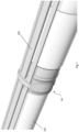
- Figure 1 shows a control line clamp assembly 100 attached to a tubing 200.
- the control line clamp assembly 100 is shown retaining several control lines 300 alongside the tubing 200.
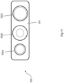
- These control lines 300 may be single control lines, or they may be multiple control lines contained together within a housing or flatpack, such as the flatpack shown in Figure 11 which has a casing 301 surrounding three cables 302a, 302b and 302c.
- the control line clamp assembly 100 has three separate parts, namely a male collar 110, a female collar 120, and a clamping element 130.
- the clamping element 130 is positioned over the control lines 300 and is held in place between the male collar 110 and female collar 120, which together form an attachment mechanism for fixing the control line clamp assembly 100 to the outer surface of the tubing 200.
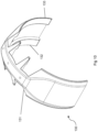
- the male collar 110 is generally tubular in shape and has a plurality of gripping fingers 114 protruding axially at one end, and a groove or recess 111 for retaining part of the clamping element 130 at the opposing end. Additional views of the male collar 110 are shown in Figures 6a, 6b and 6c .
- the gripping fingers 114 of the male collar 110 are created by providing a plurality of equal length, linear and axially aligned slots. A gripping finger 114 is formed between any two adjacent slots. Each of the gripping fingers 114 extends axially away from a tubular body of the male collar 110.
- the gripping fingers 114 may also be referred to as arms, deformable members or other interchangeable terminology to describe a plurality of elements which extend from a base toward a tip and bend or deflect radially inward from a base to grip the pipe, the elements being separated by slots extending from the tip to the base.
- the plurality of gripping fingers 114 is arranged to deflect or bend radially inward by abutment against the inner surface of the female collar 120, as will be described in more detail below.
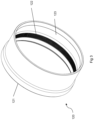
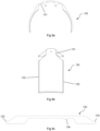
- the female collar 120 is also generally tubular in shape and has a recess 121 for retaining part of the clamping element 130 at one end. Additional views of the female collar 120 are shown in Figures 7a, 7b and 7c .
- the inner surface of the female collar 120 has a tapered portion 123 that gives the inner surface a conical shape, i.e. a section of the wall of the female collar 120 is tapered along its longitudinal axis and is therefore shaped like part of the surface of the cone. This tapering means that one end of the female collar 120 is narrower than the other.
- the outer surfaces of the gripping fingers 114 of the male collar 110 abut against this tapered portion 123.
- the gripping fingers 114 also have tapered portions 116, with a narrower outer diameter at the tip of each finger, that is, at the distal end of each finger. In this way, the tapered gripping fingers 114 may more effectively abut the tapered portion 123 of the female sleeve 120.
- the tapering angle of the tapered portions 116 and 123 is preferably substantially the same.
- the male collar 110 and the female collar 120 are positioned axially on the tubing 200 and the male collar 110 is press fitted into the female collar 120.
- the male collar 110 and the female collar 120 are positioned on or around the tubing 200 such that the end of the female collar 120 with the larger inner diameter is forced over the gripping fingers 114 of the male collar 110.
- the tapered portion 123 of female collar 120 causes the gripping fingers 114 to deflect radially inwards to grip the tubing 200.
- the magnitude of deflection increases as the female collar 120 is pressed further over the gripping fingers 114, which reduces the inner circumference defined by the gripping fingers 114. In this way, the gripping fingers 114 provide an inward force against the tubing 200 to fix the control line clamp assembly 110 to the tubing 200.
- one or more ridged grooves/raised ridges/pawls/circumferential annular catches 115 may be provided on the outer surface of the gripping fingers 114.
- a plurality of ridged grooves/raised ridges/pawls/circumferential annular catches 122 is also provided on an inner surface of the female collar 120.
- the ridges 115 on the gripping fingers 114 and the ridges 122 on the female collar 120 together form a ratchet so that after the female collar 120 has been pressed onto a position where the control line clamp assembly 100 is sufficiently gripped to a pipe, the ratchet holds the male collar 110 and female collar 120 in position relative to each other.
- the illustrated male collar 110 has the ridges 115 on the gripping fingers 114, alternatives are envisaged in which the ridges 115 are instead on the body of the male collar 110, i.e. not on the gripping fingers 114.
- the ridges 115 and 122 are each provided with a conical first face, for example with a pitch in the range of 20-35°, and an opposite second face that forms an abutment surface perpendicular to a central axis of the male collar 110 or female collar 120.
- the ridges 115 and 122 are complementary to each other such that as the female collar 120 is pressed axially onto the gripping fingers 114, each ridge 122 on the female collar 120 slides with a conical inward face against the conical outward faces of the circumferential ridges 115 of the gripping fingers 114.
- the gripping fingers 114 are displaced radially inwards until the ridges 122 of female collar 120 engage behind the ridges 115 of the gripping fingers 114.
- ridges 114 and 122 are typically similarly shaped and arranged with regular axial spacing and corresponding pitch angles.
- a similar attachment mechanism is disclosed in WO 2014/011056 A1 , which is hereby incorporated by reference.
- the inner surface of the gripping fingers 114 may comprise a plurality of gripping teeth 117 which grip the tubing 200 when the gripping fingers 114 are deflected radially inwards as the male collar 110 and female collar 120 are pressed together.
- the illustrated gripping teeth 117 are formed of a plurality of circumferential protrusions on the inner part of the gripping fingers 114 at the proximal end or tip of the fingers. Gripping teeth 117 arranged in this way may prevent axial movement of the control line clamp assembly 100 relative to the tubing 200 by creating an edge which transmits force to the tubing 200.
- the gripping teeth 117 may further comprise a series of longitudinal slits (not shown) in the gripping teeth 117 of each gripping finger 114. Such longitudinal slits help to prevent radial movement of the control line clamp assembly 100 by creating additional edges that can exert a radial force on the tubing 200.
- the outer surface of the male collar 110 has several circumferential teeth 112, which in the illustrated embodiment are formed by ridges spanning the entire circumference of the external surface of the male collar 112 without interruption.
- the circumferential teeth 112 are formed by a series of circumferential ridges (for example, with interruptions or slits between sections of teeth) and/or in which the circumferential teeth 112 only span part of the circumference of the male collar 110.
- the circumferential teeth 112 could be replaced by a rough/textured surface that creates a high friction gripping face for abutting against the control lines 300, for example by providing a rough dotted surface.
- the primary purpose of the circumferential teeth 112 is to slightly embed in the outer surface of the control lines 300 or control line housings/casings in order to prevent axial movement of the control lines 300 relative to the control line clamp assembly 100 and tubing 200.
- the teeth additionally help to restrict circumferential movement of the control lines 300 relative to the control line clamp assembly 100 and tubing 200 by providing an edge for exerting an opposing force on the outer surface of the control lines 300.
- the male collar 110 also has a series of axial protrusions 113 around its outer circumference, which are shaped to interface with a series of axial protrusions or recesses 134 on the inner surface of the clamping element 130, as visible in Figure 4 .
- the axial protrusions 113 on the male collar 110 are most clearly visible in Figure 6b . Channels/recesses/grooves are formed between adjacent axial protrusions 113 and 134.
- the axial protrusions 113 and 134 are optional components that help to reduce rotational movement of the clamping element 130 relative to the male collar 110 and tubing 200 by increasing the strength of the interaction between the clamping element 130 and the male collar 110.
- the axial protrusions interlock and thereby restrict relative rotational movement between these components (as described in further detail below, the clamping element 130 is held in position radially and axially by the male collar 110 and female collar 120).
- the axial protrusions 113 of the male collar taper in an axial direction away from the gripping fingers 114, i.e. the channel formed between adjacent axial protrusions narrows to a point.
- This optional tapering assists in ensuring that the axial protrusions 113 and 134 align correctly when the clamping element 130 is placed onto the male collar 110.
- the axial protrusions 134 on the inner surface of the clamping element may optionally also be tapered.
- the clamping element 130 may either be free to move rotationally relative to the male collar 110 and tubing 200, or may be held in position relative to the male collar 110 and tubing 200 by friction alone (for example through the friction between the inner surface of the clamping element 130 and the outer surface of the male collar 110, or between any other suitable abutting surfaces).
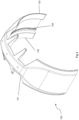
- the clamping element 130 has a cross section similar to the arc of a circle.
- the cross section of the clamping element 130 is similar in shape to a broken circle, such that the clamping element is generally shaped as part of a tube. Additional views of the clamping element are shown in Figures 8a, 8b and 8c .
- the clamping element 130 is preferably manufactured through a casting process, and may be manufactured of any suitable material, such as steel. The clamping element 130 may alternatively be machined.
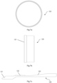
- the arc-shaped cross section of the clamping element 130 may be larger than a semicircle, but alternative embodiments are also envisaged in which the arc-shaped cross section of the clamping element 130 is smaller than a semicircle, such as that shown in Figure 12 .
- Having a cross section larger than a semicircle means that clamping element 130 can be placed against the outer surface of the male collar 110 prior to pressing the male collar 110 and female collar 120 together without the clamping element 130 falling away from the male collar 110.
- this also requires that the clamping element 130 is elastically deformed over the tubing 200 and/or male collar 110 during installation to enable it to fit over the tubing 200 and/or male collar 110.
- the arcuate shape of the clamping element 130 means that it can be placed over the male collar 130 and tubing 200 at any circumferential angle. That is, the clamping element 130 can be positioned anywhere around the circumference of the male collar 110 during installation (as long as the clamping element 130 is aligned with male collar 110 in the axial direction) and does not have to be installed from a particular direction.
- the clamping element 130, male collar 120 and female collar 110 can all be installed at any relative rotational position with respect to each other. This flexibility makes it easier for automated installation of the control line clamp assembly as it removes the need for a specific rotational alignment between the components.
- the clamping element 130 has a first lip or protrusion 132 shaped to be retained in the groove or recess 111 of the male collar 110 and a second lip or protrusion 133 shaped to be retained in the recess 121 of the female collar 120. These lips or protrusions enable the clamping element 130 to be secured in position relative to the tubing 200 by the male collar 110 and female collar 130.
- the lips 132 and 133 are formed as axial flanges protruding from each side of the clamping element 130. While the illustrated lips 132 and 133 are continuous apart from the channels or slots 131 (described below), alternative embodiments are envisaged with discontinuous lips 132 and 133 on one or both sides of the clamping element 130, i.e. multiple shorter lip segments.
- the lips 132 and 133 are shaped to be received in the groove or recess 111 and the recess 121.
- the clamping element 130 is positioned between the male collar 110 and female collar 120 and the two collars are pressed together, the lips 132 and 133 are forced in to the respective groove or recess such that the lips 132 and 133 are at least partly surrounded by the grooves or recesses on the collars.
- each lip 132 and 133 is similar to the radial dimension of the groove or recess into which it is received in order to provide a tight fit that minimises relative radial movement between the clamping element 130 and the collars.
- the axial dimension of the lips 132 and 133 and grooves or recesses should be large enough to ensure that a sufficient length of the lips 132 and 133 is retained within the grooves or recesses to prevent the clamping element 130 coming detached from the collars under high radial or axial forces (for example due to the lips 132 and 133 breaking or deforming or slipping out of the grooves or recesses).
- lips 132 and 133 that are formed by axially protruding flanges
- alternative embodiments are envisaged in which the lips are replaced with other protrusions such as a series of pegs, dowels, catches, arms or fingers that are received in one or more corresponding grooves, recesses or openings on each collar.
- Having multiple axial protrusions on each side of the clamping element 130 that each engage with a corresponding one recess of a similar size i.e. multiple recesses, one for each protrusion restricts relative rotational movement of the clamping element and the collars.
- the protrusions could instead be provided on one or both of the collars, and one or more openings or recesses could be provided on one or both sides of the clamping element 130 for receiving these protrusions.
- the roles of the collars and clamping element could be reversed when it comes to the engagement between the clamping element 130 and the collars.
- the clamping element 130 also has a series of channels or slots 131 for receiving control lines 300.
- the illustrated clamping element 130 has three channels or slots 131, although alternative embodiments are envisaged with more or fewer channels or slots, for example one, two, four, five or six slots.
- the size of each of the channels or slots 131 can be different, and each channel or slot 131 can be sized according to the control line 300 to be received in that slot 131.
- the clamping element 130 is held between the male collar 110 and female collar 120. In the illustrated embodiment, this is achieved by the engagement between the first lip or protrusion 132 of the clamping element 130 and the groove or recess 111 of the male collar 110, and the engagement between the second lip or protrusion 133 of the clamping element 130 and the recess 121 of the female collar 120.
- This engaged or assembled configuration of the control line clamp assembly is shown in Figure 5 .
- the clamping element 130 is positioned abutting the outer surface of the male collar 110, with one or more control lines 300 retained in each slot 131.
- the tapered axial protrusions 113 and 134 help to guide the clamping element 130 into the correct position relative to the male collar 110, i.e. with the respective axial protrusions interlocking.
- the female collar 120 is pressed over the gripping fingers 114 of the male collar 110 as described above.
- the first lip 132 of the clamping element 130 enters the groove or recess 111 of the male collar 110 and the second lip or protrusion 133 of the clamping element 130 enters the recess 121 of the female collar 120.
- both the groove or recess 111 and the recess 121 have tapered sections such that each of the groove or recess 111 and recess 121 is slightly wider at its opening. These tapered sections assist in ensuring the clamping element 130 is pressed tightly against the outer surface of the male collar 110 as the male collar 110 and female collar 120 are pressed together.
- the groove or recess 111 and the recess 121 are preferably sized and shaped to minimise axial and radial movement of the clamping element 130 relative to the collars.
- the sizing of the channels or slots 131 is preferably designed such that the clamping element 130 presses the control lines 300 against the circumferential teeth 112 of the male collar 110, thereby causing the circumferential teeth to embed in the outer surface of the control lines 300 in order to help prevent axial movement of the control lines 300 relative to the control line clamp assembly 100.
- the clamping element 130 must be pressed against the male collar 110 with sufficient force to achieve this.
- attachment in this way means the control line clamp assembly 100 can be attached to a pipe by only pressing the gripping fingers 114 into the female collar 120.
- the control line clamp assembly 100 of the present invention can be mounted to a tubing 200 in an automated manner. No pins, screws or welding are required to attach the control line clamp assembly 100 to the tubing 200.
- control line clamp As the control line clamp according to the present invention is adapted to be installed by a robotic arm or in an automated manner, fewer workers are needed in the red zone on the drill floor. Removing personnel from the red zone during operations on drill floor greatly reduces the overall risk for accidents, and in worst case, deaths. By adding automation in the form of automated installation, the need for personnel can be vastly reduced.
- the attachment of the gripping fingers 114 to the tubing 200 due to the deflection/bending of the gripping fingers 114 allows a very strong gripping force to be applied to the tubing 200.
- the attachment mechanism delivers extremely high holding forces under all operating conditions on a range of different tubing sizes (due to the deflection of the gripping fingers 114 varying depending on how far the male collar 110 and female collar 120 are pressed together).
- control line clamps take a long time to install.
- the press-fit connection of the present invention is quick and easy and dramatically increases the speed of installation and reduces the overall installation time.
- the present invention provides a control line clamp assembly 100 that is compact and easy to handle and can be partially pre-installed onshore.
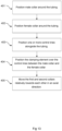
- the male collar 110 and female collar 120 are positioned around the tubing, for example by sliding them over the end of the collar.
- the gripping fingers 114 of the male collar 110 should be facing toward the end of the female collar 120 with the recess 121.
- Steps 401 and 402 may optionally be performed onshore prior to the tubing 200 being deployed, or they may alternatively be performed when the tubing 200 is being deployed. This may either be performed manually by human workers or by a robotic arm, although if these steps being performed when the tubing 200 is being deployed then it is preferred that these steps are performed in an automated manner.
- the male collar 110 and female collar 120 may optionally be pressed together slightly to lightly attach them to the tubing 200, i.e. they may be pressed together such that the gripping fingers are slightly deformed towards the outer surface of the tubing 200 just enough to grip the outer surface of the tubing 200 when no additional load is exerted on the collars.
- the collars should not be pressed fully together, i.e. they should only be pressed such that the clamping element 130 can still be positioned between the recess or groove 111 of the male collar 110 and the recess 121 of the female collar.
- This step is particularly advantageous when the collars are installed onshore, as it will ensure the collars do not move significantly relative to the tubing 200 during transit. Again, this step may either be performed manually by human workers or by robotic or automated installation, but it is preferred that it be performed in an automated manner if this step is being performed during deployment of the tubing 200.
- one or more control lines 300 are positioned alongside the tubing 200, and the clamping element 130 is then positioned over the control lines 300 between the male collar 110 and the female collar in step 404.
- these steps will generally be performed during deployment of the tubing 300, it is preferred for them to be performed by automation, but they may alternatively be performed by human workers.
- the positioning of the control lines 300 alongside the tubing may be performed by a robotic control line manipulator such as that described in US 2013/0186640 A1
- the clamping element 130 may be positioned by a robotic clamp handling device such as that described in US 2008/0023192 A1 .
- step 404 will involve elastically deforming the clamping element 130 in order to allow it to fit over the male collar 110 and tubing 200. This will generally be performed by a specialist tool capable of deforming the clamping element 130 as required.
- the clamping element 130 can be installed from any angle around the circumference of the male collar 110 due to the arcuate shape of the clamping element 130.
- these protrusions and recesses will help to ensure the clamping element 130 is correctly positioned with respect to the male collar 110.
- the clamping element 130 presses the control lines 300 into the circumferential teeth 112, thereby causing the circumferential teeth to bite into the outer surface of each control line 300 in order to restrict axial movement of the control lines 300 relative to the male collar 110.
- the male collar 110 and female collar 120 are moved relatively towards each other in step 405.
- the male collar 110 is held fixed and the female collar 120 pressed over the male collar 110.
- the female collar may 120 may alternatively be held fixed and the male collar 110 pressed into the female, or both collars may be moved simultaneously towards each other.
- any number of known tools for press fitting tubular parts that are arranged around the pipe may be used.
- the press fitting tool as shown in Figures 2 and 3 of US 3,040,405 which is hereby incorporated by reference, may be used.
- Such a press fitting tool may be used in combination with existing robotic clamp handling device such as that described in US 2008/0023192 A1 .
- the arm will position the press fitting tool such that a first pressing surface of the tool abuts the end of the male collar 110 that is furthest from the female collar and a second pressing surface of the tool abuts the end of the female collar 120 that is furthest from the male collar.
- the device will then actuate the tool to apply an axial compression force between the first and second pressing surfaces to thereby press the two collars relatively towards each other and force the male collar 110 and female collar 120 together. This could be performed by moving both pressing surfaces of the tool towards each other, or alternatively by keeping one pressing surface fixed and moving the other. Once the collars are pressed together, the control line clamp assembly 100 will be attached to the tubing.
- control line clamp assembly is suitable for industrial applications, in particular for use in the subsea oil and gas industry.
- the elements of the control line clamp assembly may be made of any material known for such applications, such as steel.
- the dimensions of the components described may be adapted as required to the control lines, pipes and other devices used in these industries.
- control line clamp assembly shows the clamping element 130 abutting the outer surface of the male collar 110, the roles of the male collar 110 and female collar 120 could be swapped such that the clamping element abuts the outer surface of the female collar 120.
- the circumferential teeth 112 may be on the outer surface of the female collar, as may the optional axial protrusions 113.
- alternative embodiments of the assembly may comprise a clamping element with gripping fingers 114, where the assembly is installed by positing the clamping element over the control lines 300 and pressing the gripping fingers 114 of the clamping element into the female collar 120.
- a single collar may be attached to the tubing 200 (for example by welding or using set screws) and the clamping element may be positioned over one or more control lines 300 and attached to the outer surface of the single collar using clips or friction or similar.
- the illustrated embodiment has two lips on the clamping element 130 that are received in corresponding grooves and/or recesses on the male collar 110 and female collar 120
- alternative embodiments are envisaged in which the clamping element 130 has a single lip and only one of the male collar 110 and female collar 120 have a groove or recess.
- the end of the clamping element 130 without a lip will preferably abut against an abutment portion of either the male collar 110 or female collar 120 when the male collar 110 and female collar 120 are pressed together.
- the lip and groove/recess engagement could also be replaced with other engagement interfaces, for example with other forms of interlocking protrusions and openings.
- the male and female collars could be positioned either side of the clamping element and pressed together to engage with the clamping element (for example through the lip and recess arrangement described above), but rather than having deformable fingers that grip the pipe and a ratchet that holds the collars together, the collars could be attached to the pipe by tightening one or more set screws or by welding one or both of them to a pipe. Welding or tightening set screws could either be performed manually or by automation.
Landscapes
- Engineering & Computer Science (AREA)
- Mining & Mineral Resources (AREA)
- Life Sciences & Earth Sciences (AREA)
- Geology (AREA)
- Mechanical Engineering (AREA)
- General Engineering & Computer Science (AREA)
- Geochemistry & Mineralogy (AREA)
- Fluid Mechanics (AREA)
- Environmental & Geological Engineering (AREA)
- General Life Sciences & Earth Sciences (AREA)
- Physics & Mathematics (AREA)
- Clamps And Clips (AREA)
- Light Guides In General And Applications Therefor (AREA)
- Supports For Pipes And Cables (AREA)
- Ropes Or Cables (AREA)
- Vehicle Body Suspensions (AREA)
- Control Of Motors That Do Not Use Commutators (AREA)
Claims (15)
- Steuerleitungsklemme (100), umfassend:ein Klemmelement (130) zum Festhalten einer oder mehrerer Steuerleitungen (300) entlang eines Rohres (200);einen ersten Bund; undeinen zweiten Bund,wobei das Klemmelement (130) angeordnet ist, um durch Positionieren des ersten und zweiten Bundes auf gegenüberliegenden Seiten des Klemmelements (130) um das Rohr (200) herum und Bewegen des ersten und zweiten Bundes in einer axialen Richtung in Bezug zueinander an dem Rohr angebracht zu werden;und wobei:der erste Bund ein Steckbund (110) ist und der zweite Bund eine Rohrmuffe (120) ist, wobei die Rohrmuffe (120) angeordnet ist, um mindestens einen Teil des Steckbundes (110) aufzunehmen; oderder erste Bund eine Rohrmuffe (120) ist und der zweite Bund ein Steckbund (110) ist, wobei die Rohrmuffe (120) angeordnet ist, um mindestens einen Teil des Steckbundes (110) aufzunehmen.
- Steuerleitungsklemme nach Anspruch 1, wobei:der erste Bund einen Eingriffsbereich umfasst, der angeordnet ist, um mit einem ersten Eingriffsbereich am Klemmelement eine Schnittstelle zu bilden; und/oderwobei der zweite Bund einen Eingriffsbereich umfasst, der angeordnet ist, um mit einem zweiten Eingriffsbereich am Klemmelement eine Schnittstelle zu bilden.
- Steuerleitungsklemme nach Anspruch 2, wobei der Eingriffsbereich am ersten und/oder zweiten Bund eine oder mehrere Vertiefungen oder Schlitze (111, 121) umfasst; und wobei der erste und/oder zweite Eingriffsbereich am Klemmelement (130) vorzugsweise eine oder mehrere axiale Lippen oder Vorsprünge (132, 133) umfasst.
- Steuerleitungsklemme nach Anspruch 2, wobei der Eingriffsbereich am ersten und/oder zweiten Bund eine oder mehrere axiale Lippen oder Vorsprünge umfasst und wobei der erste und/oder der zweite Eingriffsbereich am Klemmelement (130) vorzugsweise eine oder mehrere Vertiefungen oder Schlitze umfasst.
- Steuerleitungsklemme nach einem vorstehenden Anspruch, wobei der erste und/oder zweite Bund angepasst sind, um am Rohr (200) und/oder einem anderen Bund befestigt zu werden.
- Steuerleitungsklemme nach einem vorstehenden Anspruch, wobei der Steckbund (110) eine Vielzahl von Fingern (114) umfasst; und:
wobei die Rohrmuffe (120) vorzugsweise angeordnet ist, um die Vielzahl von Fingern (114) aufzunehmen, und wobei, wenn der Steckbund und die Rohrmuffe zusammengepresst werden, jeder der Vielzahl von Fingern (114) nach innen gebogen wird, um das Rohr (200) zu ergreifen. - Steuerleitungsklemme nach einem vorstehenden Anspruch, wobei der Steckbund (110) und die Rohrmuffe (120), wenn sie zusammengepresst werden, durch eine Ratsche zusammengehalten werden.
- Steuerleitungsklemme nach einem vorstehenden Anspruch, wobei eine Innenfläche des Klemmelements (130) angeordnet ist, um an einer umlaufenden Außenfläche des ersten Bundes anzuliegen.
- Steuerleitungsklemme nach Anspruch 8, wobei entweder:die umlaufende Außenfläche des ersten Bundes einen oder mehrere Vorsprünge (113) umfasst, die angeordnet sind, um mit einer oder mehreren entsprechenden Vertiefungen (134) an der Innenfläche des Klemmelements in Eingriff zu gelangen; oderdie umlaufende Außenfläche des ersten Bundes eine oder mehrere Vertiefungen umfasst, die angeordnet sind, um mit einem oder mehreren entsprechenden Vorsprüngen an der Innenfläche des Klemmelements in Eingriff zu gelangen;und wobei vorzugsweise:
der eine oder mehrere Vorsprünge in einer axialen Richtung verjüngt sind, und die eine oder die mehreren entsprechenden Vertiefungen in einer entsprechenden axialen Richtung verjüngt sind. - Steuerleitungsklemme nach einem vorstehenden Anspruch, wobei die umlaufende Außenfläche des ersten Bundes einen oder mehrere umlaufende Zähne (112) umfasst, die angeordnet sind, um mit einer Außenfläche einer Steuerleitung (300) oder eines Steuerleitungsgehäuses in Eingriff zu gelangen.
- Steuerleitungsklemme nach einem vorstehenden Anspruch, wobei die Innenfläche des Klemmelements (130) einen oder mehrere Schlitze (131) umfasst, die angeordnet sind, um eine oder mehrere Steuerleitungen (300) oder Steuerleitungsgehäuse aufzunehmen.
- Steuerleitungsklemme nach einem vorstehenden Anspruch, wobei das Klemmelement (130) einen bogenförmigen Querschnitt aufweist, wobei der bogenförmige Querschnitt vorzugsweise größer als ein Halbkreis, kleiner als ein Halbkreis, oder ein Halbkreis ist.
- Verfahren zum Anbringen einer Steuerleitungsklemme (100) nach einem vorstehenden Anspruch an einem Rohr (200), umfassend:Positionieren des ersten Bundes um das Rohr (200) herum;Positionieren des zweiten Bundes um das Rohr (200) herum;Positionieren einer oder mehrerer Steuerleitungen (300) entlang des Rohres (200);Positionieren des Klemmelements (130) über den Steuerleitungen (300), mit mindestens einem Teil des Klemmelements zwischen mindestens einem Teil des ersten Bundes und mindestens einem Teil des zweiten Bundes; undBewegen des ersten und des zweiten Bundes in Bezug zueinander in einer axialen Richtung, um dadurch das Klemmelement am Rohr (200) anzubringen.
- Verfahren nach Anspruch 13, das weiter das lose Zusammenpressen des ersten und zweiten Bundes vor dem Positionieren eines Klemmelements (130) über den Steuerleitungen (300) zwischen dem ersten und zweiten Bund umfasst, wobei das Bewegen des ersten und des zweiten Bundes in Bezug zueinander in der axialen Richtung ein weiteres Zusammenpressen des ersten und zweiten Bundes umfasst.
- Verfahren nach Anspruch 13 oder Anspruch 14, das vor dem Positionieren der einen oder mehrerer Steuerleitungen (300) entlang des Rohres (200) weiter das leichte Zusammenpressen des ersten Bundes und zweiten Bundes umfasst.
Priority Applications (1)
| Application Number | Priority Date | Filing Date | Title |
|---|---|---|---|
| EP24160827.2A EP4353944A3 (de) | 2020-06-08 | 2021-06-08 | Verfahren mit steuerleitungsklemme |
Applications Claiming Priority (2)
| Application Number | Priority Date | Filing Date | Title |
|---|---|---|---|
| GB2008604.7A GB2595859A (en) | 2020-06-08 | 2020-06-08 | Control line clamp |
| PCT/EP2021/065299 WO2021250005A1 (en) | 2020-06-08 | 2021-06-08 | Control line clamp |
Related Child Applications (2)
| Application Number | Title | Priority Date | Filing Date |
|---|---|---|---|
| EP24160827.2A Division EP4353944A3 (de) | 2020-06-08 | 2021-06-08 | Verfahren mit steuerleitungsklemme |
| EP24160827.2A Division-Into EP4353944A3 (de) | 2020-06-08 | 2021-06-08 | Verfahren mit steuerleitungsklemme |
Publications (4)
| Publication Number | Publication Date |
|---|---|
| EP4162185A1 EP4162185A1 (de) | 2023-04-12 |
| EP4162185B1 true EP4162185B1 (de) | 2024-06-26 |
| EP4162185C0 EP4162185C0 (de) | 2024-06-26 |
| EP4162185B8 EP4162185B8 (de) | 2024-07-31 |
Family
ID=71615893
Family Applications (2)
| Application Number | Title | Priority Date | Filing Date |
|---|---|---|---|
| EP21733729.4A Active EP4162185B8 (de) | 2020-06-08 | 2021-06-08 | Steuerleitungsklemme |
| EP24160827.2A Pending EP4353944A3 (de) | 2020-06-08 | 2021-06-08 | Verfahren mit steuerleitungsklemme |
Family Applications After (1)
| Application Number | Title | Priority Date | Filing Date |
|---|---|---|---|
| EP24160827.2A Pending EP4353944A3 (de) | 2020-06-08 | 2021-06-08 | Verfahren mit steuerleitungsklemme |
Country Status (6)
| Country | Link |
|---|---|
| US (2) | US12188309B2 (de) |
| EP (2) | EP4162185B8 (de) |
| AU (1) | AU2021288919A1 (de) |
| BR (1) | BR112022024965A2 (de) |
| GB (1) | GB2595859A (de) |
| WO (1) | WO2021250005A1 (de) |
Families Citing this family (1)
| Publication number | Priority date | Publication date | Assignee | Title |
|---|---|---|---|---|
| US12252941B2 (en) | 2023-02-10 | 2025-03-18 | Frank's International, Llc | Control line clamp installation system |
Family Cites Families (10)
| Publication number | Priority date | Publication date | Assignee | Title |
|---|---|---|---|---|
| US2040405A (en) | 1935-04-29 | 1936-05-12 | Penn Electric Switch Co | Switch structure with means to prevent arcing upon circuit closure |
| US3040405A (en) | 1958-10-13 | 1962-06-26 | B & W Inc | Compression type stop collar |
| US7249637B2 (en) * | 1997-09-02 | 2007-07-31 | Weatherford/Lamb, Inc. | Method and device to clamp control lines to tubulars |
| GB2398807B (en) * | 2003-02-28 | 2005-07-13 | Schlumberger Holdings | Protecting control lines in a downhole environment |
| US9284792B2 (en) | 2007-04-30 | 2016-03-15 | Frank's International, Llc | Method and apparatus to position and protect control lines being coupled to a pipe string on a rig |
| NO337229B1 (no) | 2012-07-12 | 2016-02-15 | Ace Oil Tools As | Festeanordning for ei rørstamme forsynt med ett eller flere aksielt utragende funksjonselement innrettet til anvendelse på et nedihulls rørlegeme, samt rørstreng omfattende flere rørlegemer |
| NO335999B1 (no) * | 2013-05-08 | 2015-04-20 | Roxar Flow Measurement As | Kabelverninnretning. |
| US20160047174A1 (en) * | 2014-08-13 | 2016-02-18 | Baker Hughes Incorporated | Downhole clamp system |
| GB2540538A (en) * | 2015-07-15 | 2017-01-25 | Ace Oil Tools | Control line clamp system |
| CN106968613A (zh) * | 2017-03-29 | 2017-07-21 | 中国海洋石油总公司 | 一种过滑套外侧的线缆保护工具 |
-
2020
- 2020-06-08 GB GB2008604.7A patent/GB2595859A/en not_active Withdrawn
-
2021
- 2021-06-08 WO PCT/EP2021/065299 patent/WO2021250005A1/en not_active Ceased
- 2021-06-08 US US18/000,850 patent/US12188309B2/en active Active
- 2021-06-08 EP EP21733729.4A patent/EP4162185B8/de active Active
- 2021-06-08 EP EP24160827.2A patent/EP4353944A3/de active Pending
- 2021-06-08 AU AU2021288919A patent/AU2021288919A1/en active Pending
- 2021-06-08 BR BR112022024965A patent/BR112022024965A2/pt unknown
-
2022
- 2022-12-06 US US18/062,175 patent/US11761272B2/en active Active
Also Published As
| Publication number | Publication date |
|---|---|
| EP4353944A3 (de) | 2024-05-29 |
| US20230228158A1 (en) | 2023-07-20 |
| US12188309B2 (en) | 2025-01-07 |
| EP4162185B8 (de) | 2024-07-31 |
| EP4353944A2 (de) | 2024-04-17 |
| BR112022024965A2 (pt) | 2022-12-27 |
| WO2021250005A1 (en) | 2021-12-16 |
| GB2595859A (en) | 2021-12-15 |
| US11761272B2 (en) | 2023-09-19 |
| EP4162185A1 (de) | 2023-04-12 |
| AU2021288919A1 (en) | 2023-01-19 |
| US20230099581A1 (en) | 2023-03-30 |
| GB202008604D0 (en) | 2020-07-22 |
| EP4162185C0 (de) | 2024-06-26 |
Similar Documents
| Publication | Publication Date | Title |
|---|---|---|
| US6120067A (en) | Threaded tool joint for connecting large tubes | |
| US6485061B1 (en) | Threaded tool joint for connecting large diameter tubulars | |
| EP3430299B1 (de) | Push-to-connect-anschlussvorrichtung, -anordnung und -verfahren | |
| EP1598583B1 (de) | Verfahren zur Verwendung einer Anti-Rotations-Einrichtung für komplementäre Verbindungsstücke | |
| US6499772B1 (en) | Radial conduit coupling system and method | |
| US10851600B2 (en) | Stop collar attachment | |
| EA023582B1 (ru) | Трубное соединение | |
| US11761272B2 (en) | Method for attaching a control line clamp | |
| CN114829735B (zh) | 用于管状烃柱中所使用的钢管的装置 | |
| EP0418434A1 (de) | Einstellbare Verbindungsvorrichtung | |
| EP2545243B1 (de) | Kabelkopf | |
| WO2017009440A1 (en) | Control line clamp system | |
| WO2019125176A1 (en) | Pipe quick connector | |
| US11939822B2 (en) | Control line protector assembly | |
| US6241022B1 (en) | Control line connector | |
| US6837646B1 (en) | System for installing underground pipe | |
| GB2591027A (en) | Control line clamp system | |
| EP1025945A1 (de) | Kabelmantelbefestigung insbesondere für einen Schweissbrenner mit einem Kugelgelenk zum Anschluss an dem Stromkabel | |
| CN109996985A (zh) | 密封组件 | |
| GB2572832A (en) | Cable protection system | |
| US5896893A (en) | Pipe having ridge on spigot and method of forming the ridge | |
| CN1527901A (zh) | 盘管连接器 | |
| US20230133454A1 (en) | Clamping device for cable connector assembly | |
| KR102907305B1 (ko) | 방호관 철거용 보조장치 및 방호관 철거 방법 | |
| EP3875822A1 (de) | Koppler zum verbinden mit einem rohr und verfahren zur herstellung des kopplers |
Legal Events
| Date | Code | Title | Description |
|---|---|---|---|
| STAA | Information on the status of an ep patent application or granted ep patent |
Free format text: STATUS: UNKNOWN |
|
| STAA | Information on the status of an ep patent application or granted ep patent |
Free format text: STATUS: THE INTERNATIONAL PUBLICATION HAS BEEN MADE |
|
| PUAI | Public reference made under article 153(3) epc to a published international application that has entered the european phase |
Free format text: ORIGINAL CODE: 0009012 |
|
| STAA | Information on the status of an ep patent application or granted ep patent |
Free format text: STATUS: REQUEST FOR EXAMINATION WAS MADE |
|
| 17P | Request for examination filed |
Effective date: 20221219 |
|
| AK | Designated contracting states |
Kind code of ref document: A1 Designated state(s): AL AT BE BG CH CY CZ DE DK EE ES FI FR GB GR HR HU IE IS IT LI LT LU LV MC MK MT NL NO PL PT RO RS SE SI SK SM TR |
|
| DAV | Request for validation of the european patent (deleted) | ||
| DAX | Request for extension of the european patent (deleted) | ||
| GRAP | Despatch of communication of intention to grant a patent |
Free format text: ORIGINAL CODE: EPIDOSNIGR1 |
|
| STAA | Information on the status of an ep patent application or granted ep patent |
Free format text: STATUS: GRANT OF PATENT IS INTENDED |
|
| INTG | Intention to grant announced |
Effective date: 20240126 |
|
| RAP3 | Party data changed (applicant data changed or rights of an application transferred) |
Owner name: ACE WELL TECHNOLOGY AS |
|
| GRAS | Grant fee paid |
Free format text: ORIGINAL CODE: EPIDOSNIGR3 |
|
| GRAA | (expected) grant |
Free format text: ORIGINAL CODE: 0009210 |
|
| STAA | Information on the status of an ep patent application or granted ep patent |
Free format text: STATUS: THE PATENT HAS BEEN GRANTED |
|
| AK | Designated contracting states |
Kind code of ref document: B1 Designated state(s): AL AT BE BG CH CY CZ DE DK EE ES FI FR GB GR HR HU IE IS IT LI LT LU LV MC MK MT NL NO PL PT RO RS SE SI SK SM TR |
|
| REG | Reference to a national code |
Ref country code: GB Ref legal event code: FG4D |
|
| REG | Reference to a national code |
Ref country code: CH Ref legal event code: EP |
|
| RAP4 | Party data changed (patent owner data changed or rights of a patent transferred) |
Owner name: ACE WELL TECHNOLOGY AS |
|
| REG | Reference to a national code |
Ref country code: CH Ref legal event code: PK Free format text: BERICHTIGUNG B8 |
|
| REG | Reference to a national code |
Ref country code: DE Ref legal event code: R096 Ref document number: 602021014868 Country of ref document: DE |
|
| U01 | Request for unitary effect filed |
Effective date: 20240702 |
|
| U07 | Unitary effect registered |
Designated state(s): AT BE BG DE DK EE FI FR IT LT LU LV MT NL PT SE SI Effective date: 20240710 |
|
| PG25 | Lapsed in a contracting state [announced via postgrant information from national office to epo] |
Ref country code: HR Free format text: LAPSE BECAUSE OF FAILURE TO SUBMIT A TRANSLATION OF THE DESCRIPTION OR TO PAY THE FEE WITHIN THE PRESCRIBED TIME-LIMIT Effective date: 20240626 |
|
| PG25 | Lapsed in a contracting state [announced via postgrant information from national office to epo] |
Ref country code: GR Free format text: LAPSE BECAUSE OF FAILURE TO SUBMIT A TRANSLATION OF THE DESCRIPTION OR TO PAY THE FEE WITHIN THE PRESCRIBED TIME-LIMIT Effective date: 20240927 |
|
| PG25 | Lapsed in a contracting state [announced via postgrant information from national office to epo] |
Ref country code: HR Free format text: LAPSE BECAUSE OF FAILURE TO SUBMIT A TRANSLATION OF THE DESCRIPTION OR TO PAY THE FEE WITHIN THE PRESCRIBED TIME-LIMIT Effective date: 20240626 Ref country code: GR Free format text: LAPSE BECAUSE OF FAILURE TO SUBMIT A TRANSLATION OF THE DESCRIPTION OR TO PAY THE FEE WITHIN THE PRESCRIBED TIME-LIMIT Effective date: 20240927 Ref country code: RS Free format text: LAPSE BECAUSE OF FAILURE TO SUBMIT A TRANSLATION OF THE DESCRIPTION OR TO PAY THE FEE WITHIN THE PRESCRIBED TIME-LIMIT Effective date: 20240926 |
|
| PG25 | Lapsed in a contracting state [announced via postgrant information from national office to epo] |
Ref country code: PL Free format text: LAPSE BECAUSE OF FAILURE TO SUBMIT A TRANSLATION OF THE DESCRIPTION OR TO PAY THE FEE WITHIN THE PRESCRIBED TIME-LIMIT Effective date: 20240626 |
|
| PG25 | Lapsed in a contracting state [announced via postgrant information from national office to epo] |
Ref country code: IS Free format text: LAPSE BECAUSE OF FAILURE TO SUBMIT A TRANSLATION OF THE DESCRIPTION OR TO PAY THE FEE WITHIN THE PRESCRIBED TIME-LIMIT Effective date: 20241026 |
|
| PG25 | Lapsed in a contracting state [announced via postgrant information from national office to epo] |
Ref country code: CZ Free format text: LAPSE BECAUSE OF FAILURE TO SUBMIT A TRANSLATION OF THE DESCRIPTION OR TO PAY THE FEE WITHIN THE PRESCRIBED TIME-LIMIT Effective date: 20240626 |
|
| PG25 | Lapsed in a contracting state [announced via postgrant information from national office to epo] |
Ref country code: RO Free format text: LAPSE BECAUSE OF FAILURE TO SUBMIT A TRANSLATION OF THE DESCRIPTION OR TO PAY THE FEE WITHIN THE PRESCRIBED TIME-LIMIT Effective date: 20240626 Ref country code: SK Free format text: LAPSE BECAUSE OF FAILURE TO SUBMIT A TRANSLATION OF THE DESCRIPTION OR TO PAY THE FEE WITHIN THE PRESCRIBED TIME-LIMIT Effective date: 20240626 |
|
| PG25 | Lapsed in a contracting state [announced via postgrant information from national office to epo] |
Ref country code: ES Free format text: LAPSE BECAUSE OF FAILURE TO SUBMIT A TRANSLATION OF THE DESCRIPTION OR TO PAY THE FEE WITHIN THE PRESCRIBED TIME-LIMIT Effective date: 20240626 Ref country code: SM Free format text: LAPSE BECAUSE OF FAILURE TO SUBMIT A TRANSLATION OF THE DESCRIPTION OR TO PAY THE FEE WITHIN THE PRESCRIBED TIME-LIMIT Effective date: 20240626 |
|
| PG25 | Lapsed in a contracting state [announced via postgrant information from national office to epo] |
Ref country code: SM Free format text: LAPSE BECAUSE OF FAILURE TO SUBMIT A TRANSLATION OF THE DESCRIPTION OR TO PAY THE FEE WITHIN THE PRESCRIBED TIME-LIMIT Effective date: 20240626 Ref country code: SK Free format text: LAPSE BECAUSE OF FAILURE TO SUBMIT A TRANSLATION OF THE DESCRIPTION OR TO PAY THE FEE WITHIN THE PRESCRIBED TIME-LIMIT Effective date: 20240626 Ref country code: RO Free format text: LAPSE BECAUSE OF FAILURE TO SUBMIT A TRANSLATION OF THE DESCRIPTION OR TO PAY THE FEE WITHIN THE PRESCRIBED TIME-LIMIT Effective date: 20240626 Ref country code: PL Free format text: LAPSE BECAUSE OF FAILURE TO SUBMIT A TRANSLATION OF THE DESCRIPTION OR TO PAY THE FEE WITHIN THE PRESCRIBED TIME-LIMIT Effective date: 20240626 Ref country code: IS Free format text: LAPSE BECAUSE OF FAILURE TO SUBMIT A TRANSLATION OF THE DESCRIPTION OR TO PAY THE FEE WITHIN THE PRESCRIBED TIME-LIMIT Effective date: 20241026 Ref country code: ES Free format text: LAPSE BECAUSE OF FAILURE TO SUBMIT A TRANSLATION OF THE DESCRIPTION OR TO PAY THE FEE WITHIN THE PRESCRIBED TIME-LIMIT Effective date: 20240626 Ref country code: CZ Free format text: LAPSE BECAUSE OF FAILURE TO SUBMIT A TRANSLATION OF THE DESCRIPTION OR TO PAY THE FEE WITHIN THE PRESCRIBED TIME-LIMIT Effective date: 20240626 |
|
| PLBE | No opposition filed within time limit |
Free format text: ORIGINAL CODE: 0009261 |
|
| STAA | Information on the status of an ep patent application or granted ep patent |
Free format text: STATUS: NO OPPOSITION FILED WITHIN TIME LIMIT |
|
| 26N | No opposition filed |
Effective date: 20250327 |
|
| U20 | Renewal fee for the european patent with unitary effect paid |
Year of fee payment: 5 Effective date: 20250509 |
|
| PGFP | Annual fee paid to national office [announced via postgrant information from national office to epo] |
Ref country code: GB Payment date: 20250401 Year of fee payment: 5 |
|
| PGFP | Annual fee paid to national office [announced via postgrant information from national office to epo] |
Ref country code: NO Payment date: 20250610 Year of fee payment: 5 |
|
| REG | Reference to a national code |
Ref country code: CH Ref legal event code: H13 Free format text: ST27 STATUS EVENT CODE: U-0-0-H10-H13 (AS PROVIDED BY THE NATIONAL OFFICE) Effective date: 20260127 |
|
| PG25 | Lapsed in a contracting state [announced via postgrant information from national office to epo] |
Ref country code: MC Free format text: LAPSE BECAUSE OF FAILURE TO SUBMIT A TRANSLATION OF THE DESCRIPTION OR TO PAY THE FEE WITHIN THE PRESCRIBED TIME-LIMIT Effective date: 20240626 |