EP4161062A1 - Imaging device and imaging method - Google Patents
Imaging device and imaging method Download PDFInfo
- Publication number
- EP4161062A1 EP4161062A1 EP21814267.7A EP21814267A EP4161062A1 EP 4161062 A1 EP4161062 A1 EP 4161062A1 EP 21814267 A EP21814267 A EP 21814267A EP 4161062 A1 EP4161062 A1 EP 4161062A1
- Authority
- EP
- European Patent Office
- Prior art keywords
- readout
- pixel
- value
- phase difference
- pixels
- Prior art date
- Legal status (The legal status is an assumption and is not a legal conclusion. Google has not performed a legal analysis and makes no representation as to the accuracy of the status listed.)
- Pending
Links
- 238000003384 imaging method Methods 0.000 title claims abstract description 126
- 238000001514 detection method Methods 0.000 claims abstract description 93
- 238000012545 processing Methods 0.000 claims description 78
- 210000001747 pupil Anatomy 0.000 claims description 32
- 238000005516 engineering process Methods 0.000 description 18
- 230000003287 optical effect Effects 0.000 description 16
- 230000006870 function Effects 0.000 description 14
- 238000004364 calculation method Methods 0.000 description 12
- 230000004043 responsiveness Effects 0.000 description 11
- 230000035945 sensitivity Effects 0.000 description 8
- 238000004891 communication Methods 0.000 description 7
- 230000007423 decrease Effects 0.000 description 7
- 230000003595 spectral effect Effects 0.000 description 7
- 238000012937 correction Methods 0.000 description 6
- 230000007246 mechanism Effects 0.000 description 5
- 238000003825 pressing Methods 0.000 description 5
- 230000004044 response Effects 0.000 description 5
- 230000000052 comparative effect Effects 0.000 description 4
- 230000001276 controlling effect Effects 0.000 description 4
- 230000000694 effects Effects 0.000 description 4
- 238000006243 chemical reaction Methods 0.000 description 3
- 238000010586 diagram Methods 0.000 description 3
- 238000005401 electroluminescence Methods 0.000 description 3
- 210000003128 head Anatomy 0.000 description 3
- 230000000737 periodic effect Effects 0.000 description 3
- 230000005540 biological transmission Effects 0.000 description 2
- 230000008859 change Effects 0.000 description 2
- 230000000875 corresponding effect Effects 0.000 description 2
- 230000003111 delayed effect Effects 0.000 description 2
- 238000013461 design Methods 0.000 description 2
- 238000009792 diffusion process Methods 0.000 description 2
- 238000007667 floating Methods 0.000 description 2
- 238000004519 manufacturing process Methods 0.000 description 2
- 238000012986 modification Methods 0.000 description 2
- 230000004048 modification Effects 0.000 description 2
- 238000001454 recorded image Methods 0.000 description 2
- 239000004065 semiconductor Substances 0.000 description 2
- 238000003860 storage Methods 0.000 description 2
- 238000012935 Averaging Methods 0.000 description 1
- 238000009825 accumulation Methods 0.000 description 1
- 230000004075 alteration Effects 0.000 description 1
- 238000003705 background correction Methods 0.000 description 1
- 230000000295 complement effect Effects 0.000 description 1
- 239000002131 composite material Substances 0.000 description 1
- 230000002596 correlated effect Effects 0.000 description 1
- 210000003127 knee Anatomy 0.000 description 1
- 239000004973 liquid crystal related substance Substances 0.000 description 1
- 239000011159 matrix material Substances 0.000 description 1
- 239000002184 metal Substances 0.000 description 1
- 229910044991 metal oxide Inorganic materials 0.000 description 1
- 150000004706 metal oxides Chemical class 0.000 description 1
- 238000000034 method Methods 0.000 description 1
- 238000012544 monitoring process Methods 0.000 description 1
- 238000005096 rolling process Methods 0.000 description 1
- 238000005070 sampling Methods 0.000 description 1
- 229920006395 saturated elastomer Polymers 0.000 description 1
Images


Classifications
-
- H—ELECTRICITY
- H04—ELECTRIC COMMUNICATION TECHNIQUE
- H04N—PICTORIAL COMMUNICATION, e.g. TELEVISION
- H04N25/00—Circuitry of solid-state image sensors [SSIS]; Control thereof
- H04N25/70—SSIS architectures; Circuits associated therewith
- H04N25/703—SSIS architectures incorporating pixels for producing signals other than image signals
- H04N25/704—Pixels specially adapted for focusing, e.g. phase difference pixel sets
-
- H—ELECTRICITY
- H04—ELECTRIC COMMUNICATION TECHNIQUE
- H04N—PICTORIAL COMMUNICATION, e.g. TELEVISION
- H04N23/00—Cameras or camera modules comprising electronic image sensors; Control thereof
- H04N23/60—Control of cameras or camera modules
- H04N23/67—Focus control based on electronic image sensor signals
- H04N23/672—Focus control based on electronic image sensor signals based on the phase difference signals
-
- G—PHYSICS
- G02—OPTICS
- G02B—OPTICAL ELEMENTS, SYSTEMS OR APPARATUS
- G02B7/00—Mountings, adjusting means, or light-tight connections, for optical elements
- G02B7/28—Systems for automatic generation of focusing signals
- G02B7/34—Systems for automatic generation of focusing signals using different areas in a pupil plane
-
- G—PHYSICS
- G03—PHOTOGRAPHY; CINEMATOGRAPHY; ANALOGOUS TECHNIQUES USING WAVES OTHER THAN OPTICAL WAVES; ELECTROGRAPHY; HOLOGRAPHY
- G03B—APPARATUS OR ARRANGEMENTS FOR TAKING PHOTOGRAPHS OR FOR PROJECTING OR VIEWING THEM; APPARATUS OR ARRANGEMENTS EMPLOYING ANALOGOUS TECHNIQUES USING WAVES OTHER THAN OPTICAL WAVES; ACCESSORIES THEREFOR
- G03B13/00—Viewfinders; Focusing aids for cameras; Means for focusing for cameras; Autofocus systems for cameras
- G03B13/32—Means for focusing
- G03B13/34—Power focusing
- G03B13/36—Autofocus systems
-
- H—ELECTRICITY
- H04—ELECTRIC COMMUNICATION TECHNIQUE
- H04N—PICTORIAL COMMUNICATION, e.g. TELEVISION
- H04N23/00—Cameras or camera modules comprising electronic image sensors; Control thereof
- H04N23/10—Cameras or camera modules comprising electronic image sensors; Control thereof for generating image signals from different wavelengths
- H04N23/12—Cameras or camera modules comprising electronic image sensors; Control thereof for generating image signals from different wavelengths with one sensor only
-
- H—ELECTRICITY
- H04—ELECTRIC COMMUNICATION TECHNIQUE
- H04N—PICTORIAL COMMUNICATION, e.g. TELEVISION
- H04N23/00—Cameras or camera modules comprising electronic image sensors; Control thereof
- H04N23/60—Control of cameras or camera modules
-
- H—ELECTRICITY
- H04—ELECTRIC COMMUNICATION TECHNIQUE
- H04N—PICTORIAL COMMUNICATION, e.g. TELEVISION
- H04N23/00—Cameras or camera modules comprising electronic image sensors; Control thereof
- H04N23/70—Circuitry for compensating brightness variation in the scene
- H04N23/73—Circuitry for compensating brightness variation in the scene by influencing the exposure time
-
- H—ELECTRICITY
- H04—ELECTRIC COMMUNICATION TECHNIQUE
- H04N—PICTORIAL COMMUNICATION, e.g. TELEVISION
- H04N25/00—Circuitry of solid-state image sensors [SSIS]; Control thereof
- H04N25/40—Extracting pixel data from image sensors by controlling scanning circuits, e.g. by modifying the number of pixels sampled or to be sampled
- H04N25/44—Extracting pixel data from image sensors by controlling scanning circuits, e.g. by modifying the number of pixels sampled or to be sampled by partially reading an SSIS array
- H04N25/441—Extracting pixel data from image sensors by controlling scanning circuits, e.g. by modifying the number of pixels sampled or to be sampled by partially reading an SSIS array by reading contiguous pixels from selected rows or columns of the array, e.g. interlaced scanning
-
- H—ELECTRICITY
- H04—ELECTRIC COMMUNICATION TECHNIQUE
- H04N—PICTORIAL COMMUNICATION, e.g. TELEVISION
- H04N25/00—Circuitry of solid-state image sensors [SSIS]; Control thereof
- H04N25/40—Extracting pixel data from image sensors by controlling scanning circuits, e.g. by modifying the number of pixels sampled or to be sampled
- H04N25/44—Extracting pixel data from image sensors by controlling scanning circuits, e.g. by modifying the number of pixels sampled or to be sampled by partially reading an SSIS array
- H04N25/445—Extracting pixel data from image sensors by controlling scanning circuits, e.g. by modifying the number of pixels sampled or to be sampled by partially reading an SSIS array by skipping some contiguous pixels within the read portion of the array
-
- H—ELECTRICITY
- H04—ELECTRIC COMMUNICATION TECHNIQUE
- H04N—PICTORIAL COMMUNICATION, e.g. TELEVISION
- H04N25/00—Circuitry of solid-state image sensors [SSIS]; Control thereof
- H04N25/40—Extracting pixel data from image sensors by controlling scanning circuits, e.g. by modifying the number of pixels sampled or to be sampled
- H04N25/46—Extracting pixel data from image sensors by controlling scanning circuits, e.g. by modifying the number of pixels sampled or to be sampled by combining or binning pixels
-
- H—ELECTRICITY
- H04—ELECTRIC COMMUNICATION TECHNIQUE
- H04N—PICTORIAL COMMUNICATION, e.g. TELEVISION
- H04N25/00—Circuitry of solid-state image sensors [SSIS]; Control thereof
- H04N25/50—Control of the SSIS exposure
- H04N25/57—Control of the dynamic range
- H04N25/58—Control of the dynamic range involving two or more exposures
-
- H—ELECTRICITY
- H04—ELECTRIC COMMUNICATION TECHNIQUE
- H04N—PICTORIAL COMMUNICATION, e.g. TELEVISION
- H04N25/00—Circuitry of solid-state image sensors [SSIS]; Control thereof
- H04N25/70—SSIS architectures; Circuits associated therewith
- H04N25/76—Addressed sensors, e.g. MOS or CMOS sensors
- H04N25/7795—Circuitry for generating timing or clock signals
-
- H—ELECTRICITY
- H04—ELECTRIC COMMUNICATION TECHNIQUE
- H04N—PICTORIAL COMMUNICATION, e.g. TELEVISION
- H04N25/00—Circuitry of solid-state image sensors [SSIS]; Control thereof
- H04N25/70—SSIS architectures; Circuits associated therewith
- H04N25/76—Addressed sensors, e.g. MOS or CMOS sensors
- H04N25/78—Readout circuits for addressed sensors, e.g. output amplifiers or A/D converters
Definitions
- the present technology relates to an imaging apparatus and an imaging method that include an imaging element including a pixel group that outputs a phase difference signal.
- Some imaging apparatuses have a function of acquiring focus information concerning a subject in order to perform autofocus control.
- an imaging apparatus for example, an imaging apparatus including pixels for detecting a focal point is known.
- Patent Document 1 discloses a technique of reading out a plurality of image signals that is pupil-divided by an imaging element to perform focal point detection, and controlling a readout row that acquires a plurality of image signals to change the readout row of focal point detection pixels according to an accumulation time or a sensitivity setting of the imaging element.
- Patent Document 1 Japanese Patent Application Laid-Open No. 2018-81224
- a plurality of image signals (pixel values) that is pupil-divided can be read out by pixels according to a photodiode (PD) division system, and in order to read out the image signals, it is known to perform readout of one pixel divided with respect to some of PD divided pixels while reading out addition values of two pixels of PD divided pixels that are divided as normal pixel readout for generating image signals.
- the addition value and one pixel the other pixel value can also be calculated, and phase difference detection can be performed with pixel values of one pixel and the other pixel.
- a readout operation of the imaging element including PD divided pixels is devised so as not to lower the responsiveness of the AF operation.
- An imaging apparatus includes: an imaging element including photodiode divided pixels; and a control unit that performs control to perform, with respect to first readout in which an addition value of a first pixel and a second pixel constituting the photodiode divided pixel is read out as a pixel value constituting an image and second readout of performing readout in which a value of the first pixel and a value of the second pixel used for phase difference detection can be obtained from the photodiode divided pixel that is not a readout target in the first readout, the first readout after performing the second readout in one vertical period.
- the photodiode divided pixel becomes a pixel used for image generation by reading out the addition value of the first pixel and the second pixel.
- PD divided pixel For phase difference detection, readout for obtaining each value of the first pixel and the second pixel is performed. In this case, the second readout for the phase difference detection is performed prior to the first readout in which the addition value is read out.
- the vertical period is a period defined by a vertical synchronization signal, and one frame period of an image.
- control unit performs the second readout and the first readout as readout in the one vertical period in a case where an environment is determined as a bright environment by bright/dark determination.
- the frame rate increases at the time of imaging in a bright environment, and the frame rate decreases at the time of imaging in a dark environment.
- the second readout is performed prior to the first readout in a state where the frame rate is high.
- the control unit performs control to perform third readout in which, with respect to a pixel that is an image generation target, the pixel value constituting the image and the value of the first pixel and the value of the second pixel used for the phase difference detection can be obtained by reading out the addition value of the first pixel and the second pixel and reading out one value out of the first pixel and the second pixel, as readout in the one vertical period.
- a readout operation in which both the pixel value and the values for the phase difference detection are read out is performed as third readout.
- the one value out of the first pixel and the second pixel and the addition value are read out by adding values of a plurality of photodiode divided pixels in a vertical direction.
- the readout of the pixel value is read out as a value obtained by vertical addition in response to a decrease in the value of the pixel due to a decrease in the exposure amount.
- readout is performed for (N-1) horizontal lines in a cycle of N horizontal lines instead of reading out all the horizontal lines. That is, thinning-out readout is performed.
- image generation and phase difference detection are performed from the values of the pixels obtained by thinning-out readout, but the thinning-out rate can be changed according to the lightness condition.
- the value of the other pixel can also be calculated, and each of the value of the first pixel and the value of the second pixel can be obtained.
- the addition value obtained by the first readout is used for generating a live view image.
- the pixel value read out as the addition value of the first pixel and the second pixel is used for a live view image (an image for an imaging monitor, also referred to as a through image) that is an image having a relatively low resolution.
- the imaging element includes light shielding pixels that have a pupil division function by including: a light shielding unit that shields one beam of light of a pair of beams of light that has passed through a pair of partial regions, the partial regions being deviated in directions opposite to each other in a predetermined direction at an exit pupil; and a light receiving element that receives another beam of light, the control unit performs control to perform fourth readout in which the light shielding pixels are read out, and phase difference detection processing is performed by using values of the light shielding pixels obtained in the fourth readout.
- the light shielding pixel is, for example, either one of a pixel on which only light that has passed through the left side region that is a left half region of the exit pupil is incident due to the light shielding unit or a pixel on which only light that has passed through the right side region that is a right half region of the exit pupil is incident due to the light shielding unit.
- the fourth readout is performed prior to the second readout as readout in the one vertical period.
- the readout of the light shielding pixels as the fourth readout and the second readout are performed before and after in a time dividing manner.
- focus control is performed by using a result with higher reliability out of a result of the phase difference detection processing based on the second readout and a result of the phase difference detection processing based on the fourth readout.
- the focus control is performed by selectively using either one of a defocus amount calculated as a phase difference detection result from the light shielding pixels or a defocus amount calculated as a phase difference detection result from the photodiode divided pixels.
- An imaging method includes, as an imaging method of an imaging apparatus that includes an imaging element including photodiode divided pixels, performing control to perform, with respect to first readout in which an addition value of a first pixel and a second pixel constituting the photodiode divided pixel is read out as a pixel value constituting an image and second readout of performing readout in which a value of the first pixel and a value of the second pixel used for phase difference detection can be obtained from the photodiode divided pixel that is not a readout target in the first readout, the first readout after performing the second readout in one vertical period.
- an imaging apparatus is realized in which the first readout and the second readout are performed in a time dividing manner, and the second readout is performed first.
- FIG. 1 , 2 An external appearance of an imaging apparatus 1 according to the present embodiment is illustrated in Figs. 1 , 2 .
- the imaging apparatus 1 includes a camera housing 2 in which necessary units are each arranged inside or outside thereof, and a lens barrel 3 that is attachable to and detachable from the camera housing 2 and is attached to a front surface portion 2a.
- the lens barrel 3 is attachable and detachable as a so-called interchangeable lens by way of example, and may be a lens barrel that cannot be detached from the camera housing 2.
- a rear monitor 4 is arranged on a rear surface portion 2b of the camera housing 2.
- a live view image, a reproduced image of a recorded image, and the like are displayed on the rear monitor 4.
- the rear monitor 4 is, for example, a display device such as a liquid crystal display (LCD) or an organic electro-luminescence (EL) display.
- LCD liquid crystal display
- EL organic electro-luminescence
- the rear monitor 4 is rotatable with respect to the camera housing 2.
- the rear monitor 4 is rotatable such that a lower end portion thereof moves rearward using an upper end portion thereof as a rotation axis.
- a right end portion or a left end portion of the rear monitor 4 may be used as the rotation axis. Moreover, it may be rotatable in a plurality of directions around axes.
- An electric viewfinder (EVF) 5 is arranged on an upper surface portion 2c of the camera housing 2.
- the EVF 5 includes an EVF monitor 5a and a surrounding portion 5b that protrudes rearward in a frame shape so as to surround an upper side and left and right sides of the EVF monitor 5a.
- the EVF monitor 5a is formed using an LCD, an organic EL display, or the like. Note that an optical view finder (OVF) may be provided instead of the EVF monitor 5a.
- OVF optical view finder
- manipulation elements 6 are provided on the rear surface portion 2b and the upper surface portion 2c.
- the manipulation elements 6 are, for example, a reproduction menu start button, a decision button, a cross key, a cancellation button, a zoom key, a slide key, a shutter button 6S (release button), and the like.
- the various manipulation elements 6 include elements in various modes such as a button, a dial, and a composite manipulation element that can be pressed or rotated. With the manipulation elements 6 in various modes, a menu manipulation, a reproduction manipulation, mode selection/switching manipulations, a focus manipulation, a zoom manipulation, selection/setting of parameters such as shutter speed, F value, and the like can be performed, for example.
- Fig. 3 illustrates an internal configuration of such an imaging apparatus 1. Furthermore, Fig. 4 illustrates an arrangement example of a part of the configuration in Fig. 3 .
- An imaging element 7, a camera signal processing unit 8, a recording unit 9, a display unit 10, an output unit 11, a manipulation unit 12, a power supply unit 13, a camera control unit 14, a memory unit 15, and the like are provided inside or outside the camera housing 2 of the imaging apparatus 1.
- the lens barrel 3 includes an optical system 16, a driver unit 17, a barrel control unit 18, a manipulation unit 19, a memory unit 20, and the like.
- the optical system 16 includes various lenses such as an incidence end lens, a zoom lens, a focus lens, and a condenser lens, an aperture mechanism that performs exposure control by adjusting an opening amount by a lens or an iris (aperture) such that sensing is performed in a state where a signal charge falls within a dynamic range without being saturated, and a shutter unit such as a focal plane shutter.
- various lenses such as an incidence end lens, a zoom lens, a focus lens, and a condenser lens, an aperture mechanism that performs exposure control by adjusting an opening amount by a lens or an iris (aperture) such that sensing is performed in a state where a signal charge falls within a dynamic range without being saturated, and a shutter unit such as a focal plane shutter.
- each unit constituting the optical system 16 may be provided in the camera housing 2.
- the imaging element 7 is, for example, of a charge coupled device (CCD) type or a complementary metal-oxide semiconductor (CMOS) type, and performs exposure control of light, from a subject, incident through the optical system 16.
- the imaging element 7 includes a processing unit that performs, for example, correlated double sampling (CDS) processing, automatic gain control (AGC) processing, and analog/digital (A/D) conversion processing with respect to an electric signal that has been photoelectrically converted by a pixel. Therefore, the imaging element 7 outputs imaged image signals as digital data to the camera signal processing unit 8 and the camera control unit 14.
- CDS correlated double sampling
- AGC automatic gain control
- A/D analog/digital
- a sensor surface of the imaging element 7 includes a sensing element in which a plurality of pixels is two-dimensionally arranged.
- the imaging element 7 is formed by arranging PD divided pixels 21 in a matrix in row and column directions.
- Each PD divided pixel 21 includes two divided pixels.
- Fig. 6 schematically illustrates a configuration of the PD divided pixel 21.
- the PD divided pixel 21 includes two divided pixels, that is, a left PD 40L as a divided pixel on a left side and a right PD 40R as a divided pixel on a right side, a pixel boundary metal 41 arranged in front of the left PD 40L and the right PD 40R, an inner lens 32, a color filter 33, an on-chip microlens 34.
- the color filter 33 is any one of a color filter 33R having red (R) spectral sensitivity, a color filter 33G having green (G) spectral sensitivity, and a color filter 33B having blue (B) spectral sensitivity. Note that there is also a configuration example in which the inner lens 32 and the like are not provided.
- the left PD 40L receives light that has passed through a right pupil region EPR of an exit pupil EP.
- the right PD 40R receives light that has passed through a left pupil region EPL. Therefore, a pupil division function is realized.
- Such PD divided pixels 21 are arrayed as R pixels, G pixels, and B pixels as in Fig. 5 due to differences in the color filter 33.
- a signal obtained as an addition value of the left PD 40L and the right PD 40R is a signal of one G pixel. Furthermore, phase difference detection can be performed with values of the left PD 40L and the right PD 40R.
- the camera signal processing unit 8 includes, for example, a microprocessor specialized in digital signal processing such as a digital signal processor (DSP), a microcomputer, or the like.
- DSP digital signal processor
- the camera signal processing unit 8 performs various types of signal processing for digital signals (imaged image signals) transmitted from the imaging element 7.
- processing such as correction processing between color channels of R, G, and B, white balance correction, aberration correction, and shading correction is performed.
- the camera signal processing unit 8 performs YC generation processing in which a brightness (Y) signal and a color (C) signal are generated (separated), processing of adjusting brightness and color, and each of processing such as knee correction and gamma correction, by using the image data of R, G, and B.
- the camera signal processing unit 8 performs conversion into a final output format by performing resolution conversion processing, codec processing of performing encoding for recording or communication, and the like.
- the image data converted into the final output format is stored in the memory unit 15. Furthermore, when the image data is output to the display unit 10, the image is displayed on the rear monitor 4 or the EVF monitor 5a. Moreover, by being output from an external output terminal, it is displayed on a device such as a monitor provided outside the imaging apparatus 1.
- the camera signal processing unit 8 includes a phase difference detection unit 8a.
- the phase difference detection unit 8a performs phase difference detection from output signals of the left PD 40L and the right PD 40R of the PD divided pixel 21. Then, the phase difference detection unit 8a calculates a defocus amount on the basis of the detected phase difference information.
- the calculated defocus amount may be utilized for an autofocus (AF) function by being used for driving the focus lens included in the optical system 16 via the barrel control unit 18. Furthermore, the defocus amount may be used for presentation of information regarding the degree of focus of the subject to a user.
- AF autofocus
- the recording unit 9 includes, for example, a nonvolatile memory, and stores image files (content files) such as still image data or moving image data, attribute information of the image files, thumbnail images, and the like.
- image files content files
- image files such as still image data or moving image data
- attribute information of the image files such as thumbnail images, and the like.
- the image files are stored in a format such as joint photographic experts group (JPEG), tagged image file format (TIFF), and graphics interchange format (GIF), for example.
- JPEG joint photographic experts group
- TIFF tagged image file format
- GIF graphics interchange format
- the recording unit 9 may include a flash memory incorporated in the imaging apparatus 1, or may include a memory card (for example, a portable flash memory) attachable to and detachable from the imaging apparatus 1 and an access unit that performs access for storage and readout to the memory card.
- a flash memory for example, a portable flash memory
- an access unit that performs access for storage and readout to the memory card.
- HDD hard disk drive
- the display unit 10 executes processing for performing various displays for the imaging person.
- the display unit 10 is, for example, the rear monitor 4 or the EVF monitor 5a.
- the display unit 10 performs processing of displaying image data that is input from the camera signal processing unit 8 and is converted into an appropriate resolution. Therefore, a so-called through image that is an image imaged during release standby is displayed.
- the display unit 10 realizes a display as a graphical user interface (GUI) such as various manipulation menus, icons, messages, and the like, on the screen, on the basis of an instruction from the camera control unit 14.
- GUI graphical user interface
- the display unit 10 can display a reproduced image of the image data read out from a recording medium in the recording unit 9.
- both the EVF monitor 5a and the rear monitor 4 are provided, but the implementation of the present technology is not limited to such a configuration, and only either one of the EVF monitor 5a or the rear monitor 4 may be provided, or either one of the EVF monitor 5a or the rear monitor 4 or both of them may be configured to be attachable and detachable.
- the output unit 11 performs data communication or network communication with an external device in a wired or wireless manner. For example, transmission of imaged image data (still image files and moving image files) to a display apparatus, a recording apparatus, a reproduction apparatus, or the like provided outside is performed.
- the output unit 11 may function as a network communication unit.
- communication may be performed through various networks such as the Internet, a home network, or a local area network (LAN) to perform various types of data transmission and reception with a server, a terminal, and the like on the network.
- networks such as the Internet, a home network, or a local area network (LAN) to perform various types of data transmission and reception with a server, a terminal, and the like on the network.
- LAN local area network
- the manipulation unit 12 provided in the camera housing 2 includes not only the above-described various manipulation elements 6, but also the rear monitor 4 employing a touch panel system and the like, and outputs manipulation information according to various manipulations such as a tap manipulation and a swipe manipulation by an imaging person to the camera control unit 14.
- manipulation unit 12 may function as a reception unit of an external manipulation device such as a remote controller separate from the imaging apparatus 1.
- the power supply unit 13 generates a power supply voltage (Vcc) necessary for each unit from, for example, a battery filled inside, and supplies it as an operating voltage.
- Vcc power supply voltage
- the power supply unit 13 is configured to supply the power supply voltage Vcc also to a circuit in the lens barrel 3 in a state where the lens barrel 3 is attached to the imaging apparatus 1.
- a circuit for performing charging to the battery and a circuit for generating the power supply voltage Vcc, using a DC voltage converted and input by an AC adapter connected to a commercial AC power supply as the power supply, may be formed in the power supply unit 13.
- the camera control unit 14 includes a microcomputer (arithmetic processing unit) that includes a central processing unit (CPU), and performs comprehensive control of the imaging apparatus 1. For example, control of a shutter speed according to a manipulation by an imaging person, an instruction of various types of signal processing in the camera signal processing unit 8, an imaging operation and a recording operation according to a user manipulation, and a reproduction operation of recorded image files are performed.
- a microcomputer central processing unit
- the camera control unit 14 performs switching of various image capture modes and the like.
- the various image capture modes are, for example, a still image capture mode, a moving image capture mode, a continuous shooting mode for continuously acquiring still images, and the like.
- the camera control unit 14 includes a user interface control unit (UI control unit) 14a for enabling a user to manipulate these functions.
- the UI control unit 14a performs processing of detecting a manipulation with respect to each manipulation element 6 provided in the imaging apparatus 1, display processing and operation detection processing with respect to the rear monitor 4, and the like.
- the camera control unit 14 performs an instruction with respect to the barrel control unit 18 for controlling various lenses included in the optical system 16.
- processing of designating an aperture value for securing a light amount necessary for AF control, an operation instruction of an aperture mechanism according to an aperture value, and the like are performed.
- the camera control unit 14 can acquire information concerning various lenses included in the optical system 16 via the barrel control unit 18.
- the information about the lens includes, for example, information about model number of the lenses, a position of the zoom lens, F values, information about an exit pupil position, or the like.
- the camera control unit 14 can acquire an aperture value of the aperture mechanism included in the optical system 16.
- the memory unit 15 stores information and the like used for processing executed by the camera control unit 14.
- a read only memory (ROM), a random access memory (RAM), a flash memory, and the like are inclusively illustrated.
- the memory unit 15 may be a memory region incorporated in a microcomputer chip as the camera control unit 14, or may include a separate memory chip.
- Programs and the like utilized by the camera control unit 14 are stored in the ROM, the flash memory, and the like of the memory unit 15.
- OS operating system
- content files such as image files, application programs and firmware for various operations and the like are stored in the ROM, the flash memory, and the like.
- the camera control unit 14 controls the imaging apparatus 1 and the lens barrel 3 as a whole by executing the programs.
- the RAM of the memory unit 15 is utilized as a work region of the camera control unit 14 by temporarily storing data, programs, and the like used at the time of various types of data processing executed by the CPU of the camera control unit 14.
- the barrel control unit 18 of the lens barrel 3 includes, for example, a microcomputer, and outputs a control signal to the driver unit 17 for actually driving various lenses of the optical system 16 on the basis of the instruction from the camera control unit 14.
- information communication between the camera control unit 14 and the barrel control unit 18 may be enabled only in a state where the lens barrel 3 is attached to the camera housing 2, or may be enabled by wireless communication in a state where the lens barrel 3 is not attached to the camera housing 2.
- the barrel control unit 18 transmits information about the position of the exit pupil and the pupil distance of the exit pupil to the camera control unit 14 on the basis of the types and drive positions of various lenses included in the optical system 16. Specifically, information regarding the pupil distance is acquired from information stored in the ROM as the memory unit 20, and is transmitted to the camera control unit 14.
- the driver unit 17 is provided with, for example, a motor driver for a zoom lens drive motor, a motor driver for a focus lens drive motor, an aperture mechanism driver for a motor driving the aperture mechanism, and the like.
- Each driver supplies a drive current to the corresponding driver motor in response to an instruction from the barrel control unit 18.
- the manipulation unit 19 of the lens barrel 3 indicates a manipulation element provided on a lens barrel 3 side.
- the manipulation information by the manipulation unit 19 is supplied to the barrel control unit 18, and is provided in notification to the camera control unit 14 via the barrel control unit 18.
- Operation control of the optical system 16 by the barrel control unit 18, and various settings and operation control by the camera control unit 14 are performed in response to a manipulation of the manipulation unit 19.
- the manipulation unit 19 may function as a reception unit of an external manipulation device such as a remote controller separate from the lens barrel 3.
- the memory unit 20 includes a ROM, a flash memory, and the like, and stores programs, data, and the like utilized by the barrel control unit 18.
- the memory unit 20 stores an operating system (OS) for controlling each unit by the CPU, application programs and firmware for various operations, and the like.
- OS operating system
- information stored in the memory unit 20 includes information about the pupil distance of the exit pupil of the optical system 16 and the like.
- each PD divided pixel 21 including the left PD 40L and the right PD 40R are arrayed as in Fig. 5
- a phase difference signal can be obtained by obtaining values of left and right PDs separately.
- a defocus amount can be calculated from the phase difference signal, and autofocus (AF) control can be executed.
- the "(L + R) readout” refers to readout in which charges from the left PD 40L and the right PD 40R are added.
- the “L readout” refers to charge readout from the left PD 40L
- “R readout” refers to charge readout from the right PD 40R.
- an “L value” is a pixel signal value obtained by direct readout or arithmetic operation from the left PD 40L
- an “R value” is a pixel signal value obtained by direct readout or arithmetic operation from the right PD 40R.
- an (L + R) value is an addition value of the pixel signal values of the left PD 40L and the right PD 40R.
- the (L + R) value that is, an addition value of readout charges from the left PD 40L and the right PD 40R, has a meaning as a pixel value of the PD divided pixel 21, it is a signal used for image generation.
- L readout is performed to obtain a signal value (L value) of the left PD 40L
- a signal value (R value) of the right PD 40R is obtained by the (L + R) value - the L value.
- a phase difference of the pixel components that are pupil-divided can be obtained from the "L value” and the "R value”, and AF control can be performed on the basis of the phase difference.
- Fig. 7 schematically represents such a readout operation.
- Fig. 7 in vertical periods (V1, V2 ...) defined by a vertical synchronization signal XVS, readout timings for respective horizontal lines when assuming the vertical axis as horizontal line numbers are indicated as a straight line SL 10.
- the head horizontal line number is "HL1”
- the last horizontal line number is "HLmax”.
- the " ⁇ " described on the straight line SL 10 indicates a horizontal line for which readout for phase difference detection is also performed.
- a readout operation for each PD divided pixel 21 for each horizontal line is as follows.
- both the L readout and the (L + R) readout are performed for the periodic horizontal lines (in the above example, the forty-eighth horizontal line and the ninety-sixth horizontal line).
- R value is calculated to perform the phase difference detection and calculation of the defocus amount. Since this processing is performed after the necessary L value and (L + R) value are obtained, it is the period illustrated as "phase difference detection" in Fig. 7 . That is, it is after readout of all (or a part of, in a case of performing thinning-out) the horizontal lines for one frame is completed. That is, it becomes possible to execute the phase difference detection for the AF operation after having passed a period indicated by the straight line SL 10 including readout for pixel generation.
- the camera control unit 14 performs lens drive control on the basis of the result of the phase difference detection, and driving of the focus lens is actually performed to focus on the subject.
- Such a delay in the AF operation is undesirable because the user is likely to feel an influence particularly in a case where a moving subject is imaged.
- the frame rate is changed to be high by automatic exposure (AE) control, and when the 1V period becomes shorter, the delay in the AF control described above tends to be noticeable.
- AE automatic exposure
- Fig. 8 schematically illustrates a readout operation as a first embodiment.
- a lateral direction is a time axis, and the vertical periods V1, V2 defined by the vertical synchronization signal XVS are illustrated.
- the vertical periods V1, V2 ..., for example, a case is assumed where the user performs half-pressing the shutter button 6S, and the camera control unit 14 causes the display unit 10 to execute display of the live view image, and performs the AF control.
- An image signal for the live view image for one frame is obtained in one vertical period.
- solid lines RL1, RL2 are illustrated assuming the vertical axis as horizontal line numbers ("HL1" to "HLmax").
- the solid lines RL1, RL2 indicate readout timings for respective horizontal lines.
- readout (second readout) of the solid line RL2 is performed first, and readout (first readout) of the solid line RL1 is subsequently performed.
- the first readout indicated by the solid line RL1 is readout for generating live view images, and the (L + R) readout from each PD divided pixel 21, as a pixel value, is performed.
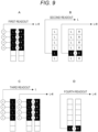
- Fig. 9A schematically illustrates an operation of the first readout.
- the charge readout of the L value + the R value from each horizontal line is performed, and the target horizontal lines are four out of six lines.
- the (L + R) readout is performed for respective PD divided pixels 21 in each of four horizontal lines. Moreover, the (L + R) values read out from the four PD divided pixels 21 in the vertical direction are added (such addition is written as "vertical addition” to distinguish it from addition of the L value + the R value) to obtain one pixel signal.
- the pixel value for generating a live view image is, for example, a vertical addition value of the PD divided pixels 21 in four horizontal lines out of six horizontal lines for every six horizontal lines, and this is obtained as one pixel value for generating a live view image.
- Such readout is performed, for example, from the head horizontal line HL1 side toward the last horizontal line HLmax side in a cycle of six lines.
- the (L + R) value may be read out from one horizontal line for every six horizontal lines to obtain one pixel signal.
- a sufficient level can be easily obtained as a signal level even in a case where the amount of received light is relatively small, which is advantageous.
- Fig. 9A is merely schematically illustrated, and vertical addition is performed for a plurality of pixels connected to the same vertical signal line VSL to be described later with reference to Fig. 13 and provided with color filters of the same color. A similar applies to the vertical addition illustrated in Fig. 9C .
- the second readout indicated as the solid line RL2 in Fig. 8 is readout for phase difference detection, and the L readout and the (L + R) readout from the PD divided pixel 21, as pixel values, are performed.
- the L readout and the (L + R) readout from the PD divided pixel 21 in at least one horizontal line out of the horizontal lines for which the first readout is not performed are performed.
- the L readout and the (L + R) readout are performed for, as a target, the PD divided pixel 21 in one horizontal line for every six horizontal lines.
- the (L + R) value is read out by performing addition of the L value and the R value in a floating diffusion (FD) unit in the imaging element.
- Such readout is performed, for example, from the head horizontal line HL1 side toward the last horizontal line HLmax side in a cycle of six lines.
- Such first readout and second readout are performed in one vertical period, but as illustrated in Fig. 8 , the second readout is performed first, and then the first readout is performed.
- the phase difference detection is performed at a point of time at which the second readout is completed without waiting for the completion of the readout for the image generation, and lens driving can be subsequently executed. Accordingly, the AF operation can be reflected at the timing in the next vertical period V2. Therefore, good AF performance can be realized also with respect to, for example, a moving subject.
- the readout operation as in Fig. 8 may be performed irrespective of bright or dark, but it is also desirably performed when it is determined as a bright environment. This is because AF responsiveness is highly likely to decrease when the frame rate increases in a bright environment and the vertical period becomes shorter, and thus AF operation responsiveness can be improved by performing the second readout and the first readout as in Fig. 8 .
- the readout for image generation and readout for phase difference detection are performed for, as targets, the PD divided pixels 21 in the same horizontal lines. That is, the readout period is not divided as in the above-described first readout and second readout.
- Fig. 9C schematically illustrates an operation of the third readout. Similar to when it is a bright environment, thinning-out readout is performed in a cycle of six horizontal lines in a similar manner.
- Charge readout of the L value + the R value is performed as readout for generating a live view image.
- the target horizontal lines are four out of six lines, and the (L + R) readout is performed for the respective PD divided pixels 21 in each of four horizontal lines, and the (L + R) values read out from the four PD divided pixels 21 in the vertical direction are vertically added to obtain one pixel value.
- the L readout from those four PD divided pixels 21 is performed as readout for the phase difference detection.
- the L values of the four PD divided pixels 21 in the vertical direction are vertically added to obtain one pixel value.
- the R value is obtained by subtracting the L value obtained by vertical addition from the (L + R) value obtained by vertical addition.
- the third readout indicated by the solid line RL3 in Fig. 8 performed as in Fig. 9C is as follows in an example of the cycle of six horizontal lines.
- the phase difference detection is performed after such third readout, and the lens driving can be subsequently executed.
- the phase difference detection is started after the readout of the pixel signals for one frame, but in this case, it is a dark environment, and the frame rate decreases in the dark environment and the vertical period becomes longer. Accordingly, the AF operation can be reflected at the timing in the next vertical period V2. Therefore, for example, good AF performance can be maintained.
- the number of pixels (the number of horizontal lines) for which readout of the (L + R) value and readout of the L value are performed can be reduced as compared with the case where the second readout and the first readout are separately performed as in Fig. 8 .
- readout is performed for a total of five horizontal lines out of six by the second readout and the first readout, but readout is performed for four horizontal lines out of six by the third readout. Therefore, a power-saving effect can be obtained.
- Figs. 8 , 10 are executed on the basis of control by the camera control unit 14.
- Fig. 11 illustrates an example of control processing by the camera control unit 14.
- step S101 in Fig. 11 the camera control unit 14 is monitoring half-pressing of the shutter button 6S. While half-pressing is not being performed, other processing (not illustrated) is performed.
- processing in Fig. 11 proceeds to step S102 and to the subsequent steps every one vertical period.
- the camera control unit 14 When detecting half-pressing of the shutter button 6S, the camera control unit 14 performs exposure arithmetic operation in step S102. This exposure arithmetic operation is performed for determining the shutter speed and an AGC gain for the readout signal, that is, performed for automatic exposure control (AE control).
- AE control automatic exposure control
- Fig. 12 illustrates a processing block for calculating an exposure amount as exposure arithmetic operation.
- a normal pixel output for generating an image signal and a phase difference pixel output as a phase difference signal for AF control are obtained from the imaging element 7.
- the normal pixel output is (L + R) values from the PD divided pixels 21, and the phase difference pixel output is L values and R values.
- the normal pixel output and the phase difference pixel output are each input to an output level detection circuit included in the camera signal processing unit 8.
- the output level detection circuit calculates an output average value in an exposure calculation target region on the pixel on the basis of the input normal pixel output and the input phase difference pixel output, and each output average value is output from the camera signal processing unit 8, and input to the camera control unit 14.
- the camera control unit 14 performs exposure amount calculation according to the detection result output from the camera signal processing unit 8, and determines the shutter speed (or a parameter capable of adjusting the exposure amount such as an F value or a gain). The camera control unit 14 performs processing of setting the determined shutter speed in the imaging element 7.
- the exposure amount calculation performed in the camera control unit 14 may be performed on the basis of only the normal pixel output, or may be performed on the basis of only the phase difference pixel output. Alternatively, the exposure amount calculation may be performed on the basis of both the normal pixel output and the phase difference pixel output. In any case, the bright or dark (illuminance) environment can be determined by the exposure amount calculation.
- the camera control unit 14 performs the readout control in Fig. 8 .
- the second readout is executed in step 5111.
- the readout illustrated in Fig. 9B is performed in a cycle of six horizontal lines, for example.
- step S112 the camera control unit 14 causes the camera signal processing unit 8 to obtain the R value from the L value and the (L + R) value read out for every six horizontal lines and to start the processing of storing the L value and the R value.
- step S113 the camera control unit 14 causes the first readout to be started. That is, the first readout is the readout operation illustrated in Fig. 9A .
- the (L + R) value obtained by vertical addition for 4/6 lines for every six horizontal lines read out in the first readout is processed as an image signal of a live view image in the camera signal processing unit 8.
- the camera control unit 14 causes the first readout to be started, and controls execution of the phase difference detection in step S130 without waiting for the end of the first readout. That is, after the L value and the R value are stored for each PD divided pixel 21, the phase difference detection is performed by a function of the phase difference detection unit 8a in the camera signal processing unit 8. Then, the defocus amount is transmitted to the camera control unit 14.
- step S131 the camera control unit 14 instructs the barrel control unit 18 according to the defocus amount, and causes the barrel control unit 18 to execute driving of the focus lens included in the optical system 16. Then, in step S132, the lens driving is stopped. Therefore, the AF operation is executed.
- step S103 When the EV is less than the threshold thEV in step S103, the camera control unit 14 determines that it is a dark environment, and the processing proceeds to step S121.
- the camera control unit 14 performs control to start readout as the third readout in Fig. 10 .
- the imaging element 7, readout illustrated in Fig. 9C that is, the L readout (vertical addition readout for 4/6 lines) and the (L + R) readout (vertical addition readout for 4/6 lines) for every six horizontal lines are started.
- step S122 the camera control unit 14 causes the camera signal processing unit 8 to obtain the R value from the L value and the (L + R) value read out for every six horizontal lines and to start the processing of storing the L value and the R value.
- Figs. 13A, 13B illustrate modes where signal charges are read out from the PD divided pixels 21 to the vertical signal line VSL.
- the addition as the (L + R) value is an FD addition illustrated in Fig. 13A , and indicates that charges of the left PD 40L and the right PD 40R constituting the PD divided pixel 21 are added by the floating diffusion FD and read out.
- the vertical addition performed for the (L + R) values or the L values is a source follower (SF) addition illustrated in Fig. 13B , and indicates that the signals read out from the PD divided pixels 21 are subjected to the voltage addition in the vertical signal line VSL.
- SF source follower
- the number of horizontal lines in one cycle is N
- the number of N is variable.
- the number of horizontal lines to be subjected to the vertical addition may be variable according to the brightness.
- the imaging element 7 is of a hybrid type including the PD divided pixels 21 and light shielding pixels 23.
- Fig. 14 illustrates a pixel arrangement example of the imaging element 7.
- Pixel rows including the light shielding pixels 23 are formed as first pixel rows 22A.
- the first pixel rows 22A are discretely arranged in the up-and-down direction, and a plurality of rows of second pixel rows 22B is arranged between the first pixel row 22A and the first pixel row 22A.
- the first pixel rows 22A may be regularly arranged, or irregularly arranged. However, regular arrangement can relatively suppress the design cost and the manufacturing cost related to the manufacturing of the imaging element 7.
- the PD divided pixels 21 included in the second pixel rows 22B are each covered with a color filter having a Bayer array, and fall into either one having the red (R) spectral sensitivity, one having the green (G) spectral sensitivity, or one having the blue (B) spectral sensitivity according to the type of the color filter.
- the configuration of the light shielding pixel 23 will be described with reference to the schematic diagram in Fig. 15 .
- the light shielding pixel 23 includes a PD 30, a light shielding unit 31 arranged in front (on the subject side) of the PD 30, an inner lens 32 arranged in front of the light shielding unit 31, a color filter (cyan) 33 arranged in front of the inner lens 32, and an on-chip microlens 34 arranged in front of the color filter 33.
- the light shielding pixel 23 may not be provided with the inner lens 32 and the color filter 33.
- the PD 30 is a light receiving element on which a part of light that has passed through the exit pupil EP is incident, but is capable of receiving light only in a partial region in the light receiving region of the PD 30 due to the light shielding unit 31 arranged in front thereof.
- the light shielding unit 31 is formed so as to cover a left half region of the PD 30.
- a right opening 35R is formed in the light shielding unit 31.
- the inner lens 32 and the on-chip microlens 34 are optical components provided for efficiently condensing light, which has passed through the exit pupil EP and is incident on one pixel, onto the PD 30.
- the color filter 33 is, for example, a filter having cyan (Cy) spectral sensitivity.
- the PD 30 is configured to receive only light that passes through a left side region (left pupil region) that is a left half region of the exit pupil EP. That is, light that passes through a right side region (right pupil region) that is a right half region of the exit pupil EP is shielded by the light shielding unit 31 and does not reach the PD 30. Therefore, a pupil division function is realized.
- the light shielding pixel 23 configured to receive light that passes through the left pupil region as illustrated in Fig. 15 is referred to as a light shielding pixel 23R because it receives light in a region deviated toward the right side on the light receiving surface. That is, the right opening 35R is formed in the light shielding pixel 23R.
- a light shielding pixel 23L that has a mirror symmetrical configuration with respect to the configuration illustrated in Fig. 15 is the light shielding pixel 23 configured to receive light that passes through the right pupil region, and the pixel receives light in a region deviated toward the left side on the light receiving surface.
- a left opening 35L is formed in the light shielding unit 31 included in the light shielding pixel 23L.
- the distance between the light shielding pixel 23R and the light shielding pixel 23L is, for example, a distance corresponding to two pixels, and the light shielding pixel 23R and the light shielding pixel 23L are alternately arranged.
- the signal output from the light shielding pixel 23R and the signal output from the light shielding pixel 23L are treated as a pair of phase difference signals by the camera signal processing unit 8 (or the camera control unit 14). That is, the phase difference detection unit 8a of the camera signal processing unit 8 can perform calculation of the defocus amount using the phase difference between the signal output from the light shielding pixel 23R and the signal output from the light shielding pixel 23L.
- Fig. 16 illustrates a readout operation example in a bright environment in a case where such an imaging element 7 is assumed
- Fig. 17 illustrates a readout operation example in a dark environment.
- fourth readout illustrated as a solid line RL4 is performed first in a vertical period.
- the fourth readout is readout for the phase difference detection, and is to perform (L + R) readout from the light shielding pixels 23 as a pixel value.
- (L + R) readout for the horizontal line is performed in one vertical period.
- the (L + R) readout is performed to enable significant signal readout from both the light shielding pixel 23R and the light shielding pixel 23L.
- the second readout is performed as readout for the phase difference detection in the same manner. Then, after performing the fourth readout and the second readout, the first readout is started and the phase difference detection is started, and then the lens driving is executed.
- the fourth readout illustrated as the solid line RL4 is performed first in a vertical period. Then, thereafter, the third readout is performed. After the third readout, the phase difference detection is started, and then the lens driving is executed.
- the reduced frame rate in the dark environment does not significantly affect AF responsiveness.
- Figs. 16 , 17 are executed on the basis of control by the camera control unit 14.
- Fig. 18 illustrates an example of control processing by the camera control unit 14.
- Steps S101, S102, and S103 in Fig. 18 are similar to those in Fig. 11 , and redundant description is avoided.
- the camera control unit 14 proceeds to step S110, and causes the fourth readout that is targeted at the light shielding pixels 23 to be started.
- the read out (L + R) value of the light shielding pixels 23 is stored in the camera signal processing unit 8.
- the camera control unit 14 causes the second readout, the R value calculation, and storing processing of the L value and the R value to be started as steps S111, S112, and thereafter, causes the first readout to be started in step S113.
- camera control unit 14 causes the first readout to be started, and causes the phase difference detection to be executed in step S130 without waiting for the end of the first readout.
- both the phase difference detection based on the signals of the PD divided pixels 21 and the phase difference detection based on the signals of the light shielding pixels 23 are performed.
- the camera control unit 14 proceeds to step S120, and causes the fourth readout that is targeted at the light shielding pixels 23 to be started.
- the read out (L + R) value of the light shielding pixels 23 is stored in the camera signal processing unit 8.
- the camera control unit 14 causes the third readout, the R value calculation, and the storing processing of the L value and the R value to be started as steps S121, S122.
- step S130 causes the phase difference detection to be executed. Also in this case, both the phase difference detection based on the signals of the PD divided pixels 21 and the phase difference detection based on the signals of the light shielding pixels 23 are performed.
- step S140 the camera control unit 14 determines that which phase difference detection result is highly reliable on the basis of the F value. For example, it is determined whether or not the F value is equal to or larger than a threshold thF.
- a threshold thF F 11 can be conceivable.
- the camera control unit 14 proceeds to step S141, and causes the defocus amount to be obtained by using the phase difference detection result from the PD divided pixel 21, and causes the lens driving to be executed as the AF control. Then, in step S132, the lens driving is stopped, and an in-focus state is obtained.
- the camera control unit 14 proceeds to step S142, causes the defocus amount to be obtained by using the phase difference detection result with higher reliability out of the phase difference detection result from the PD divided pixels 21 and the phase difference detection result from the light shielding pixels 23, and causes the lens driving to be executed as the AF control, and causes an in-focus state to be obtained in step S132.
- the light shielding pixel 23 and the PD divided pixel 21 have the following differences.
- the light shielding pixel 23 is a pixel used only for phase difference detection.
- the PD divided pixel 21 can be used as a normal pixel (pixel for image generation) while being used for phase difference detection. Accordingly, the light shielding pixels 23 are discretely arranged, and the number of pixels cannot be much increased.
- the PD divided pixel 21 is superior to the light shielding pixel 23 in terms of low illuminance performance and large F value performance.
- the light shielding pixel 23 is superior to the PD divided pixel 21 in terms of having pupil correction design flexibility and high off-axis performance.
- the advantages of the PD divided pixel 21 can be utilized under a low illuminance environment, and the advantages of the light shielding pixel 23 can be utilized under a high illuminance environment.
- step S140 the phase difference detection result of the PD divided pixel 21 that is advantageous in terms of the large F value performance is selected.
- step S142 it is conceivable to perform reliability determination on the basis of the illuminance environment. Specifically, one of phase difference signals is selected according to the exposure amount. In a dark environment, the phase difference detection result of the PD divided pixels 21 is selected, and in a bright environment, the phase difference detection result of the light shielding pixels 23 is selected.
- step S130 the phase difference detection result based on the light shielding pixels 23 and the phase difference detection result based on the PD divided pixels 21 are calculated, and then one of the phase difference detection results is selected to be used for the AF control. However, selection may be performed first, and then selected phase difference detection may be executed thereafter.
- the imaging apparatus 1 includes an imaging element 7 including the PD divided pixels 21, and the camera control unit 14.
- the camera control unit 14 performs control to perform, with respect to the first readout in which the addition value (L + R) of the left PD 40L (first pixel) and the right PD 40R (second pixel) constituting the PD divided pixel 21 is read out as a pixel value constituting an image and the second readout of performing readout in which the L value and the R value used for phase difference detection can be obtained from the PD divided pixel 21 that is not a readout target in the first readout, the first readout after performing the second readout in one vertical period.
- Performing the second readout prior to the first readout in one vertical period creates time to spare for the AF control based on the phase difference detection, and makes it possible to control the in-focus state in the next frame. In such a manner, it is possible to improve the responsiveness of the AF control.
- the readout in which the L value and the R value used for phase difference detection can be obtained may be the readout of the (L + R) value and the L value, or may be the readout of the (L + R) value and the R value. Alternatively, it may be readout of the L value and the R value.
- the camera control unit 14 performs the second readout and the first readout as readout in one vertical period in a case where it is determined as a bright environment by the bright/dark determination.
- the length of one vertical period becomes shorter. This tends to cause the AF operation not to be in time for the next frame. In such a case, it is particularly effective not to lower the responsiveness of the AF operation by performing pre-readout as the second readout and performing the phase difference detection at an early stage.
- the camera control unit 14 performs control to perform the third readout in which, with respect to the pixel that is an image generation target, the pixel value constituting the live view image and the L value and the R value used for the phase difference detection can be obtained by reading out the (L + R) value that is an addition value of the left PD 40L and the right PD 40R and reading out the L value of the left PD 40L, as readout in one vertical period.
- the third readout which is simpler than performing the first readout and the second readout separately and in which power consumption can be suppressed, is performed.
- the (L + R) value may be read out, and the R value of the right PD 40R may also be read out.
- the pixel value is obtained by adding and averaging a plurality of PD pixels in the vertical direction and is read out. Therefore, signal level to obtain the phase difference is increased so as not to deteriorate the S/N, and the AF operation is appropriately performed. That is, the low illuminance performance can be improved with respect to the AF operation using the PD divided pixels.
- the number of the total lines to be read out can be reduced, so that the power consumption can be reduced. Note that this operation can shorten the overall readout time, and there may be a case where it also is advantageous for improving the frame rate.
- the L value and the (L + R) value are read out from either one of the remaining two horizontal lines as the second readout. Since this readout is performed for the PD divided pixel 21 in the horizontal line that has not been read out in the first readout, it is sufficient if exposure for the first readout and the second readout is performed in common. That is, it is not necessary to separately set the exposure period for the first readout and the second readout, and an efficient operation can be realized as a readout operation in one vertical period.
- readout is periodically performed in units of six, but periodic readout in units of N is a positional example. It may not be periodic.
- the value of N as a cycle of the horizontal lines may be changed according to the brightness.
- readout is performed twice as readout of the left PD 40L and addition readout of the left PD 40L and the right PD 40R.
- the value of the left PD 40L and the value of the right PD 40R for defocus amount calculation can be obtained.
- each of readout of the left PD 40L and readout of the right PD 40R may be performed.
- the addition value obtained by the first readout is used for generating a live view image.
- the pixel value obtained by the first readout is not obtained as a pixel value of all valid PD divided pixel 21. Therefore, there may be a case where it becomes readout suitable for image generation with relatively low resolution. It is particularly suitable for generating a live view image. Furthermore, as a case where a user views the live view image, it is assumed when the user half-presses the shutter button 6S and is waiting for the release timing while checking the subject. That is, it is an opportunity in which the AF operation is performed. In such a case, it is useful to improve the AF operation responsiveness by performing the second readout prior to the first readout.
- the imaging element 7 includes the light shielding pixels 23 that have a pupil division function by including: the light shielding unit that shields one beam of light of a pair of beams of light that has passed through a pair of partial regions, which are deviated in directions opposite to each other in a predetermined direction at the exit pupil; and the light receiving element that receives the other beam of light.
- the camera control unit 14 performs control to perform the fourth readout in which the light shielding pixels 23 are read out, and the phase difference detection processing is performed by using the values of the light shielding pixels 23 obtained by the fourth readout.
- the imaging element 7 including the PD divided pixels 21 and the light shielding pixels 23 it becomes possible to perform the phase difference detection based on the PD divided pixels 21 and the phase difference detection based on the light shielding pixels 23, which can be selectively used according to a situation, for example.
- the fourth readout is performed prior to the second readout as readout in one vertical period.
- the AF control can be executed on the basis of the fourth readout in a situation in which, for example, reliability of the defocus amount based on the light shielding pixels is high, or the like, and the responsiveness can be improved.
- the focus control is performed by using the result with higher reliability out of the result of the phase difference detection processing based on the second readout and the result of the phase difference detection processing based on the fourth readout (see Fig. 18 ).
- the program according to the embodiment is a program that causes the CPU, the DSP, and the like, or a device including them, for example, to execute processing illustrated in Figs. 11 and 18 .
- the program according to the embodiment is a program that causes the arithmetic processing unit in the imaging apparatus 1 that includes the imaging element 7 including the PD divided pixels 21 to execute, with respect to the first readout in which an addition value of the first pixel and the second pixel constituting the PD divided pixel 21 is read out as a pixel value constituting an image and the second readout of performing readout in which the value of the first pixel and the value of the second pixel used for phase difference detection can be obtained from the PD divided pixel that is not a readout target in the first readout, processing in which the first readout is performed after performing the second readout in one vertical period.
- the above described imaging apparatus 1 can be realized.
- Such a program for realizing the imaging apparatus 1 can be recorded in advance in an HDD as a recording medium incorporated in a device such as the imaging apparatus 1, a ROM in a microcomputer including a CPU, or the like.
- the program can be temporarily or permanently stored (recorded) in a removable recording medium such as a flexible disk, a compact disc read only memory (CD-ROM), a magneto optical (MO) disk, a digital versatile disc (DVD), a Blu-ray Disc (registered trademark), a magnetic disk, a semiconductor memory, or a memory card.
- a removable recording medium such as a flexible disk, a compact disc read only memory (CD-ROM), a magneto optical (MO) disk, a digital versatile disc (DVD), a Blu-ray Disc (registered trademark), a magnetic disk, a semiconductor memory, or a memory card.
- a removable recording medium can be provided as so-called package software.
- Such a program can be installed from a removable recording medium to a personal computer or the like, or can be downloaded from a download site via a network such as a local area network (LAN) or the Internet.
- LAN local area network
- such a program is suitable for providing the imaging apparatus 1 according to the embodiment in a wide range.
- a mobile terminal device such as a smartphone or a tablet having a camera function
- a mobile phone such as a smartphone or a tablet having a camera function
- a mobile phone such as a smartphone or a tablet having a camera function
- a mobile phone such as a smartphone or a tablet having a camera function
- a mobile phone such as a personal computer, a game device, a video device, a personal digital assistant (PDA), or the like
- PDA personal digital assistant
- the present technology can also adopt the following configurations.
Abstract
Description
- The present technology relates to an imaging apparatus and an imaging method that include an imaging element including a pixel group that outputs a phase difference signal.
- Some imaging apparatuses have a function of acquiring focus information concerning a subject in order to perform autofocus control. As such an imaging apparatus, for example, an imaging apparatus including pixels for detecting a focal point is known.
-
Patent Document 1 discloses a technique of reading out a plurality of image signals that is pupil-divided by an imaging element to perform focal point detection, and controlling a readout row that acquires a plurality of image signals to change the readout row of focal point detection pixels according to an accumulation time or a sensitivity setting of the imaging element. - Patent Document 1:
Japanese Patent Application Laid-Open No. 2018-81224 - By the way, a plurality of image signals (pixel values) that is pupil-divided can be read out by pixels according to a photodiode (PD) division system, and in order to read out the image signals, it is known to perform readout of one pixel divided with respect to some of PD divided pixels while reading out addition values of two pixels of PD divided pixels that are divided as normal pixel readout for generating image signals. By reading out the addition value and one pixel, the other pixel value can also be calculated, and phase difference detection can be performed with pixel values of one pixel and the other pixel.
- In a case where such readout is performed during one vertical period (also written as "1V"), and AF control is performed by phase difference detection, there is a case where a response delay by which the AF operation cannot be reflected in a next vertical period occurs.
- Therefore, in the present technology, a readout operation of the imaging element including PD divided pixels is devised so as not to lower the responsiveness of the AF operation.
- An imaging apparatus according to the present technology includes: an imaging element including photodiode divided pixels; and a control unit that performs control to perform, with respect to first readout in which an addition value of a first pixel and a second pixel constituting the photodiode divided pixel is read out as a pixel value constituting an image and second readout of performing readout in which a value of the first pixel and a value of the second pixel used for phase difference detection can be obtained from the photodiode divided pixel that is not a readout target in the first readout, the first readout after performing the second readout in one vertical period.
- The photodiode divided pixel (PD divided pixel) becomes a pixel used for image generation by reading out the addition value of the first pixel and the second pixel. For phase difference detection, readout for obtaining each value of the first pixel and the second pixel is performed. In this case, the second readout for the phase difference detection is performed prior to the first readout in which the addition value is read out.
- Note that the vertical period is a period defined by a vertical synchronization signal, and one frame period of an image.
- In the above-described imaging apparatus according to the present technology, it is conceivable that the control unit performs the second readout and the first readout as readout in the one vertical period in a case where an environment is determined as a bright environment by bright/dark determination.
- Due to automatic exposure control including shutter speed control, the frame rate increases at the time of imaging in a bright environment, and the frame rate decreases at the time of imaging in a dark environment. The second readout is performed prior to the first readout in a state where the frame rate is high.
- In the above-described imaging apparatus according to the present technology, it is conceivable that, in a case where the environment is determined as a dark environment by the bright/dark determination, the control unit performs control to perform third readout in which, with respect to a pixel that is an image generation target, the pixel value constituting the image and the value of the first pixel and the value of the second pixel used for the phase difference detection can be obtained by reading out the addition value of the first pixel and the second pixel and reading out one value out of the first pixel and the second pixel, as readout in the one vertical period.
- At the time of imaging in a dark environment where the frame rate decreases, instead of readout in which the second readout is performed prior to the first readout, a readout operation in which both the pixel value and the values for the phase difference detection are read out is performed as third readout.
- In the above-described imaging apparatus according to the present technology, it is conceivable that, in the third readout, the one value out of the first pixel and the second pixel and the addition value are read out by adding values of a plurality of photodiode divided pixels in a vertical direction.
- In a dark environment, the readout of the pixel value is read out as a value obtained by vertical addition in response to a decrease in the value of the pixel due to a decrease in the exposure amount.
- In the above-described imaging apparatus according to the present technology, it is conceivable that, in the first readout, addition values of the first pixels and the second pixels of the PD divided pixels in (N-1) or less horizontal lines are added in a vertical direction and read out in a cycle of N (N being a natural number of three or more) horizontal lines, and in the second readout, readout is performed in which the value of the first pixel and the value of the second pixel can be obtained from the PD divided pixel in a horizontal line for which readout is not performed in the first readout.
- In the first readout, readout is performed for (N-1) horizontal lines in a cycle of N horizontal lines instead of reading out all the horizontal lines. That is, thinning-out readout is performed.
- In the above-described imaging apparatus according to the present technology, it is conceivable that a value of N as a cycle of the horizontal lines is changed according to brightness.
- In the first readout and the second readout, image generation and phase difference detection are performed from the values of the pixels obtained by thinning-out readout, but the thinning-out rate can be changed according to the lightness condition.
- In the above-described imaging apparatus according to the present technology, it is conceivable that in the second readout, readout of the addition value of the first pixel and the second pixel and readout of one value out of the first pixel and the second pixel are performed.
- By reading out the addition value of the first pixel and the second pixel and the value of one pixel, the value of the other pixel can also be calculated, and each of the value of the first pixel and the value of the second pixel can be obtained.
- In the above-described imaging apparatus according to the present technology, it is conceivable that the addition value obtained by the first readout is used for generating a live view image.
- The pixel value read out as the addition value of the first pixel and the second pixel is used for a live view image (an image for an imaging monitor, also referred to as a through image) that is an image having a relatively low resolution.
- In the above-described imaging apparatus according to the present technology, it is conceivable that the imaging element includes light shielding pixels that have a pupil division function by including: a light shielding unit that shields one beam of light of a pair of beams of light that has passed through a pair of partial regions, the partial regions being deviated in directions opposite to each other in a predetermined direction at an exit pupil; and a light receiving element that receives another beam of light, the control unit performs control to perform fourth readout in which the light shielding pixels are read out, and phase difference detection processing is performed by using values of the light shielding pixels obtained in the fourth readout.
- The light shielding pixel is, for example, either one of a pixel on which only light that has passed through the left side region that is a left half region of the exit pupil is incident due to the light shielding unit or a pixel on which only light that has passed through the right side region that is a right half region of the exit pupil is incident due to the light shielding unit.
- In the above-described imaging apparatus according to the present technology, it is conceivable that the fourth readout is performed prior to the second readout as readout in the one vertical period.
- The readout of the light shielding pixels as the fourth readout and the second readout are performed before and after in a time dividing manner.
- In the above-described imaging apparatus according to the present technology, it is conceivable that focus control is performed by using a result with higher reliability out of a result of the phase difference detection processing based on the second readout and a result of the phase difference detection processing based on the fourth readout.
- The focus control is performed by selectively using either one of a defocus amount calculated as a phase difference detection result from the light shielding pixels or a defocus amount calculated as a phase difference detection result from the photodiode divided pixels.
- An imaging method according to the present technology includes, as an imaging method of an imaging apparatus that includes an imaging element including photodiode divided pixels, performing control to perform, with respect to first readout in which an addition value of a first pixel and a second pixel constituting the photodiode divided pixel is read out as a pixel value constituting an image and second readout of performing readout in which a value of the first pixel and a value of the second pixel used for phase difference detection can be obtained from the photodiode divided pixel that is not a readout target in the first readout, the first readout after performing the second readout in one vertical period.
- Therefore, an imaging apparatus is realized in which the first readout and the second readout are performed in a time dividing manner, and the second readout is performed first.
-
-
Fig. 1 is a perspective view of an imaging apparatus according to an embodiment of the present technology. -
Fig. 2 is a rear view of the imaging apparatus according to the embodiment. -
Fig. 3 is a block diagram of a configuration of the imaging apparatus according to the embodiment. -
Fig. 4 is an explanatory view of a configuration in a lens barrel of the imaging apparatus according to the embodiment. -
Fig. 5 is an explanatory view of an imaging element including PD divided pixels, according to the embodiment. -
Fig. 6 is an explanatory view of a configuration example of a PD divided pixel arranged on an on-axis region. -
Fig. 7 is an explanatory view of a readout operation according to a comparative example. -
Fig. 8 is an explanatory view of a readout operation in a bright environment according to a first embodiment. -
Fig. 9 is a schematic explanatory view of modes of readout according to the embodiment. -
Fig. 10 is an explanatory view of a readout operation in a dark environment according to the first embodiment. -
Fig. 11 is a flowchart of control of readout and an AF operation according to the first embodiment. -
Fig. 12 is a block diagram of a configuration related to calculation of an exposure amount, according to the embodiment. -
Fig. 13 is an explanatory view of FD addition and SF addition according to the embodiment. -
Fig. 14 is an explanatory view of an imaging element including light shielding pixels and PD divided pixels, according to the embodiment. -
Fig. 15 is an explanatory view of a configuration example of a light shielding pixel arranged on an on-axis region. -
Fig. 16 is an explanatory view of a readout operation in a bright environment according to a second embodiment. -
Fig. 17 is an explanatory view of a readout operation in a dark environment according to the second embodiment. -
Fig. 18 is a flowchart of control of readout and an AF operation according to the second embodiment. - Hereinafter, embodiments will be described in the following order with reference to the accompanying drawings.
- <1. Configuration of imaging apparatus>
- <2. Readout operation according to comparative example>
- <3. Readout operation according to first embodiment>
- <4. Readout operation according to second embodiment>
- <5. Summary and modifications>
- An external appearance of an
imaging apparatus 1 according to the present embodiment is illustrated inFigs. 1 ,2 . - Note that, in each of the following examples, description will be made with a subject side as a front and an imaging person side as a rear, but these directions are for convenience of description, and the implementation of the present technology is not limited to these directions.
- As illustrated in
Figs. 1 and2 , theimaging apparatus 1 includes acamera housing 2 in which necessary units are each arranged inside or outside thereof, and alens barrel 3 that is attachable to and detachable from thecamera housing 2 and is attached to afront surface portion 2a. Note that thelens barrel 3 is attachable and detachable as a so-called interchangeable lens by way of example, and may be a lens barrel that cannot be detached from thecamera housing 2. - A
rear monitor 4 is arranged on arear surface portion 2b of thecamera housing 2. A live view image, a reproduced image of a recorded image, and the like are displayed on therear monitor 4. - The
rear monitor 4 is, for example, a display device such as a liquid crystal display (LCD) or an organic electro-luminescence (EL) display. - The
rear monitor 4 is rotatable with respect to thecamera housing 2. For example, therear monitor 4 is rotatable such that a lower end portion thereof moves rearward using an upper end portion thereof as a rotation axis. - Note that a right end portion or a left end portion of the
rear monitor 4 may be used as the rotation axis. Moreover, it may be rotatable in a plurality of directions around axes. - An electric viewfinder (EVF) 5 is arranged on an
upper surface portion 2c of thecamera housing 2. TheEVF 5 includes anEVF monitor 5a and a surroundingportion 5b that protrudes rearward in a frame shape so as to surround an upper side and left and right sides of theEVF monitor 5a. - The
EVF monitor 5a is formed using an LCD, an organic EL display, or the like. Note that an optical view finder (OVF) may be provided instead of theEVF monitor 5a. -
Various manipulation elements 6 are provided on therear surface portion 2b and theupper surface portion 2c. Themanipulation elements 6 are, for example, a reproduction menu start button, a decision button, a cross key, a cancellation button, a zoom key, a slide key, ashutter button 6S (release button), and the like. - The
various manipulation elements 6 include elements in various modes such as a button, a dial, and a composite manipulation element that can be pressed or rotated. With themanipulation elements 6 in various modes, a menu manipulation, a reproduction manipulation, mode selection/switching manipulations, a focus manipulation, a zoom manipulation, selection/setting of parameters such as shutter speed, F value, and the like can be performed, for example. -
Fig. 3 illustrates an internal configuration of such animaging apparatus 1. Furthermore,Fig. 4 illustrates an arrangement example of a part of the configuration inFig. 3 . - An
imaging element 7, a camerasignal processing unit 8, arecording unit 9, adisplay unit 10, an output unit 11, amanipulation unit 12, apower supply unit 13, acamera control unit 14, amemory unit 15, and the like are provided inside or outside thecamera housing 2 of theimaging apparatus 1. - The
lens barrel 3 includes anoptical system 16, adriver unit 17, abarrel control unit 18, amanipulation unit 19, amemory unit 20, and the like. - The
optical system 16 includes various lenses such as an incidence end lens, a zoom lens, a focus lens, and a condenser lens, an aperture mechanism that performs exposure control by adjusting an opening amount by a lens or an iris (aperture) such that sensing is performed in a state where a signal charge falls within a dynamic range without being saturated, and a shutter unit such as a focal plane shutter. - Note that a part of each unit constituting the
optical system 16 may be provided in thecamera housing 2. - The
imaging element 7 is, for example, of a charge coupled device (CCD) type or a complementary metal-oxide semiconductor (CMOS) type, and performs exposure control of light, from a subject, incident through theoptical system 16. In addition, theimaging element 7 includes a processing unit that performs, for example, correlated double sampling (CDS) processing, automatic gain control (AGC) processing, and analog/digital (A/D) conversion processing with respect to an electric signal that has been photoelectrically converted by a pixel. Therefore, theimaging element 7 outputs imaged image signals as digital data to the camerasignal processing unit 8 and thecamera control unit 14. - A sensor surface of the
imaging element 7 includes a sensing element in which a plurality of pixels is two-dimensionally arranged. - As illustrated in
Fig. 5 , theimaging element 7 is formed by arranging PD dividedpixels 21 in a matrix in row and column directions. Each PD dividedpixel 21 includes two divided pixels. -
Fig. 6 schematically illustrates a configuration of the PD dividedpixel 21. - The PD divided
pixel 21 includes two divided pixels, that is, a leftPD 40L as a divided pixel on a left side and aright PD 40R as a divided pixel on a right side, apixel boundary metal 41 arranged in front of theleft PD 40L and theright PD 40R, aninner lens 32, acolor filter 33, an on-chip microlens 34. Thecolor filter 33 is any one of a color filter 33R having red (R) spectral sensitivity, a color filter 33G having green (G) spectral sensitivity, and a color filter 33B having blue (B) spectral sensitivity. Note that there is also a configuration example in which theinner lens 32 and the like are not provided. - As illustrated, the
left PD 40L receives light that has passed through a right pupil region EPR of an exit pupil EP. Theright PD 40R receives light that has passed through a left pupil region EPL. Therefore, a pupil division function is realized. - Such PD divided
pixels 21 are arrayed as R pixels, G pixels, and B pixels as inFig. 5 due to differences in thecolor filter 33. - For example, in a case of a G pixel as one PD divided
pixel 21, a signal obtained as an addition value of theleft PD 40L and theright PD 40R is a signal of one G pixel. Furthermore, phase difference detection can be performed with values of theleft PD 40L and theright PD 40R. - Returning to
Fig. 3 , the description will be given. The camerasignal processing unit 8 includes, for example, a microprocessor specialized in digital signal processing such as a digital signal processor (DSP), a microcomputer, or the like. - The camera
signal processing unit 8 performs various types of signal processing for digital signals (imaged image signals) transmitted from theimaging element 7. - Specifically, processing such as correction processing between color channels of R, G, and B, white balance correction, aberration correction, and shading correction is performed.
- Furthermore, the camera
signal processing unit 8 performs YC generation processing in which a brightness (Y) signal and a color (C) signal are generated (separated), processing of adjusting brightness and color, and each of processing such as knee correction and gamma correction, by using the image data of R, G, and B. - Moreover, the camera
signal processing unit 8 performs conversion into a final output format by performing resolution conversion processing, codec processing of performing encoding for recording or communication, and the like. The image data converted into the final output format is stored in thememory unit 15. Furthermore, when the image data is output to thedisplay unit 10, the image is displayed on therear monitor 4 or theEVF monitor 5a. Moreover, by being output from an external output terminal, it is displayed on a device such as a monitor provided outside theimaging apparatus 1. - The camera
signal processing unit 8 includes a phasedifference detection unit 8a. - The phase
difference detection unit 8a performs phase difference detection from output signals of theleft PD 40L and theright PD 40R of the PD dividedpixel 21. Then, the phasedifference detection unit 8a calculates a defocus amount on the basis of the detected phase difference information. The calculated defocus amount may be utilized for an autofocus (AF) function by being used for driving the focus lens included in theoptical system 16 via thebarrel control unit 18. Furthermore, the defocus amount may be used for presentation of information regarding the degree of focus of the subject to a user. - The
recording unit 9 includes, for example, a nonvolatile memory, and stores image files (content files) such as still image data or moving image data, attribute information of the image files, thumbnail images, and the like. - The image files are stored in a format such as joint photographic experts group (JPEG), tagged image file format (TIFF), and graphics interchange format (GIF), for example.
- Various forms are conceivable as the actual form of the
recording unit 9. For example, therecording unit 9 may include a flash memory incorporated in theimaging apparatus 1, or may include a memory card (for example, a portable flash memory) attachable to and detachable from theimaging apparatus 1 and an access unit that performs access for storage and readout to the memory card. Furthermore, it may be realized in a form of a hard disk drive (HDD) and the like incorporated in theimaging apparatus 1. - The
display unit 10 executes processing for performing various displays for the imaging person. Thedisplay unit 10 is, for example, therear monitor 4 or theEVF monitor 5a. Thedisplay unit 10 performs processing of displaying image data that is input from the camerasignal processing unit 8 and is converted into an appropriate resolution. Therefore, a so-called through image that is an image imaged during release standby is displayed. - Moreover, the
display unit 10 realizes a display as a graphical user interface (GUI) such as various manipulation menus, icons, messages, and the like, on the screen, on the basis of an instruction from thecamera control unit 14. - Furthermore, the
display unit 10 can display a reproduced image of the image data read out from a recording medium in therecording unit 9. - Note that, in the present example, both the
EVF monitor 5a and therear monitor 4 are provided, but the implementation of the present technology is not limited to such a configuration, and only either one of theEVF monitor 5a or therear monitor 4 may be provided, or either one of theEVF monitor 5a or therear monitor 4 or both of them may be configured to be attachable and detachable. - The output unit 11 performs data communication or network communication with an external device in a wired or wireless manner. For example, transmission of imaged image data (still image files and moving image files) to a display apparatus, a recording apparatus, a reproduction apparatus, or the like provided outside is performed.
- Furthermore, the output unit 11 may function as a network communication unit. For example, communication may be performed through various networks such as the Internet, a home network, or a local area network (LAN) to perform various types of data transmission and reception with a server, a terminal, and the like on the network.
- The
manipulation unit 12 provided in thecamera housing 2 includes not only the above-describedvarious manipulation elements 6, but also therear monitor 4 employing a touch panel system and the like, and outputs manipulation information according to various manipulations such as a tap manipulation and a swipe manipulation by an imaging person to thecamera control unit 14. - Note that the
manipulation unit 12 may function as a reception unit of an external manipulation device such as a remote controller separate from theimaging apparatus 1. - The
power supply unit 13 generates a power supply voltage (Vcc) necessary for each unit from, for example, a battery filled inside, and supplies it as an operating voltage. - The
power supply unit 13 is configured to supply the power supply voltage Vcc also to a circuit in thelens barrel 3 in a state where thelens barrel 3 is attached to theimaging apparatus 1. - Note that a circuit for performing charging to the battery and a circuit for generating the power supply voltage Vcc, using a DC voltage converted and input by an AC adapter connected to a commercial AC power supply as the power supply, may be formed in the
power supply unit 13. - The
camera control unit 14 includes a microcomputer (arithmetic processing unit) that includes a central processing unit (CPU), and performs comprehensive control of theimaging apparatus 1. For example, control of a shutter speed according to a manipulation by an imaging person, an instruction of various types of signal processing in the camerasignal processing unit 8, an imaging operation and a recording operation according to a user manipulation, and a reproduction operation of recorded image files are performed. - The
camera control unit 14 performs switching of various image capture modes and the like. The various image capture modes are, for example, a still image capture mode, a moving image capture mode, a continuous shooting mode for continuously acquiring still images, and the like. - The
camera control unit 14 includes a user interface control unit (UI control unit) 14a for enabling a user to manipulate these functions. The UI control unit 14a performs processing of detecting a manipulation with respect to eachmanipulation element 6 provided in theimaging apparatus 1, display processing and operation detection processing with respect to therear monitor 4, and the like. - Furthermore, the
camera control unit 14 performs an instruction with respect to thebarrel control unit 18 for controlling various lenses included in theoptical system 16. - For example, processing of designating an aperture value for securing a light amount necessary for AF control, an operation instruction of an aperture mechanism according to an aperture value, and the like are performed.
- The
camera control unit 14 can acquire information concerning various lenses included in theoptical system 16 via thebarrel control unit 18. The information about the lens includes, for example, information about model number of the lenses, a position of the zoom lens, F values, information about an exit pupil position, or the like. Furthermore, thecamera control unit 14 can acquire an aperture value of the aperture mechanism included in theoptical system 16. - The
memory unit 15 stores information and the like used for processing executed by thecamera control unit 14. As the illustratedmemory unit 15, for example, a read only memory (ROM), a random access memory (RAM), a flash memory, and the like are inclusively illustrated. - The
memory unit 15 may be a memory region incorporated in a microcomputer chip as thecamera control unit 14, or may include a separate memory chip. - Programs and the like utilized by the
camera control unit 14 are stored in the ROM, the flash memory, and the like of thememory unit 15. In addition to an operating system (OS) for controlling each unit by the CPU and content files such as image files, application programs and firmware for various operations and the like are stored in the ROM, the flash memory, and the like. - The
camera control unit 14 controls theimaging apparatus 1 and thelens barrel 3 as a whole by executing the programs. - The RAM of the
memory unit 15 is utilized as a work region of thecamera control unit 14 by temporarily storing data, programs, and the like used at the time of various types of data processing executed by the CPU of thecamera control unit 14. - The
barrel control unit 18 of thelens barrel 3 includes, for example, a microcomputer, and outputs a control signal to thedriver unit 17 for actually driving various lenses of theoptical system 16 on the basis of the instruction from thecamera control unit 14. - Note that information communication between the
camera control unit 14 and thebarrel control unit 18 may be enabled only in a state where thelens barrel 3 is attached to thecamera housing 2, or may be enabled by wireless communication in a state where thelens barrel 3 is not attached to thecamera housing 2. - The
barrel control unit 18 transmits information about the position of the exit pupil and the pupil distance of the exit pupil to thecamera control unit 14 on the basis of the types and drive positions of various lenses included in theoptical system 16. Specifically, information regarding the pupil distance is acquired from information stored in the ROM as thememory unit 20, and is transmitted to thecamera control unit 14. - The
driver unit 17 is provided with, for example, a motor driver for a zoom lens drive motor, a motor driver for a focus lens drive motor, an aperture mechanism driver for a motor driving the aperture mechanism, and the like. - Each driver supplies a drive current to the corresponding driver motor in response to an instruction from the
barrel control unit 18. - The
manipulation unit 19 of thelens barrel 3 indicates a manipulation element provided on alens barrel 3 side. The manipulation information by themanipulation unit 19 is supplied to thebarrel control unit 18, and is provided in notification to thecamera control unit 14 via thebarrel control unit 18. - Operation control of the
optical system 16 by thebarrel control unit 18, and various settings and operation control by thecamera control unit 14 are performed in response to a manipulation of themanipulation unit 19. - The
manipulation unit 19 may function as a reception unit of an external manipulation device such as a remote controller separate from thelens barrel 3. - The
memory unit 20 includes a ROM, a flash memory, and the like, and stores programs, data, and the like utilized by thebarrel control unit 18. Thememory unit 20 stores an operating system (OS) for controlling each unit by the CPU, application programs and firmware for various operations, and the like. - Furthermore, information stored in the
memory unit 20 includes information about the pupil distance of the exit pupil of theoptical system 16 and the like. - Here, as a comparative example, an event will be described in which response of the AF operation is delayed in a case of performing readout of pixel values from the
imaging element 7 including the PD dividedpixels 21. Note that readout refers to a case of performing rolling shutter readout. - In a case of the
imaging element 7 where the PD dividedpixels 21 including the leftPD 40L and theright PD 40R are arrayed as inFig. 5 , in each PD dividedpixel 21, not only a normal pixel signal for image generation can be read out, but also a phase difference signal can be obtained by obtaining values of left and right PDs separately. A defocus amount can be calculated from the phase difference signal, and autofocus (AF) control can be executed. - Accordingly, it is conceivable to perform readout twice for one horizontal line so as to perform, for example, (L + R) readout and L readout for one PD divided
pixel 21. - Note that the "(L + R) readout" refers to readout in which charges from the
left PD 40L and theright PD 40R are added. The "L readout" refers to charge readout from theleft PD 40L, and "R readout" refers to charge readout from theright PD 40R. Furthermore, an "L value" is a pixel signal value obtained by direct readout or arithmetic operation from theleft PD 40L, and an "R value" is a pixel signal value obtained by direct readout or arithmetic operation from theright PD 40R. Furthermore, an (L + R) value is an addition value of the pixel signal values of theleft PD 40L and theright PD 40R. - Since the (L + R) value, that is, an addition value of readout charges from the
left PD 40L and theright PD 40R, has a meaning as a pixel value of the PD dividedpixel 21, it is a signal used for image generation. - Furthermore, L readout is performed to obtain a signal value (L value) of the
left PD 40L, and a signal value (R value) of theright PD 40R is obtained by the (L + R) value - the L value. A phase difference of the pixel components that are pupil-divided can be obtained from the "L value" and the "R value", and AF control can be performed on the basis of the phase difference. -
Fig. 7 schematically represents such a readout operation. - In
Fig. 7 , in vertical periods (V1, V2 ...) defined by a vertical synchronization signal XVS, readout timings for respective horizontal lines when assuming the vertical axis as horizontal line numbers are indicated as astraight line SL 10. The head horizontal line number is "HL1", and the last horizontal line number is "HLmax". The "●" described on thestraight line SL 10 indicates a horizontal line for which readout for phase difference detection is also performed. - For example, assuming that readout for phase difference detection is performed every forty-eight lines, a readout operation for each PD divided
pixel 21 for each horizontal line is as follows. - First horizontal line: (L + R) readout
- Second horizontal line: (L + R) readout
- Third horizontal line: (L + R) readout
(hereinafter, (L + R) readout being similarly performed up to a forty-seventh horizontal line)) - Forty-eighth horizontal line: L readout
- Forty-eighth horizontal line: (L + R) readout
- Forty-ninth horizontal line: (L + R) readout
- Fiftieth horizontal line: (L + R) readout
(hereinafter, (L + R) readout being similarly performed up to a ninety-fifth horizontal line) - Ninety-sixth horizontal line: L readout
- Ninety-sixth horizontal line: (L + R) readout
- Ninety-seventh horizontal line: (L + R) readout
- Ninety-eighth horizontal line: (L + R) readout
- In this manner, both the L readout and the (L + R) readout are performed for the periodic horizontal lines (in the above example, the forty-eighth horizontal line and the ninety-sixth horizontal line).
- This is because when both the L readout and the (L + R) readout are performed for all the horizontal lines, readout time for one frame becomes longer.
- However, performing readout for image generation and readout for phase difference detection in this manner may cause a case where the AF operation is delayed.
- After reading out the L value and the (L + R) value, R value is calculated to perform the phase difference detection and calculation of the defocus amount. Since this processing is performed after the necessary L value and (L + R) value are obtained, it is the period illustrated as "phase difference detection" in
Fig. 7 . That is, it is after readout of all (or a part of, in a case of performing thinning-out) the horizontal lines for one frame is completed. That is, it becomes possible to execute the phase difference detection for the AF operation after having passed a period indicated by thestraight line SL 10 including readout for pixel generation. - The
camera control unit 14 performs lens drive control on the basis of the result of the phase difference detection, and driving of the focus lens is actually performed to focus on the subject. - In such a case, as illustrated in the drawing, there arises a delay in reflection of an in-focus state until not the next frame (the timing in the vertical period V2), but further next frame (the timing in the vertical period V3). This is because the start timing of the phase difference detection is after readout for one frame.
- Such a delay in the AF operation is undesirable because the user is likely to feel an influence particularly in a case where a moving subject is imaged.
- Furthermore, in a light environment (bright environment), the frame rate is changed to be high by automatic exposure (AE) control, and when the 1V period becomes shorter, the delay in the AF control described above tends to be noticeable.
- Therefore, in the embodiment, a readout operation that does not cause such a delay in responsiveness of the AF operation is performed.
-
Fig. 8 schematically illustrates a readout operation as a first embodiment. - In
Fig. 8 , a lateral direction is a time axis, and the vertical periods V1, V2 defined by the vertical synchronization signal XVS are illustrated. As the vertical periods V1, V2 ..., for example, a case is assumed where the user performs half-pressing theshutter button 6S, and thecamera control unit 14 causes thedisplay unit 10 to execute display of the live view image, and performs the AF control. An image signal for the live view image for one frame is obtained in one vertical period. - Furthermore, in the drawing, solid lines RL1, RL2 are illustrated assuming the vertical axis as horizontal line numbers ("HL1" to "HLmax"). The solid lines RL1, RL2 indicate readout timings for respective horizontal lines.
- As illustrated in the drawing, in one vertical period, readout (second readout) of the solid line RL2 is performed first, and readout (first readout) of the solid line RL1 is subsequently performed.
- Although not represented in
Fig. 8 , since the first readout and the second readout are targeted at different horizontal lines as illustrated inFigs. 9A, 9B described later, it is sufficient if exposure is performed before each readout, and it is sufficient if the timing and length of the exposure of each horizontal line are not particularly defined, and is appropriately set. - The first readout indicated by the solid line RL1 is readout for generating live view images, and the (L + R) readout from each PD divided
pixel 21, as a pixel value, is performed. - As an example, description will be made assuming that the (L + R) readout is performed in a cycle of six horizontal lines in one vertical period.
-
Fig. 9A schematically illustrates an operation of the first readout. The charge readout of the L value + the R value from each horizontal line is performed, and the target horizontal lines are four out of six lines. - The (L + R) readout is performed for respective PD divided
pixels 21 in each of four horizontal lines. Moreover, the (L + R) values read out from the four PD dividedpixels 21 in the vertical direction are added (such addition is written as "vertical addition" to distinguish it from addition of the L value + the R value) to obtain one pixel signal. - That is, the pixel value for generating a live view image is, for example, a vertical addition value of the PD divided
pixels 21 in four horizontal lines out of six horizontal lines for every six horizontal lines, and this is obtained as one pixel value for generating a live view image. - Such readout is performed, for example, from the head horizontal line HL1 side toward the last horizontal line HLmax side in a cycle of six lines.
- Note that, for example, as simple thinning-out readout, the (L + R) value may be read out from one horizontal line for every six horizontal lines to obtain one pixel signal. However, by performing vertical addition, a sufficient level can be easily obtained as a signal level even in a case where the amount of received light is relatively small, which is advantageous.
- Note that
Fig. 9A is merely schematically illustrated, and vertical addition is performed for a plurality of pixels connected to the same vertical signal line VSL to be described later with reference toFig. 13 and provided with color filters of the same color. A similar applies to the vertical addition illustrated inFig. 9C . - Furthermore, these are voltage addition in the vertical signal line VSL.
- The second readout indicated as the solid line RL2 in
Fig. 8 is readout for phase difference detection, and the L readout and the (L + R) readout from the PD dividedpixel 21, as pixel values, are performed. - As schematically illustrated in
Fig. 9B , in each cycle of six horizontal lines in one vertical period, the L readout and the (L + R) readout from the PD dividedpixel 21 in at least one horizontal line out of the horizontal lines for which the first readout is not performed are performed. - That is, in the second readout, the L readout and the (L + R) readout are performed for, as a target, the PD divided
pixel 21 in one horizontal line for every six horizontal lines. - In the readout, for example, after the readout of the L value from the
left PD 40L, processing of readout of the image signal of theright PD 40R is performed without resetting the charge. That is, the (L + R) value is read out by performing addition of the L value and the R value in a floating diffusion (FD) unit in the imaging element. - Such readout is performed, for example, from the head horizontal line HL1 side toward the last horizontal line HLmax side in a cycle of six lines.
- Such first readout and second readout are performed in one vertical period, but as illustrated in
Fig. 8 , the second readout is performed first, and then the first readout is performed. - The phase difference detection is performed at a point of time at which the second readout is completed without waiting for the completion of the readout for the image generation, and lens driving can be subsequently executed. Accordingly, the AF operation can be reflected at the timing in the next vertical period V2. Therefore, good AF performance can be realized also with respect to, for example, a moving subject.
- By the way, the readout operation as in
Fig. 8 may be performed irrespective of bright or dark, but it is also desirably performed when it is determined as a bright environment. This is because AF responsiveness is highly likely to decrease when the frame rate increases in a bright environment and the vertical period becomes shorter, and thus AF operation responsiveness can be improved by performing the second readout and the first readout as inFig. 8 . - On the other hand, in a case where it is determined as a dark environment, it is conceivable to perform third readout indicated by a solid line RL3 as in
Fig. 10 . - In the third readout, readout for image generation and readout for phase difference detection are performed for, as targets, the PD divided
pixels 21 in the same horizontal lines. That is, the readout period is not divided as in the above-described first readout and second readout. -
Fig. 9C schematically illustrates an operation of the third readout. Similar to when it is a bright environment, thinning-out readout is performed in a cycle of six horizontal lines in a similar manner. - Charge readout of the L value + the R value is performed as readout for generating a live view image. However, similar to
Fig. 9A , the target horizontal lines are four out of six lines, and the (L + R) readout is performed for the respective PD dividedpixels 21 in each of four horizontal lines, and the (L + R) values read out from the four PD dividedpixels 21 in the vertical direction are vertically added to obtain one pixel value. - At the same time, the L readout from those four PD divided
pixels 21 is performed as readout for the phase difference detection. In this case, also with respect to the L value, the L values of the four PD dividedpixels 21 in the vertical direction are vertically added to obtain one pixel value. - The R value is obtained by subtracting the L value obtained by vertical addition from the (L + R) value obtained by vertical addition.
- In this case, for example, it is possible to read out the L value and the (L + R) value from the PD divided
pixel 21 in one horizontal line without performing vertical addition as inFig. 9B , but low illuminance performance can be improved by using the (L + R) value and the L value each obtained by vertical addition. - The third readout indicated by the solid line RL3 in
Fig. 8 performed as inFig. 9C is as follows in an example of the cycle of six horizontal lines. - First to sixth horizontal lines: L readout (vertical addition readout for 4/6 lines)
- First to sixth horizontal lines: (L + R) readout (vertical addition readout for 4/6 lines)
- Seventh to twelfth horizontal lines: L readout (vertical addition readout for 4/6 lines)
- Seventh to twelfth horizontal lines: (L + R) readout (vertical addition readout for 4/6 lines)
- The phase difference detection is performed after such third readout, and the lens driving can be subsequently executed. The phase difference detection is started after the readout of the pixel signals for one frame, but in this case, it is a dark environment, and the frame rate decreases in the dark environment and the vertical period becomes longer. Accordingly, the AF operation can be reflected at the timing in the next vertical period V2. Therefore, for example, good AF performance can be maintained.
- In addition, the number of pixels (the number of horizontal lines) for which readout of the (L + R) value and readout of the L value are performed can be reduced as compared with the case where the second readout and the first readout are separately performed as in
Fig. 8 . - For example, in the examples in
Fig. 9 , readout is performed for a total of five horizontal lines out of six by the second readout and the first readout, but readout is performed for four horizontal lines out of six by the third readout. Therefore, a power-saving effect can be obtained. - The above readout operations as in
Figs. 8 ,10 are executed on the basis of control by thecamera control unit 14.Fig. 11 illustrates an example of control processing by thecamera control unit 14. - In step S101 in
Fig. 11 , thecamera control unit 14 is monitoring half-pressing of theshutter button 6S. While half-pressing is not being performed, other processing (not illustrated) is performed. - While half-pressing is being performed, processing in
Fig. 11 proceeds to step S102 and to the subsequent steps every one vertical period. - When detecting half-pressing of the
shutter button 6S, thecamera control unit 14 performs exposure arithmetic operation in step S102. This exposure arithmetic operation is performed for determining the shutter speed and an AGC gain for the readout signal, that is, performed for automatic exposure control (AE control). -
Fig. 12 illustrates a processing block for calculating an exposure amount as exposure arithmetic operation. - A normal pixel output for generating an image signal and a phase difference pixel output as a phase difference signal for AF control are obtained from the
imaging element 7. Here, the normal pixel output is (L + R) values from the PD dividedpixels 21, and the phase difference pixel output is L values and R values. - The normal pixel output and the phase difference pixel output are each input to an output level detection circuit included in the camera
signal processing unit 8. The output level detection circuit calculates an output average value in an exposure calculation target region on the pixel on the basis of the input normal pixel output and the input phase difference pixel output, and each output average value is output from the camerasignal processing unit 8, and input to thecamera control unit 14. - The
camera control unit 14 performs exposure amount calculation according to the detection result output from the camerasignal processing unit 8, and determines the shutter speed (or a parameter capable of adjusting the exposure amount such as an F value or a gain). Thecamera control unit 14 performs processing of setting the determined shutter speed in theimaging element 7. - The exposure amount calculation performed in the
camera control unit 14 may be performed on the basis of only the normal pixel output, or may be performed on the basis of only the phase difference pixel output. Alternatively, the exposure amount calculation may be performed on the basis of both the normal pixel output and the phase difference pixel output. In any case, the bright or dark (illuminance) environment can be determined by the exposure amount calculation. - In step S103, the
camera control unit 14 determines whether it is a bright environment or a dark environment. For example, it is determined whether or not the exposure value (EV) obtained by the above-described exposure amount calculation is equal to or larger than a threshold thEV. For example, with the threshold thEV =EV 10, it is determined whether or not the calculated value is equal to or larger thanEV 10. - When the EV is equal to or larger than the threshold thEV, it is determined as a bright environment, and the processing proceeds to step 5111.
- In this case, the
camera control unit 14 performs the readout control inFig. 8 . First, the second readout is executed in step 5111. In theimaging element 7, the readout illustrated inFig. 9B is performed in a cycle of six horizontal lines, for example. - Furthermore, in step S112, the
camera control unit 14 causes the camerasignal processing unit 8 to obtain the R value from the L value and the (L + R) value read out for every six horizontal lines and to start the processing of storing the L value and the R value. - When the operation started by the control in the above steps S111, S112 is continued and the second readout is completed, in step S113, the
camera control unit 14 causes the first readout to be started. That is, the first readout is the readout operation illustrated inFig. 9A . - The (L + R) value obtained by vertical addition for 4/6 lines for every six horizontal lines read out in the first readout is processed as an image signal of a live view image in the camera
signal processing unit 8. - The
camera control unit 14 causes the first readout to be started, and controls execution of the phase difference detection in step S130 without waiting for the end of the first readout. That is, after the L value and the R value are stored for each PD dividedpixel 21, the phase difference detection is performed by a function of the phasedifference detection unit 8a in the camerasignal processing unit 8. Then, the defocus amount is transmitted to thecamera control unit 14. - In step S131, the
camera control unit 14 instructs thebarrel control unit 18 according to the defocus amount, and causes thebarrel control unit 18 to execute driving of the focus lens included in theoptical system 16. Then, in step S132, the lens driving is stopped. Therefore, the AF operation is executed. - When the EV is less than the threshold thEV in step S103, the
camera control unit 14 determines that it is a dark environment, and the processing proceeds to step S121. - In this case, the
camera control unit 14 performs control to start readout as the third readout inFig. 10 . In theimaging element 7, readout illustrated inFig. 9C , that is, the L readout (vertical addition readout for 4/6 lines) and the (L + R) readout (vertical addition readout for 4/6 lines) for every six horizontal lines are started. - Furthermore, in step S122, the
camera control unit 14 causes the camerasignal processing unit 8 to obtain the R value from the L value and the (L + R) value read out for every six horizontal lines and to start the processing of storing the L value and the R value. - When the operation started by the control in the above steps S121, S122 is continued and the third readout is completed, in steps S130, S131, and S132, the
camera control unit 14 performs processing in a similar manner as described above. Therefore, the AF operation is executed on the basis of the third readout. - Here, a difference between addition as an (L + R) value and vertical addition will be described with reference to
Fig. 13. Figs. 13A, 13B illustrate modes where signal charges are read out from the PD dividedpixels 21 to the vertical signal line VSL. - The addition as the (L + R) value is an FD addition illustrated in
Fig. 13A , and indicates that charges of theleft PD 40L and theright PD 40R constituting the PD dividedpixel 21 are added by the floating diffusion FD and read out. - On the other hand, the vertical addition performed for the (L + R) values or the L values is a source follower (SF) addition illustrated in
Fig. 13B , and indicates that the signals read out from the PD dividedpixels 21 are subjected to the voltage addition in the vertical signal line VSL. - Note that, in the above description, an example has been given in which readout is performed in a cycle of six horizontal lines in the first readout, the second readout, and the third readout, but setting six horizontal lines as one cycle is an example. Furthermore, for example, it is conceivable to cause a change in the number of horizontal lines in one cycle according to the lightness.
- That is, when the number of horizontal lines in one cycle is N, the number of N is variable.
- Furthermore, as in
Figs. 9A, 9C , in the first readout and the third readout, vertical addition is performed for the PD dividedpixels 21 in the vertical direction in the horizontal lines of less than (N-1) (four in the above example) out of N horizontal lines, but the number of horizontal lines to be subjected to the vertical addition may be variable according to the brightness. In particular, it is preferable to reduce the number of pixels to be vertically added as the brightness increases, and to increase the number of pixels to be vertically added as the brightness decreases. - As a second embodiment, an example of a case will be described where the
imaging element 7 is of a hybrid type including the PD dividedpixels 21 andlight shielding pixels 23. -
Fig. 14 illustrates a pixel arrangement example of theimaging element 7. - Pixel rows including the
light shielding pixels 23 are formed asfirst pixel rows 22A. Thefirst pixel rows 22A are discretely arranged in the up-and-down direction, and a plurality of rows ofsecond pixel rows 22B is arranged between thefirst pixel row 22A and thefirst pixel row 22A. - The
first pixel rows 22A may be regularly arranged, or irregularly arranged. However, regular arrangement can relatively suppress the design cost and the manufacturing cost related to the manufacturing of theimaging element 7. - The PD divided
pixels 21 included in thesecond pixel rows 22B are each covered with a color filter having a Bayer array, and fall into either one having the red (R) spectral sensitivity, one having the green (G) spectral sensitivity, or one having the blue (B) spectral sensitivity according to the type of the color filter. - The configuration of the
light shielding pixel 23 will be described with reference to the schematic diagram inFig. 15 . - The
light shielding pixel 23 includes aPD 30, alight shielding unit 31 arranged in front (on the subject side) of thePD 30, aninner lens 32 arranged in front of thelight shielding unit 31, a color filter (cyan) 33 arranged in front of theinner lens 32, and an on-chip microlens 34 arranged in front of thecolor filter 33. - Note that the
light shielding pixel 23 may not be provided with theinner lens 32 and thecolor filter 33. - The
PD 30 is a light receiving element on which a part of light that has passed through the exit pupil EP is incident, but is capable of receiving light only in a partial region in the light receiving region of thePD 30 due to thelight shielding unit 31 arranged in front thereof. - That is, the
light shielding unit 31 is formed so as to cover a left half region of thePD 30. Aright opening 35R is formed in thelight shielding unit 31. - The
inner lens 32 and the on-chip microlens 34 are optical components provided for efficiently condensing light, which has passed through the exit pupil EP and is incident on one pixel, onto thePD 30. - The
color filter 33 is, for example, a filter having cyan (Cy) spectral sensitivity. - As illustrated in
Fig. 15 , thePD 30 is configured to receive only light that passes through a left side region (left pupil region) that is a left half region of the exit pupil EP. That is, light that passes through a right side region (right pupil region) that is a right half region of the exit pupil EP is shielded by thelight shielding unit 31 and does not reach thePD 30. Therefore, a pupil division function is realized. - The
light shielding pixel 23 configured to receive light that passes through the left pupil region as illustrated inFig. 15 is referred to as alight shielding pixel 23R because it receives light in a region deviated toward the right side on the light receiving surface. That is, theright opening 35R is formed in thelight shielding pixel 23R. - Furthermore, a
light shielding pixel 23L that has a mirror symmetrical configuration with respect to the configuration illustrated inFig. 15 is thelight shielding pixel 23 configured to receive light that passes through the right pupil region, and the pixel receives light in a region deviated toward the left side on the light receiving surface. As illustrated inFig. 14 , aleft opening 35L is formed in thelight shielding unit 31 included in thelight shielding pixel 23L. - As illustrated in
Fig. 14 , the distance between thelight shielding pixel 23R and thelight shielding pixel 23L is, for example, a distance corresponding to two pixels, and thelight shielding pixel 23R and thelight shielding pixel 23L are alternately arranged. - The signal output from the
light shielding pixel 23R and the signal output from thelight shielding pixel 23L are treated as a pair of phase difference signals by the camera signal processing unit 8 (or the camera control unit 14). That is, the phasedifference detection unit 8a of the camerasignal processing unit 8 can perform calculation of the defocus amount using the phase difference between the signal output from thelight shielding pixel 23R and the signal output from thelight shielding pixel 23L. - Note that, in order to enable the camera
signal processing unit 8 and the like to specify the pair of phase difference signals, information about which light shieldingpixel 23R and which light shieldingpixel 23L are paired is stored in advance in a storage region accessible by the camerasignal processing unit 8 and the like. -
Fig. 16 illustrates a readout operation example in a bright environment in a case where such animaging element 7 is assumed, andFig. 17 illustrates a readout operation example in a dark environment. - As illustrated in
Fig. 16 , in a bright environment, fourth readout illustrated as a solid line RL4 is performed first in a vertical period. - The fourth readout is readout for the phase difference detection, and is to perform (L + R) readout from the
light shielding pixels 23 as a pixel value. - As schematically illustrated in Fig. 10D, with respect to a certain horizontal line including light shielding pixels provided according to a predetermined pupil distance, (L + R) readout for the horizontal line is performed in one vertical period. Here, the (L + R) readout is performed to enable significant signal readout from both the
light shielding pixel 23R and thelight shielding pixel 23L. - After performing the fourth readout in this manner, the second readout is performed as readout for the phase difference detection in the same manner. Then, after performing the fourth readout and the second readout, the first readout is started and the phase difference detection is started, and then the lens driving is executed.
- This improves the responsiveness of the AF operation.
- Also in a dark environment, as illustrated in
Fig. 17 , the fourth readout illustrated as the solid line RL4 is performed first in a vertical period. Then, thereafter, the third readout is performed. After the third readout, the phase difference detection is started, and then the lens driving is executed. The reduced frame rate in the dark environment does not significantly affect AF responsiveness. - The above readout operations as in
Figs. 16 ,17 are executed on the basis of control by thecamera control unit 14.Fig. 18 illustrates an example of control processing by thecamera control unit 14. - Steps S101, S102, and S103 in
Fig. 18 are similar to those inFig. 11 , and redundant description is avoided. - In a case where it is determined that the EV is equal to or larger than the threshold thEV and it is a bright environment, the
camera control unit 14 proceeds to step S110, and causes the fourth readout that is targeted at thelight shielding pixels 23 to be started. The read out (L + R) value of thelight shielding pixels 23 is stored in the camerasignal processing unit 8. - Subsequent to the fourth readout, similar to
Fig. 11 , thecamera control unit 14 causes the second readout, the R value calculation, and storing processing of the L value and the R value to be started as steps S111, S112, and thereafter, causes the first readout to be started in step S113. - Then,
camera control unit 14 causes the first readout to be started, and causes the phase difference detection to be executed in step S130 without waiting for the end of the first readout. - In this case, both the phase difference detection based on the signals of the PD divided
pixels 21 and the phase difference detection based on the signals of thelight shielding pixels 23 are performed. - In a case where it is determined that the EV is not equal to or larger than the threshold thEV and it is a dark environment in step S103, the
camera control unit 14 proceeds to step S120, and causes the fourth readout that is targeted at thelight shielding pixels 23 to be started. The read out (L + R) value of thelight shielding pixels 23 is stored in the camerasignal processing unit 8. - Subsequent to the fourth readout, similar to
Fig. 11 , thecamera control unit 14 causes the third readout, the R value calculation, and the storing processing of the L value and the R value to be started as steps S121, S122. - Then, when the operation started by the control in steps S121, S122 is continued and the third readout is completed, the
camera control unit 14 proceeds to step S130, and causes the phase difference detection to be executed. Also in this case, both the phase difference detection based on the signals of the PD dividedpixels 21 and the phase difference detection based on the signals of thelight shielding pixels 23 are performed. - As described above, after proceeding to step S130 in a bright environment or a dark environment, in step S140, the
camera control unit 14 determines that which phase difference detection result is highly reliable on the basis of the F value. For example, it is determined whether or not the F value is equal to or larger than a threshold thF. For example, an example in which the threshold thF = F 11 can be conceivable. - When the F value is equal to or larger than the threshold thF, the
camera control unit 14 proceeds to step S141, and causes the defocus amount to be obtained by using the phase difference detection result from the PD dividedpixel 21, and causes the lens driving to be executed as the AF control. Then, in step S132, the lens driving is stopped, and an in-focus state is obtained. - When the F value is less than the threshold thF, the
camera control unit 14 proceeds to step S142, causes the defocus amount to be obtained by using the phase difference detection result with higher reliability out of the phase difference detection result from the PD dividedpixels 21 and the phase difference detection result from thelight shielding pixels 23, and causes the lens driving to be executed as the AF control, and causes an in-focus state to be obtained in step S132. - The
light shielding pixel 23 and the PD dividedpixel 21 have the following differences. - The
light shielding pixel 23 is a pixel used only for phase difference detection. On the other hand, the PD dividedpixel 21 can be used as a normal pixel (pixel for image generation) while being used for phase difference detection. Accordingly, thelight shielding pixels 23 are discretely arranged, and the number of pixels cannot be much increased. - Therefore, the PD divided
pixel 21 is superior to thelight shielding pixel 23 in terms of low illuminance performance and large F value performance. - On the other hand, the
light shielding pixel 23 is superior to the PD dividedpixel 21 in terms of having pupil correction design flexibility and high off-axis performance. - In view of this, it is conceivable that the advantages of the PD divided
pixel 21 can be utilized under a low illuminance environment, and the advantages of thelight shielding pixel 23 can be utilized under a high illuminance environment. - Therefore, first, in step S140, the phase difference detection result of the PD divided
pixel 21 that is advantageous in terms of the large F value performance is selected. - Furthermore, in step S142, it is conceivable to perform reliability determination on the basis of the illuminance environment. Specifically, one of phase difference signals is selected according to the exposure amount. In a dark environment, the phase difference detection result of the PD divided
pixels 21 is selected, and in a bright environment, the phase difference detection result of thelight shielding pixels 23 is selected. - Note that, in processing in
Fig. 18 , in step S130, the phase difference detection result based on thelight shielding pixels 23 and the phase difference detection result based on the PD dividedpixels 21 are calculated, and then one of the phase difference detection results is selected to be used for the AF control. However, selection may be performed first, and then selected phase difference detection may be executed thereafter. - In the above embodiment, the following advantageous effects can be acquired.
- The
imaging apparatus 1 according to the embodiment includes animaging element 7 including the PD dividedpixels 21, and thecamera control unit 14. Thecamera control unit 14 performs control to perform, with respect to the first readout in which the addition value (L + R) of theleft PD 40L (first pixel) and theright PD 40R (second pixel) constituting the PD dividedpixel 21 is read out as a pixel value constituting an image and the second readout of performing readout in which the L value and the R value used for phase difference detection can be obtained from the PD dividedpixel 21 that is not a readout target in the first readout, the first readout after performing the second readout in one vertical period. - Performing the second readout prior to the first readout in one vertical period creates time to spare for the AF control based on the phase difference detection, and makes it possible to control the in-focus state in the next frame. In such a manner, it is possible to improve the responsiveness of the AF control.
- Note that the readout in which the L value and the R value used for phase difference detection can be obtained may be the readout of the (L + R) value and the L value, or may be the readout of the (L + R) value and the R value. Alternatively, it may be readout of the L value and the R value.
- In the first and second embodiments, an example has been described in which the
camera control unit 14 performs the second readout and the first readout as readout in one vertical period in a case where it is determined as a bright environment by the bright/dark determination. - In a state where the frame rate is high, the length of one vertical period becomes shorter. This tends to cause the AF operation not to be in time for the next frame. In such a case, it is particularly effective not to lower the responsiveness of the AF operation by performing pre-readout as the second readout and performing the phase difference detection at an early stage.
- Note that an example is conceivable in which the second readout and the first readout are performed irrespective of the bright/dark environment, and the third readout is not performed.
- In the first and second embodiments, in a case where it is determined as a dark environment by the bright/dark determination, the
camera control unit 14 performs control to perform the third readout in which, with respect to the pixel that is an image generation target, the pixel value constituting the live view image and the L value and the R value used for the phase difference detection can be obtained by reading out the (L + R) value that is an addition value of theleft PD 40L and theright PD 40R and reading out the L value of theleft PD 40L, as readout in one vertical period. - In a state where the frame rate is low, the length of the one vertical period becomes longer. Accordingly, the responsiveness of the AF operation does not matter too much even by the operation as the third readout. That is, in many cases, AF operation can be executed in time for the next frame. Therefore, in a dark environment, the third readout, which is simpler than performing the first readout and the second readout separately and in which power consumption can be suppressed, is performed.
- Note that, in the third readout, for example, the (L + R) value may be read out, and the R value of the
right PD 40R may also be read out. - In the first and second embodiments, an example has been given in which the (L + R) value and the L value are read out as vertical addition values of a plurality of PD divided
pixels 21 in the vertical direction in the third readout. - In the low illuminance environment, the pixel value is obtained by adding and averaging a plurality of PD pixels in the vertical direction and is read out. Therefore, signal level to obtain the phase difference is increased so as not to deteriorate the S/N, and the AF operation is appropriately performed. That is, the low illuminance performance can be improved with respect to the AF operation using the PD divided pixels.
- Furthermore, in the third readout, since the (L + R) value and the L value are read out from the same PD divided
pixel 21, the number of the total lines to be read out can be reduced, so that the power consumption can be reduced. Note that this operation can shorten the overall readout time, and there may be a case where it also is advantageous for improving the frame rate. - In the first and second embodiments, an example has been given in which, in the first readout, addition values ((L + R) values) of the PD divided pixels in (N-1) or less horizontal lines are added in a vertical direction and read out in a cycle of N (for example, six) horizontal lines, and in the second readout, readout (for example, readout of the L value and the (L + R) value) is performed in which the L value and the R value can be obtained from the PD divided
pixel 21 in the horizontal line for which readout is not performed in the first readout. - In the first readout, 4/6 (L + R) values in a cycle of six horizontal lines, for example, are vertically added and read out. Therefore, it is possible to obtain a pixel value with an appropriate signal level as a pixel value or the like used for live view.
- Furthermore, in this case, the L value and the (L + R) value, for example, are read out from either one of the remaining two horizontal lines as the second readout. Since this readout is performed for the PD divided
pixel 21 in the horizontal line that has not been read out in the first readout, it is sufficient if exposure for the first readout and the second readout is performed in common. That is, it is not necessary to separately set the exposure period for the first readout and the second readout, and an efficient operation can be realized as a readout operation in one vertical period. - Note that, in the embodiments, readout is periodically performed in units of six, but periodic readout in units of N is a positional example. It may not be periodic.
- In the description according to the first embodiment, it has been mentioned that the value of N as a cycle of the horizontal lines may be changed according to the brightness.
- Therefore, it is possible to generate a suitable image according to the lightness situation and to perform accurate phase difference detection. Furthermore, by changing the thinning-out rate according to the lightness, in a light situation, the number of pixels for which the first readout and the second readout are performed is reduced, and the readout time can be shortened.
- In the first and second embodiments, in the second readout, readout of the addition value of the
left PD 40L and theright PD 40R and readout of the value of theleft PD 40L are performed. - For each one horizontal line, for example, readout is performed twice as readout of the
left PD 40L and addition readout of theleft PD 40L and theright PD 40R. As a result, the value of theleft PD 40L and the value of theright PD 40R for defocus amount calculation can be obtained. - Note that, in the second readout, readout of the addition value of the
left PD 40L and theright PD 40R and readout of the value of theright PD 40R may be performed. - Alternatively, in the second readout, for example, each of readout of the
left PD 40L and readout of theright PD 40R may be performed. - In the first and second embodiments, the addition value obtained by the first readout is used for generating a live view image.
- When the first readout and the second readout are performed for different PD divided
pixels 21 as targets, the pixel value obtained by the first readout is not obtained as a pixel value of all valid PD dividedpixel 21. Therefore, there may be a case where it becomes readout suitable for image generation with relatively low resolution. It is particularly suitable for generating a live view image. Furthermore, as a case where a user views the live view image, it is assumed when the user half-presses theshutter button 6S and is waiting for the release timing while checking the subject. That is, it is an opportunity in which the AF operation is performed. In such a case, it is useful to improve the AF operation responsiveness by performing the second readout prior to the first readout. - In the second embodiment, the
imaging element 7 includes thelight shielding pixels 23 that have a pupil division function by including: the light shielding unit that shields one beam of light of a pair of beams of light that has passed through a pair of partial regions, which are deviated in directions opposite to each other in a predetermined direction at the exit pupil; and the light receiving element that receives the other beam of light. Thecamera control unit 14 performs control to perform the fourth readout in which thelight shielding pixels 23 are read out, and the phase difference detection processing is performed by using the values of thelight shielding pixels 23 obtained by the fourth readout. - By using the
imaging element 7 including the PD dividedpixels 21 and thelight shielding pixels 23, it becomes possible to perform the phase difference detection based on the PD dividedpixels 21 and the phase difference detection based on thelight shielding pixels 23, which can be selectively used according to a situation, for example. - In the second embodiment, the fourth readout is performed prior to the second readout as readout in one vertical period.
- Whether the second readout or the fourth readout comes first or later is not necessarily limited, but by performing the fourth readout first, the AF control can be executed on the basis of the fourth readout in a situation in which, for example, reliability of the defocus amount based on the light shielding pixels is high, or the like, and the responsiveness can be improved.
- In the second embodiment, it has been described that the focus control is performed by using the result with higher reliability out of the result of the phase difference detection processing based on the second readout and the result of the phase difference detection processing based on the fourth readout (see
Fig. 18 ). - This enables the AF control that can obtain both advantages of the PD divided pixels and the light shielding pixels, and reliability of the AF can be improved.
- The program according to the embodiment is a program that causes the CPU, the DSP, and the like, or a device including them, for example, to execute processing illustrated in
Figs. 11 and18 . - That is, the program according to the embodiment is a program that causes the arithmetic processing unit in the
imaging apparatus 1 that includes theimaging element 7 including the PD dividedpixels 21 to execute, with respect to the first readout in which an addition value of the first pixel and the second pixel constituting the PD dividedpixel 21 is read out as a pixel value constituting an image and the second readout of performing readout in which the value of the first pixel and the value of the second pixel used for phase difference detection can be obtained from the PD divided pixel that is not a readout target in the first readout, processing in which the first readout is performed after performing the second readout in one vertical period. With such a program, the above describedimaging apparatus 1 can be realized. - Such a program for realizing the
imaging apparatus 1 can be recorded in advance in an HDD as a recording medium incorporated in a device such as theimaging apparatus 1, a ROM in a microcomputer including a CPU, or the like. - Alternatively, the program can be temporarily or permanently stored (recorded) in a removable recording medium such as a flexible disk, a compact disc read only memory (CD-ROM), a magneto optical (MO) disk, a digital versatile disc (DVD), a Blu-ray Disc (registered trademark), a magnetic disk, a semiconductor memory, or a memory card. Such a removable recording medium can be provided as so-called package software.
- Furthermore, such a program can be installed from a removable recording medium to a personal computer or the like, or can be downloaded from a download site via a network such as a local area network (LAN) or the Internet.
- Furthermore, such a program is suitable for providing the
imaging apparatus 1 according to the embodiment in a wide range. For example, by downloading the program to a mobile terminal device such as a smartphone or a tablet having a camera function, a mobile phone, a personal computer, a game device, a video device, a personal digital assistant (PDA), or the like, these devices can be caused to function as theimaging apparatus 1 of the present disclosure. - Note that the advantageous effects described in the present specification are merely examples and are not limited, and other advantageous effects may be provided.
- The present technology can also adopt the following configurations.
- (1) An imaging apparatus including:
- an imaging element including photodiode divided pixels; and
- a control unit that performs control to perform, with respect to first readout in which an addition value of a first pixel and a second pixel constituting the photodiode divided pixel is read out as a pixel value constituting an image and second readout of performing readout in which a value of the first pixel and a value of the second pixel used for phase difference detection can be obtained from the photodiode divided pixel that is not a readout target in the first readout, the first readout after performing the second readout in one vertical period.
- (2) The imaging apparatus according to (1) described above,
in which the control unit performs the second readout and the first readout as readout in the one vertical period in a case where an environment is determined as a bright environment by bright/dark determination. - (3) The imaging apparatus according to (2) described above,
in which in a case where the environment is determined as a dark environment by the bright/dark determination, the control unit performs control to perform third readout in which, with respect to a pixel that is an image generation target, the pixel value constituting the image and the value of the first pixel and the value of the second pixel used for the phase difference detection can be obtained by reading out the addition value of the first pixel and the second pixel and reading out one value out of the first pixel and the second pixel, as readout in the one vertical period. - (4) The imaging apparatus according to (3) described above,
in which in the third readout, the one value out of the first pixel and the second pixel and the addition value are read out as addition values of values of a plurality of photodiode divided pixels in a vertical direction. - (5) The imaging apparatus according to any one of (1) to (4) described above,
- in which in the first readout, addition values of the first pixels and the second pixels of the PD divided pixels in (N-1) or less horizontal lines are added in a vertical direction and read out in a cycle of N horizontal lines, N being a natural number of three or more, and
- in the second readout, readout is performed in which the value of the first pixel and the value of the second pixel can be obtained from the PD divided pixel in a horizontal line for which readout is not performed in the first readout.
- (6) The imaging apparatus according to (5) described above,
in which a value of N as a cycle of the horizontal lines is changed according to brightness. - (7) The imaging apparatus according to any one of (1) to (6) described above,
in which in the second readout, readout of the addition value of the first pixel and the second pixel and readout of one value out of the first pixel and the second pixel are performed. - (8) The imaging apparatus according to any one of (1) to (7) described above,
in which the addition value obtained by the first readout is used for generating a live view image. - (9) The imaging apparatus according to any one of (1) to (8) described above,
- in which the imaging element includes
- light shielding pixels that have a pupil division function by including: a light shielding unit that shields one beam of light of a pair of beams of light that has passed through a pair of partial regions, the partial regions being deviated in directions opposite to each other in a predetermined direction at an exit pupil; and a light receiving element that receives another beam of light,
- the control unit performs control to perform fourth readout in which the light shielding pixels are read out, and
- phase difference detection processing is performed by using values of the light shielding pixels obtained in the fourth readout.
- (10) The imaging apparatus according to (9) described above,
in which the fourth readout is performed prior to the second readout as readout in the one vertical period. - (11) The imaging apparatus according to (9) or (10) described above,
in which focus control is performed by using a result with higher reliability out of a result of the phase difference detection processing based on the second readout and a result of the phase difference detection processing based on the fourth readout. - (12) An imaging method including,
- as an imaging method of an imaging apparatus that includes an imaging element including photodiode divided pixels,
- performing control to perform, with respect to first readout in which an addition value of a first pixel and a second pixel constituting the photodiode divided pixel is read out as a pixel value constituting an image and second readout of performing readout in which a value of the first pixel and a value of the second pixel used for phase difference detection can be obtained from the photodiode divided pixel that is not a readout target in the first readout, the first readout after performing the second readout in one vertical period.
-
- 1
- Imaging apparatus
- 2
- Camera housing
- 3
- Lens barrel
- 6S
- Shutter button
- 7
- Imaging element
- 8
- Camera signal processing unit
- 8a
- Phase difference detection unit
- 14
- Camera control unit
- 21
- PD divided pixel
- 22A
- First pixel row
- 22B
- Second pixel row
- 23, 23R, 23L
- Light shielding pixel
- 40L
- Left PD
- 40R
- Right PD
Claims (12)
- An imaging apparatus comprising:an imaging element including photodiode divided pixels; anda control unit that performs control to perform, with respect to first readout in which an addition value of a first pixel and a second pixel constituting the photodiode divided pixel is read out as a pixel value constituting an image and second readout of performing readout in which a value of the first pixel and a value of the second pixel used for phase difference detection can be obtained from the photodiode divided pixel that is not a readout target in the first readout, the first readout after performing the second readout in one vertical period.
- The imaging apparatus according to claim 1,
wherein the control unit performs the second readout and the first readout as readout in the one vertical period in a case where an environment is determined as a bright environment by bright/dark determination. - The imaging apparatus according to claim 2,
wherein in a case where the environment is determined as a dark environment by the bright/dark determination, the control unit performs control to perform third readout in which, with respect to a pixel that is an image generation target, the pixel value constituting the image and the value of the first pixel and the value of the second pixel used for the phase difference detection can be obtained by reading out the addition value of the first pixel and the second pixel and reading out one value out of the first pixel and the second pixel, as readout in the one vertical period. - The imaging apparatus according to claim 3,
wherein in the third readout, the one value out of the first pixel and the second pixel and the addition value are read out as addition values of values of a plurality of photodiode divided pixels in a vertical direction. - The imaging apparatus according to claim 1,wherein in the first readout, addition values of the first pixels and the second pixels of the PD divided pixels in (N-1) or less horizontal lines are added in a vertical direction and read out in a cycle of N horizontal lines, N being a natural number of three or more, andin the second readout, readout is performed in which the value of the first pixel and the value of the second pixel can be obtained from the PD divided pixel in a horizontal line for which readout is not performed in the first readout.
- The imaging apparatus according to claim 5,
wherein a value of N as a cycle of the horizontal lines is changed according to brightness. - The imaging apparatus according to claim 1,
wherein in the second readout, readout of the addition value of the first pixel and the second pixel and readout of one value out of the first pixel and the second pixel are performed. - The imaging apparatus according to claim 1,
wherein the addition value obtained by the first readout is used for generating a live view image. - The imaging apparatus according to claim 1,wherein the imaging element includeslight shielding pixels that have a pupil division function by including: a light shielding unit that shields one beam of light of a pair of beams of light that has passed through a pair of partial regions, the partial regions being deviated in directions opposite to each other in a predetermined direction at an exit pupil; and a light receiving element that receives another beam of light,the control unit performs control to perform fourth readout in which the light shielding pixels are read out, andphase difference detection processing is performed by using values of the light shielding pixels obtained in the fourth readout.
- The imaging apparatus according to claim 9,
wherein the fourth readout is performed prior to the second readout as readout in the one vertical period. - The imaging apparatus according to claim 9,
wherein focus control is performed by using a result with higher reliability out of a result of the phase difference detection processing based on the second readout and a result of the phase difference detection processing based on the fourth readout. - An imaging method comprising,as an imaging method of an imaging apparatus that includes an imaging element including photodiode divided pixels,performing control to perform, with respect to first readout in which an addition value of a first pixel and a second pixel constituting the photodiode divided pixel is read out as a pixel value constituting an image and second readout of performing readout in which a value of the first pixel and a value of the second pixel used for phase difference detection can be obtained from the photodiode divided pixel that is not a readout target in the first readout, the first readout after performing the second readout in one vertical period.
Applications Claiming Priority (2)
| Application Number | Priority Date | Filing Date | Title |
|---|---|---|---|
| JP2020090342 | 2020-05-25 | ||
| PCT/JP2021/014668 WO2021241014A1 (en) | 2020-05-25 | 2021-04-06 | Imaging device and imaging method |
Publications (2)
| Publication Number | Publication Date |
|---|---|
| EP4161062A1 true EP4161062A1 (en) | 2023-04-05 |
| EP4161062A4 EP4161062A4 (en) | 2023-11-22 |
Family
ID=78744294
Family Applications (1)
| Application Number | Title | Priority Date | Filing Date |
|---|---|---|---|
| EP21814267.7A Pending EP4161062A4 (en) | 2020-05-25 | 2021-04-06 | Imaging device and imaging method |
Country Status (6)
| Country | Link |
|---|---|
| US (1) | US20230217126A1 (en) |
| EP (1) | EP4161062A4 (en) |
| JP (1) | JPWO2021241014A1 (en) |
| KR (1) | KR20230015948A (en) |
| CN (1) | CN115668970A (en) |
| WO (1) | WO2021241014A1 (en) |
Family Cites Families (8)
| Publication number | Priority date | Publication date | Assignee | Title |
|---|---|---|---|---|
| JP6482186B2 (en) * | 2014-05-23 | 2019-03-13 | キヤノン株式会社 | Imaging apparatus and driving method thereof |
| JP6476065B2 (en) * | 2015-05-14 | 2019-02-27 | オリンパス株式会社 | IMAGING DEVICE AND IMAGING DEVICE CONTROL METHOD |
| JP6682770B2 (en) * | 2015-06-09 | 2020-04-15 | ソニー株式会社 | Imaging device and imaging method |
| JP6446599B2 (en) * | 2016-04-07 | 2018-12-26 | 富士フイルム株式会社 | Focus control device, lens device, imaging device, focus control method, focus control program |
| JP2018081224A (en) | 2016-11-17 | 2018-05-24 | キヤノン株式会社 | Imaging device and control method thereof |
| KR20180081224A (en) | 2017-01-06 | 2018-07-16 | 엘지이노텍 주식회사 | Camera for vehicle and vehicle |
| JP6947590B2 (en) * | 2017-09-08 | 2021-10-13 | オリンパス株式会社 | Imaging device, control method of imaging device |
| JP2019106634A (en) * | 2017-12-13 | 2019-06-27 | オリンパス株式会社 | Imaging element and imaging device |
-
2021
- 2021-04-06 EP EP21814267.7A patent/EP4161062A4/en active Pending
- 2021-04-06 CN CN202180036035.9A patent/CN115668970A/en active Pending
- 2021-04-06 KR KR1020227044601A patent/KR20230015948A/en unknown
- 2021-04-06 US US17/926,311 patent/US20230217126A1/en active Pending
- 2021-04-06 JP JP2022527552A patent/JPWO2021241014A1/ja active Pending
- 2021-04-06 WO PCT/JP2021/014668 patent/WO2021241014A1/en unknown
Also Published As
| Publication number | Publication date |
|---|---|
| KR20230015948A (en) | 2023-01-31 |
| WO2021241014A1 (en) | 2021-12-02 |
| US20230217126A1 (en) | 2023-07-06 |
| JPWO2021241014A1 (en) | 2021-12-02 |
| EP4161062A4 (en) | 2023-11-22 |
| CN115668970A (en) | 2023-01-31 |
Similar Documents
| Publication | Publication Date | Title |
|---|---|---|
| JP5954336B2 (en) | Image processing apparatus, image processing method, and recording medium | |
| JP5563283B2 (en) | Image processing device | |
| JP5753371B2 (en) | Imaging apparatus and control method thereof | |
| US9854178B2 (en) | Image pickup apparatus with flicker detection and having plurality of unit pixel areas, control method therefor, and storage medium | |
| US10530986B2 (en) | Image capturing apparatus, image capturing method, and storage medium | |
| US11290648B2 (en) | Image capture apparatus and control method thereof | |
| JP2016072695A (en) | Imaging apparatus, control method thereof, program, and storage medium | |
| US20220191401A1 (en) | Image processing device, image processing method, program, and imaging device | |
| JP6964806B2 (en) | Image sensor, image sensor, image data processing method, and program | |
| US11122226B2 (en) | Imaging apparatus and control method thereof | |
| EP4161062A1 (en) | Imaging device and imaging method | |
| US20220159190A1 (en) | Image processing device, image processing method, program, and imaging device | |
| US10536621B2 (en) | Image capturing apparatus, storage medium and controlling method for correcting a second image by correcting a pixel value of the second image corresponding to a detected defective pixel | |
| US20230199342A1 (en) | Imaging device and imaging method | |
| US20240022813A1 (en) | Imaging apparatus and signal processing method | |
| US20230040322A1 (en) | Imaging apparatus and defocus amount calculation method | |
| JP7447901B2 (en) | Imaging device, aperture mechanism control method | |
| JP5836673B2 (en) | IMAGING DEVICE, IMAGING DEVICE CONTROL METHOD, AND COMPUTER PROGRAM | |
| JP7129864B2 (en) | Imaging device and its control method |
Legal Events
| Date | Code | Title | Description |
|---|---|---|---|
| STAA | Information on the status of an ep patent application or granted ep patent |
Free format text: STATUS: THE INTERNATIONAL PUBLICATION HAS BEEN MADE |
|
| PUAI | Public reference made under article 153(3) epc to a published international application that has entered the european phase |
Free format text: ORIGINAL CODE: 0009012 |
|
| STAA | Information on the status of an ep patent application or granted ep patent |
Free format text: STATUS: REQUEST FOR EXAMINATION WAS MADE |
|
| 17P | Request for examination filed |
Effective date: 20230102 |
|
| AK | Designated contracting states |
Kind code of ref document: A1 Designated state(s): AL AT BE BG CH CY CZ DE DK EE ES FI FR GB GR HR HU IE IS IT LI LT LU LV MC MK MT NL NO PL PT RO RS SE SI SK SM TR |
|
| DAV | Request for validation of the european patent (deleted) | ||
| DAX | Request for extension of the european patent (deleted) | ||
| REG | Reference to a national code |
Ref country code: DE Ref legal event code: R079 Free format text: PREVIOUS MAIN CLASS: H04N0005341000 Ipc: H04N0023670000 |
|
| A4 | Supplementary search report drawn up and despatched |
Effective date: 20231019 |
|
| RIC1 | Information provided on ipc code assigned before grant |
Ipc: H04N 23/73 20230101ALI20231013BHEP Ipc: H04N 23/12 20230101ALI20231013BHEP Ipc: G03B 13/36 20210101ALI20231013BHEP Ipc: G02B 7/34 20210101ALI20231013BHEP Ipc: H04N 25/704 20230101ALI20231013BHEP Ipc: H04N 25/46 20230101ALI20231013BHEP Ipc: H04N 25/445 20230101ALI20231013BHEP Ipc: H04N 25/441 20230101ALI20231013BHEP Ipc: H04N 23/60 20230101ALI20231013BHEP Ipc: H04N 23/67 20230101AFI20231013BHEP |