EP4160850A1 - High voltage direct current transmission and distribution system - Google Patents
High voltage direct current transmission and distribution system Download PDFInfo
- Publication number
- EP4160850A1 EP4160850A1 EP22208628.2A EP22208628A EP4160850A1 EP 4160850 A1 EP4160850 A1 EP 4160850A1 EP 22208628 A EP22208628 A EP 22208628A EP 4160850 A1 EP4160850 A1 EP 4160850A1
- Authority
- EP
- European Patent Office
- Prior art keywords
- direct current
- voltage
- cable
- current
- hvdc
- Prior art date
- Legal status (The legal status is an assumption and is not a legal conclusion. Google has not performed a legal analysis and makes no representation as to the accuracy of the status listed.)
- Pending
Links
Images




Classifications
-
- H—ELECTRICITY
- H02—GENERATION; CONVERSION OR DISTRIBUTION OF ELECTRIC POWER
- H02J—ELECTRIC POWER NETWORKS; CIRCUIT ARRANGEMENTS OR SYSTEMS FOR SUPPLYING OR DISTRIBUTING ELECTRIC POWER; SYSTEMS FOR STORING ELECTRIC ENERGY
- H02J3/00—Circuit arrangements for AC mains or AC distribution networks
- H02J3/36—Arrangements for transfer of electric power between AC networks via high-voltage DC [HVDC] links; Arrangements for transfer of electric power between generators and networks via HVDC links
-
- H—ELECTRICITY
- H01—ELECTRIC ELEMENTS
- H01H—ELECTRIC SWITCHES; RELAYS; SELECTORS; EMERGENCY PROTECTIVE DEVICES
- H01H33/00—High-tension or heavy-current switches with arc-extinguishing or arc-preventing means
- H01H33/02—Details
- H01H33/59—Circuit arrangements not adapted to a particular application of the switch and not otherwise provided for, e.g. for ensuring operation of the switch at a predetermined point in the AC cycle
- H01H33/596—Circuit arrangements not adapted to a particular application of the switch and not otherwise provided for, e.g. for ensuring operation of the switch at a predetermined point in the AC cycle for interrupting DC
-
- H—ELECTRICITY
- H01—ELECTRIC ELEMENTS
- H01H—ELECTRIC SWITCHES; RELAYS; SELECTORS; EMERGENCY PROTECTIVE DEVICES
- H01H9/00—Details of switching devices, not covered by groups H01H1/00 - H01H7/00
- H01H9/54—Circuit arrangements not adapted to a particular application of the switching device and for which no provision exists elsewhere
- H01H9/548—Electromechanical and static switch connected in series
-
- H—ELECTRICITY
- H02—GENERATION; CONVERSION OR DISTRIBUTION OF ELECTRIC POWER
- H02H—EMERGENCY PROTECTIVE CIRCUIT ARRANGEMENTS
- H02H11/00—Emergency protective circuit arrangements for preventing the switching-on in case an undesired electric working condition might result
- H02H11/005—Emergency protective circuit arrangements for preventing the switching-on in case an undesired electric working condition might result in case of too low isolation resistance, too high load, short-circuit; earth fault
-
- H—ELECTRICITY
- H02—GENERATION; CONVERSION OR DISTRIBUTION OF ELECTRIC POWER
- H02J—ELECTRIC POWER NETWORKS; CIRCUIT ARRANGEMENTS OR SYSTEMS FOR SUPPLYING OR DISTRIBUTING ELECTRIC POWER; SYSTEMS FOR STORING ELECTRIC ENERGY
- H02J3/00—Circuit arrangements for AC mains or AC distribution networks
- H02J3/36—Arrangements for transfer of electric power between AC networks via high-voltage DC [HVDC] links; Arrangements for transfer of electric power between generators and networks via HVDC links
- H02J2003/365—Reducing harmonics or oscillations in HVDC
-
- Y—GENERAL TAGGING OF NEW TECHNOLOGICAL DEVELOPMENTS; GENERAL TAGGING OF CROSS-SECTIONAL TECHNOLOGIES SPANNING OVER SEVERAL SECTIONS OF THE IPC; TECHNICAL SUBJECTS COVERED BY FORMER USPC CROSS-REFERENCE ART COLLECTIONS [XRACs] AND DIGESTS
- Y02—TECHNOLOGIES OR APPLICATIONS FOR MITIGATION OR ADAPTATION AGAINST CLIMATE CHANGE
- Y02E—REDUCTION OF GREENHOUSE GAS [GHG] EMISSIONS, RELATED TO ENERGY GENERATION, TRANSMISSION OR DISTRIBUTION
- Y02E60/00—Enabling technologies; Technologies with a potential or indirect contribution to GHG emissions mitigation
- Y02E60/60—Arrangements for transfer of electric power between AC networks or generators via a high voltage DC link [HVCD]
Definitions
- the disclosed concept pertains generally to power distribution and, more particularly, to high voltage direct current transmission and distribution systems, such as, for example, such systems for above ground, below ground or subsea applications.
- the disclosed concept further pertains to circuit interrupters for high voltage direct current distribution systems.
- Alternating current (AC) power distribution systems are well known.
- High voltage, direct current (DC) power distribution systems have less energy losses and require less costly transmission cables than corresponding AC distribution systems.
- high voltage DC power transmission may be the only feasible method of power transmission because using AC will cause debilitating instability and excessive losses.
- a direct current to alternating current voltage source inverter is mounted in an enclosure with a corresponding galvanically isolated direct current to direct current converter, in order that a direct current output of the galvanically isolated direct current to direct current converter is directly electrically connected within the enclosure to the direct current input of the direct current to alternating current voltage source inverter.
- a circuit interrupter for a power circuit of a high voltage direct current distribution system comprises a controller cooperating with the series combination of a solid-state switch and an electromechanical isolation switch to open, close and trip open the power circuit, the controller being structured to repetitively turn on and turn off the solid-state switch when the electromechanical isolation switch is closed, in order to control charging of the power circuit from zero volts to a high direct current voltage.
- a high voltage direct current transmission and distribution system comprises: an alternating current to direct current converter including an alternating current input and a direct current output; a first high voltage direct current cable including a first end electrically connected to the direct current output of the alternating current to direct current converter and an opposite second end; and a distribution system comprising: a number of high voltage direct current circuit breakers, each of the number of high voltage direct current circuit breakers including a first portion electrically connected to the opposite second end of the first high voltage direct current cable and a second portion; a number of second high voltage direct current cables, each of the number of second high voltage direct current cables including a first end electrically connected to the second portion of a corresponding one of the number of high voltage direct current circuit breakers and an opposite second end; a number of galvanically isolated direct current to direct current converters, each of the number of galvanically isolated direct current to direct current converters including a direct current input electrically connected to the opposite second end of a corresponding one of the number of second high voltage
- a direct current to alternating current inverter sub-system is for a high voltage direct current distribution system.
- the direct current to alternating current inverter sub-system comprises: an enclosure; a direct current to direct current galvanically isolated buck converter including a direct current input electrically connectable to a high voltage direct current cable and a direct current output; and a direct current to alternating current voltage source inverter including a direct current input electrically connected to the direct current output of the direct current to direct current galvanically isolated buck converter and an alternating current output electrically connectable to an alternating current transmission line, wherein the direct current to alternating current voltage source inverter is mounted in the enclosure with the direct current to direct current galvanically isolated buck converter, in order that the direct current output of the direct current to direct current galvanically isolated buck converter is directly electrically connected within the enclosure to the direct current input of the direct current to alternating current voltage source inverter.
- a circuit interrupter for a power circuit of a high voltage direct current distribution system comprises: a first terminal; a second terminal; an electromechanical isolation switch; a solid-state switch electrically connected in series with the electromechanical isolation switch between the first and second terminals; and a controller cooperating with the solid-state switch and the electromechanical isolation switch to open, close and trip open the power circuit, the controller being structured to repetitively turn on and turn off the solid-state switch when the electromechanical isolation switch is closed, in order to control charging of the power circuit from zero volts to a high direct current voltage.
- number shall mean one or an integer greater than one ( i.e., a plurality).
- low voltage shall mean any alternating current voltage that is less than about 1000 V RMS (i.e., a low alternating current voltage), or any direct current voltage that is less than about 1500 VDC (i.e., a low direct current voltage).
- the term "medium voltage” shall mean any alternating current voltage greater than a low alternating current voltage and in the range from about 1 kV RMS to about 38 kV RMS (i.e., a medium alternating current voltage), or any direct current voltage greater than a low direct current voltage and in the range from about 1500 VDC to about 50 kVDC (i.e., a medium direct current voltage).
- high voltage shall mean any suitable alternating current voltage greater than a medium alternating current voltage (i.e., a high alternating current voltage), or any suitable direct current voltage greater than a medium direct current voltage (i.e., a high direct current voltage).
- a high direct current voltage is also equivalently referred to as high voltage direct current (HVDC) herein.
- a high voltage direct current (HVDC) transmission and distribution system 2 includes an alternating current to direct current (AC/DC) converter 4, an HVDC cable 6, and a distribution system 7 including a number of HVDC circuit breakers 8 for a number of branch loads, a number of HVDC transmission lines 10, a number of galvanically isolated direct current to direct current (DC/DC) converters 12, a number of voltage source inverters 14, a number of three-phase transmission lines 16, and a number of AC loads, such as a number of AC motors 18.
- AC/DC alternating current to direct current
- the AC/DC converter 4 and a portion of the HVDC cable 6 are above the surface of the sea or above ground, and the remaining portion and the rest of the system 2 are subsea or below ground.
- all of the system 2 is subsea or below ground.
- the AC/DC converter 4 includes an AC input 4A and a DC output 4B.
- the HVDC cable 6 includes a first end 6A electrically connected to the DC output 4B of the AC/DC converter 4 and an opposite second end 6B.
- Each of the number of HVDC circuit breakers 8 includes a first portion 8A electrically connected to the opposite second end 6B of the HVDC cable 6 and a second portion 8B.
- Each of the number of HVDC cables 10 includes a first end 10A electrically connected to the second portion 8B of a corresponding one of the number of HVDC circuit breakers 8 and an opposite second end 10B.
- the number of DC/DC converters 12 are galvanically isolated to avoid ground currents in relatively long HVDC cables, such as 10, and to permit the grounding of one of the phases of the DC to AC output 14B.
- Each of the number of galvanically isolated DC/DC converters 12 includes a DC input 12A electrically connected to the opposite second end 10B of a corresponding one of the number of HVDC cables 10 and the DC output 12B.
- Each of the number of DC/AC voltage source inverters 14 includes a DC input 14A electrically connected to the DC output 12B of a corresponding one of the number of galvanically isolated DC/DC converters 12 and an AC output 14B.
- Each of the number of AC transmission lines 16 includes a first end 16A electrically connected to the AC output 14B of a corresponding one of the number of DC/AC voltage source inverters 14 and an opposite second end 16B.
- Each of the number of AC loads 18 is electrically connected to the opposite second end 16B of a corresponding one of the number of AC transmission lines 16.
- Each of the number of DC/AC voltage source inverters 14 is mounted in an enclosure 20 with a corresponding one of the number of galvanically isolated DC/DC converters 12, in order that the DC output 12B thereof is directly electrically connected within the enclosure 20 to the DC input 14A of a corresponding one of the number of DC/AC voltage source inverters 14.
- the AC/DC converter 4 can be installed on or above the surface of the sea or underwater (e.g., subsea) and is structured to ramp the DC voltage of the DC output 4B at a limited rate in order to avoid high voltage transients in the transmission line of the HVDC cable 6 during its energization.
- the HVDC circuit breaker 8 the HVDC cable 10, the galvanically isolated DC/DC converter 12, the DC/AC voltage source inverter 14, the enclosure 20, the AC transmission line 16, and the AC load 18 are either subsea or below ground.
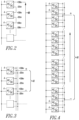
- the typical output voltage of the AC/DC converter 4 is +/- 5 kV to +/- 30 kV and the AC/DC converter 4 can be connected in series ( Figure 2 ), in parallel ( Figure 3 ) or in series and in parallel ( Figure 4 ), in order to scale the output power and/or voltage of the DC output 4B.
- the AC/DC converter 4 increases the HVDC at a rate that will prevent any high voltage transients from forming during the transmission line energization. Being an active converter, the AC/DC converter 4 is capable of shutting down in case of a short circuit fault in the HVDC cable 6 or in the first input portion 8A of the HVDC circuit breaker 8.
- a fault current generated due to a short circuit in the transmission line of the HVDC cable 6 or in the HVDC circuit breaker first input portion 8A is contained by the AC/DC converter 4. If there is such a short circuit, then the AC/DC converter power semiconductor switches (not shown) are turned off to prevent excessive energy to flow in the downstream power circuit.
- the AC electrical energy from a generator (not shown) is transformed into DC electrical energy using the AC/DC converter 4, which can be implemented using diodes or active semiconductor switches (not shown).
- the AC/DC converter 4 can have its DC output voltage slowly climb from zero to its rated value (e.g., without limitation, 60 kVDC), although the methods used for each type to achieve the slow output voltage climb are very distinct.
- the speed of the voltage climb affects the number of frequency components applied to the transmission line of the HVDC cable 6. The faster the voltage climb is, the higher its frequency components.
- High frequency voltage content will cause the transmission line reactive components to generate voltage transients that normally reach twice the applied voltage (e.g., in the example of a 60 kVDC transmission voltage, the voltage spike generated by a fast voltage climb is about 120 kVDC). This will play havoc with the life of the components in the transmission lines as well as over stress the cable insulation.
- the disclosed concept reduces the AC/DC converter output DC voltage climb from zero to rated value. This DC voltage climb rate can be adjusted to the cable type and transmission line length if the fastest possible voltage climb is desired or to a predetermined longer rate that will cover any cable type and length.
- the AC/DC converter 4 is an active converter structured to shut down responsive to a short circuit condition operatively associated with the HVDC cable 6 and/or the circuit breaker 8, and structured to ramp the DC voltage at the DC output 4B thereof at a predetermined rate (e.g., without limitation, 10 kVdc per second for distances up to 100 km; 10 kVdc per two seconds for distances from 100 km to 200 km; 10 kVdc per three seconds for distances greater than 200 km) from zero volts to a suitable HVDC.
- a predetermined rate e.g., without limitation, 10 kVdc per second for distances up to 100 km; 10 kVdc per two seconds for distances from 100 km to 200 km; 10 kVdc per three seconds for distances greater than 200 km.
- a predetermined rate e.g., without limitation, 10 kVdc per second for distances up to 100 km; 10 kVdc per two seconds for distances from 100 km to 200 km; 10
- the HVDC cable 6 employs bipolar transmission, and can be partially above ground and partially below ground, partially above sea and partially subsea, entirely subsea, or entirely below ground.
- Figure 5 shows another system 2' in which the HVDC cable 6' is partially above sea and partially subsea. No unipolar transmission is allowed in subsea or below ground applications due to galvanic corrosion of components of the enclosures involved.
- the HVDC circuit breaker 8 includes a cable pre-charge function to prevent high voltage transients in the transmission line of the HVDC cable 10.
- the HVDC circuit breaker 8 protects a number of branch circuits (e.g., Figure 5 shows a plurality of branch circuits of plural HVDC cables 10) derived off of the main HVDC transmission line of HVDC cable 6', and pulse width modulates the output 8B to charge the downstream load side transmission line of the HVDC cable 10 to prevent high voltage transients due to cable length.
- a fault current generated due to a short circuit in the transmission line of the HVDC cable 10 or the input 12A of the galvanically isolated DC/DC buck converter 12 will be contained and isolated by the HVDC circuit breaker 8.
- the DC circuit breaker solid-state switches e.g., 26 of Figure 16 ) are turned off to protect the downstream power circuit from excessive energy.
- the transmission line of the HVDC cable 10 contains resistive 10R, inductive 10L and capacitive 10C components ( Figure 16 ).
- the impedance values of these components are proportional to the cable length.
- the cable resistive and inductive components limit the current magnitude and its rate of change while its capacitive component stores the electric charge transferred by the voltage pulse and defines a voltage magnitude across the cable terminals 10T ( Figure 16 ).
- the magnitude of the current and how quickly it climbs from zero to its rated value is defined by its resistance and inductance
- the amount of voltage across the cable terminals 10T is defined by the cable capacitance.
- the current in the HVDC cable 10 climbs from zero to a maximum value.
- the rate of the current climb is limited by the cable inductance. If the voltage pulse is long enough, such that the current will reach its maximum value, this maximum value is defined by the cable resistance.
- this current flows, in time, it defines an electric charge that is accumulated in the cable capacitance and is reflected in the cable terminals 10T with a voltage magnitude.
- a minimum voltage increase can be calculated across the cable terminals 10T when a given voltage pulse is applied. This means that with a given voltage pulse width, a minimum voltage should appear at the cable terminals 10T. If the voltage does not appear or is smaller than the calculated value, it means that there is a short circuit in the transmission line or at the load input.
- a fault in the system 2 can be detected without allowing hundreds or thousands of amperes to flow in the transmission line of the HVDC cable 10 before the fault is detected.
- This is called a look ahead function (e.g., function 22 of Figures 13-16 ), which looks for the fault before fully energizing the transmission line.
- the hybrid HVDC circuit breaker 8 provides both a short circuit detection, look ahead function 22 and a cable pre-charge function 24.
- the circuit breaker 8 includes a solid-state switch 26 in series with an electromechanical switch 28.
- the electromechanical switch 28 is employed solely to galvanically isolate the upstream primary circuit 27 from the downstream secondary circuit 29 being switched on or off solely when no electric current is flowing through it, since the solid-state switch 26 can have leakage current flowing through its semiconductor junction when it is turned off.
- solid-state switches e.g., without limitation, IGBT; IGCT
- IGBT IGBT
- IGCT IGCT
- the circuit breaker 8 includes an inductor 30 in series with the solid-state switch 26 and the electromechanical switch 28 to limit the rate of change of the current. Utilizing the switching speed of the solid-state switch 26 and the inductor 30, a relatively simple but effective control strategy is employed to detect a short circuit or a relatively low insulation value in the DC power circuit under protection, such as the example load 29.
- Cable transmission lines exhibit an impedance which is composed of inductive, capacitive and resistive components. If the load end is disconnected or the load equipment is turned off, when the circuit breaker 8 is turned on, the DC power source at 27 has to first charge the capacitance of the transmission line of the HVDC cable 10 to reach the source voltage level.
- Equation 1 The differential equation that defines the voltage across the transmission line capacitance as a function of the injected DC current is shown in Equation 1.
- Cc * dV / dt i wherein:
- the voltage step dV can be determined by turning the solid-state switch 26 on and then off by a known amount of time using Equation 2.
- the current impulse amplitude can be controlled through the inductors 30 by turning the solid-state switches 26 on and then measuring and monitoring the current amplitude by a controller 32 using current sensor 34.
- the controller 32 turns off the solid-state switches 26.
- the monitored voltage step starts to decay within a few seconds, as detected by the controller 32, then this means that there is a current leakage due to an insulation degradation somewhere in the downstream power circuit (e.g., in the HVDC cable 10 or any downstream load such as the DC/DC converter 12).
- the disclosed concept uses the controller 32 with the above capabilities to generate the current impulse, limit the current amplitude, and measure and monitor the voltage step as a consequence of the current impulse.
- the measurement of current and voltage can be achieved using any suitable current and voltage sensors, such as 34,36.
- the controller 32 By verifying that the voltage step is present and that it does not change within a couple of seconds, the controller 32 infers that the cable insulation is healthy and that no short circuit is present. This is the look ahead function 22.
- the electromechanical isolation switch 28 is in series with the solid-state switch 26, such as for example and without limitation, a power semiconductor switch.
- the solid-state switch 26 controls and protects against overload and fault currents while the electromechanical switch 28 is used to isolate the downstream protected branch circuit 29 from the upstream power circuit 27 or mains.
- the electromechanical switch 28 opens and closes at no load.
- the series combination of the switches 26,28 is electrically connected between first input portion 8A and the second output portion 8B of the HVDC circuit breaker 8. When both of the switches 26,28 are closed, the second portion 8B charges the downstream HVDC cable 10 to or toward a HVDC.
- the controller 32 forms a modulation element structured to repetitively turn on and turn off the solid-state switch 26 when the electromechanical isolation switch 28 is closed, in order to control charging of the downstream HVDC cable 10 from zero volts to a HVDC from the first input portion 8A of the HVDC circuit breaker 8.
- This modulation element ramps a duty cycle of the solid-state switch 26 being on from zero to one hundred percent, as will be described.
- the controller 32 also provides a trip mechanism structured to detect a fault downstream of the second output portion 8B of the HVDC circuit breaker 8 responsive to a failure to charge the downstream HVDC cable 10.
- the trip mechanism applies a predetermined current pulse and detects a corresponding predetermined voltage increase of a voltage of the downstream HVDC cable 10.
- the failure to charge can be caused by a short circuit or an insulation failure of the downstream HVDC cable 10.
- the circuit breaker 8 also includes the cable pre-charge function 24.
- the disclosed hybrid DC circuit breaker 8 can be used to charge the cable capacitance Cc by utilizing the relatively fast switching capability of the solid-state switches 26 and the current limiting characteristic of the inductors 30.
- the controller 34 After the controller 34 verifies that there is no short circuit and no cable insulation degradation, the controller 34 employs further current impulses to continue to charge the cable capacitance Cc, such as formed by the distributed capacitance components 10C. Then, after the controller 34 detects that the HVDC cable 10 is fully charged, the solid-state switches 26 will remain turned on.
- a relatively longer HVDC cable 10 will take relatively more current impulses and will take a relatively longer time to charge to the rated source DC voltage with the solid-state switches 26.
- the controller 32 predefines the current impulse frequency and duty cycle, and then adjusts them by the thermal capacity of the hybrid circuit breaker 8 and by the solid-state switch maximum current capability.
- the current impulse amplitude should be equal to or smaller than the solid-state switch maximum current, and the frequency of the impulses should not be so high that it will cause the solid-state switches 26 to overheat.
- the voltage source 27 provides a relatively constant DC voltage amplitude to the HVDC cable 10 and to the downstream load 29 via the hybrid circuit breaker 8 as long as its output current capability is not exceeded.
- the disclosed concept can be employed for both unipolar and bipolar DC power transmission even though for subsea or underground applications the system should be bipolar to avoid galvanic corrosion effects when using the ground or the water as the return path for the electric DC current.
- Unipolar is the transmission mode where the earth (or sea water) is used as the return path. In this case, only one pole is transmitted in an isolated cable.
- the return path is usually a buried graphite rod (not shown) on both ends of the transmission line coupled to a cable (not shown) that is then electrically connected to the equipment, such as 29.
- the bipolar transmission mode shown in Figure 16 , uses two conductor cables 38,40, one for the positive pole and one for the negative pole.
- Every DC current impulse from the HVDC circuit breaker 8 adds to the cable voltage by accumulating electric charge in the cable capacitance Cc (Equation 2), but the impulse duration is short enough to prevent the current from reaching an amplitude that will cause high voltage transients.
- the current amplitude is advantageously limited by: (1) the impulse duration (which is controlled by the controller 32); (2) the HVDC bus voltage amplitude; and (3) the inductance of the inductors 30 (e.g., reactors).
- the cable capacitance Cc varies linearly with the cable length and, thus, as the cable length increases, the cable capacitance Cc increases proportional to the length increase. For a given current impulse (amplitude and time), the voltage across the cable terminals 10T decreases inversely proportional to the cable length increase.
- the controller 32 can suitably adjust the current impulse to achieve the ideal or desired cable charging time.
- Figure 13 shows the first pulse 42 of a pre-charge cycle 43 of the pre-charge function 24, which is also employed for the short circuit detection, look ahead function 22 of Figure 16 .
- the desired DC bus voltage in this example is 60 kVDC.
- the first plot 44 shows the DC bus voltage after the circuit breaker 8 switches at the cable input 10A.
- the example voltage reached after the first pulse 42 of the second plot 46 is 2.6 kVDC. Otherwise, if the cable insulation is compromised, then this voltage will decrease rapidly.
- the second plot 46 shows the voltage pulse 42 generated when the circuit breaker solid-state switches 26 are turned on and then off.
- the example voltage pulse amplitude is 60 kVDC.
- the third plot 48 shows the current pulse 49 generated by the voltage pulse 42 and through the inductors 30.
- the example current pulse amplitude of 200 A is limited by the controller 32.
- the fourth plot 50 shows the circuit breaker solid-state switches 26 gate command signal 52 from the controller 32.
- Figure 14 shows the first fifty example pulses 54 of the pre-charge cycle 43.
- the DC bus voltage before the circuit breaker 8 switches in this example is 60 kVDC.
- the first plot 56 shows the DC bus voltage after the circuit breaker 8 switches at the cable input 10A.
- the example voltage reached after the first fifty example pulses 54 is 9 kVDC.
- the second plot 58 shows the voltage pulses 54 generated when the circuit breaker solid-state switches 26 are turned on and then off.
- the example voltage pulse amplitude is 60 kVDC.
- the third plot 60 shows the current pulses 61 generated by the voltage pulses 54 and through the inductors 30.
- the example current pulse amplitude of 200 A is limited by the controller 32.
- the fourth plot 62 shows the circuit breaker solid-state switches 26 gate command signals 52 from the controller 32.
- Figure 15 shows the full pre-charge cycle 43.
- the DC bus voltage before the circuit breaker 8 switches in this example is 60 kVDC.
- the first plot 64 shows the DC bus voltage after the circuit breaker 8 switches at the cable input 10A. The voltage reached after the pre-charge cycle is 60 kVDC.
- the second plot 66 shows the voltage pulses 54 generated when the circuit breaker solid-state switches 26 are turned on and then off. The voltage pulse amplitude is 60 kVDC.
- the third plot 68 shows the current pulses 69 generated by the voltage pulses 54 and through the inductors 30. The current pulse amplitude of 200 A is limited by the controller 32.
- the fourth plot 70 shows the circuit breaker solid-state switches 26 gate command signal 52 from the controller 32. The command signal 52 stays high or turned-on fully at 71 after the pre-charge cycle 43 is complete.
- the inductors 30 of Figure 16 are not needed per se because the cable inductance will limit the di/dt. However, the inductors 30 are paramount during a short-circuit (e.g., without limitation, directly right at the output 8B of the HVDC circuit breaker 8 in which case no cable inductance will limit the di/dt).
- the cable pre-charge function 24 of the HVDC circuit breaker 8 prevents high voltage transients in the HVDC transmission line of the HVDC cable 10.
- the DC energy from the output 4B of the AC/DC converter 4 is transmitted to the HVDC circuit breaker 8 via the HVDC cable 6 (e.g., without limitation, which can be dozens of miles long).
- the voltage transient in this segment while it is energized is mitigated by the relatively slow climb of the AC/DC converter output voltage.
- This potential arrives at the input 8A of the HVDC circuit breaker 8 whose output 8B feeds the HVDC cable 10 that feeds the corresponding galvanically isolated DC/DC converter 12, which powers the corresponding DC/AC voltage source inverter 14.
- the output 8B of the HVDC circuit breaker 8 is not switched on normally. Instead, the HVDC circuit breaker solid-state switches 26 are commanded on and off at relatively very short time segments.
- the solid-state switches 26 intended for the use in 60 kVDC circuit breakers can be switched on or off within a few microseconds. This feature allows for the HVDC circuit breaker output 8B to be modulated to permit a controlled charging of the cable capacitance Cc and consequently a slow climb of the cable voltage to avoid the two times voltage transient.
- the HVDC circuit breaker 8 can also detect a fault in the transmission line of the HVDC cable 10 or at the input 12A of the DC/DC converter 12 by turning on and off. Therefore, the pre-charge and the look ahead functions are operating simultaneously.
- the controller 32 limits the current to 200 A or less when the 60 kVdc voltage is switched on and off, and the current derivative is limited by the inductors 30 in series with both positive and negative cables.
- dt di * L / 60 kVdc ⁇ Vc
- dt represents the on-time of the circuit breaker solid-state switch 26 and, thus, with the corresponding off-time, defines the modulation duty cycle.
- the difference (60 kVdc - Vc) diminishes, which increases dt and, thus, the duty cycle.
- Vc reaches 60 kVdc
- the difference (60 kVdc - Vc) equals zero and dt goes to infinity, which means that the solid-state switch 26 is continuously turned on.
- the galvanically isolated buck DC/DC converter 12 allows for the motor output 14B of the DC to AC voltage source inverter 14 to have one of its three phases grounded.
- the DC/DC converter 12 is isolated and reduces the HVDC coming from the source to a DC voltage level that is compatible with the motor insulation rating. This reduced voltage is fed into the input DC bus 14A of the DC/AC voltage source inverter 14 whose output 14B feeds the AC transmission line 16 and subsequently the AC motor 18.
- the galvanic isolation reduces the effective zero sequence currents that may flow to the three-phase cable 16 and the AC motor 18. This isolation allows shorting to ground of one of the motor phases with no operational interruption.
- the DC/AC voltage source inverter 14 is an active converter and, thus, the output 14B thereof is protected against short circuit faults.
- the galvanically isolated DC/DC buck converter 12 in the same enclosure 20 as the DC/AC voltage source inverter 14 allows for the transmission of power at high voltage up to the input 14A of the voltage source inverter 14, which reduces the current levels and consequently the voltage transients due to current changes in the HVDC transmission line of the HVDC cable 10 and better utilization of the cable conductor cross section. Also, a fault current generated due to a short circuit in the input 14A of the voltage source inverter 14 will be contained by the DC/DC buck converter 12.
- the high power AC motor 18 is designed for medium voltage to reduce the copper cross section of its windings and of the corresponding supply cable 16.
- the "buck" aspect of the galvanically isolated DC/DC buck converter 12 reduces the high direct current voltage from the corresponding HVDC cable 10 to a medium direct current voltage.
- the AC motors 18 are rated, for example and without limitation, for 4160 V or 6600 V input.
- the insulation rating for a 6600 V motor is 20 kVDC or 14,200 VAC RMS . If power is transmitted from a surface platform (see the AC/DC converter 4 of Figure 5 ) to the motor 18 subsea at about 60 kVDC, then this voltage is three times higher than the motor's insulation voltage rating.
- the 60 kVDC has to be reduced to well below 20 kVDC.
- the inverter 14 For the inverter 14 to produce a 6600 VAC output, its input voltage needs to be around 10 kVDC.
- the DC/DC converter 12 reduces the transmitted 60 kVDC, in this example, to 10 kVDC.
- Subsea cables are relatively expensive, such as about $1000 per meter not counting the installation cost.
- the largest cables for subsea applications would be ideally limited to around 240 square millimeters due to sheer size and weight which affect the cost and difficulty of installation. This means that the electric current is limited by the copper cross section. For 240 square millimeters, the maximum payload current is between 400 A to 500 A depending on the top side and water temperature conditions.
- a high voltage is needed as close to the load 18 as possible, in order to reduce the amount of current in the transmission line and thus reduce the conductor cross section, which in the subsea case, has a limit due to installation restrictions.
- This is provided by the inclusion of the DC/DC buck converter 12 with the inverter 14 whose output 14B feeds the AC motor 18.
- the 60 kVDC is transmitted all the way to the point of delivery and the system 2 can benefit from the lower current up to that point.
- the transmission line can carry 27 megawatts.
- the maximum power transmitted is 4.5 megawatt.
- the galvanically isolated DC/DC buck converter 12 allows for the output to the AC motor 18 to be grounded in one of the phases.
- the system grounding is complex when it comes to DC transmission.
- the generators on a surface platform e.g., Figure 5
- the output of the AC/DC converter 14 is also high impedance grounded via its neutral point.
- a DC/DC converter 12 that is isolated from the source on the platform, it means that the inverter circuit connected to its output 12B is electrically floating with reference to the source. Therefore, if any one of the inverter's output terminals 14B is connected to ground, then there is no ground current that flows in the source.
- the voltage source inverter 14 inputs from the DC input 14A and outputs AC from the output 14B to the AC motor 18. Due to the possibility of relatively long electrical connections between the inverter output 14B and the AC motor 18, there can be a suitable filter (not shown) to minimize common mode and harmonic currents.
- the inverter 14 protects the three-phase transmission lines 16 and the motor windings (not shown) in case of a short circuit fault.
- the inverter output 14B has a filter (not shown) to suppress the pulse width modulation transients allowing for a relatively long transmission line cable 16 to the AC motor 18.
- the inverter 14 employs a selective harmonic elimination modulation method to minimize the filter size.
- a fault current generated due to a short circuit in the transmission lines 16 or the AC motor 18 will be contained by the inverter 14.
- the voltage source inverter 14 has a relatively large capacitor (not shown) connected between the positive and the negative terminals of its input DC bus 14A.
- a current source inverter does not have such as capacitor, but does have a relatively large inductor (not shown) in series with its DC bus positive and/or negative terminals (not shown) of its input DC bus.
- the distribution system 7 is divided into sections that are protected by different elements in the circuit.
- the AC motor 18 is protected by the inverter 14. If there is a short circuit in the three-phase transmission lines 16 between the inverter 14 and the motor 18 or in the motor 18 itself, then the inverter semiconductor switches (not shown) are turned off to stop the fault current that is detected by the inverter control circuit (not shown).
- the alternating current output 14B of the voltage source inverter 14 can be a low alternating current voltage, a medium alternating current voltage, or a high alternating current voltage.
- the three-phase transmission lines 16 can employ low, medium or high voltage AC.
- the AC motor 18 can be a low, medium or high voltage AC motor, such as a three-phase AC motor.
- the enclosure 20 is preferably compensated for subsea pressure.
- U.S. Patent No. 6,822,866 discloses a power conversion system that is void of air by the vacuuming and immersion of power conversion system components in a dielectric gel, oil, gas or in vacuum. This permits the high voltage circuit to become much smaller than it would be in air.
- To build a pressure compensated power conversion system its components are immersed in a fluid that: (1) fills all gaps and voids in the converter structure in order to allow the pressure in the enclosure 20 to be equalized with the external pressure; (2) is dielectric in nature and inert to prevent chemical corrosion of components immersed therein; and (3) transports heat energy generated in the DC/DC converter components to the walls (not shown) of the enclosure 20.
- the disclosed concept permits the cable size of the three-phase transmission lines 16 to be relatively smaller and to get increasingly smaller as it gets closer to the AC motor 18 due to the decreasing sea water temperature as the cable goes deeper.
- One umbilical cable is for 20,000 MW (e.g., maximum cable size has to do with its temperature rating and the limitations imposed by the I-tube (e.g., without limitation, a straight vertical tube that is typically 220 feet long, encases the power cable (or "umbilical”), is physically attached to the platform structure, and protects the cable against sea-induced motions), which supports and holds the cable that leaves the oil platform at sea level as it goes down into the sea bed; there is a length of cable that the I-tube grabs and thus constrains the cable cooling and thus requires the worst case conductor cross section; as the transmission line increases in the subsea region, the water temperature drops dramatically and the cable could have its conductor cross section reduced from a given splice point).
- the disclosed concept can employ a surface or sea-bed installed AC to DC (typically 10 kVDC to 240 kVDC scalable) two-wire (+, - configured) power conversion assembly fed by a single umbilical cable to a HVDC switchgear assembly comprised of one or multiple solid-state protected and controlled HVDC circuit breakers 8 in a pressure compensated enclosure (not shown but see Example 9) to withstand, for example, a minimum of 300 bar of pressure and 3 kM of sea water depth.
- AC to DC typically 10 kVDC to 240 kVDC scalable
- HVDC switchgear assembly comprised of one or multiple solid-state protected and controlled HVDC circuit breakers 8 in a pressure compensated enclosure (not shown but see Example 9) to withstand, for example, a minimum of 300 bar of pressure and 3 kM of sea water depth.
- the individual sea-bed switchgear breakers 8 or single group mounted switchgear breakers 8 could feed various AC or DC loads, such as the example AC motors 18, on the sea-bed including the voltage source inverter 14 up to and exceeding 13.8 kVAC output voltage.
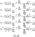
- Figures 6A-6B show an example distribution system 7 according to the disclosed concept, as powered by the AC/DC converter 4 and the HVDC cable 6, including the subsea switch gear 8, plural cables 10, plural drives each formed by the DC/DC buck converter 12 and the voltage source inverter 14, plural cables 16 and plural AC motors 18.
- Example electrical and cable parameters are also shown. Due to the example system disclosed here, the transmission and distribution cables never conduct a current higher than the 450 A limit.
- Figures 7 and 8 show differences between a prior system 2' and a non-limiting example of the disclosed system 2, except simplified to remove the HVDC circuit breaker 8.
- the case in Figure 7 shows the consequence of reducing the DC voltage midway and the other case in Figure 8 shows the advantages of having the DC/DC converter 12 in the same enclosure 20 ( Figure 1 ) as the inverter 14.
- the example cable parameters accurately reflect real world parameters.
- the AC/DC converter 4 transmits 132 kVdc and 401 A via a 270 mile cable in Figure 7 and a 309 mile cable in Figure 8 . Due to the resistive losses in the cable in Figure 7 , the input voltage at the input of the DC/DC converter 12 is 97.9 kV while in Figure 8 it is 92.9 kVdc.
- the high DC voltage on the HVDC cable 10 up to the drive enclosure 20 in Figure 8 which includes the buck DC/DC converter 12 (which reduces 92.9 kVDC to 11 kVDC), this avoids any substantial length of cable 13'
- Figures 9-12 show modular distribution systems 100,200,300,400, respectively.
- FIG 9 shows a supply cable 102 (e.g., such as HVDC cable 6 of Figure 1 ) electrically connected to a line (e.g., supply) plug 104 of a single circuit breaker enclosure 106 having three example branch circuit breakers 108,110,112, each of which has a load plug 114,116,118, respectively.
- the example branch circuit breakers 108,110,112 are HVDC circuit breakers, the same as or similar to the HVDC circuit breaker 8 of Figure 1 , and are enclosed by the example single enclosure 106.
- the single line plug 104 is externally electrically connected to the opposite second end 120 of the HVDC cable 102 and is internally electrically connected to a first input portion 124 of the HVDC circuit breakers 108,110,112.
- Each of the load plugs 114,116,118 is externally electrically connected to a first input end 126 of a corresponding HVDC cable 128.
- Figure 10 shows the supply cable 202 electrically connected to a line (e.g., supply) plug 204 of a distribution module 206 having an input 207 and three example output plugs 208,210,212, each of which engages a separate HVDC branch circuit breaker 214,216,218, each of which has a load plug 220 and is enclosed by a corresponding enclosure 215,217,219, respectively.
- a line e.g., supply
- a distribution module 206 having an input 207 and three example output plugs 208,210,212, each of which engages a separate HVDC branch circuit breaker 214,216,218, each of which has a load plug 220 and is enclosed by a corresponding enclosure 215,217,219, respectively.
- Figure 11 is similar to Figure 10 except that the distribution module 206' is interconnected with the HVDC branch circuit breakers 214,216,218 by three external cables 302,304,306, respectively.
- the distribution module 206' has an input 308 electrically connected to the opposite second end 310 of the supply cable 202 and a plurality of outputs 312,314,316. Each of the outputs 312,314,316 is electrically connected to the input portion 318 of a corresponding one of the HVDC circuit breakers 214,216,218.
- Figure 12 shows a supply cable 402 electrically connected to a line (e.g., supply) plug 410 of a circuit breaker enclosure 406 having one branch circuit breaker 408 including the line plug 410, a load plug 412 and a daisy chain plug 414.
- a line e.g., supply
- Two other circuit breaker enclosures 416,418, each having one branch circuit breaker 420 including a line plug 422, a load plug 424 and a daisy chain plug 426, are interconnected with the first circuit breaker enclosure 406 by daisy chain cables 428 electrically connected between the daisy chain plug 414 or 426 of a prior circuit breaker enclosure 406,416 and the line plug 422 of another circuit breaker enclosure 416,418.
- the line plug 410 of the enclosure 406 is externally electrically connected to the opposite second end 404 of the HVDC cable 402 and internally electrically connected to the plug 414 and the input portion 408A of the HVDC circuit breaker 408.
- the jumper cables 428 electrically connect the plugs 414 and 422 or 426 and 422.
- Each of the load plugs 412,424 is externally electrically connected to the first end 430 of a corresponding HVDC cable 432.
Landscapes
- Engineering & Computer Science (AREA)
- Power Engineering (AREA)
- Direct Current Feeding And Distribution (AREA)
- Inverter Devices (AREA)
- Dc-Dc Converters (AREA)
- Distribution Board (AREA)
Abstract
Description
- This application claims priority from and claims the benefit of
U.S. Patent Application Serial No. 13/901,770, filed May 24, 2013 - The disclosed concept pertains generally to power distribution and, more particularly, to high voltage direct current transmission and distribution systems, such as, for example, such systems for above ground, below ground or subsea applications. The disclosed concept further pertains to circuit interrupters for high voltage direct current distribution systems.
- Alternating current (AC) power distribution systems are well known.
- High voltage, direct current (DC) power distribution systems have less energy losses and require less costly transmission cables than corresponding AC distribution systems. In long transmission lines and, in particular, in ones that use cable, high voltage DC power transmission may be the only feasible method of power transmission because using AC will cause debilitating instability and excessive losses.
- When connecting a DC voltage source to a relatively long cable transmission line when the cable capacitance is discharged, relatively large oscillatory currents occur which, in turn, generate relatively large voltage spikes along the cable length. These voltage spikes can compromise the insulation of the cable itself as well as the insulation of any device electrically connected thereto.
- Furthermore, the relatively large oscillatory currents can cause nuisance tripping of protection devices of the transmission line.
- There is room for improvement in high voltage direct current transmission and distribution systems specifically regarding, for example, the cable charging process when the transmission line is energized.
- There is also room for improvement in circuit interrupters for such systems.
- These needs and others are met by embodiments of the disclosed concept in which a direct current to alternating current voltage source inverter is mounted in an enclosure with a corresponding galvanically isolated direct current to direct current converter, in order that a direct current output of the galvanically isolated direct current to direct current converter is directly electrically connected within the enclosure to the direct current input of the direct current to alternating current voltage source inverter.
- These needs and others are also met by embodiments of the disclosed concept in which a circuit interrupter for a power circuit of a high voltage direct current distribution system comprises a controller cooperating with the series combination of a solid-state switch and an electromechanical isolation switch to open, close and trip open the power circuit, the controller being structured to repetitively turn on and turn off the solid-state switch when the electromechanical isolation switch is closed, in order to control charging of the power circuit from zero volts to a high direct current voltage.
- In accordance with one aspect of the disclosed concept, a high voltage direct current transmission and distribution system comprises: an alternating current to direct current converter including an alternating current input and a direct current output; a first high voltage direct current cable including a first end electrically connected to the direct current output of the alternating current to direct current converter and an opposite second end; and a distribution system comprising: a number of high voltage direct current circuit breakers, each of the number of high voltage direct current circuit breakers including a first portion electrically connected to the opposite second end of the first high voltage direct current cable and a second portion; a number of second high voltage direct current cables, each of the number of second high voltage direct current cables including a first end electrically connected to the second portion of a corresponding one of the number of high voltage direct current circuit breakers and an opposite second end; a number of galvanically isolated direct current to direct current converters, each of the number of galvanically isolated direct current to direct current converters including a direct current input electrically connected to the opposite second end of a corresponding one of the number of second high voltage direct current cables and a direct current output; a number of direct current to alternating current voltage source inverters, each of the number of direct current to alternating current voltage source inverters including a direct current input electrically connected to the direct current output of a corresponding one of the number of galvanically isolated direct current to direct current converters and an alternating current output; a number of alternating current transmission lines, each of the number of alternating current transmission lines including a first end electrically connected to the alternating current output of a corresponding one of the number of direct current to alternating current voltage source inverters and an opposite second end; and a number of alternating current loads, each of the number of alternating current loads electrically connected to the opposite second end of a corresponding one of the number of alternating current transmission lines, wherein each of the number of direct current to alternating current voltage source inverters is mounted in an enclosure with a corresponding one of the number of galvanically isolated direct current to direct current converters, in order that the direct current output of the last such corresponding one of the number of galvanically isolated direct current to direct current converters is directly electrically connected within the enclosure to the direct current input of a corresponding one of the number of direct current to alternating current voltage source inverters.
- As another aspect of the disclosed concept, a direct current to alternating current inverter sub-system is for a high voltage direct current distribution system. The direct current to alternating current inverter sub-system comprises: an enclosure; a direct current to direct current galvanically isolated buck converter including a direct current input electrically connectable to a high voltage direct current cable and a direct current output; and a direct current to alternating current voltage source inverter including a direct current input electrically connected to the direct current output of the direct current to direct current galvanically isolated buck converter and an alternating current output electrically connectable to an alternating current transmission line, wherein the direct current to alternating current voltage source inverter is mounted in the enclosure with the direct current to direct current galvanically isolated buck converter, in order that the direct current output of the direct current to direct current galvanically isolated buck converter is directly electrically connected within the enclosure to the direct current input of the direct current to alternating current voltage source inverter.
- As another aspect of the disclosed concept, a circuit interrupter for a power circuit of a high voltage direct current distribution system comprises: a first terminal; a second terminal; an electromechanical isolation switch; a solid-state switch electrically connected in series with the electromechanical isolation switch between the first and second terminals; and a controller cooperating with the solid-state switch and the electromechanical isolation switch to open, close and trip open the power circuit, the controller being structured to repetitively turn on and turn off the solid-state switch when the electromechanical isolation switch is closed, in order to control charging of the power circuit from zero volts to a high direct current voltage.
- A full understanding of the disclosed concept can be gained from the following description of the preferred embodiments when read in conjunction with the accompanying drawings in which:
-
Figure 1 is a block diagram of an example high voltage direct current (HVDC) transmission and distribution system in accordance with embodiments of the disclosed concept. -
Figure 2 is a block diagram showing a plurality of alternating current to direct current (AC/DC) converters electrically connected in series for use with the HVDC transmission and distribution system ofFigure 1 . -
Figure 3 is a block diagram showing a plurality of AC/DC converters electrically connected in parallel for use with the HVDC transmission and distribution system ofFigure 1 . -
Figure 4 is a block diagram showing a plurality of AC/DC converters electrically connected in parallel and series for use with the HVDC transmission and distribution system ofFigure 1 . -
Figure 5 is a block diagram of another example HVDC transmission and distribution system for subsea applications in accordance with another embodiment of the disclosed concept. -
Figures 6A-6B form a block diagram of another example HVDC transmission and distribution system for subsea applications in accordance with another embodiment of the disclosed concept. -
Figure 7 is a block diagram of an HVDC transmission and distribution system for subsea applications. -
Figure 8 is a block diagram of another example HVDC transmission and distribution system for subsea applications in accordance with another embodiment of the disclosed concept. -
Figures 9-12 are block diagrams of modular circuit breaker distribution mechanisms for use with the HVDC transmission and distribution system ofFigure 1 . -
Figures 13-15 are plots of DC bus voltage, a number of generated voltage pulses, a number of generated current pulses, and a number of gate command signals for different portions of a pre-charge cycle of a HVDC circuit breaker in accordance with another embodiment of the disclosed concept. -
Figure 16 is a block diagram in schematic form of a HVDC circuit breaker in accordance with another embodiment of the disclosed concept. - As employed herein, the term "number" shall mean one or an integer greater than one (i.e., a plurality).
- As employed herein, the statement that two or more parts are "connected" or "coupled" together shall mean that the parts are joined together either directly or joined through one or more intermediate parts.
- As employed herein, the term "low voltage" shall mean any alternating current voltage that is less than about 1000 VRMS (i.e., a low alternating current voltage), or any direct current voltage that is less than about 1500 VDC (i.e., a low direct current voltage).
- As employed herein, the term "medium voltage" shall mean any alternating current voltage greater than a low alternating current voltage and in the range from about 1 kVRMS to about 38 kVRMS (i.e., a medium alternating current voltage), or any direct current voltage greater than a low direct current voltage and in the range from about 1500 VDC to about 50 kVDC (i.e., a medium direct current voltage).
- As employed herein, the term "high voltage" shall mean any suitable alternating current voltage greater than a medium alternating current voltage (i.e., a high alternating current voltage), or any suitable direct current voltage greater than a medium direct current voltage (i.e., a high direct current voltage). A high direct current voltage is also equivalently referred to as high voltage direct current (HVDC) herein.
- Referring to
Figure 1 , a high voltage direct current (HVDC) transmission anddistribution system 2 includes an alternating current to direct current (AC/DC)converter 4, anHVDC cable 6, and adistribution system 7 including a number ofHVDC circuit breakers 8 for a number of branch loads, a number ofHVDC transmission lines 10, a number of galvanically isolated direct current to direct current (DC/DC)converters 12, a number ofvoltage source inverters 14, a number of three-phase transmission lines 16, and a number of AC loads, such as a number ofAC motors 18. - In one example embodiment, the AC/
DC converter 4 and a portion of theHVDC cable 6 are above the surface of the sea or above ground, and the remaining portion and the rest of thesystem 2 are subsea or below ground. - In another example embodiment, all of the
system 2 is subsea or below ground. - The AC/
DC converter 4 includes anAC input 4A and aDC output 4B. The HVDCcable 6 includes afirst end 6A electrically connected to theDC output 4B of the AC/DC converter 4 and an oppositesecond end 6B. Each of the number ofHVDC circuit breakers 8 includes afirst portion 8A electrically connected to the oppositesecond end 6B of theHVDC cable 6 and asecond portion 8B. Each of the number ofHVDC cables 10 includes afirst end 10A electrically connected to thesecond portion 8B of a corresponding one of the number ofHVDC circuit breakers 8 and an oppositesecond end 10B. The number of DC/DC converters 12 are galvanically isolated to avoid ground currents in relatively long HVDC cables, such as 10, and to permit the grounding of one of the phases of the DC toAC output 14B. Each of the number of galvanically isolated DC/DC converters 12 includes aDC input 12A electrically connected to the oppositesecond end 10B of a corresponding one of the number ofHVDC cables 10 and theDC output 12B. Each of the number of DC/ACvoltage source inverters 14 includes aDC input 14A electrically connected to theDC output 12B of a corresponding one of the number of galvanically isolated DC/DC converters 12 and anAC output 14B. Each of the number ofAC transmission lines 16 includes afirst end 16A electrically connected to theAC output 14B of a corresponding one of the number of DC/ACvoltage source inverters 14 and an oppositesecond end 16B. Each of the number ofAC loads 18 is electrically connected to the oppositesecond end 16B of a corresponding one of the number ofAC transmission lines 16. Each of the number of DC/ACvoltage source inverters 14 is mounted in anenclosure 20 with a corresponding one of the number of galvanically isolated DC/DC converters 12, in order that theDC output 12B thereof is directly electrically connected within theenclosure 20 to theDC input 14A of a corresponding one of the number of DC/ACvoltage source inverters 14. - The AC/
DC converter 4 can be installed on or above the surface of the sea or underwater (e.g., subsea) and is structured to ramp the DC voltage of theDC output 4B at a limited rate in order to avoid high voltage transients in the transmission line of theHVDC cable 6 during its energization. In the case of underwater installation, there is an isolation transformer (not shown) on a platform (not shown) and a multi-pulse transformer and converter (not shown) underwater. This configuration minimizes the ground current at the source. - The
HVDC circuit breaker 8, theHVDC cable 10, the galvanically isolated DC/DC converter 12, the DC/ACvoltage source inverter 14, theenclosure 20, theAC transmission line 16, and theAC load 18 are either subsea or below ground. - As a non-limiting example, the typical output voltage of the AC/
DC converter 4 is +/- 5 kV to +/- 30 kV and the AC/DC converter 4 can be connected in series (Figure 2 ), in parallel (Figure 3 ) or in series and in parallel (Figure 4 ), in order to scale the output power and/or voltage of theDC output 4B. The AC/DC converter 4 increases the HVDC at a rate that will prevent any high voltage transients from forming during the transmission line energization. Being an active converter, the AC/DC converter 4 is capable of shutting down in case of a short circuit fault in theHVDC cable 6 or in thefirst input portion 8A of theHVDC circuit breaker 8. Hence, a fault current generated due to a short circuit in the transmission line of theHVDC cable 6 or in the HVDC circuit breakerfirst input portion 8A is contained by the AC/DC converter 4. If there is such a short circuit, then the AC/DC converter power semiconductor switches (not shown) are turned off to prevent excessive energy to flow in the downstream power circuit. - The AC electrical energy from a generator (not shown) is transformed into DC electrical energy using the AC/
DC converter 4, which can be implemented using diodes or active semiconductor switches (not shown). Normally, amulti-pulse AC input 4A is employed in order to reduce the harmonic distortion footprint in the utility. Whether it uses the diodes or the active semiconductor switches, such as IGBTs, the AC/DC converter 4 can have its DC output voltage slowly climb from zero to its rated value (e.g., without limitation, 60 kVDC), although the methods used for each type to achieve the slow output voltage climb are very distinct. The speed of the voltage climb affects the number of frequency components applied to the transmission line of theHVDC cable 6. The faster the voltage climb is, the higher its frequency components. High frequency voltage content will cause the transmission line reactive components to generate voltage transients that normally reach twice the applied voltage (e.g., in the example of a 60 kVDC transmission voltage, the voltage spike generated by a fast voltage climb is about 120 kVDC). This will play havoc with the life of the components in the transmission lines as well as over stress the cable insulation. To avoid this high voltage transient, the disclosed concept reduces the AC/DC converter output DC voltage climb from zero to rated value. This DC voltage climb rate can be adjusted to the cable type and transmission line length if the fastest possible voltage climb is desired or to a predetermined longer rate that will cover any cable type and length. - Preferably, the AC/
DC converter 4 is an active converter structured to shut down responsive to a short circuit condition operatively associated with theHVDC cable 6 and/or thecircuit breaker 8, and structured to ramp the DC voltage at theDC output 4B thereof at a predetermined rate (e.g., without limitation, 10 kVdc per second for distances up to 100 km; 10 kVdc per two seconds for distances from 100 km to 200 km; 10 kVdc per three seconds for distances greater than 200 km) from zero volts to a suitable HVDC. The same rates are applicable for theHVDC circuit breaker 8. - The
HVDC cable 6 employs bipolar transmission, and can be partially above ground and partially below ground, partially above sea and partially subsea, entirely subsea, or entirely below ground. For example,Figure 5 shows another system 2' in which the HVDC cable 6' is partially above sea and partially subsea. No unipolar transmission is allowed in subsea or below ground applications due to galvanic corrosion of components of the enclosures involved. - The
HVDC circuit breaker 8 includes a cable pre-charge function to prevent high voltage transients in the transmission line of theHVDC cable 10. TheHVDC circuit breaker 8 protects a number of branch circuits (e.g.,Figure 5 shows a plurality of branch circuits of plural HVDC cables 10) derived off of the main HVDC transmission line of HVDC cable 6', and pulse width modulates theoutput 8B to charge the downstream load side transmission line of theHVDC cable 10 to prevent high voltage transients due to cable length. A fault current generated due to a short circuit in the transmission line of theHVDC cable 10 or theinput 12A of the galvanically isolated DC/DC buck converter 12 will be contained and isolated by theHVDC circuit breaker 8. As a result, the DC circuit breaker solid-state switches (e.g., 26 ofFigure 16 ) are turned off to protect the downstream power circuit from excessive energy. - The transmission line of the
HVDC cable 10 contains resistive 10R, inductive 10L and capacitive 10C components (Figure 16 ). The impedance values of these components are proportional to the cable length. When a voltage pulse is applied to the transmission line, the cable resistive and inductive components limit the current magnitude and its rate of change while its capacitive component stores the electric charge transferred by the voltage pulse and defines a voltage magnitude across thecable terminals 10T (Figure 16 ). For a given cable length, the magnitude of the current and how quickly it climbs from zero to its rated value is defined by its resistance and inductance, and the amount of voltage across thecable terminals 10T is defined by the cable capacitance. - When the voltage pulse is first applied, the current in the
HVDC cable 10 climbs from zero to a maximum value. The rate of the current climb is limited by the cable inductance. If the voltage pulse is long enough, such that the current will reach its maximum value, this maximum value is defined by the cable resistance. As this current flows, in time, it defines an electric charge that is accumulated in the cable capacitance and is reflected in thecable terminals 10T with a voltage magnitude. - By assuming a maximum cable length and, thus, a maximum resistance, inductance and capacitance, a minimum voltage increase can be calculated across the
cable terminals 10T when a given voltage pulse is applied. This means that with a given voltage pulse width, a minimum voltage should appear at thecable terminals 10T. If the voltage does not appear or is smaller than the calculated value, it means that there is a short circuit in the transmission line or at the load input. - It also means that a fault in the
system 2 can be detected without allowing hundreds or thousands of amperes to flow in the transmission line of theHVDC cable 10 before the fault is detected. This is called a look ahead function (e.g., function 22 ofFigures 13-16 ), which looks for the fault before fully energizing the transmission line. The rate of change of the current (di/dt) is defined by the cable inductance (L):
- The steady state current magnitude (i) is defined by the cable resistance (R):

- The voltage (V) produced by the voltage pulse is defined by the cable capacitance (C) and the current that is defined by the cable resistance and inductance:

i ∗ t is calculated from the double time integral of the di/dt = V / L plus the time integral of the current, i = V / R, after the current reaches the rated value defined by R and for the rest of the duration of the voltage pulse. - Referring to
Figures 13-16 , the hybridHVDC circuit breaker 8 provides both a short circuit detection, look ahead function 22 and a cablepre-charge function 24. Thecircuit breaker 8 includes a solid-state switch 26 in series with anelectromechanical switch 28. Theelectromechanical switch 28 is employed solely to galvanically isolate the upstreamprimary circuit 27 from the downstreamsecondary circuit 29 being switched on or off solely when no electric current is flowing through it, since the solid-state switch 26 can have leakage current flowing through its semiconductor junction when it is turned off. The advantage of using solid-state switches (e.g., without limitation, IGBT; IGCT), such as 26, is that they can switch on and off much faster than electromechanical switches, such as 28. For example and without limitation, a high voltage IGBT can turn on or off within five microseconds, while an electromechanical switch can take dozens of milliseconds to do the same. - The
circuit breaker 8 includes aninductor 30 in series with the solid-state switch 26 and theelectromechanical switch 28 to limit the rate of change of the current. Utilizing the switching speed of the solid-state switch 26 and theinductor 30, a relatively simple but effective control strategy is employed to detect a short circuit or a relatively low insulation value in the DC power circuit under protection, such as theexample load 29. - Cable transmission lines exhibit an impedance which is composed of inductive, capacitive and resistive components. If the load end is disconnected or the load equipment is turned off, when the
circuit breaker 8 is turned on, the DC power source at 27 has to first charge the capacitance of the transmission line of theHVDC cable 10 to reach the source voltage level. The differential equation that defines the voltage across the transmission line capacitance as a function of the injected DC current is shown inEquation 1.
- Cc is the cable capacitance which increases linearly with cable length as a function of its distributed
capacitive components 10C; - dV/dt is the derivative of the voltage across the cable positive and
negative terminals 10T; and - i is the current in the
HVDC cable 10. - If the cable capacitance Cc is known, then the voltage step dV can be determined by turning the solid-
state switch 26 on and then off by a known amount oftime using Equation 2. - If the cable capacitance Cc is not known, then the current impulse amplitude can be controlled through the
inductors 30 by turning the solid-state switches 26 on and then measuring and monitoring the current amplitude by acontroller 32 usingcurrent sensor 34. When the current amplitude reaches a predetermined value, which should be equal to or less than the solid-state switch maximum current capability, then thecontroller 32 turns off the solid-state switches 26. The di/dt value is limited by the inductance of the inductors 30 (e.g., L1 and L2) as shown byEquation 3.
- If there is no short circuit between the positive and the
negative cable terminals 10T, then after the current impulse above, there will be a voltage step developed in theHVDC cable 10. This voltage step is then measured and monitored by thecontroller 32 usingvoltage sensor 36. If the voltage is steady, then its value corresponds to the unknown cable capacitance Cc. If a confirmation is needed, then a second current impulse can be injected in the same manner as was described above and the resulting voltage step should be twice as large as the first voltage step. - The above approach can also be used for the known cable capacitance case.
- If the monitored voltage step starts to decay within a few seconds, as detected by the
controller 32, then this means that there is a current leakage due to an insulation degradation somewhere in the downstream power circuit (e.g., in theHVDC cable 10 or any downstream load such as the DC/DC converter 12). - The disclosed concept uses the
controller 32 with the above capabilities to generate the current impulse, limit the current amplitude, and measure and monitor the voltage step as a consequence of the current impulse. The measurement of current and voltage can be achieved using any suitable current and voltage sensors, such as 34,36. - By verifying that the voltage step is present and that it does not change within a couple of seconds, the
controller 32 infers that the cable insulation is healthy and that no short circuit is present. This is the look ahead function 22. - The
electromechanical isolation switch 28 is in series with the solid-state switch 26, such as for example and without limitation, a power semiconductor switch. The solid-state switch 26 controls and protects against overload and fault currents while theelectromechanical switch 28 is used to isolate the downstream protectedbranch circuit 29 from theupstream power circuit 27 or mains. Theelectromechanical switch 28 opens and closes at no load. The series combination of theswitches first input portion 8A and thesecond output portion 8B of theHVDC circuit breaker 8. When both of theswitches second portion 8B charges thedownstream HVDC cable 10 to or toward a HVDC. - The
controller 32 forms a modulation element structured to repetitively turn on and turn off the solid-state switch 26 when theelectromechanical isolation switch 28 is closed, in order to control charging of thedownstream HVDC cable 10 from zero volts to a HVDC from thefirst input portion 8A of theHVDC circuit breaker 8. This modulation element ramps a duty cycle of the solid-state switch 26 being on from zero to one hundred percent, as will be described. - The
controller 32 also provides a trip mechanism structured to detect a fault downstream of thesecond output portion 8B of theHVDC circuit breaker 8 responsive to a failure to charge thedownstream HVDC cable 10. As will be described, the trip mechanism applies a predetermined current pulse and detects a corresponding predetermined voltage increase of a voltage of thedownstream HVDC cable 10. The failure to charge can be caused by a short circuit or an insulation failure of thedownstream HVDC cable 10. - As was indicated above, the
circuit breaker 8 also includes the cablepre-charge function 24. To resolve the problems of nuisance tripping, relatively large oscillatory currents, and relatively large voltage spikes along the cable length when connecting a DC voltage source to a relatively long cable transmission line, the disclosed hybridDC circuit breaker 8 can be used to charge the cable capacitance Cc by utilizing the relatively fast switching capability of the solid-state switches 26 and the current limiting characteristic of theinductors 30. - After the
controller 34 verifies that there is no short circuit and no cable insulation degradation, thecontroller 34 employs further current impulses to continue to charge the cable capacitance Cc, such as formed by the distributedcapacitance components 10C. Then, after thecontroller 34 detects that theHVDC cable 10 is fully charged, the solid-state switches 26 will remain turned on. - A relatively
longer HVDC cable 10 will take relatively more current impulses and will take a relatively longer time to charge to the rated source DC voltage with the solid-state switches 26. - In one embodiment, the
controller 32 predefines the current impulse frequency and duty cycle, and then adjusts them by the thermal capacity of thehybrid circuit breaker 8 and by the solid-state switch maximum current capability. In other words, the current impulse amplitude should be equal to or smaller than the solid-state switch maximum current, and the frequency of the impulses should not be so high that it will cause the solid-state switches 26 to overheat. - In
Figure 16 , thevoltage source 27 provides a relatively constant DC voltage amplitude to theHVDC cable 10 and to thedownstream load 29 via thehybrid circuit breaker 8 as long as its output current capability is not exceeded. - The disclosed concept can be employed for both unipolar and bipolar DC power transmission even though for subsea or underground applications the system should be bipolar to avoid galvanic corrosion effects when using the ground or the water as the return path for the electric DC current. Unipolar is the transmission mode where the earth (or sea water) is used as the return path. In this case, only one pole is transmitted in an isolated cable. The return path is usually a buried graphite rod (not shown) on both ends of the transmission line coupled to a cable (not shown) that is then electrically connected to the equipment, such as 29. The bipolar transmission mode, shown in
Figure 16 , uses twoconductor cables - Every DC current impulse from the
HVDC circuit breaker 8 adds to the cable voltage by accumulating electric charge in the cable capacitance Cc (Equation 2), but the impulse duration is short enough to prevent the current from reaching an amplitude that will cause high voltage transients. The current amplitude is advantageously limited by: (1) the impulse duration (which is controlled by the controller 32); (2) the HVDC bus voltage amplitude; and (3) the inductance of the inductors 30 (e.g., reactors). - The cable capacitance Cc varies linearly with the cable length and, thus, as the cable length increases, the cable capacitance Cc increases proportional to the length increase. For a given current impulse (amplitude and time), the voltage across the
cable terminals 10T decreases inversely proportional to the cable length increase. - This means that for a particular current impulse pattern (if fixed by the controller 32), relatively more impulses are needed to charge the
HVDC cable 10 to its desired or rated voltage as the cable length increases. On the other hand, if the cable capacitance Cc is preloaded (e.g., without limitation, manually) to thecontroller 32, then it can adjust the current impulse to keep the pre-charge time the same. This can also be achieved automatically by applying a predetermined current impulse and expecting an ideal voltage step as a consequence. If the measured voltage is much lower than expected and it does not decay rapidly within a couple of seconds, then this means that the cable capacitance Cc is relatively higher than expected. Otherwise, if the measured voltage is much higher than expected as a consequence of the predetermined current impulse, then this means that the cable capacitance Cc is relatively lower than expected. In either case, thecontroller 32 can suitably adjust the current impulse to achieve the ideal or desired cable charging time. -
Figure 13 shows thefirst pulse 42 of apre-charge cycle 43 of thepre-charge function 24, which is also employed for the short circuit detection, look ahead function 22 ofFigure 16 . The desired DC bus voltage in this example is 60 kVDC. Thefirst plot 44 shows the DC bus voltage after thecircuit breaker 8 switches at thecable input 10A. The example voltage reached after thefirst pulse 42 of thesecond plot 46 is 2.6 kVDC. Otherwise, if the cable insulation is compromised, then this voltage will decrease rapidly. Thesecond plot 46 shows thevoltage pulse 42 generated when the circuit breaker solid-state switches 26 are turned on and then off. The example voltage pulse amplitude is 60 kVDC. Thethird plot 48 shows thecurrent pulse 49 generated by thevoltage pulse 42 and through theinductors 30. The example current pulse amplitude of 200 A is limited by thecontroller 32. Thefourth plot 50 shows the circuit breaker solid-state switches 26gate command signal 52 from thecontroller 32. -
Figure 14 shows the first fiftyexample pulses 54 of thepre-charge cycle 43. Again, the DC bus voltage before thecircuit breaker 8 switches in this example is 60 kVDC. Thefirst plot 56 shows the DC bus voltage after thecircuit breaker 8 switches at thecable input 10A. The example voltage reached after the first fiftyexample pulses 54 is 9 kVDC. Thesecond plot 58 shows thevoltage pulses 54 generated when the circuit breaker solid-state switches 26 are turned on and then off. The example voltage pulse amplitude is 60 kVDC. Thethird plot 60 shows thecurrent pulses 61 generated by thevoltage pulses 54 and through theinductors 30. The example current pulse amplitude of 200 A is limited by thecontroller 32. Thefourth plot 62 shows the circuit breaker solid-state switches 26 gate command signals 52 from thecontroller 32. -
Figure 15 shows the fullpre-charge cycle 43. Again, the DC bus voltage before thecircuit breaker 8 switches in this example is 60 kVDC. Thefirst plot 64 shows the DC bus voltage after thecircuit breaker 8 switches at thecable input 10A. The voltage reached after the pre-charge cycle is 60 kVDC. Thesecond plot 66 shows thevoltage pulses 54 generated when the circuit breaker solid-state switches 26 are turned on and then off. The voltage pulse amplitude is 60 kVDC. Thethird plot 68 shows thecurrent pulses 69 generated by thevoltage pulses 54 and through theinductors 30. The current pulse amplitude of 200 A is limited by thecontroller 32. Thefourth plot 70 shows the circuit breaker solid-state switches 26gate command signal 52 from thecontroller 32. Thecommand signal 52 stays high or turned-on fully at 71 after thepre-charge cycle 43 is complete. - For the pre-charge function to work on a relatively long cable, the
inductors 30 ofFigure 16 are not needed per se because the cable inductance will limit the di/dt. However, theinductors 30 are paramount during a short-circuit (e.g., without limitation, directly right at theoutput 8B of theHVDC circuit breaker 8 in which case no cable inductance will limit the di/dt). - The cable
pre-charge function 24 of theHVDC circuit breaker 8 prevents high voltage transients in the HVDC transmission line of theHVDC cable 10. The DC energy from theoutput 4B of the AC/DC converter 4 is transmitted to theHVDC circuit breaker 8 via the HVDC cable 6 (e.g., without limitation, which can be dozens of miles long). The voltage transient in this segment while it is energized is mitigated by the relatively slow climb of the AC/DC converter output voltage. This potential arrives at theinput 8A of theHVDC circuit breaker 8 whoseoutput 8B feeds theHVDC cable 10 that feeds the corresponding galvanically isolated DC/DC converter 12, which powers the corresponding DC/ACvoltage source inverter 14. - To avoid the same issue described above in connection with the AC/
DC converter 4 ramping the DC voltage at a limited rate as to avoid high voltage transients in the transmission line of theHVDC cable 6, theoutput 8B of theHVDC circuit breaker 8 is not switched on normally. Instead, the HVDC circuit breaker solid-state switches 26 are commanded on and off at relatively very short time segments. The solid-state switches 26 intended for the use in 60 kVDC circuit breakers can be switched on or off within a few microseconds. This feature allows for the HVDCcircuit breaker output 8B to be modulated to permit a controlled charging of the cable capacitance Cc and consequently a slow climb of the cable voltage to avoid the two times voltage transient. Moreover, with this feature, theHVDC circuit breaker 8 can also detect a fault in the transmission line of theHVDC cable 10 or at theinput 12A of the DC/DC converter 12 by turning on and off. Therefore, the pre-charge and the look ahead functions are operating simultaneously. - As one non-limiting example, the
controller 32 limits the current to 200 A or less when the 60 kVdc voltage is switched on and off, and the current derivative is limited by theinductors 30 in series with both positive and negative cables. When theHVDC cable 10 is fully discharged, its voltage Vc is equal to zero volts between the positive and negative cables, and the first pulse will have a current derivative defined by:
- L is the sum of the inductances of both inductors 30 (L1 and L2);
- Vc is the instantaneous cable voltage;
- di is 200 A;
- dt is the time required to reach di; and
- 60 kVdc is the input voltage from the AC/
DC converter 4. - This means that:

dt represents the on-time of the circuit breaker solid-state switch 26 and, thus, with the corresponding off-time, defines the modulation duty cycle. As the pulses build the voltage Vc in the cable capacitance, the difference (60 kVdc - Vc) diminishes, which increases dt and, thus, the duty cycle. When Vc reaches 60 kVdc, the difference (60 kVdc - Vc) equals zero and dt goes to infinity, which means that the solid-state switch 26 is continuously turned on. - The galvanically isolated buck DC/
DC converter 12 allows for themotor output 14B of the DC to ACvoltage source inverter 14 to have one of its three phases grounded. The DC/DC converter 12 is isolated and reduces the HVDC coming from the source to a DC voltage level that is compatible with the motor insulation rating. This reduced voltage is fed into theinput DC bus 14A of the DC/ACvoltage source inverter 14 whoseoutput 14B feeds theAC transmission line 16 and subsequently theAC motor 18. The galvanic isolation reduces the effective zero sequence currents that may flow to the three-phase cable 16 and theAC motor 18. This isolation allows shorting to ground of one of the motor phases with no operational interruption. The DC/ACvoltage source inverter 14 is an active converter and, thus, theoutput 14B thereof is protected against short circuit faults. - The galvanically isolated DC/
DC buck converter 12 in thesame enclosure 20 as the DC/ACvoltage source inverter 14 allows for the transmission of power at high voltage up to theinput 14A of thevoltage source inverter 14, which reduces the current levels and consequently the voltage transients due to current changes in the HVDC transmission line of theHVDC cable 10 and better utilization of the cable conductor cross section. Also, a fault current generated due to a short circuit in theinput 14A of thevoltage source inverter 14 will be contained by the DC/DC buck converter 12. - The high
power AC motor 18 is designed for medium voltage to reduce the copper cross section of its windings and of thecorresponding supply cable 16. The "buck" aspect of the galvanically isolated DC/DC buck converter 12 reduces the high direct current voltage from the correspondingHVDC cable 10 to a medium direct current voltage. Typically, for subsea applications, theAC motors 18 are rated, for example and without limitation, for 4160 V or 6600 V input. The insulation rating for a 6600 V motor is 20 kVDC or 14,200 VACRMS. If power is transmitted from a surface platform (see the AC/DC converter 4 ofFigure 5 ) to themotor 18 subsea at about 60 kVDC, then this voltage is three times higher than the motor's insulation voltage rating. Therefore, at some point in the transmission line, the 60 kVDC has to be reduced to well below 20 kVDC. For theinverter 14 to produce a 6600 VAC output, its input voltage needs to be around 10 kVDC. Hence, the DC/DC converter 12 reduces the transmitted 60 kVDC, in this example, to 10 kVDC. - Subsea cables are relatively expensive, such as about $1000 per meter not counting the installation cost. The largest cables for subsea applications would be ideally limited to around 240 square millimeters due to sheer size and weight which affect the cost and difficulty of installation. This means that the electric current is limited by the copper cross section. For 240 square millimeters, the maximum payload current is between 400 A to 500 A depending on the top side and water temperature conditions.
- In order to transmit power effectively, a high voltage is needed as close to the
load 18 as possible, in order to reduce the amount of current in the transmission line and thus reduce the conductor cross section, which in the subsea case, has a limit due to installation restrictions. This is provided by the inclusion of the DC/DC buck converter 12 with theinverter 14 whoseoutput 14B feeds theAC motor 18. In the above example, the 60 kVDC is transmitted all the way to the point of delivery and thesystem 2 can benefit from the lower current up to that point. Continuing to apply this concept to the above example, with a 450 A maximum cable current and 60 kVDC, the transmission line can carry 27 megawatts. With the same 450 A limitation and 10 kVDC, the maximum power transmitted is 4.5 megawatt. - The disclosed "in the same box" configuration of the DC/
DC buck converter 12, theinverter 14 and theenclosure 20 reduces current levels and consequently voltage transients due to current changes in the transmission line of theHVDC cable 10 and provides better utilization of the cable conductor cross section. Better utilization of the cable conductor cross section was explained, above. The reduction of voltage transients is a consequence of the reduction of current magnitude. The formula for voltage transients in a transmission line can be simplified to obtain:
- Vtrans is the peak voltage transient which goes above the DC transmission voltage;
- L is the inductance of the transmission line; and
- di/dt is the current transient which is higher in the presence of solid-state switching devices switching loads on or off.
- Therefore, for the same switching time, dt, a smaller current magnitude, di, will produce a smaller transient voltage.
- The galvanically isolated DC/
DC buck converter 12 allows for the output to theAC motor 18 to be grounded in one of the phases. The system grounding is complex when it comes to DC transmission. The generators on a surface platform (e.g.,Figure 5 ) will be generally high impedance grounded. The output of the AC/DC converter 14 is also high impedance grounded via its neutral point. When using a DC/DC converter 12 that is isolated from the source on the platform, it means that the inverter circuit connected to itsoutput 12B is electrically floating with reference to the source. Therefore, if any one of the inverter'soutput terminals 14B is connected to ground, then there is no ground current that flows in the source. - If there is a short circuit operatively associated with the
DC input 14A of the corresponding voltage source inverter 14 (e.g., without limitation, in the inverter components (not shown)), then the power semiconductor switches (not shown) of the galvanically isolated DC/DC buck converter 12 are turned off to shut down theconverter 12, thus, protecting theinverter 14 from excessive fault energy. - The
voltage source inverter 14 inputs from theDC input 14A and outputs AC from theoutput 14B to theAC motor 18. Due to the possibility of relatively long electrical connections between theinverter output 14B and theAC motor 18, there can be a suitable filter (not shown) to minimize common mode and harmonic currents. Theinverter 14 protects the three-phase transmission lines 16 and the motor windings (not shown) in case of a short circuit fault. Theinverter output 14B has a filter (not shown) to suppress the pulse width modulation transients allowing for a relatively longtransmission line cable 16 to theAC motor 18. Theinverter 14 employs a selective harmonic elimination modulation method to minimize the filter size. - A fault current generated due to a short circuit in the
transmission lines 16 or theAC motor 18 will be contained by theinverter 14. - The
voltage source inverter 14 has a relatively large capacitor (not shown) connected between the positive and the negative terminals of itsinput DC bus 14A. In contrast, a current source inverter (not shown) does not have such as capacitor, but does have a relatively large inductor (not shown) in series with its DC bus positive and/or negative terminals (not shown) of its input DC bus. - The
distribution system 7 is divided into sections that are protected by different elements in the circuit. TheAC motor 18 is protected by theinverter 14. If there is a short circuit in the three-phase transmission lines 16 between theinverter 14 and themotor 18 or in themotor 18 itself, then the inverter semiconductor switches (not shown) are turned off to stop the fault current that is detected by the inverter control circuit (not shown). - The alternating
current output 14B of thevoltage source inverter 14 can be a low alternating current voltage, a medium alternating current voltage, or a high alternating current voltage. - The three-
phase transmission lines 16 can employ low, medium or high voltage AC. - The
AC motor 18 can be a low, medium or high voltage AC motor, such as a three-phase AC motor. - The
enclosure 20 is preferably compensated for subsea pressure. For example and without limitation,U.S. Patent No. 6,822,866 discloses a power conversion system that is void of air by the vacuuming and immersion of power conversion system components in a dielectric gel, oil, gas or in vacuum. This permits the high voltage circuit to become much smaller than it would be in air. To build a pressure compensated power conversion system, its components are immersed in a fluid that: (1) fills all gaps and voids in the converter structure in order to allow the pressure in theenclosure 20 to be equalized with the external pressure; (2) is dielectric in nature and inert to prevent chemical corrosion of components immersed therein; and (3) transports heat energy generated in the DC/DC converter components to the walls (not shown) of theenclosure 20. - The disclosed concept permits the cable size of the three-
phase transmission lines 16 to be relatively smaller and to get increasingly smaller as it gets closer to theAC motor 18 due to the decreasing sea water temperature as the cable goes deeper. One umbilical cable is for 20,000 MW (e.g., maximum cable size has to do with its temperature rating and the limitations imposed by the I-tube (e.g., without limitation, a straight vertical tube that is typically 220 feet long, encases the power cable (or "umbilical"), is physically attached to the platform structure, and protects the cable against sea-induced motions), which supports and holds the cable that leaves the oil platform at sea level as it goes down into the sea bed; there is a length of cable that the I-tube grabs and thus constrains the cable cooling and thus requires the worst case conductor cross section; as the transmission line increases in the subsea region, the water temperature drops dramatically and the cable could have its conductor cross section reduced from a given splice point). This permits transmission of DC power until a few meters from the drive/motor system at thevoltage source inverter 14. The voltage drop due to relatively long cable length and load power variation is compensated by the AC/DC converter 4 and the DC/DC converter 12 regulates the DC bus voltage of theinverter 14 to provide full 6.6 kV to theAC motor 18 regardless of the cable length or load variation. Thevoltage source inverter 14 toAC motor 18 cable distance can be reduced to less than 150 feet. Performance and control are improved and there is no need for expensive filters. - The disclosed concept can employ a surface or sea-bed installed AC to DC (typically 10 kVDC to 240 kVDC scalable) two-wire (+, - configured) power conversion assembly fed by a single umbilical cable to a HVDC switchgear assembly comprised of one or multiple solid-state protected and controlled
HVDC circuit breakers 8 in a pressure compensated enclosure (not shown but see Example 9) to withstand, for example, a minimum of 300 bar of pressure and 3 kM of sea water depth. - The individual sea-
bed switchgear breakers 8 or single group mountedswitchgear breakers 8 could feed various AC or DC loads, such as theexample AC motors 18, on the sea-bed including thevoltage source inverter 14 up to and exceeding 13.8 kVAC output voltage. -
Figures 6A-6B show anexample distribution system 7 according to the disclosed concept, as powered by the AC/DC converter 4 and theHVDC cable 6, including thesubsea switch gear 8,plural cables 10, plural drives each formed by the DC/DC buck converter 12 and thevoltage source inverter 14,plural cables 16 andplural AC motors 18. Example electrical and cable parameters are also shown. Due to the example system disclosed here, the transmission and distribution cables never conduct a current higher than the 450 A limit. -
Figures 7 and 8 show differences between a prior system 2' and a non-limiting example of the disclosedsystem 2, except simplified to remove theHVDC circuit breaker 8. The case inFigure 7 shows the consequence of reducing the DC voltage midway and the other case inFigure 8 shows the advantages of having the DC/DC converter 12 in the same enclosure 20 (Figure 1 ) as theinverter 14. The example cable parameters accurately reflect real world parameters. In both cases, the AC/DC converter 4 transmits 132 kVdc and 401 A via a 270 mile cable inFigure 7 and a 309 mile cable inFigure 8 . Due to the resistive losses in the cable inFigure 7 , the input voltage at the input of the DC/DC converter 12 is 97.9 kV while inFigure 8 it is 92.9 kVdc. By transmitting the high DC voltage on theHVDC cable 10 up to thedrive enclosure 20 inFigure 8 , which includes the buck DC/DC converter 12 (which reduces 92.9 kVDC to 11 kVDC), this avoids any substantial length of cable 13' - (
Figure 7 ) carrying a current of 3480 Adc and needing a ten times higher cross section than the 240 sq. mm.HVDC cable 10 in the example. Instead, the relatively short conductor bus (e.g., a few feet of length) 13 (Figure 8 ) carries 3,480 ADC at 11 kVDC to transmit the same amount of load power. -
Figures 9-12 show modular distribution systems 100,200,300,400, respectively. -
Figure 9 shows a supply cable 102 (e.g., such asHVDC cable 6 ofFigure 1 ) electrically connected to a line (e.g., supply) plug 104 of a single circuit breaker enclosure 106 having three example branch circuit breakers 108,110,112, each of which has a load plug 114,116,118, respectively. The example branch circuit breakers 108,110,112 are HVDC circuit breakers, the same as or similar to theHVDC circuit breaker 8 ofFigure 1 , and are enclosed by the example single enclosure 106. Thesingle line plug 104 is externally electrically connected to the oppositesecond end 120 of theHVDC cable 102 and is internally electrically connected to afirst input portion 124 of the HVDC circuit breakers 108,110,112. Each of the load plugs 114,116,118 is externally electrically connected to afirst input end 126 of acorresponding HVDC cable 128. -
Figure 10 shows thesupply cable 202 electrically connected to a line (e.g., supply) plug 204 of adistribution module 206 having aninput 207 and three example output plugs 208,210,212, each of which engages a separate HVDC branch circuit breaker 214,216,218, each of which has aload plug 220 and is enclosed by a corresponding enclosure 215,217,219, respectively. -
Figure 11 is similar toFigure 10 except that the distribution module 206' is interconnected with the HVDC branch circuit breakers 214,216,218 by three external cables 302,304,306, respectively. The distribution module 206' has aninput 308 electrically connected to the oppositesecond end 310 of thesupply cable 202 and a plurality of outputs 312,314,316. Each of the outputs 312,314,316 is electrically connected to theinput portion 318 of a corresponding one of the HVDC circuit breakers 214,216,218. -
Figure 12 shows asupply cable 402 electrically connected to a line (e.g., supply) plug 410 of acircuit breaker enclosure 406 having onebranch circuit breaker 408 including theline plug 410, aload plug 412 and adaisy chain plug 414. Two other circuit breaker enclosures 416,418, each having onebranch circuit breaker 420 including aline plug 422, aload plug 424 and adaisy chain plug 426, are interconnected with the firstcircuit breaker enclosure 406 bydaisy chain cables 428 electrically connected between thedaisy chain plug line plug 422 of another circuit breaker enclosure 416,418. - The
line plug 410 of theenclosure 406 is externally electrically connected to the oppositesecond end 404 of theHVDC cable 402 and internally electrically connected to theplug 414 and theinput portion 408A of theHVDC circuit breaker 408. For theHVDC circuit breakers 420, thejumper cables 428 electrically connect theplugs first end 430 of acorresponding HVDC cable 432. - While specific embodiments of the disclosed concept have been described in detail, it will be appreciated by those skilled in the art that various modifications and alternatives to those details could be developed in light of the overall teachings of the disclosure. Accordingly, the particular arrangements disclosed are meant to be illustrative only and not limiting as to the scope of the disclosed concept which is to be given the full breadth of the claims appended and any and all equivalents thereof.

Claims (10)
- A direct current to alternating current inverter sub-system for a high voltage direct current distribution system (7), said direct current to alternating current inverter sub-system comprising:an enclosure (20);a direct current to direct current galvanically isolated buck converter (12) including a direct current input (12A) electrically connectable to a high voltage direct current cable (10) and a direct current output (12B); anda direct current to alternating current voltage source inverter (14) including a direct current input (14A) electrically connected (13) to the direct current output of said direct current to direct current galvanically isolated buck converter and an alternating current output (14B) electrically connectable to an alternating current transmission line (16),wherein said direct current to alternating current voltage source inverter is mounted in said enclosure (20) with said direct current to direct current galvanically isolated buck converter, in order that the direct current output of said direct current to direct current galvanically isolated buck converter is directly electrically connected (13) within the enclosure to the direct current input of said direct current to alternating current voltage source inverter.
- The direct current to alternating current inverter sub-system of Claim 1 wherein said enclosure (20) is compensated for subsea pressure.
- The direct current to alternating current inverter sub-system of Claim 1 wherein said direct current to direct current galvanically isolated buck converter (12) is structured to shut down responsive to a short circuit condition operatively associated with the direct current input of said direct current to alternating current voltage source inverter.
- The direct current to alternating current inverter sub-system of Claim 1 wherein said direct current to direct current galvanically isolated buck converter (12) is structured to reduce a high direct current voltage from the high voltage direct current cable to a medium direct current voltage.
- A circuit interrupter (8) for a power circuit (10) of a high voltage direct current distribution system (7), said circuit interrupter comprising:a first terminal (8A);a second terminal (8B; 10T);an electromechanical isolation switch (28);a solid-state switch (26) electrically connected in series with said electromechanical isolation switch between said first and second terminals; anda controller (32) cooperating with said solid-state switch and said electromechanical isolation switch to open, close and trip open said power circuit, said controller being structured to repetitively turn on and turn off said solid-state switch when said electromechanical isolation switch is closed, in order to control charging of said power circuit from zero volts to a high direct current voltage.
- The circuit interrupter (8) of Claim 5 wherein when both of said electromechanical isolation switch and said solid-state switch are closed, said second terminal charges said power circuit to or toward the high direct current voltage from said first terminal.
- The circuit interrupter (8) of Claim 6 wherein said controller comprises a modulation element (32) controlling said charging of said power circuit, said modulation element being structured to ramp a duty cycle of said solid-state switch being on from zero to one hundred percent.
- The circuit interrupter (8) of Claim 7 wherein said controller further comprises a trip mechanism (32) structured to detect a fault downstream of said second terminal responsive to a failure to charge said power circuit.
- The circuit interrupter (8) of Claim 8 wherein said trip mechanism (32) is structured to apply a predetermined current pulse and to detect a corresponding predetermined voltage increase of a voltage of said power circuit.
- The circuit interrupter (8) of Claim 8 wherein said failure to charge is caused by a short circuit or an insulation failure of a high voltage direct current cable (10) of said power circuit.
Applications Claiming Priority (3)
| Application Number | Priority Date | Filing Date | Title |
|---|---|---|---|
| US13/901,770 US9270119B2 (en) | 2013-05-24 | 2013-05-24 | High voltage direct current transmission and distribution system |
| EP14729171.0A EP3005520B1 (en) | 2013-05-24 | 2014-05-07 | High voltage direct current transmission and distribution system |
| PCT/US2014/037078 WO2014189675A2 (en) | 2013-05-24 | 2014-05-07 | High voltage direct current transmission and distribution system |
Related Parent Applications (1)
| Application Number | Title | Priority Date | Filing Date |
|---|---|---|---|
| EP14729171.0A Division EP3005520B1 (en) | 2013-05-24 | 2014-05-07 | High voltage direct current transmission and distribution system |
Publications (1)
| Publication Number | Publication Date |
|---|---|
| EP4160850A1 true EP4160850A1 (en) | 2023-04-05 |
Family
ID=50897942
Family Applications (2)
| Application Number | Title | Priority Date | Filing Date |
|---|---|---|---|
| EP22208628.2A Pending EP4160850A1 (en) | 2013-05-24 | 2014-05-07 | High voltage direct current transmission and distribution system |
| EP14729171.0A Active EP3005520B1 (en) | 2013-05-24 | 2014-05-07 | High voltage direct current transmission and distribution system |
Family Applications After (1)
| Application Number | Title | Priority Date | Filing Date |
|---|---|---|---|
| EP14729171.0A Active EP3005520B1 (en) | 2013-05-24 | 2014-05-07 | High voltage direct current transmission and distribution system |
Country Status (4)
| Country | Link |
|---|---|
| US (2) | US9270119B2 (en) |
| EP (2) | EP4160850A1 (en) |
| BR (2) | BR122020010828B8 (en) |
| WO (1) | WO2014189675A2 (en) |
Families Citing this family (29)
| Publication number | Priority date | Publication date | Assignee | Title |
|---|---|---|---|---|
| CN104620117B (en) * | 2012-08-14 | 2017-05-03 | 日产自动车株式会社 | power supply unit |
| WO2014131456A1 (en) * | 2013-02-28 | 2014-09-04 | Siemens Aktiengesellschaft | Converter station with diode rectifier |
| US9627862B2 (en) * | 2013-12-26 | 2017-04-18 | General Electric Company | Methods and systems for subsea direct current power distribution |
| KR101555498B1 (en) * | 2013-12-30 | 2015-09-24 | 주식회사 효성 | Power supply for high voltage direct current controller |
| US10065714B2 (en) * | 2015-02-25 | 2018-09-04 | Onesubsea Ip Uk Limited | In-situ testing of subsea power components |
| US10026537B2 (en) | 2015-02-25 | 2018-07-17 | Onesubsea Ip Uk Limited | Fault tolerant subsea transformer |
| US9945909B2 (en) * | 2015-02-25 | 2018-04-17 | Onesubsea Ip Uk Limited | Monitoring multiple subsea electric motors |
| EP4125203A1 (en) * | 2015-03-16 | 2023-02-01 | General Electric Technology GmbH | Start-up of hvdc networks |
| EP3070799B1 (en) | 2015-03-16 | 2018-11-21 | General Electric Technology GmbH | Start-up of hvdc networks |
| EP3070807B1 (en) * | 2015-03-19 | 2020-09-09 | General Electric Technology GmbH | Power transmission network |
| CN106159937B (en) * | 2015-04-01 | 2018-10-23 | 国家电网公司 | A method of improving multichannel section ability to transmit electricity |
| AU2016270351B2 (en) | 2015-06-03 | 2021-07-01 | Quanta Associates, L.P. | Direct current meter and method of use |
| US9859085B2 (en) * | 2015-09-23 | 2018-01-02 | Hamilton Sundstrand Corporation | Fault protection devices and methods for power systems |
| EP3148032B1 (en) | 2015-09-28 | 2018-03-28 | GE Energy Power Conversion Technology Ltd | Power supply system of a set of loads connected in parallel to a dc power bus |
| BR112018007390B1 (en) | 2015-10-12 | 2023-04-25 | Eaton Intelligent Power Limited | APPLIANCE, CIRCUIT INTERRUPTION DEVICE AND SWITCH DEVICE |
| TWI547052B (en) | 2015-12-08 | 2016-08-21 | 台達電子工業股份有限公司 | Power distribution unit and fault detecting method |
| CN108701992B (en) * | 2016-02-18 | 2022-06-24 | 伟肯有限公司 | Direct current distribution system |
| US9973092B2 (en) | 2016-04-22 | 2018-05-15 | General Electric Company | Gas tube-switched high voltage DC power converter |
| US9819188B1 (en) * | 2016-11-22 | 2017-11-14 | Abb Schweiz Ag | Direct current transmission system and method |
| CA2950506C (en) * | 2016-12-02 | 2024-04-16 | Quanta Associates, L.P. | Waveform separator apparatus and method for detecting leakage current in high voltage direct current power systems |
| DE102016123953A1 (en) * | 2016-12-09 | 2018-06-14 | Eaton Industries (Austria) Gmbh | switch cabinet |
| CN106936121B (en) * | 2017-03-28 | 2021-12-10 | 四川大学 | Direct-current line fault isolation and reclosing strategy mainly based on direct-current circuit breaker |
| EP3631968B1 (en) * | 2017-05-24 | 2021-10-20 | J.Ray McDermott, S.A. | Hvdc modular platform design |
| CN107294096B (en) * | 2017-06-20 | 2019-01-11 | 国网辽宁省电力有限公司 | The determination unit function coefficient method of AC harmonic filter is adjusted in a kind of consideration more |
| JP6919486B2 (en) * | 2017-10-11 | 2021-08-18 | 株式会社明電舎 | DC cutoff device |
| US11005390B2 (en) * | 2018-11-26 | 2021-05-11 | Northrop Grumman Systems Corporation | AC power transfer over self-passivating connectors |
| CN109713653B (en) * | 2018-12-24 | 2019-12-06 | 山东大学 | Auxiliary circuit of hybrid DC circuit breaker, method and system for identifying fault nature of multi-terminal flexible DC grid |
| US11509128B2 (en) | 2020-09-14 | 2022-11-22 | Abb Schweiz Ag | Multi-port solid-state circuit breaker apparatuses, systems, and methods |
| EP4063646A1 (en) * | 2021-03-25 | 2022-09-28 | ABB Schweiz AG | Power collection system for subsea transfer of power from offshore power generation units |
Citations (8)
| Publication number | Priority date | Publication date | Assignee | Title |
|---|---|---|---|---|
| US4019115A (en) * | 1974-07-25 | 1977-04-19 | Bbc Brown Boveri & Company Limited | Energy transmission system with a common main for direct current |
| US5345180A (en) * | 1992-03-31 | 1994-09-06 | Siemens Aktiengesellschaft | Method and arrangement for detecting short-circuits in circuit branches of electrical power system networks |
| US5953189A (en) * | 1996-05-10 | 1999-09-14 | Schneider Electric Sa | Circuit for the protected power supply of an electrical load |
| WO2001084689A1 (en) * | 2000-04-28 | 2001-11-08 | Aker Engineering As | Distribution system for electrical power |
| US6822866B2 (en) | 2000-11-03 | 2004-11-23 | Smc Electrical Products Inc. | Microdrive |
| EP2071694A1 (en) * | 2007-12-11 | 2009-06-17 | General Electric Company | MVDC power transmission system for sub-sea loads |
| EP2293407A1 (en) * | 2009-09-08 | 2011-03-09 | Converteam Technology Ltd | Power transmission and distribution systems |
| WO2013000499A1 (en) * | 2011-06-27 | 2013-01-03 | Abb Technology Ag | Improved reliability in semiconductor device control |
Family Cites Families (9)
| Publication number | Priority date | Publication date | Assignee | Title |
|---|---|---|---|---|
| US3581152A (en) * | 1970-03-16 | 1971-05-25 | Lloyd F Hunt | Round protection and detecting for high voltage dc transmission system |
| US5386147A (en) * | 1991-04-01 | 1995-01-31 | Leland Electrosystems Inc. | Aerospace power control system for monitoring and reliably transferring power buses |
| US7615893B2 (en) | 2000-05-11 | 2009-11-10 | Cameron International Corporation | Electric control and supply system |
| DE20018560U1 (en) | 2000-10-30 | 2002-03-21 | CAMERON GmbH, 29227 Celle | Control and supply system |
| EP1385259A3 (en) | 2003-09-24 | 2004-04-28 | ABB Technology AG | A system for high power drives |
| WO2008039120A1 (en) * | 2006-09-29 | 2008-04-03 | Abb Technology Ltd. | Conversion of ac lines to hvdc lines |
| US7851943B2 (en) * | 2006-12-08 | 2010-12-14 | General Electric Company | Direct current power transmission and distribution system |
| US7965529B2 (en) | 2008-05-13 | 2011-06-21 | Eaton Corporation | Voltage source inverter and medium voltage pre-charge circuit therefor |
| WO2012038100A1 (en) | 2010-09-24 | 2012-03-29 | Siemens Aktiengesellschaft | Subsea dc transmission system |
-
2013
- 2013-05-24 US US13/901,770 patent/US9270119B2/en active Active
-
2014
- 2014-05-07 EP EP22208628.2A patent/EP4160850A1/en active Pending
- 2014-05-07 EP EP14729171.0A patent/EP3005520B1/en active Active
- 2014-05-07 BR BR122020010828A patent/BR122020010828B8/en active IP Right Grant
- 2014-05-07 WO PCT/US2014/037078 patent/WO2014189675A2/en not_active Ceased
- 2014-05-07 BR BR112015026824-2A patent/BR112015026824B1/en active IP Right Grant
-
2016
- 2016-01-18 US US14/997,797 patent/US9673629B2/en active Active
Patent Citations (8)
| Publication number | Priority date | Publication date | Assignee | Title |
|---|---|---|---|---|
| US4019115A (en) * | 1974-07-25 | 1977-04-19 | Bbc Brown Boveri & Company Limited | Energy transmission system with a common main for direct current |
| US5345180A (en) * | 1992-03-31 | 1994-09-06 | Siemens Aktiengesellschaft | Method and arrangement for detecting short-circuits in circuit branches of electrical power system networks |
| US5953189A (en) * | 1996-05-10 | 1999-09-14 | Schneider Electric Sa | Circuit for the protected power supply of an electrical load |
| WO2001084689A1 (en) * | 2000-04-28 | 2001-11-08 | Aker Engineering As | Distribution system for electrical power |
| US6822866B2 (en) | 2000-11-03 | 2004-11-23 | Smc Electrical Products Inc. | Microdrive |
| EP2071694A1 (en) * | 2007-12-11 | 2009-06-17 | General Electric Company | MVDC power transmission system for sub-sea loads |
| EP2293407A1 (en) * | 2009-09-08 | 2011-03-09 | Converteam Technology Ltd | Power transmission and distribution systems |
| WO2013000499A1 (en) * | 2011-06-27 | 2013-01-03 | Abb Technology Ag | Improved reliability in semiconductor device control |
Also Published As
| Publication number | Publication date |
|---|---|
| BR122020010828B1 (en) | 2022-03-29 |
| BR122020010828B8 (en) | 2022-08-02 |
| US20160134118A1 (en) | 2016-05-12 |
| EP3005520A2 (en) | 2016-04-13 |
| BR112015026824A2 (en) | 2017-07-25 |
| BR112015026824B1 (en) | 2022-03-03 |
| WO2014189675A2 (en) | 2014-11-27 |
| US20140347897A1 (en) | 2014-11-27 |
| US9270119B2 (en) | 2016-02-23 |
| EP3005520B1 (en) | 2022-11-23 |
| WO2014189675A3 (en) | 2015-01-22 |
| US9673629B2 (en) | 2017-06-06 |
Similar Documents
| Publication | Publication Date | Title |
|---|---|---|
| EP3005520B1 (en) | High voltage direct current transmission and distribution system | |
| US8467160B2 (en) | Bipolar DC to AC power converter with DC ground fault interrupt | |
| Ruffing et al. | DC fault control and high-speed switch design for an HVDC network protection based on fault-blocking converters | |
| EP3267460B1 (en) | Direct-current interruption device | |
| CN104221239B (en) | For the device of the electric power transfer in control HVDC transmission system | |
| US9048039B2 (en) | Vacuum switch assemblies | |
| EP3036813B1 (en) | Electric protection on ac side of hvdc | |
| CN107565539B (en) | A kind of AC-DC hybrid power system and DC side fault protection method | |
| US20200266629A1 (en) | Group of electrical ac generators with rectifiers connected in series | |
| CN103026571B (en) | Photovoltaic Bipolar to Unipolar Source Circuit Converter Using Frequency Selective Grounding | |
| CN203722250U (en) | Photovoltaic device | |
| Woodford | Symmetrical monopole VSC transmission | |
| Wenig et al. | Active DC fault management of a bipolar full-bridge MMC-HVDC scheme with metallic return | |
| Chaffey et al. | Low speed protection methodology for a symmetrical monopolar HVDC network | |
| Tsirekis et al. | Control of shunt capacitors and shunt reactors energization transients | |
| CN203883464U (en) | Controllable small-resistor arc-extinguishing device | |
| EP2662878A1 (en) | Vacuum switch assemblies | |
| IL309304A (en) | Electrical power transmission | |
| Sano et al. | An overvoltage-less protection method for pole-to-ground faults in symmetrical monopole HVDC systems by half-bridge MMC | |
| Kunde et al. | Integration of fast acting electronic fault current limiters (EFCL) in medium voltage systems | |
| KR20090078187A (en) | Transformer with interrupting circuit of DC current at ground wire | |
| US20240195166A1 (en) | Circuit Breakers and Circuit Breaker Operational Methods | |
| EP4102678A1 (en) | Multi-functional current limiter for energy storage devices | |
| Khan et al. | System and equipment problems associated with variable frequency drives in the pulp and paper industry | |
| BR122023023867A2 (en) | ELECTRIC POWER TRANSMISSION |
Legal Events
| Date | Code | Title | Description |
|---|---|---|---|
| PUAI | Public reference made under article 153(3) epc to a published international application that has entered the european phase |
Free format text: ORIGINAL CODE: 0009012 |
|
| STAA | Information on the status of an ep patent application or granted ep patent |
Free format text: STATUS: REQUEST FOR EXAMINATION WAS MADE |
|
| 17P | Request for examination filed |
Effective date: 20221121 |
|
| AC | Divisional application: reference to earlier application |
Ref document number: 3005520 Country of ref document: EP Kind code of ref document: P |
|
| AK | Designated contracting states |
Kind code of ref document: A1 Designated state(s): AL AT BE BG CH CY CZ DE DK EE ES FI FR GB GR HR HU IE IS IT LI LT LU LV MC MK MT NL NO PL PT RO RS SE SI SK SM TR |
|
| P01 | Opt-out of the competence of the unified patent court (upc) registered |
Effective date: 20230521 |