EP3148032B1 - Power supply system of a set of loads connected in parallel to a dc power bus - Google Patents
Power supply system of a set of loads connected in parallel to a dc power bus Download PDFInfo
- Publication number
- EP3148032B1 EP3148032B1 EP15306514.9A EP15306514A EP3148032B1 EP 3148032 B1 EP3148032 B1 EP 3148032B1 EP 15306514 A EP15306514 A EP 15306514A EP 3148032 B1 EP3148032 B1 EP 3148032B1
- Authority
- EP
- European Patent Office
- Prior art keywords
- power supply
- bus
- power
- loads
- supply system
- Prior art date
- Legal status (The legal status is an assumption and is not a legal conclusion. Google has not performed a legal analysis and makes no representation as to the accuracy of the status listed.)
- Active
Links
- 238000013016 damping Methods 0.000 claims description 8
- 239000003990 capacitor Substances 0.000 claims description 5
- 230000003247 decreasing effect Effects 0.000 claims 1
- 230000002950 deficient Effects 0.000 description 7
- 238000010586 diagram Methods 0.000 description 7
- 238000002955 isolation Methods 0.000 description 5
- 238000004804 winding Methods 0.000 description 5
- 230000003993 interaction Effects 0.000 description 3
- 230000004907 flux Effects 0.000 description 2
- 238000009413 insulation Methods 0.000 description 2
- 230000009467 reduction Effects 0.000 description 2
- HEZMWWAKWCSUCB-PHDIDXHHSA-N (3R,4R)-3,4-dihydroxycyclohexa-1,5-diene-1-carboxylic acid Chemical compound O[C@@H]1C=CC(C(O)=O)=C[C@H]1O HEZMWWAKWCSUCB-PHDIDXHHSA-N 0.000 description 1
- 230000007547 defect Effects 0.000 description 1
- 230000001419 dependent effect Effects 0.000 description 1
- 230000001627 detrimental effect Effects 0.000 description 1
- 238000001914 filtration Methods 0.000 description 1
- 238000012423 maintenance Methods 0.000 description 1
- 238000005259 measurement Methods 0.000 description 1
- 230000007480 spreading Effects 0.000 description 1
Images


Classifications
-
- H—ELECTRICITY
- H02—GENERATION; CONVERSION OR DISTRIBUTION OF ELECTRIC POWER
- H02M—APPARATUS FOR CONVERSION BETWEEN AC AND AC, BETWEEN AC AND DC, OR BETWEEN DC AND DC, AND FOR USE WITH MAINS OR SIMILAR POWER SUPPLY SYSTEMS; CONVERSION OF DC OR AC INPUT POWER INTO SURGE OUTPUT POWER; CONTROL OR REGULATION THEREOF
- H02M1/00—Details of apparatus for conversion
- H02M1/44—Circuits or arrangements for compensating for electromagnetic interference in converters or inverters
-
- H—ELECTRICITY
- H02—GENERATION; CONVERSION OR DISTRIBUTION OF ELECTRIC POWER
- H02H—EMERGENCY PROTECTIVE CIRCUIT ARRANGEMENTS
- H02H7/00—Emergency protective circuit arrangements specially adapted for specific types of electric machines or apparatus or for sectionalised protection of cable or line systems, and effecting automatic switching in the event of an undesired change from normal working conditions
- H02H7/26—Sectionalised protection of cable or line systems, e.g. for disconnecting a section on which a short-circuit, earth fault, or arc discharge has occured
- H02H7/268—Sectionalised protection of cable or line systems, e.g. for disconnecting a section on which a short-circuit, earth fault, or arc discharge has occured for dc systems
-
- H—ELECTRICITY
- H02—GENERATION; CONVERSION OR DISTRIBUTION OF ELECTRIC POWER
- H02H—EMERGENCY PROTECTIVE CIRCUIT ARRANGEMENTS
- H02H7/00—Emergency protective circuit arrangements specially adapted for specific types of electric machines or apparatus or for sectionalised protection of cable or line systems, and effecting automatic switching in the event of an undesired change from normal working conditions
- H02H7/22—Emergency protective circuit arrangements specially adapted for specific types of electric machines or apparatus or for sectionalised protection of cable or line systems, and effecting automatic switching in the event of an undesired change from normal working conditions for distribution gear, e.g. bus-bar systems; for switching devices
-
- H—ELECTRICITY
- H02—GENERATION; CONVERSION OR DISTRIBUTION OF ELECTRIC POWER
- H02J—CIRCUIT ARRANGEMENTS OR SYSTEMS FOR SUPPLYING OR DISTRIBUTING ELECTRIC POWER; SYSTEMS FOR STORING ELECTRIC ENERGY
- H02J3/00—Circuit arrangements for ac mains or ac distribution networks
- H02J3/36—Arrangements for transfer of electric power between ac networks via a high-tension dc link
-
- H—ELECTRICITY
- H02—GENERATION; CONVERSION OR DISTRIBUTION OF ELECTRIC POWER
- H02M—APPARATUS FOR CONVERSION BETWEEN AC AND AC, BETWEEN AC AND DC, OR BETWEEN DC AND DC, AND FOR USE WITH MAINS OR SIMILAR POWER SUPPLY SYSTEMS; CONVERSION OF DC OR AC INPUT POWER INTO SURGE OUTPUT POWER; CONTROL OR REGULATION THEREOF
- H02M7/00—Conversion of ac power input into dc power output; Conversion of dc power input into ac power output
- H02M7/42—Conversion of dc power input into ac power output without possibility of reversal
- H02M7/44—Conversion of dc power input into ac power output without possibility of reversal by static converters
-
- H—ELECTRICITY
- H02—GENERATION; CONVERSION OR DISTRIBUTION OF ELECTRIC POWER
- H02J—CIRCUIT ARRANGEMENTS OR SYSTEMS FOR SUPPLYING OR DISTRIBUTING ELECTRIC POWER; SYSTEMS FOR STORING ELECTRIC ENERGY
- H02J3/00—Circuit arrangements for ac mains or ac distribution networks
- H02J3/36—Arrangements for transfer of electric power between ac networks via a high-tension dc link
- H02J2003/365—Reducing harmonics or oscillations in HVDC
-
- Y—GENERAL TAGGING OF NEW TECHNOLOGICAL DEVELOPMENTS; GENERAL TAGGING OF CROSS-SECTIONAL TECHNOLOGIES SPANNING OVER SEVERAL SECTIONS OF THE IPC; TECHNICAL SUBJECTS COVERED BY FORMER USPC CROSS-REFERENCE ART COLLECTIONS [XRACs] AND DIGESTS
- Y02—TECHNOLOGIES OR APPLICATIONS FOR MITIGATION OR ADAPTATION AGAINST CLIMATE CHANGE
- Y02E—REDUCTION OF GREENHOUSE GAS [GHG] EMISSIONS, RELATED TO ENERGY GENERATION, TRANSMISSION OR DISTRIBUTION
- Y02E60/00—Enabling technologies; Technologies with a potential or indirect contribution to GHG emissions mitigation
- Y02E60/60—Arrangements for transfer of electric power between AC networks or generators via a high voltage DC link [HVCD]
Definitions
- the present invention relates to electric charge supply systems intended in particular, but not exclusively, for submarine applications.
- It relates more particularly to a system for supplying loads powered in parallel from a common DC power supply bus.
- the feeds can be of various kinds and be constituted for example by AC motors powered by power lines connected in parallel to the DC bus via a DC / AC converter.
- the converter constitutes an inverter which can for example be made from switching cells which can be controlled by pulse width modulation.
- the length of the DC side feed line extending between the DC bus and the converter, and the length of the AC side feed line between the converter and the load can be relatively large and vary significantly from one power line to another.
- the loads for example electric motors, may have different powers.
- the electrical loads connected to the parallel supply lines are likely to include power electronics components that can generate homopolar signals that propagate in the DC bus and to the other power lines.
- a system for supplying an ac load from an alternating network which comprises a rectifier comprising controllable electronic switches for converting an alternating current supplied by the electrical network into a direct current and a control device electronic switches capable of limiting the absolute value of the voltage between the electrical ground and a phase of the alternating current delivered to a load in the presence of an overvoltage in the load.
- the object of the invention is to propose a system for supplying a set of charges connected in parallel capable of preventing the circulation of disturbances appearing. in a supply line of one of the loads and to prevent these disturbances from circulating in the other loads.
- the decoupling and damping means further comprise at least one connection capacity to the ground of the power bus.
- the decoupling and damping means Depending on the configuration of the decoupling and damping means, a reduction of the isolation stresses of the sensitive components (such as the motors, for example) by decoupling the supply lines, as well as a reduction and amortization of the homopolar currents circulating in the lines.
- a resistor is connected in parallel to the inductor.
- the supply system further comprises protection means acting in the event of a fault on a portion of the supply system.
- the protection means comprise a set of non-return diodes arranged on the supply lines so as to prevent a flow of current to the power supply bus.
- the protection means also preferably comprise a circuit breaker with electronic switching components controlled by a control system from the value of the current flowing in said portion of the supply system.
- An electromechanical switch can also be activated in the event of a fault on said portion of the protection system.
- the power supply lines comprise a DC / AC converter supplying said loads.
- FIG. 1 there is shown an example of implementation of a feed system of a set of loads.
- the power supply system comprises a DC BUS supply bus to which are connected a set of supply lines L1,..., Ln ensuring the supply of the loads themselves.
- the bus is a DCDC and MVDC power supply bus.
- the feeds are here constituted by AC motors.
- the motors are powered by the power supply lines via DC / AC converters.
- the loads and in particular the converters, are capable of generating voltages or homopolar currents which can cause the appearance of high voltages which may be harmful for the means of isolating the supply lines, the converters and engines.
- Z b1 and Z b2 respectively represent the equivalent impedances between the system (converter, load including the alternating portions of the supply lines and the impedances of the motors) and the earth
- Z a represents the equivalent impedance between the bus and the earth, continuous side
- Vzs 1 and Vzs 2 represent the homopolar voltage generated by the converters of the two supply lines
- V b1 and V b2 represent the voltage across the impedances Z b1 and Z b2 .
- the equivalent circuit is very dependent on the value of its parameters. For example, if Z b2 is negligible in front of Z a and Z b1 , the equivalent circuit becomes that of the figure 3 .
- V b1 V ZS2 - V zs1
- the voltage at the insulation of the motor can reach the sum of the zero sequence voltages Vzs1 and Vzs2.
- the DC bus is connected to the ground by means of a capacitor C.
- This capacitance will preferably be chosen so that its value is greater than Z b1 and Z b2 so that to minimize the interactions between the supply lines and to prevent homopolar signals from being added to the DC bus.
- the power supply system is preferably provided with decoupling and damping means, on each power supply line, comprising one or more common mode inductors Lh and one or more capacitors C connecting the DC bus to ground . Thanks to this arrangement, the voltage in the loads generated by the homopolar signals is reduced. It has been found that such an embodiment is particularly suitable for submarine applications.
- Figures 7a, 7b , 7c and 7d the electrical circuit and the structure of a noise filtering inductance produced by the zero sequence signals in the differential mode supply system ( Figures 7a and 7b ) and in common mode ( Figures 7c and 7d ).
- the inductance is made from two windings 1 and 2 coiled or fed in opposite directions around a core 3.
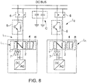
- the common bus DC BUS is recognized as well as the supply lines L1 and L2, here two in number for the sake of clarity, and the common mode decoupling and damping circuit comprising two capacitors C and the inductors Lh with the primary windings 1 and 2 and secondary 4 and the resistance R in parallel.
- the power system is completed by protection means.
- protection means comprise, for each line, a circuit breaker 5 with electronic components, here IGBT (for "Insulated Gate Bipolar Transistor", in English) controlled by a control circuit (not shown) from the value of the current flowing in the line provided by a suitable measurement sensor (not shown).
- IGBT Insulated Gate Bipolar Transistor
- the control circuit controls the opening of the power component.
- such a protection stage is particularly effective insofar as it is able to act very quickly to isolate a defective circuit portion.
- it may be insufficiently robust to the extent that it may itself be defective.
- the protection means comprise, for each line, an isolation means comprising an electromechanical or electromagnetic switch 6, for example an advantageously motorized switch, which may be longer to open but which presents improved insulation insofar as the opening of the circuit is carried out here mechanically.
- the protection means are completed by a non-return diode 7 preventing the flow of current from a converter or, in general, a defective charge to the common bus.
- step I With reference to the figure 9 when a short circuit appears on a line between the protection means 5 and the DC / AC converter, the DC / AC converter is stopped by opening its IGBT transistors (step I).
- phase II it causes the quick opening of the circuit breaker 5 to open the branch of the defective circuit and prevent the current of the short circuit flows to the DC bus and to the other loads.
- the anti-return diodes 7 prevent the flow of current from the converter of the defective line and that the capacitors of the other DC / AC converters are discharged in the defective power line.
- next phase III it causes the opening of the electromechanical switch 6 to mechanically isolate the defective circuit portion and safely allow the implementation of maintenance operations on this line.
Description
La présente invention concerne les systèmes d'alimentation de charges électriques destinés notamment, mais non exclusivement, à des applications sous-marines.The present invention relates to electric charge supply systems intended in particular, but not exclusively, for submarine applications.
Elle se rapporte plus particulièrement à un système d'alimentation de charges alimentées en parallèle à partir d'un bus commun d'alimentation en courant continu.It relates more particularly to a system for supplying loads powered in parallel from a common DC power supply bus.
Les charges alimentées peuvent être de diverses natures et être par exemple constituées par des moteurs à courant alternatif alimentés par des lignes d'alimentation raccordées en parallèle au bus continu par l'intermédiaire d'un convertisseur continu/alternatif.The feeds can be of various kinds and be constituted for example by AC motors powered by power lines connected in parallel to the DC bus via a DC / AC converter.
Le convertisseur constitue un onduleur qui peut par exemple être réalisé à partir de cellules de commutation qui peuvent être pilotées par modulation par largeur d'impulsions.The converter constitutes an inverter which can for example be made from switching cells which can be controlled by pulse width modulation.
Comme on le conçoit, en particulier pour des applications sous-marines, la longueur de la ligne d'alimentation du côté continu, s'étendant entre le bus continu et le convertisseur, et la longueur de la ligne d'alimentation côté alternatif, entre le convertisseur et la charge, peuvent être relativement importantes et varier de manière significative d'une ligne d'alimentation à une autre.As is conceivable, particularly for submarine applications, the length of the DC side feed line extending between the DC bus and the converter, and the length of the AC side feed line between the converter and the load, can be relatively large and vary significantly from one power line to another.
En outre, les charges, par exemple des moteurs électriques, peuvent présenter des puissances différentes.In addition, the loads, for example electric motors, may have different powers.
Pour ces raisons, l'impédance globale des lignes d'alimentation, y compris des charges, peut varier de manière significative.For these reasons, the overall impedance of power lines, including loads, can vary significantly.
Les charges électriques connectées aux lignes d'alimentation parallèles sont susceptibles de comporter des composants d'électronique de puissance qui peuvent générer des signaux homopolaires qui se propagent dans le bus d'alimentation continu et vers les autres lignes d'alimentation.The electrical loads connected to the parallel supply lines are likely to include power electronics components that can generate homopolar signals that propagate in the DC bus and to the other power lines.
Il peut notamment s'agir de convertisseurs dédiés à l'alimentation des charges qui peuvent générer des tensions homopolaires dans le système. De ces tensions résultent des courants homopolaires qui dépendent des impédances du circuit. Les signaux homopolaires peuvent en particulier se propager dans les lignes d'alimentation ayant des modèles d'impédance différents et engendrer des niveaux de tensions et courants excessifs qui peuvent être préjudiciables pour les systèmes d'isolation prévus dans les lignes d'alimentation et dans les charges.It can especially be converters dedicated to the supply of loads that can generate zero sequence voltages in the system. These voltages result in homopolar currents which depend on the impedances of the circuit. In particular, homopolar signals can propagate in power lines with different impedance patterns and cause excessive voltages and currents that can be detrimental to the isolation systems in power lines and loads.
On connaît, dans l'état de la technique, divers types de systèmes d'alimentation de charges capables notamment d'assurer une protection de portions d'un circuit d'alimentation en présence d'un défaut.In the state of the art, various types of charge supply systems are known, in particular capable of protecting portions of a supply circuit in the presence of a fault.
On pourra à cet égard se référer aux documents
On pourra également se référer au document
On connaît également, du document
Au vu de ce qui précède, l'invention a pour but de proposer un système d'alimentation d'un ensemble de charges raccordées en parallèle capable d'éviter la circulation de perturbations apparaissant dans une ligne d'alimentation de l'une des charges et d'éviter que ces perturbations ne circulent dans les autres charges.In view of the foregoing, the object of the invention is to propose a system for supplying a set of charges connected in parallel capable of preventing the circulation of disturbances appearing. in a supply line of one of the loads and to prevent these disturbances from circulating in the other loads.
A cet effet, il est proposé un système d'alimentation d'un ensemble de charges selon la revendication 1. Dans un mode de réalisation, les moyens de découplage et d'amortissement comportent en outre au moins une capacité de raccordement à la masse du bus d'alimentation.For this purpose, it is proposed a supply system of a set of loads according to
Selon la configuration des moyens de découplage et amortissement, on obtient une réduction des contraintes d'isolement des composants sensibles (tels que les moteurs, par exemple) par découplage des lignes d'alimentation, ainsi qu'une réduction et un amortissement des courants homopolaires circulant dans les lignes.Depending on the configuration of the decoupling and damping means, a reduction of the isolation stresses of the sensitive components (such as the motors, for example) by decoupling the supply lines, as well as a reduction and amortization of the homopolar currents circulating in the lines.
Avantageusement, une résistance est branchée en parallèle sur l'inductance.Advantageously, a resistor is connected in parallel to the inductor.
Selon une autre caractéristique de l'invention, le système d'alimentation comporte en outre des moyens de protection agissant en cas de défaut sur une portion du système d'alimentation.According to another characteristic of the invention, the supply system further comprises protection means acting in the event of a fault on a portion of the supply system.
Dans un mode de réalisation, les moyens de protection comprennent un ensemble de diodes anti-retour disposées sur les lignes d'alimentation de manière à interdire une circulation du courant vers le bus d'alimentation.In one embodiment, the protection means comprise a set of non-return diodes arranged on the supply lines so as to prevent a flow of current to the power supply bus.
Les moyens de protection comportent également, de préférence, un disjoncteur à composants électroniques de commutation piloté par un système de commande à partir de la valeur du courant circulant dans ladite portion du système d'alimentation.The protection means also preferably comprise a circuit breaker with electronic switching components controlled by a control system from the value of the current flowing in said portion of the supply system.
On peut en outre prévoir un commutateur électromécanique activé en cas de défaut sur ladite portion du système de protection.An electromechanical switch can also be activated in the event of a fault on said portion of the protection system.
Par ailleurs, selon encore une autre caractéristique du système d'alimentation, les lignes d'alimentation comprennent un convertisseur courant continu/courant alternatif alimentant lesdites charges.Furthermore, according to yet another characteristic of the power system, the power supply lines comprise a DC / AC converter supplying said loads.
D'autres buts, caractéristiques et avantages de l'invention apparaîtront à la lecture de la description suivante, donnée uniquement à titre d'exemple non limitatif, et faite en référence aux dessins annexés sur lesquels :
- la
figure 1 illustre schématiquement un système d'alimentation de charges placées en parallèle ; - les
figures 2 et 3 sont des schémas équivalents homopolaires d'un système d'alimentation comprenant deux lignes d'alimentation en parallèle ; - la
figure 4 est un schéma illustrant le principe de réalisation d'un premier mode de réalisation d'un système d'alimentation conforme à l'invention ; - la
figure 5 est un schéma illustrant le principe d'un système d'alimentation selon un deuxième mode de réalisation selon l'invention ; - la
figure 6 est un schéma montrant le principe de réalisation d'un système d'alimentation selon un mode de réalisation préféré ; - les
figures 7a et 7b d'une part, et 7c et 7d d'autre part, représentent le circuit électrique et une vue schématique d'un mode de réalisation de l'inductance entrant dans la constitution du système d'alimentation desfigures 5 et 6 , respectivement en mode différentiel et en mode commun; - la
figure 8 illustre de manière détaillée un mode de réalisation préféré d'un système d'alimentation conforme à l'invention ; et - les
figures 9 et 10 sont des schémas illustrant le fonctionnement des deuxièmes moyens de protection d'un système selon l'invention.
- the
figure 1 schematically illustrates a load feed system placed in parallel; - the
Figures 2 and 3 are equivalent homopolar diagrams of a power system that includes two parallel power lines; - the
figure 4 is a diagram illustrating the principle of making a first embodiment of a power system according to the invention; - the
figure 5 is a diagram illustrating the principle of a power system according to a second embodiment according to the invention; - the
figure 6 is a diagram showing the embodiment of a power system according to a preferred embodiment; - the
Figures 7a and 7b on the one hand, and 7c and 7d on the other hand, represent the electric circuit and a schematic view of an embodiment of the inductance used in the constitution of the power supply system.Figures 5 and 6 , respectively in differential mode and in common mode; - the
figure 8 illustrates in detail a preferred embodiment of a feed system according to the invention; and - the
Figures 9 and 10 are diagrams illustrating the operation of the second means of protection of a system according to the invention.
Sur la
Comme on le voit, le système d'alimentation comporte un bus d'alimentation DC BUS auquel sont raccordées un ensemble de lignes d'alimentation L1, ..., Ln assurant l'alimentation des charges proprement dites.As can be seen, the power supply system comprises a DC BUS supply bus to which are connected a set of supply lines L1,..., Ln ensuring the supply of the loads themselves.
Dans l'exemple de réalisation envisagé, le bus est un bus d'alimentation à courant continu et à moyenne tension MVDC.In the exemplary embodiment envisaged, the bus is a DCDC and MVDC power supply bus.
Les charges alimentées sont ici constituées par des moteurs M à courant alternatif.The feeds are here constituted by AC motors.
On notera cependant que l'on ne sort pas du cadre de l'invention lorsqu'il s'agit d'assurer l'alimentation de tout autre type de charges raccordées en parallèle à un bus d'alimentation continue.Note however that it is not beyond the scope of the invention when it comes to supplying any other type of charges connected in parallel to a DC power bus.
Comme on le voit, les moteurs sont alimentés par les lignes d'alimentation par l'intermédiaire de convertisseurs DC/AC.As can be seen, the motors are powered by the power supply lines via DC / AC converters.
Comme indiqué précédemment, les charges, et en particulier les convertisseurs, sont susceptibles de générer des tensions ou des courants homopolaires qui peuvent provoquer l'apparition de hautes tensions qui peuvent être nuisibles pour les moyens d'isolation des lignes d'alimentation, des convertisseurs et des moteurs.As indicated above, the loads, and in particular the converters, are capable of generating voltages or homopolar currents which can cause the appearance of high voltages which may be harmful for the means of isolating the supply lines, the converters and engines.
On a représenté sur la
Sur ce schéma, Zb1 et Zb2 représentent respectivement les impédances équivalentes entre le système (convertisseur, charge y compris les portions alternatives des lignes d'alimentation et les impédances des moteurs) et la terre, et Za représente l'impédance équivalente entre le bus et la terre, côté continu. Vzs1 et Vzs2 représentent la tension homopolaire générée par les convertisseurs des deux lignes d'alimentation et Vb1 et Vb2 représentent la tension aux bornes des impédances Zb1 et Zb2.In this diagram, Z b1 and Z b2 respectively represent the equivalent impedances between the system (converter, load including the alternating portions of the supply lines and the impedances of the motors) and the earth, and Z a represents the equivalent impedance between the bus and the earth, continuous side. Vzs 1 and Vzs 2 represent the homopolar voltage generated by the converters of the two supply lines and V b1 and V b2 represent the voltage across the impedances Z b1 and Z b2 .
Comme on le conçoit, le circuit équivalent est très dépendant de la valeur de ses paramètres. Par exemple, si Zb2 est négligeable devant Za et Zb1, le circuit équivalent devient celui de la
On a alors : ![]()
![]()
Ainsi, la tension au niveau de l'isolation du moteur peut atteindre la somme des tensions homopolaires Vzs1 et Vzs2.Thus, the voltage at the insulation of the motor can reach the sum of the zero sequence voltages Vzs1 and Vzs2.
Pour pallier cet inconvénient, comme illustré à la
Il est également possible, comme visible sur la
Ainsi, afin d'éviter les interactions entre les lignes d'alimentation tout en réduisant les signaux homopolaires, en référence à la
On a représenté sur les
L'inductance est réalisée à partir de deux enroulements 1 et 2 bobinés ou alimentés en sens inverse autour d'un noyau 3.The inductance is made from two
Comme illustré par les flèches FI et F2, qui illustrent les courants IP+ et Ip- qui circulent dans le bobinage de l'inductance, en mode commun, les courants IP+ et Ip- circulent dans le même sens dans les deux enroulements tandis qu'en mode différentiel, les courants circulent en sens inverse. En mode différentiel, les deux flux magnétiques créés par les enroulements 1 et 2 ont des signes opposés et s'annulent (flèches F3 et F4). En mode commun, les flux magnétiques sont générés dans la même direction et s'additionnent de sorte qu'une impédance élevée est obtenue.As illustrated by the arrows FI and F2, which illustrate the currents IP + and Ip- which circulate in the winding of the inductor, in In common mode, the currents IP + and Ip- flow in the same direction in the two windings while in differential mode, the currents flow in the opposite direction. In differential mode, the two magnetic fluxes created by the
Il est possible, mais non obligatoire, d'ajouter une résistance d'amortissement en parallèle d'une bobine 1 ou 2 de l'inductance homopolaire ou en parallèle de la bobine 1 et de la bobine 2.It is possible, but not obligatory, to add a damping resistor in parallel with a
Comme représenté, il est également possible d'ajouter, de manière optionnelle, une résistance d'amortissement Rh en parallèle d'une bobine d'inductance homopolaire 4.As shown, it is also possible to add, optionally, a damping resistor Rh in parallel with a
On a représenté sur la
Sur cette figure, on reconnaît le bus commun DC BUS ainsi que les lignes d'alimentation L1 et L2, ici au nombre de deux par souci de clarté, et le circuit de découplage et amortissement en mode commun comprenant deux capacités C et les inductances Lh avec les enroulements primaire 1 et 2 et secondaire 4 et la résistance R en parallèle.In this figure, the common bus DC BUS is recognized as well as the supply lines L1 and L2, here two in number for the sake of clarity, and the common mode decoupling and damping circuit comprising two capacitors C and the inductors Lh with the
Dans le but d'éviter qu'un défaut, tel qu'un court-circuit, présent dans une charge de l'une des lignes ne se propage sur le bus commun, le système d'alimentation est complété par des moyens de protection.In order to prevent a fault, such as a short circuit, present in a load of one of the lines from spreading on the common bus, the power system is completed by protection means.
Ces moyens de protection comportent, pour chaque ligne, un disjoncteur 5 à composants électroniques, ici à IGBT (pour « Insulated Gâte Bipolar Transistor », en anglais) piloté par un circuit de commande (non représenté) à partir de la valeur du courant circulant dans la ligne fournie par un capteur de mesure approprié (non représenté).These protection means comprise, for each line, a
Dès que le courant dépasse une valeur de seuil prédéterminée, le circuit de commande pilote l'ouverture du composant de puissance.As soon as the current exceeds a predetermined threshold value, the control circuit controls the opening of the power component.
Comme on le conçoit, un tel étage de protection est particulièrement efficace dans la mesure où il est capable d'agir très rapidement pour isoler une portion de circuit défectueuse. Il peut toutefois présenter une robustesse insuffisante dans la mesure où il peut lui-même faire l'objet de défauts.As conceived, such a protection stage is particularly effective insofar as it is able to act very quickly to isolate a defective circuit portion. However, it may be insufficiently robust to the extent that it may itself be defective.
Pour améliorer la robustesse de la protection, les moyens de protection comportent, pour chaque ligne, un moyen d'isolement comprenant un commutateur électromécanique ou électromagnétique 6, par exemple un interrupteur avantageusement motorisé, qui peut être plus long à s'ouvrir mais qui présente un isolement amélioré dans la mesure où l'ouverture du circuit s'effectue ici mécaniquement.To improve the robustness of the protection, the protection means comprise, for each line, an isolation means comprising an electromechanical or
On voit enfin sur la
On va maintenant décrire le fonctionnement du circuit qui vient d'être décrit en présence d'un défaut sur une ligne.We will now describe the operation of the circuit that has just been described in the presence of a defect on a line.
En référence à la
Lors de la phase II, on provoque l'ouverture rapide du disjoncteur 5 pour ouvrir la branche du circuit défectueuse et éviter que le courant du court-circuit circule vers le bus DC puis vers les autres charges.During phase II, it causes the quick opening of the
Les diodes anti-retour 7 empêchent la circulation d'un courant provenant du convertisseur de la ligne défectueuse et que les condensateurs des autres convertisseurs DC/AC ne se déchargent dans la ligne d'alimentation défectueuse.The
Lors de la phase III suivante, on provoque l'ouverture du commutateur électromécanique 6 afin d'isoler mécaniquement la portion de circuit défectueuse et permettre en sécurité la mise en oeuvre d'opérations de maintenance sur cette ligne.During the next phase III, it causes the opening of the
Claims (7)
- System for supplying power to a set of loads, comprising a DC power supply bus (DC BUS) and a set of power supply lines that are connected in parallel to the power supply bus and provide said loads with a supply of power, characterized in that the system comprises decoupling and damping means (Lh, C) that are suitable for decreasing the homopolar signals flowing through the power supply system when supplying power to the loads, the decoupling and damping means comprising, on each power supply line, one or more inductors (Lh) that are positioned in series with a converter, on the DC current side, and one or more capacitors (C) linking the DC bus to ground.
- Power supply system according to Claim 1, comprising a resistor (R) that is connected in parallel to the inductor.
- Power supply system according to either of Claims 1 and 2, further comprising protection means (5, 6, 7) acting, in the event of a fault, on a portion of the power supply system.
- Power supply system according to Claim 3, wherein the protection means comprise a set of non-return diodes (7) that are positioned on the power supply lines so as to prevent a current flow towards the power supply bus.
- Power supply system according to either of Claims 3 and 4, wherein the protection means include a circuit breaker (5) having switching electronic components that is driven by a control system on the basis of the value of the current flowing through said portion of the power supply system.
- System according to any one of Claims 3 to 5, wherein the protection means include an electromechanical switch (6) that is activated in the event of a fault on said portion of the protection system.
- System according to any one of Claims 1 to 6, wherein the power supply lines comprise a DC-to-AC converter supplying power to said loads.
Priority Applications (3)
| Application Number | Priority Date | Filing Date | Title |
|---|---|---|---|
| EP15306514.9A EP3148032B1 (en) | 2015-09-28 | 2015-09-28 | Power supply system of a set of loads connected in parallel to a dc power bus |
| US15/762,566 US10972000B2 (en) | 2015-09-28 | 2016-09-26 | Supply system to a set of loads connected in parallel to a direct current supply bus |
| PCT/GB2016/052983 WO2017055817A1 (en) | 2015-09-28 | 2016-09-26 | Supply system for a plurality of loads connected in parallel to a direct current supply bus |
Applications Claiming Priority (1)
| Application Number | Priority Date | Filing Date | Title |
|---|---|---|---|
| EP15306514.9A EP3148032B1 (en) | 2015-09-28 | 2015-09-28 | Power supply system of a set of loads connected in parallel to a dc power bus |
Publications (2)
| Publication Number | Publication Date |
|---|---|
| EP3148032A1 EP3148032A1 (en) | 2017-03-29 |
| EP3148032B1 true EP3148032B1 (en) | 2018-03-28 |
Family
ID=54291215
Family Applications (1)
| Application Number | Title | Priority Date | Filing Date |
|---|---|---|---|
| EP15306514.9A Active EP3148032B1 (en) | 2015-09-28 | 2015-09-28 | Power supply system of a set of loads connected in parallel to a dc power bus |
Country Status (3)
| Country | Link |
|---|---|
| US (1) | US10972000B2 (en) |
| EP (1) | EP3148032B1 (en) |
| WO (1) | WO2017055817A1 (en) |
Families Citing this family (3)
| Publication number | Priority date | Publication date | Assignee | Title |
|---|---|---|---|---|
| CN107508262B (en) * | 2017-08-22 | 2019-05-28 | 云南电网有限责任公司电力科学研究院 | A kind of pole protection voltage acquisition circuit and inverter zero sequence over-voltage protection method |
| US20190368315A1 (en) * | 2018-06-05 | 2019-12-05 | Saudi Arabian Oil Company | Power supply for offshore equipment and operations |
| CN113067375A (en) * | 2021-03-26 | 2021-07-02 | 南华大学 | Generalized comprehensive load modeling method and simulation system for alternating current-direct current hybrid power distribution network |
Family Cites Families (12)
| Publication number | Priority date | Publication date | Assignee | Title |
|---|---|---|---|---|
| US6469485B2 (en) * | 2000-07-07 | 2002-10-22 | Honeywell International Inc. | Active filter and method for suppressing current harmonics |
| US8446037B2 (en) * | 2009-12-04 | 2013-05-21 | Kevin R. Williams | Energy storage system for peak-shaving of drilling rig power usage |
| FR2963509B1 (en) | 2010-07-29 | 2013-07-26 | Converteam Technology Ltd | SYSTEM FOR SUPPLYING AN ALTERNATING CURRENT CHARGE FROM AN ALTERNATIVE NETWORK WITHOUT A TRANSFORMER BETWEEN THE NETWORK AND THE POWER SUPPLY SYSTEM, AND A DRIVE CHAIN COMPRISING SUCH A SYSTEM |
| DE112011104777T5 (en) * | 2011-03-31 | 2013-10-31 | Mitsubishi Electric Corporation | AC motor driving device |
| US9083233B2 (en) * | 2011-10-05 | 2015-07-14 | General Electric Company | Dynamic break and distortion filter |
| DK2634885T3 (en) | 2012-02-29 | 2015-11-23 | Abb Technology Ltd | DC power system with system protection features |
| US9789973B2 (en) * | 2012-04-05 | 2017-10-17 | Hamilton Sundstrand Corporation | Power interruption bridge circuit |
| WO2014037583A2 (en) | 2012-09-10 | 2014-03-13 | Abb Technology Ag | Power distribution system for autonomous facilities |
| US9270119B2 (en) | 2013-05-24 | 2016-02-23 | Eaton Corporation | High voltage direct current transmission and distribution system |
| US9627862B2 (en) | 2013-12-26 | 2017-04-18 | General Electric Company | Methods and systems for subsea direct current power distribution |
| US10184452B2 (en) * | 2014-09-16 | 2019-01-22 | Mitsubishi Electric Corporation | Wind power generation system and DC power transmission system |
| US9621101B2 (en) * | 2014-12-09 | 2017-04-11 | Johnson Controls Technology Company | Electromagnetic compatibility filter |
-
2015
- 2015-09-28 EP EP15306514.9A patent/EP3148032B1/en active Active
-
2016
- 2016-09-26 US US15/762,566 patent/US10972000B2/en active Active
- 2016-09-26 WO PCT/GB2016/052983 patent/WO2017055817A1/en active Application Filing
Non-Patent Citations (1)
| Title |
|---|
| None * |
Also Published As
| Publication number | Publication date |
|---|---|
| EP3148032A1 (en) | 2017-03-29 |
| US20180278155A1 (en) | 2018-09-27 |
| WO2017055817A1 (en) | 2017-04-06 |
| US10972000B2 (en) | 2021-04-06 |
Similar Documents
| Publication | Publication Date | Title |
|---|---|---|
| EP2267880B1 (en) | power converter using a rectifier with normallly closed transistors | |
| EP3105845B1 (en) | Dc voltage supply system configured to precharge a smoothing capacitor before supplying a load | |
| EP3148032B1 (en) | Power supply system of a set of loads connected in parallel to a dc power bus | |
| EP1746700B1 (en) | Power supply apparatus of a speed regulator | |
| EP2008357B1 (en) | Switching circuit for the series implementation of igbt transistors | |
| EP2677645B1 (en) | System for powering a load, comprising a converter connected to a network and a transformer connected in parallel to the converter to limit the zero sequence current, and drive chain comprising such a system | |
| EP3208909B1 (en) | Mixed ac-dc electrical power distribution system for supplying variable-frequency loads and fixed-frequency loads | |
| EP3255774A1 (en) | System for converting electric energy supplied by a network and conversion method implemented by means of such a conversion system | |
| EP2413485B1 (en) | System for supplying an alternating current charge from an AC grid with no transformer between the grid and the supply system, and power transmission chain including such a system | |
| EP2562903A2 (en) | Reactive power compensator comprising N inverters in parallel, N banks of capacitor(s) and a means for connecting the banks via passive electrical components | |
| FR2921211A1 (en) | Polyphase alternating current active rectifier system for converting polyphase alternating current to direct current, has neutral direct current level between positive and negative levels that are on positive and negative lines | |
| EP2346154A1 (en) | System for powering an element among a rotor and a stator of an electric machine, and method for controlling such a system | |
| FR2940863A1 (en) | POWER SUPPLY OF AN AIRCRAFT | |
| EP3657677A1 (en) | Circuit for supplying circuits for controlling switches | |
| WO2007074268A2 (en) | Rotating electrical machine with decoupled phases | |
| EP2638632B1 (en) | Power supply circuit for an aircraft including an asynchronous machine | |
| EP3270515B1 (en) | High-voltage high-speed switch | |
| WO2012084389A2 (en) | Power converter equipped at the output with a filtering device | |
| EP4078755B1 (en) | Dc/dc voltage converter provided with a circuit-breaker device | |
| EP3799671B1 (en) | System comprising a power flow control device used to control the distribution of currents in a grid network and means for protecting said device | |
| EP2293422B1 (en) | Converter of one direct current to another direct current with control signal interleaving, and power supply system including such a converter | |
| EP3139485B1 (en) | Soft starting system for an electrical motor | |
| FR3015146A1 (en) | SYSTEMS AND METHODS FOR PROVIDING AUXILIARY CURRENT SUPPLY IN HIGH VOLTAGE CONVERTERS | |
| FR3091423A1 (en) | PROTECTION AGAINST OVERVOLTAGES OF A VARIABLE SPEED AND CONSTANT FREQUENCY ELECTRIC POWER GENERATION SYSTEM | |
| WO2015055951A1 (en) | Device for protecting against short-circuits upstream of a power module |
Legal Events
| Date | Code | Title | Description |
|---|---|---|---|
| PUAI | Public reference made under article 153(3) epc to a published international application that has entered the european phase |
Free format text: ORIGINAL CODE: 0009012 |
|
| AK | Designated contracting states |
Kind code of ref document: A1 Designated state(s): AL AT BE BG CH CY CZ DE DK EE ES FI FR GB GR HR HU IE IS IT LI LT LU LV MC MK MT NL NO PL PT RO RS SE SI SK SM TR |
|
| AX | Request for extension of the european patent |
Extension state: BA ME |
|
| 17P | Request for examination filed |
Effective date: 20170901 |
|
| RIC1 | Information provided on ipc code assigned before grant |
Ipc: H02J 3/36 20060101ALI20170919BHEP Ipc: H02J 1/10 20060101AFI20170919BHEP Ipc: H02H 7/26 20060101ALI20170919BHEP |
|
| GRAP | Despatch of communication of intention to grant a patent |
Free format text: ORIGINAL CODE: EPIDOSNIGR1 |
|
| INTG | Intention to grant announced |
Effective date: 20171115 |
|
| GRAS | Grant fee paid |
Free format text: ORIGINAL CODE: EPIDOSNIGR3 |
|
| GRAA | (expected) grant |
Free format text: ORIGINAL CODE: 0009210 |
|
| AK | Designated contracting states |
Kind code of ref document: B1 Designated state(s): AL AT BE BG CH CY CZ DE DK EE ES FI FR GB GR HR HU IE IS IT LI LT LU LV MC MK MT NL NO PL PT RO RS SE SI SK SM TR |
|
| REG | Reference to a national code |
Ref country code: GB Ref legal event code: FG4D Free format text: NOT ENGLISH |
|
| REG | Reference to a national code |
Ref country code: CH Ref legal event code: EP |
|
| REG | Reference to a national code |
Ref country code: AT Ref legal event code: REF Ref document number: 984229 Country of ref document: AT Kind code of ref document: T Effective date: 20180415 |
|
| REG | Reference to a national code |
Ref country code: IE Ref legal event code: FG4D Free format text: LANGUAGE OF EP DOCUMENT: FRENCH |
|
| REG | Reference to a national code |
Ref country code: DE Ref legal event code: R096 Ref document number: 602015009292 Country of ref document: DE |
|
| PG25 | Lapsed in a contracting state [announced via postgrant information from national office to epo] |
Ref country code: LT Free format text: LAPSE BECAUSE OF FAILURE TO SUBMIT A TRANSLATION OF THE DESCRIPTION OR TO PAY THE FEE WITHIN THE PRESCRIBED TIME-LIMIT Effective date: 20180328 Ref country code: HR Free format text: LAPSE BECAUSE OF FAILURE TO SUBMIT A TRANSLATION OF THE DESCRIPTION OR TO PAY THE FEE WITHIN THE PRESCRIBED TIME-LIMIT Effective date: 20180328 Ref country code: NO Free format text: LAPSE BECAUSE OF FAILURE TO SUBMIT A TRANSLATION OF THE DESCRIPTION OR TO PAY THE FEE WITHIN THE PRESCRIBED TIME-LIMIT Effective date: 20180628 Ref country code: FI Free format text: LAPSE BECAUSE OF FAILURE TO SUBMIT A TRANSLATION OF THE DESCRIPTION OR TO PAY THE FEE WITHIN THE PRESCRIBED TIME-LIMIT Effective date: 20180328 |
|
| REG | Reference to a national code |
Ref country code: NL Ref legal event code: MP Effective date: 20180328 |
|
| REG | Reference to a national code |
Ref country code: LT Ref legal event code: MG4D |
|
| REG | Reference to a national code |
Ref country code: FR Ref legal event code: PLFP Year of fee payment: 4 |
|
| PG25 | Lapsed in a contracting state [announced via postgrant information from national office to epo] |
Ref country code: BG Free format text: LAPSE BECAUSE OF FAILURE TO SUBMIT A TRANSLATION OF THE DESCRIPTION OR TO PAY THE FEE WITHIN THE PRESCRIBED TIME-LIMIT Effective date: 20180628 Ref country code: GR Free format text: LAPSE BECAUSE OF FAILURE TO SUBMIT A TRANSLATION OF THE DESCRIPTION OR TO PAY THE FEE WITHIN THE PRESCRIBED TIME-LIMIT Effective date: 20180629 Ref country code: SE Free format text: LAPSE BECAUSE OF FAILURE TO SUBMIT A TRANSLATION OF THE DESCRIPTION OR TO PAY THE FEE WITHIN THE PRESCRIBED TIME-LIMIT Effective date: 20180328 Ref country code: LV Free format text: LAPSE BECAUSE OF FAILURE TO SUBMIT A TRANSLATION OF THE DESCRIPTION OR TO PAY THE FEE WITHIN THE PRESCRIBED TIME-LIMIT Effective date: 20180328 Ref country code: RS Free format text: LAPSE BECAUSE OF FAILURE TO SUBMIT A TRANSLATION OF THE DESCRIPTION OR TO PAY THE FEE WITHIN THE PRESCRIBED TIME-LIMIT Effective date: 20180328 |
|
| PG25 | Lapsed in a contracting state [announced via postgrant information from national office to epo] |
Ref country code: MT Free format text: LAPSE BECAUSE OF FAILURE TO SUBMIT A TRANSLATION OF THE DESCRIPTION OR TO PAY THE FEE WITHIN THE PRESCRIBED TIME-LIMIT Effective date: 20180328 |
|
| PG25 | Lapsed in a contracting state [announced via postgrant information from national office to epo] |
Ref country code: NL Free format text: LAPSE BECAUSE OF FAILURE TO SUBMIT A TRANSLATION OF THE DESCRIPTION OR TO PAY THE FEE WITHIN THE PRESCRIBED TIME-LIMIT Effective date: 20180328 Ref country code: PL Free format text: LAPSE BECAUSE OF FAILURE TO SUBMIT A TRANSLATION OF THE DESCRIPTION OR TO PAY THE FEE WITHIN THE PRESCRIBED TIME-LIMIT Effective date: 20180328 Ref country code: AL Free format text: LAPSE BECAUSE OF FAILURE TO SUBMIT A TRANSLATION OF THE DESCRIPTION OR TO PAY THE FEE WITHIN THE PRESCRIBED TIME-LIMIT Effective date: 20180328 Ref country code: ES Free format text: LAPSE BECAUSE OF FAILURE TO SUBMIT A TRANSLATION OF THE DESCRIPTION OR TO PAY THE FEE WITHIN THE PRESCRIBED TIME-LIMIT Effective date: 20180328 Ref country code: RO Free format text: LAPSE BECAUSE OF FAILURE TO SUBMIT A TRANSLATION OF THE DESCRIPTION OR TO PAY THE FEE WITHIN THE PRESCRIBED TIME-LIMIT Effective date: 20180328 Ref country code: IT Free format text: LAPSE BECAUSE OF FAILURE TO SUBMIT A TRANSLATION OF THE DESCRIPTION OR TO PAY THE FEE WITHIN THE PRESCRIBED TIME-LIMIT Effective date: 20180328 Ref country code: EE Free format text: LAPSE BECAUSE OF FAILURE TO SUBMIT A TRANSLATION OF THE DESCRIPTION OR TO PAY THE FEE WITHIN THE PRESCRIBED TIME-LIMIT Effective date: 20180328 |
|
| PG25 | Lapsed in a contracting state [announced via postgrant information from national office to epo] |
Ref country code: CZ Free format text: LAPSE BECAUSE OF FAILURE TO SUBMIT A TRANSLATION OF THE DESCRIPTION OR TO PAY THE FEE WITHIN THE PRESCRIBED TIME-LIMIT Effective date: 20180328 Ref country code: SM Free format text: LAPSE BECAUSE OF FAILURE TO SUBMIT A TRANSLATION OF THE DESCRIPTION OR TO PAY THE FEE WITHIN THE PRESCRIBED TIME-LIMIT Effective date: 20180328 Ref country code: SK Free format text: LAPSE BECAUSE OF FAILURE TO SUBMIT A TRANSLATION OF THE DESCRIPTION OR TO PAY THE FEE WITHIN THE PRESCRIBED TIME-LIMIT Effective date: 20180328 |
|
| REG | Reference to a national code |
Ref country code: AT Ref legal event code: MK05 Ref document number: 984229 Country of ref document: AT Kind code of ref document: T Effective date: 20180328 |
|
| PG25 | Lapsed in a contracting state [announced via postgrant information from national office to epo] |
Ref country code: PT Free format text: LAPSE BECAUSE OF FAILURE TO SUBMIT A TRANSLATION OF THE DESCRIPTION OR TO PAY THE FEE WITHIN THE PRESCRIBED TIME-LIMIT Effective date: 20180730 |
|
| REG | Reference to a national code |
Ref country code: DE Ref legal event code: R097 Ref document number: 602015009292 Country of ref document: DE |
|
| PG25 | Lapsed in a contracting state [announced via postgrant information from national office to epo] |
Ref country code: AT Free format text: LAPSE BECAUSE OF FAILURE TO SUBMIT A TRANSLATION OF THE DESCRIPTION OR TO PAY THE FEE WITHIN THE PRESCRIBED TIME-LIMIT Effective date: 20180328 Ref country code: DK Free format text: LAPSE BECAUSE OF FAILURE TO SUBMIT A TRANSLATION OF THE DESCRIPTION OR TO PAY THE FEE WITHIN THE PRESCRIBED TIME-LIMIT Effective date: 20180328 |
|
| PLBE | No opposition filed within time limit |
Free format text: ORIGINAL CODE: 0009261 |
|
| STAA | Information on the status of an ep patent application or granted ep patent |
Free format text: STATUS: NO OPPOSITION FILED WITHIN TIME LIMIT |
|
| 26N | No opposition filed |
Effective date: 20190103 |
|
| REG | Reference to a national code |
Ref country code: DE Ref legal event code: R119 Ref document number: 602015009292 Country of ref document: DE |
|
| PG25 | Lapsed in a contracting state [announced via postgrant information from national office to epo] |
Ref country code: MC Free format text: LAPSE BECAUSE OF FAILURE TO SUBMIT A TRANSLATION OF THE DESCRIPTION OR TO PAY THE FEE WITHIN THE PRESCRIBED TIME-LIMIT Effective date: 20180328 |
|
| REG | Reference to a national code |
Ref country code: CH Ref legal event code: PL |
|
| PG25 | Lapsed in a contracting state [announced via postgrant information from national office to epo] |
Ref country code: SI Free format text: LAPSE BECAUSE OF FAILURE TO SUBMIT A TRANSLATION OF THE DESCRIPTION OR TO PAY THE FEE WITHIN THE PRESCRIBED TIME-LIMIT Effective date: 20180328 |
|
| REG | Reference to a national code |
Ref country code: BE Ref legal event code: MM Effective date: 20180930 |
|
| REG | Reference to a national code |
Ref country code: IE Ref legal event code: MM4A |
|
| PG25 | Lapsed in a contracting state [announced via postgrant information from national office to epo] |
Ref country code: LU Free format text: LAPSE BECAUSE OF NON-PAYMENT OF DUE FEES Effective date: 20180928 |
|
| PG25 | Lapsed in a contracting state [announced via postgrant information from national office to epo] |
Ref country code: IE Free format text: LAPSE BECAUSE OF NON-PAYMENT OF DUE FEES Effective date: 20180928 Ref country code: DE Free format text: LAPSE BECAUSE OF NON-PAYMENT OF DUE FEES Effective date: 20190402 |
|
| PG25 | Lapsed in a contracting state [announced via postgrant information from national office to epo] |
Ref country code: LI Free format text: LAPSE BECAUSE OF NON-PAYMENT OF DUE FEES Effective date: 20180930 Ref country code: CH Free format text: LAPSE BECAUSE OF NON-PAYMENT OF DUE FEES Effective date: 20180930 Ref country code: BE Free format text: LAPSE BECAUSE OF NON-PAYMENT OF DUE FEES Effective date: 20180930 |
|
| PG25 | Lapsed in a contracting state [announced via postgrant information from national office to epo] |
Ref country code: TR Free format text: LAPSE BECAUSE OF FAILURE TO SUBMIT A TRANSLATION OF THE DESCRIPTION OR TO PAY THE FEE WITHIN THE PRESCRIBED TIME-LIMIT Effective date: 20180328 |
|
| PG25 | Lapsed in a contracting state [announced via postgrant information from national office to epo] |
Ref country code: CY Free format text: LAPSE BECAUSE OF FAILURE TO SUBMIT A TRANSLATION OF THE DESCRIPTION OR TO PAY THE FEE WITHIN THE PRESCRIBED TIME-LIMIT Effective date: 20180328 Ref country code: MK Free format text: LAPSE BECAUSE OF NON-PAYMENT OF DUE FEES Effective date: 20180328 Ref country code: HU Free format text: LAPSE BECAUSE OF FAILURE TO SUBMIT A TRANSLATION OF THE DESCRIPTION OR TO PAY THE FEE WITHIN THE PRESCRIBED TIME-LIMIT; INVALID AB INITIO Effective date: 20150928 |
|
| PG25 | Lapsed in a contracting state [announced via postgrant information from national office to epo] |
Ref country code: IS Free format text: LAPSE BECAUSE OF FAILURE TO SUBMIT A TRANSLATION OF THE DESCRIPTION OR TO PAY THE FEE WITHIN THE PRESCRIBED TIME-LIMIT Effective date: 20180728 |
|
| GBPC | Gb: european patent ceased through non-payment of renewal fee |
Effective date: 20190928 |
|
| PG25 | Lapsed in a contracting state [announced via postgrant information from national office to epo] |
Ref country code: GB Free format text: LAPSE BECAUSE OF NON-PAYMENT OF DUE FEES Effective date: 20190928 |
|
| PGFP | Annual fee paid to national office [announced via postgrant information from national office to epo] |
Ref country code: FR Payment date: 20230822 Year of fee payment: 9 |