EP4160798A1 - Battery module and battery pack having the same - Google Patents
Battery module and battery pack having the same Download PDFInfo
- Publication number
- EP4160798A1 EP4160798A1 EP22197094.0A EP22197094A EP4160798A1 EP 4160798 A1 EP4160798 A1 EP 4160798A1 EP 22197094 A EP22197094 A EP 22197094A EP 4160798 A1 EP4160798 A1 EP 4160798A1
- Authority
- EP
- European Patent Office
- Prior art keywords
- battery
- insulating cover
- venting
- disposed
- bus
- Prior art date
- Legal status (The legal status is an assumption and is not a legal conclusion. Google has not performed a legal analysis and makes no representation as to the accuracy of the status listed.)
- Pending
Links
- 238000013022 venting Methods 0.000 claims abstract description 82
- 238000005192 partition Methods 0.000 claims description 21
- 239000000463 material Substances 0.000 claims description 10
- 238000000638 solvent extraction Methods 0.000 claims description 3
- 238000009413 insulation Methods 0.000 description 3
- 230000002159 abnormal effect Effects 0.000 description 2
- 239000000428 dust Substances 0.000 description 2
- 229910000838 Al alloy Inorganic materials 0.000 description 1
- WHXSMMKQMYFTQS-UHFFFAOYSA-N Lithium Chemical compound [Li] WHXSMMKQMYFTQS-UHFFFAOYSA-N 0.000 description 1
- 229910000831 Steel Inorganic materials 0.000 description 1
- 229910052782 aluminium Inorganic materials 0.000 description 1
- XAGFODPZIPBFFR-UHFFFAOYSA-N aluminium Chemical compound [Al] XAGFODPZIPBFFR-UHFFFAOYSA-N 0.000 description 1
- 230000000712 assembly Effects 0.000 description 1
- 238000000429 assembly Methods 0.000 description 1
- 239000000919 ceramic Substances 0.000 description 1
- 238000004146 energy storage Methods 0.000 description 1
- 238000005516 engineering process Methods 0.000 description 1
- 239000000835 fiber Substances 0.000 description 1
- 239000011810 insulating material Substances 0.000 description 1
- 229910052744 lithium Inorganic materials 0.000 description 1
- 239000007769 metal material Substances 0.000 description 1
- 238000000034 method Methods 0.000 description 1
- 239000000203 mixture Substances 0.000 description 1
- 239000004033 plastic Substances 0.000 description 1
- 239000004417 polycarbonate Substances 0.000 description 1
- 229920000515 polycarbonate Polymers 0.000 description 1
- 238000007789 sealing Methods 0.000 description 1
- 239000010959 steel Substances 0.000 description 1
Images


Classifications
-
- H—ELECTRICITY
- H01—ELECTRIC ELEMENTS
- H01M—PROCESSES OR MEANS, e.g. BATTERIES, FOR THE DIRECT CONVERSION OF CHEMICAL ENERGY INTO ELECTRICAL ENERGY
- H01M50/00—Constructional details or processes of manufacture of the non-active parts of electrochemical cells other than fuel cells, e.g. hybrid cells
- H01M50/30—Arrangements for facilitating escape of gases
- H01M50/35—Gas exhaust passages comprising elongated, tortuous or labyrinth-shaped exhaust passages
- H01M50/358—External gas exhaust passages located on the battery cover or case
-
- H—ELECTRICITY
- H01—ELECTRIC ELEMENTS
- H01M—PROCESSES OR MEANS, e.g. BATTERIES, FOR THE DIRECT CONVERSION OF CHEMICAL ENERGY INTO ELECTRICAL ENERGY
- H01M50/00—Constructional details or processes of manufacture of the non-active parts of electrochemical cells other than fuel cells, e.g. hybrid cells
- H01M50/20—Mountings; Secondary casings or frames; Racks, modules or packs; Suspension devices; Shock absorbers; Transport or carrying devices; Holders
- H01M50/202—Casings or frames around the primary casing of a single cell or a single battery
-
- H—ELECTRICITY
- H01—ELECTRIC ELEMENTS
- H01M—PROCESSES OR MEANS, e.g. BATTERIES, FOR THE DIRECT CONVERSION OF CHEMICAL ENERGY INTO ELECTRICAL ENERGY
- H01M50/00—Constructional details or processes of manufacture of the non-active parts of electrochemical cells other than fuel cells, e.g. hybrid cells
- H01M50/20—Mountings; Secondary casings or frames; Racks, modules or packs; Suspension devices; Shock absorbers; Transport or carrying devices; Holders
- H01M50/204—Racks, modules or packs for multiple batteries or multiple cells
- H01M50/207—Racks, modules or packs for multiple batteries or multiple cells characterised by their shape
- H01M50/211—Racks, modules or packs for multiple batteries or multiple cells characterised by their shape adapted for pouch cells
-
- H—ELECTRICITY
- H01—ELECTRIC ELEMENTS
- H01M—PROCESSES OR MEANS, e.g. BATTERIES, FOR THE DIRECT CONVERSION OF CHEMICAL ENERGY INTO ELECTRICAL ENERGY
- H01M50/00—Constructional details or processes of manufacture of the non-active parts of electrochemical cells other than fuel cells, e.g. hybrid cells
- H01M50/20—Mountings; Secondary casings or frames; Racks, modules or packs; Suspension devices; Shock absorbers; Transport or carrying devices; Holders
- H01M50/233—Mountings; Secondary casings or frames; Racks, modules or packs; Suspension devices; Shock absorbers; Transport or carrying devices; Holders characterised by physical properties of casings or racks, e.g. dimensions
- H01M50/24—Mountings; Secondary casings or frames; Racks, modules or packs; Suspension devices; Shock absorbers; Transport or carrying devices; Holders characterised by physical properties of casings or racks, e.g. dimensions adapted for protecting batteries from their environment, e.g. from corrosion
-
- H—ELECTRICITY
- H01—ELECTRIC ELEMENTS
- H01M—PROCESSES OR MEANS, e.g. BATTERIES, FOR THE DIRECT CONVERSION OF CHEMICAL ENERGY INTO ELECTRICAL ENERGY
- H01M50/00—Constructional details or processes of manufacture of the non-active parts of electrochemical cells other than fuel cells, e.g. hybrid cells
- H01M50/20—Mountings; Secondary casings or frames; Racks, modules or packs; Suspension devices; Shock absorbers; Transport or carrying devices; Holders
- H01M50/271—Lids or covers for the racks or secondary casings
- H01M50/273—Lids or covers for the racks or secondary casings characterised by the material
- H01M50/282—Lids or covers for the racks or secondary casings characterised by the material having a layered structure
-
- H—ELECTRICITY
- H01—ELECTRIC ELEMENTS
- H01M—PROCESSES OR MEANS, e.g. BATTERIES, FOR THE DIRECT CONVERSION OF CHEMICAL ENERGY INTO ELECTRICAL ENERGY
- H01M50/00—Constructional details or processes of manufacture of the non-active parts of electrochemical cells other than fuel cells, e.g. hybrid cells
- H01M50/30—Arrangements for facilitating escape of gases
- H01M50/35—Gas exhaust passages comprising elongated, tortuous or labyrinth-shaped exhaust passages
- H01M50/367—Internal gas exhaust passages forming part of the battery cover or case; Double cover vent systems
-
- H—ELECTRICITY
- H01—ELECTRIC ELEMENTS
- H01M—PROCESSES OR MEANS, e.g. BATTERIES, FOR THE DIRECT CONVERSION OF CHEMICAL ENERGY INTO ELECTRICAL ENERGY
- H01M50/00—Constructional details or processes of manufacture of the non-active parts of electrochemical cells other than fuel cells, e.g. hybrid cells
- H01M50/50—Current conducting connections for cells or batteries
- H01M50/502—Interconnectors for connecting terminals of adjacent batteries; Interconnectors for connecting cells outside a battery casing
- H01M50/505—Interconnectors for connecting terminals of adjacent batteries; Interconnectors for connecting cells outside a battery casing comprising a single busbar
-
- H—ELECTRICITY
- H01—ELECTRIC ELEMENTS
- H01M—PROCESSES OR MEANS, e.g. BATTERIES, FOR THE DIRECT CONVERSION OF CHEMICAL ENERGY INTO ELECTRICAL ENERGY
- H01M50/00—Constructional details or processes of manufacture of the non-active parts of electrochemical cells other than fuel cells, e.g. hybrid cells
- H01M50/50—Current conducting connections for cells or batteries
- H01M50/572—Means for preventing undesired use or discharge
- H01M50/584—Means for preventing undesired use or discharge for preventing incorrect connections inside or outside the batteries
- H01M50/59—Means for preventing undesired use or discharge for preventing incorrect connections inside or outside the batteries characterised by the protection means
- H01M50/593—Spacers; Insulating plates
-
- Y—GENERAL TAGGING OF NEW TECHNOLOGICAL DEVELOPMENTS; GENERAL TAGGING OF CROSS-SECTIONAL TECHNOLOGIES SPANNING OVER SEVERAL SECTIONS OF THE IPC; TECHNICAL SUBJECTS COVERED BY FORMER USPC CROSS-REFERENCE ART COLLECTIONS [XRACs] AND DIGESTS
- Y02—TECHNOLOGIES OR APPLICATIONS FOR MITIGATION OR ADAPTATION AGAINST CLIMATE CHANGE
- Y02E—REDUCTION OF GREENHOUSE GAS [GHG] EMISSIONS, RELATED TO ENERGY GENERATION, TRANSMISSION OR DISTRIBUTION
- Y02E60/00—Enabling technologies; Technologies with a potential or indirect contribution to GHG emissions mitigation
- Y02E60/10—Energy storage using batteries
Definitions
- the present disclosure relates to technology related to a battery module and a battery pack.
- a lithium secondary battery In a lithium secondary battery, several unit cells may be bundled to form a battery pack, and the battery pack may be widely applied to a field requiring high energy, such as a vehicle battery or an energy storage system(ESS).
- ESS energy storage system
- An aspect of the present disclosure may minimize a phenomenon in which thermal runaway of a battery cell in a battery module leads to thermal runaway of another battery cell or another battery module.
- Another aspect of the present disclosure may provide a battery module having a structure for emitting flame, gas or dust occurring due to an abnormal action of a battery cell such as thermal runaway in a secondary battery in a desired direction.
- a battery module may include: a plurality of battery cells; and an insulating cover disposed on one side of the plurality of battery cells, the insulating cover comprising a venting guide configured to emit flame or gas occurring in one or more of the plurality of battery cells.
- the battery module may further include a bus-bar assembly including the at least one bus-bar electrically connected to at least one of the plurality of battery cells, wherein the insulating cover may be disposed to face the bus-bar assembly.
- the battery module may further include a heat-resistant sheet disposed between the insulating cover and the bus-bar assembly.
- the plurality of battery cells may include electrode leads output in a first direction, the insulating cover may face the plurality of battery cells in the first direction, and the venting guide may pass through the insulating cover in the first direction.
- the battery module may further include a cover sheet disposed on the venting guide to prevent foreign material from being introduced into the venting guide.
- the battery module may further include an outer cover disposed on one side of the insulating cover and including at least one venting hole communicating with the venting guide.
- a battery pack may include: a pack housing; and a plurality of battery modules accommodated in the pack housing, wherein the battery module may include: a plurality of battery cells; and an insulating cover disposed on one side of the plurality of battery cells, the insulating cover comprising a venting guide configured to emit flame or gas occurring in one or more of the plurality of battery cells.
- the pack housing may include a partition wall partitioning an inner space of the pack housing, the partition wall forming a first flow path guiding the flame or gas emitted from the venting guide.
- the pack housing may include a lower plate and a side frame disposed on an edge of the lower plate, and the side frame may form a second flow path communicating with the first flow path.
- the battery pack may further include a bus-bar assembly including the at least one bus-bar electrically connected to the at least one of the plurality of battery cells, wherein the insulating cover may face the bus-bar assembly.
- the battery pack may further include a heat-resistant sheet disposed between the insulating cover and the bus-bar assembly.
- the plurality of battery cells may include electrode leads output in a first direction, the insulating cover may face the plurality of battery cells in the first direction, and the venting guide may pass through the insulating cover in the first direction.
- the battery pack may further include a cover sheet disposed on the venting guide to prevent foreign material from being introduced into the venting guide.
- the battery pack may further include an outer cover disposed on the insulating cover and including at least one venting hole communicating with the venting guide.
- the partition wall may form two first flow paths spatially separated from each other by its structural shape.
- an X-direction, a Y-direction and a Z-direction may indicate a direction parallel to an X axis, a direction parallel to a Y axis, and a direction parallel to a Z axis, each shown in the drawings.
- the X-direction may be a concept including both a +X axis direction and a -X axis direction, which may be equally applied to the Y-direction and the Z-direction.
- a secondary battery may include a plurality of battery cells.
- the plurality of battery cells may be bundled to be an intermediate assembly such as a battery module, and the intermediate assemblies may be bundled to be a battery pack.
- the battery cell may have any of various shapes.
- the battery cell may have a pouch-shaped outer case surrounding an electrode assembly.
- the battery cell may have the electrode assembly accommodated in a cylindrical or prismatic outer case.
- the electrode assembly included in the battery cell may have a plurality of electrodes stacked on each other.
- the electrode may include a current collector and an electrode mixture applied to a surface of the current collector.
- a short circuit might occur between the electrodes due to an external impact or the like, which may lead to ignition of the battery cell. Flame or high-temperature gas emitted from the battery cell may cause serial ignition of another battery cell adjacent thereto.
- the battery pack includes the plurality of battery modules, fire occurring in one battery module may lead to fire in the entire battery pack.
- FIG. 1 is a perspective view of a battery module 100 according to an exemplary embodiment
- FIG. 2 is an exploded perspective view of the battery module 100 according to an exemplary embodiment
- FIG. 3 is a schematic cross-sectional view taken along line I-I' of the battery module 100 of FIG. 1
- FIG. 4 is a schematic cross-sectional view taken along line II-II' of the battery module 100 of FIG. 1 .
- the battery module 100 may include a plurality of battery cells 130 and an insulating cover 150 disposed on one side of the plurality of battery cells 130.
- the insulating cover 150 may be made of an insulating material such as plastic.
- the insulating cover 150 in an exemplary embodiment may include a venting guide 151.
- the venting guide 151 may provide a path for guiding and emitting flame or gas occurring in the battery cell 130 disposed on one side of the insulating cover 150 in a desired direction or position.
- the venting guide 151 may be open in the +X-direction, such that the flame or gas occurring in the battery cell 130 may be limited or wholly prevented from being emitted in the Y-direction or the Z-direction, and emitted in the +X-direction.
- the venting guide 151 may be open in a direction opposite to the battery cells 130.
- the insulating cover 150 may be disposed to face the battery cells 130 in the X-direction, and the venting guide 151 may be open in the X-direction. Accordingly, the flame or gas occurring in the battery cell 130 may be emitted through the venting guide 151 away from the battery cells 130.
- the battery cell 130 may include an electrode lead 131, and the venting guide 151 may be open in a direction in which the electrode lead 131 is output.
- the electrode lead 131 may be output in the X-direction
- the venting guide 151 may be open in the X-direction.
- an outer case surrounding an electrode assembly may have a relatively weak sealing strength at a portion where the electrode lead 131 is output.
- the gas or the flame might tend to be emitted in the direction in which the electrode lead 131 of the battery cell 130 is output.
- the venting guide 151 may be open in the direction in which the electrode lead 131 is output, and the flame or gas may thus be effectively emitted outward from the battery module 100, which may prevent or delay a serial ignition or thermal runaway of the battery cells 130.
- the battery module 100 may include a bus-bar assembly 140 connected to the battery cell 130.
- the battery module 100 may include the bus-bar assembly 140 disposed on one side of the battery cell 130.
- the bus-bar assembly 140 may include at least one bus-bar 141 connected to the battery cell 130.
- the bus-bar 141 may electrically connect two or more adjacent battery cells 130.
- the electrode lead 131 output from the battery cell 130 may be connected to the bus-bar 141.
- the bus-bar assembly 140 may include an insulation plate 142, and the bus-bar 141 may be disposed on the insulation plate 142.
- the bus-bar assembly 140 and the insulating cover 150 may be sequentially disposed on the battery cell 130 in one direction. Any flame or gas ejected from the battery cell 130 may damage the bus-bar assembly 140 disposed on one side of the insulating cover 150, and then be emitted through the venting guide 151 configured in the insulating cover 150 to the other side of the insulating cover 150 (i.e., in the +X-direction).
- the insulating cover 150 may be disposed to face the bus-bar assembly 140.
- the bus-bar assembly 140 may be disposed on the battery cell 130 in the +X-direction and the insulating cover 150 may be disposed on the bus-bar assembly 140 in the +X-direction.
- the insulating cover 150 may include the venting guide 151 open in a direction opposite to the bus-bar assembly 140.
- the bus-bar assembly 140 and the insulating cover 150 may face each other in the X-direction, and the venting guide 151 may be open in the X-direction.
- the bus-bar assembly 140 may be disposed in the direction in which the electrode lead 131 is output.
- the electrode lead 131 may be output in the X-direction
- the bus-bar assembly 140 may be disposed on the battery cell 130 in the +X-direction.
- the flame or gas occurring in the battery cell 130 may be mainly emitted in the direction in which the electrode lead 131 is output, and may damage the bus-bar assembly 140, and may be ejected out of the battery module 100 through the venting guide 151 configured in the insulating cover 150 disposed on one side of the bus-bar assembly 140.
- the battery module 100 may include the plurality of battery cells 130 and outer covers 110, 120 surrounding at least some of the plurality of battery cells 130.
- the outer covers 110 and 120 may bundle the battery cells 130 into one aggregate and protect the battery cells 130 therein.
- the outer covers 110 and 120 may include several cover elements.
- the outer covers 110 and 120 may include front and rear covers 110 and an upper cover 120.
- the front and rear covers 110 may each be disposed in the direction in which the electrode lead 131 of the battery cell 130 is output.
- the upper cover 120 may partially cover a side surface of the battery module 100.
- the outer covers 110 and 120 may be made of a material having high strength to protect the battery cells 130.
- the outer covers 110 and 120 may be made of a metal material such as aluminum, an aluminum alloy, or steel.
- the insulating cover 150 may be disposed between the outer covers 110, 120 and the battery cell 130 to insulate the outer covers 110, 120 and the battery cell 130 from each other.
- the outer covers 110 and 120 may include a venting hole 111 corresponding to the venting guide 151.
- the venting hole 111 may communicate with the venting guide 151.
- the gas or flame ejected through the venting guide 151 of the insulating cover 150 may escape outward from the battery module 100 through the venting hole 111 of the front and rear covers 110.
- FIGS.1 through 4 each show that the battery module 100 includes the outer covers 110 and 120.
- another exemplary embodiment may omit some or all of the outer covers 110 and 120.
- the insulating cover 150 may partially form an exterior of the battery module 100.
- the venting guide 151 may have a structure more easily damaged than the other portions by the flame or gas ejected from the battery cell 130.
- the venting guide 151 may pass through the insulating cover 150.
- the venting guide 151 may be a hole.
- FIGS. 2 through 4 each show that the venting guide 151 has a shape of a hole.
- the venting guide 151 may not necessarily pass through the insulating cover 150.
- the venting guide 151 may be made more vulnerable to heat or pressure than the other portions. Accordingly, a portion of the insulating cover 150 where the venting guide 151 is formed may be pierced first by the flame or gas ejected from the battery cell 130, and the flame or gas may thus be emitted through the corresponding portion.
- the insulating cover 150 may include a portion having a smaller thickness than the other portions, where the corresponding portion may function as the venting guide 151.
- the portion functioning as the venting guide 151 of the insulating cover 150 may be more easily melted by the flame or high-temperature gas compared to other portions due to its smaller thickness to provide a flow path in which the flame or gas ejected from the battery cell 130 is emitted.
- the battery cells 130 in an exemplary embodiment may be arranged in a first direction, and the plurality of venting guides 151 may be arranged in the first direction.
- the battery cells 130 may be arranged in the Z-direction, and the plurality of venting guides 151 may be arranged in the Z-direction.
- the size and number of the venting guide 151 shown in FIG. 2 are only examples. In other embodiments, the venting guide 151 may have any of various sizes and numbers.
- the front and rear covers 110 each disposed on the insulating cover 150 may include the venting hole 111 corresponding to the venting guide 151.
- the front and rear covers 110 may each correspond to the venting guide 151 and include the plurality of venting holes 111 arranged in the Z-direction.
- the size and number of the venting hole 111 shown in FIG. 2 are exemplary. In other embodiments, venting holes 111 may have differing sizes and numbers.
- a cover sheet 160 may be disposed on the insulating cover 150.
- the cover sheet 160 may prevent foreign material outside the battery module 100 from being introduced into the venting hole 111.
- the cover sheet 160 may block the introduction of the foreign material from outside the battery module 100, while allowing flame or gas to be emitted through the venting hole 111.
- the cover sheet 160 may be made of a material which may be more easily melted than the insulating cover 150 by the flame or gas.
- the cover sheet 160 may be made of a material such as polycarbonate.
- the cover sheet 160 and the insulating cover 150 may be integrally formed with each other.
- the battery module 100 may include a heat-resistant sheet 170 disposed between the bus-bar assembly 140 and the insulating cover 150 to prevent the flame or gas partially emitted from the venting guide 151 from being introduced into another venting guide 151.
- the heat-resistant sheet 170 may be made of a material having fire resistance, heat resistance, or heat insulation characteristics.
- the heat-resistant sheet 170 may be a ceramic fiber.
- An exemplary embodiment may omit at least one of the cover sheet 160 and the heat-resistant sheet 170.
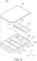
- FIG. 5 is a perspective view of a battery pack 1000 according to another exemplary embodiment
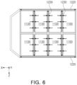
- FIG. 6 shows a flow path in the battery pack 1000 according to another exemplary embodiment
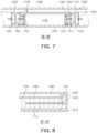
- FIG. 7 is a schematic cross-sectional view taken along line III-III' of the battery pack 1000 of FIG. 5
- FIG. 8 is a schematic cross-sectional view taken along line IV-IV' of the battery pack 1000 of FIG. 5 .
- a plurality of battery modules 1100 may be disposed in a pack housing 1200.
- Each of the plurality of battery modules 1100 may include a venting hole 1111 formed in a side surface.
- the pack housing 1200 may include a lower plate 1210, a side frame 1220 extended from an edge of the lower plate 1210, and an upper plate 1240 covering the battery modules 1100.
- the battery module 1100 of FIGS. 5 through 8 may include some or all of the components included in the battery module 100 described with reference to FIGS. 1 through 4 .
- the battery module 1100 may include battery cells 1130 and an outer cover 1110 surrounding at least some of the plurality of battery cells 1130.
- the battery module 1100 may include an insulating cover 1150 disposed on one side of the battery cell 1130, and the insulating cover 1150 may include a venting guide 1151. Flame or gas occurring in the battery cell 1130 may be emitted outward from the battery module 1100 through the venting guide 1151.
- the outer cover 1110 may include a venting hole 1111 corresponding to the venting guide 1151. The flame or gas occurring in the battery cell 1130 may be emitted through the venting guide 1151 and subsequently the venting hole 1111.
- the battery cell 1130 may include an electrode lead 1131 output in one direction, and the electrode lead 1131 may be connected to a bus-bar assembly 1140.
- the insulating cover 1150 may be disposed to face the bus-bar assembly 1140.
- the insulating cover 1150 may be disposed between the outer cover 1110 and the bus-bar assembly 1140, and the insulating cover 1150 and the outer cover 1110 may respectively include the venting guide 1151 and the venting hole 1111, which emit the gas or flame occurring in the battery cell 1130.
- the pack housing 1200 may include a partition wall 1230 partitioning an inner space of the pack housing. At least one battery module 1100 may be disposed in the space partitioned by the partition wall 1230. Referring to FIG. 6 , the flame or gas emitted from the battery module 1100 may be directed into the side frame 1220 through the partition wall 1230. The flame or gas flowing in the side frame 1220 may be ejected outward from the battery pack 1000 through a hole configured in the pack housing.
- the flame or gas occurring in the battery cell 130 may be emitted outwardly from the battery module 1100 through the venting guide 151 of the insulating cover 150 and the venting hole 1111 of the outer cover 1110.
- the emitted flame or gas may be introduced into a first flow path 1231 formed by the partition wall 1230.
- the first flow path 1231 may be extended in a length direction of the partition wall 1230.
- the partition wall 1230 may form two or more first flow paths 1231 spatially separated from each other.
- one partition wall 1230 may form two or more first flow paths 1231 spatially separated from each other by structural shape. Referring to FIG. 7 , the partition wall 1230 may define the first flow path 1231 disposed on each of two sides of the partition wall 1230.
- the partition wall 1230 may be formed in a shape of a beam having an "I"-shaped cross section, and define one flow path on each of the two sides thereof. Other partition wall 1230 shapes may be utilized in other examples.
- the side frame 1220 may form a second flow path 1221.
- the second flow path 1221 may be connected to the first flow path 1231 of the partition wall 1230.
- the second flow path 1221 may include an inner space of the side frame 1220.
- the side frame 1220 may be formed in a shape of a beam including an inner space and include a hole 1222 for communicating the first flow path 1231 of the partition 1230 and the internal space to each other.
- the gas or flame ejected from the venting hole 1111 may be primarily introduced into the first flow path 1231 of the partition 1230, and moved in the length direction of the partition 1230 along the first flow path 1231 to be secondarily introduced into the second flow path 1221 formed by the side frame 1220.
- the gas or flame introduced into the second flow path 1221 may be emitted outward from the pack housing 1200 through an output configured in the pack housing 1200.
- the battery module according to an exemplary embodiment of the present disclosure may emit the flame, gas, or dust occurring due to abnormal action of the battery cell, such as the thermal runaway, in the desired direction. This may improve safety of the battery module or battery pack.
Abstract
Description
- The present disclosure relates to technology related to a battery module and a battery pack.
- In a lithium secondary battery, several unit cells may be bundled to form a battery pack, and the battery pack may be widely applied to a field requiring high energy, such as a vehicle battery or an energy storage system(ESS).
- An aspect of the present disclosure may minimize a phenomenon in which thermal runaway of a battery cell in a battery module leads to thermal runaway of another battery cell or another battery module.
- Another aspect of the present disclosure may provide a battery module having a structure for emitting flame, gas or dust occurring due to an abnormal action of a battery cell such as thermal runaway in a secondary battery in a desired direction.
- According to an aspect of the present disclosure, a battery module may include: a plurality of battery cells; and an insulating cover disposed on one side of the plurality of battery cells, the insulating cover comprising a venting guide configured to emit flame or gas occurring in one or more of the plurality of battery cells.
- The battery module may further include a bus-bar assembly including the at least one bus-bar electrically connected to at least one of the plurality of battery cells, wherein the insulating cover may be disposed to face the bus-bar assembly.
- The battery module may further include a heat-resistant sheet disposed between the insulating cover and the bus-bar assembly.
- The plurality of battery cells may include electrode leads output in a first direction, the insulating cover may face the plurality of battery cells in the first direction, and the venting guide may pass through the insulating cover in the first direction.
- The battery module may further include a cover sheet disposed on the venting guide to prevent foreign material from being introduced into the venting guide.
- The battery module may further include an outer cover disposed on one side of the insulating cover and including at least one venting hole communicating with the venting guide.
- According to another aspect of the present disclosure, a battery pack may include: a pack housing; and a plurality of battery modules accommodated in the pack housing, wherein the battery module may include: a plurality of battery cells; and an insulating cover disposed on one side of the plurality of battery cells, the insulating cover comprising a venting guide configured to emit flame or gas occurring in one or more of the plurality of battery cells.
- The pack housing may include a partition wall partitioning an inner space of the pack housing, the partition wall forming a first flow path guiding the flame or gas emitted from the venting guide.
- The pack housing may include a lower plate and a side frame disposed on an edge of the lower plate, and the side frame may form a second flow path communicating with the first flow path.
- The battery pack may further include a bus-bar assembly including the at least one bus-bar electrically connected to the at least one of the plurality of battery cells, wherein the insulating cover may face the bus-bar assembly.
- The battery pack may further include a heat-resistant sheet disposed between the insulating cover and the bus-bar assembly.
- The plurality of battery cells may include electrode leads output in a first direction, the insulating cover may face the plurality of battery cells in the first direction, and the venting guide may pass through the insulating cover in the first direction.
- The battery pack may further include a cover sheet disposed on the venting guide to prevent foreign material from being introduced into the venting guide.
- The battery pack may further include an outer cover disposed on the insulating cover and including at least one venting hole communicating with the venting guide.
- The partition wall may form two first flow paths spatially separated from each other by its structural shape.
- The above and other aspects, features and advantages of the present disclosure will be more clearly understood from the following detailed description taken in conjunction with the accompanying drawings, in which:
-
FIG. 1 is a perspective view of a battery module according to an exemplary embodiment; -
FIG. 2 is an exploded perspective view of the battery module according to an exemplary embodiment; -
FIG. 3 is a schematic cross-sectional view taken along line I-I' of the battery module ofFIG. 1 ; -
FIG. 4 is a schematic cross-sectional view taken along line II-II' of the battery module ofFIG. 1 ; -
FIG. 5 is a perspective view of a battery pack according to another exemplary embodiment; -
FIG. 6 shows a flow path in the battery pack according to another exemplary embodiment; -
FIG. 7 is a schematic cross-sectional view taken along line III-III' of the battery pack ofFIG. 5 ; and -
FIG. 8 is a schematic cross-sectional view taken along line IV-IV' of the battery pack ofFIG. 5 . - Hereinafter, exemplary embodiments in the present disclosure will now be described in detail with reference to the accompanying drawings.
- In this specification, an X-direction, a Y-direction and a Z-direction may indicate a direction parallel to an X axis, a direction parallel to a Y axis, and a direction parallel to a Z axis, each shown in the drawings. In addition, unless otherwise described, the X-direction may be a concept including both a +X axis direction and a -X axis direction, which may be equally applied to the Y-direction and the Z-direction.
- Secondary batteries may take a variety of forms. In an example, a secondary battery may include a plurality of battery cells. The plurality of battery cells may be bundled to be an intermediate assembly such as a battery module, and the intermediate assemblies may be bundled to be a battery pack. The battery cell may have any of various shapes. For example, the battery cell may have a pouch-shaped outer case surrounding an electrode assembly. In another example, the battery cell may have the electrode assembly accommodated in a cylindrical or prismatic outer case.
- The electrode assembly included in the battery cell may have a plurality of electrodes stacked on each other. The electrode may include a current collector and an electrode mixture applied to a surface of the current collector. In some instances, a short circuit might occur between the electrodes due to an external impact or the like, which may lead to ignition of the battery cell. Flame or high-temperature gas emitted from the battery cell may cause serial ignition of another battery cell adjacent thereto. When the battery pack includes the plurality of battery modules, fire occurring in one battery module may lead to fire in the entire battery pack.
- Accordingly, there is a need for a method to effectively emit the flame or gas occurring in the battery cell to prevent the serial ignition of another battery cell and another battery module.
-
FIG. 1 is a perspective view of abattery module 100 according to an exemplary embodiment;FIG. 2 is an exploded perspective view of thebattery module 100 according to an exemplary embodiment;FIG. 3 is a schematic cross-sectional view taken along line I-I' of thebattery module 100 ofFIG. 1 ; andFIG. 4 is a schematic cross-sectional view taken along line II-II' of thebattery module 100 ofFIG. 1 . - In an exemplary embodiment, the
battery module 100 may include a plurality ofbattery cells 130 and aninsulating cover 150 disposed on one side of the plurality ofbattery cells 130. Theinsulating cover 150 may be made of an insulating material such as plastic. - Referring to
FIGS. 2 through 4 , theinsulating cover 150 in an exemplary embodiment may include aventing guide 151. Theventing guide 151 may provide a path for guiding and emitting flame or gas occurring in thebattery cell 130 disposed on one side of theinsulating cover 150 in a desired direction or position. For example, referring toFIG. 2 , theventing guide 151 may be open in the +X-direction, such that the flame or gas occurring in thebattery cell 130 may be limited or wholly prevented from being emitted in the Y-direction or the Z-direction, and emitted in the +X-direction. - In an exemplary embodiment, the
venting guide 151 may be open in a direction opposite to thebattery cells 130. For example, theinsulating cover 150 may be disposed to face thebattery cells 130 in the X-direction, and theventing guide 151 may be open in the X-direction. Accordingly, the flame or gas occurring in thebattery cell 130 may be emitted through theventing guide 151 away from thebattery cells 130. - In an exemplary embodiment, the
battery cell 130 may include anelectrode lead 131, and theventing guide 151 may be open in a direction in which theelectrode lead 131 is output. Referring toFIGS . 3 and 4 , theelectrode lead 131 may be output in the X-direction, and theventing guide 151 may be open in the X-direction. In some instances, an outer case surrounding an electrode assembly may have a relatively weak sealing strength at a portion where theelectrode lead 131 is output. In an instance where thebattery cell 130 is ignited, absent aventing guide 151, the gas or the flame might tend to be emitted in the direction in which theelectrode lead 131 of thebattery cell 130 is output. Theventing guide 151 may be open in the direction in which theelectrode lead 131 is output, and the flame or gas may thus be effectively emitted outward from thebattery module 100, which may prevent or delay a serial ignition or thermal runaway of thebattery cells 130. - In an exemplary embodiment, the
battery module 100 may include a bus-bar assembly 140 connected to thebattery cell 130. Thebattery module 100 may include the bus-bar assembly 140 disposed on one side of thebattery cell 130. The bus-bar assembly 140 may include at least one bus-bar 141 connected to thebattery cell 130. The bus-bar 141 may electrically connect two or moreadjacent battery cells 130. For example, theelectrode lead 131 output from thebattery cell 130 may be connected to the bus-bar 141. The bus-bar assembly 140 may include aninsulation plate 142, and the bus-bar 141 may be disposed on theinsulation plate 142. - In an exemplary embodiment, the bus-
bar assembly 140 and the insulatingcover 150 may be sequentially disposed on thebattery cell 130 in one direction. Any flame or gas ejected from thebattery cell 130 may damage the bus-bar assembly 140 disposed on one side of the insulatingcover 150, and then be emitted through the ventingguide 151 configured in the insulatingcover 150 to the other side of the insulating cover 150 (i.e., in the +X-direction). - In an exemplary embodiment, the insulating
cover 150 may be disposed to face the bus-bar assembly 140. For example, the bus-bar assembly 140 may be disposed on thebattery cell 130 in the +X-direction and the insulatingcover 150 may be disposed on the bus-bar assembly 140 in the +X-direction. In an exemplary embodiment, the insulatingcover 150 may include the ventingguide 151 open in a direction opposite to the bus-bar assembly 140. For example, the bus-bar assembly 140 and the insulatingcover 150 may face each other in the X-direction, and the ventingguide 151 may be open in the X-direction. - In an exemplary embodiment, the bus-
bar assembly 140 may be disposed in the direction in which theelectrode lead 131 is output. Referring toFIGS. 3 and 4 , theelectrode lead 131 may be output in the X-direction, and the bus-bar assembly 140 may be disposed on thebattery cell 130 in the +X-direction. The flame or gas occurring in thebattery cell 130 may be mainly emitted in the direction in which theelectrode lead 131 is output, and may damage the bus-bar assembly 140, and may be ejected out of thebattery module 100 through the ventingguide 151 configured in the insulatingcover 150 disposed on one side of the bus-bar assembly 140. - In an exemplary embodiment, the
battery module 100 may include the plurality ofbattery cells 130 andouter covers battery cells 130. The outer covers 110 and 120 may bundle thebattery cells 130 into one aggregate and protect thebattery cells 130 therein. The outer covers 110 and 120 may include several cover elements. For example, the outer covers 110 and 120 may include front andrear covers 110 and anupper cover 120. The front andrear covers 110 may each be disposed in the direction in which theelectrode lead 131 of thebattery cell 130 is output. Theupper cover 120 may partially cover a side surface of thebattery module 100. - The outer covers 110 and 120 may be made of a material having high strength to protect the
battery cells 130. The outer covers 110 and 120 may be made of a metal material such as aluminum, an aluminum alloy, or steel. - The insulating
cover 150 may be disposed between theouter covers battery cell 130 to insulate the outer covers 110, 120 and thebattery cell 130 from each other. - In an exemplary embodiment, the outer covers 110 and 120 may include a
venting hole 111 corresponding to the ventingguide 151. For example, the ventinghole 111 may communicate with the ventingguide 151. The gas or flame ejected through the ventingguide 151 of the insulatingcover 150 may escape outward from thebattery module 100 through theventing hole 111 of the front and rear covers 110. -
FIGS.1 through 4 each show that thebattery module 100 includes the outer covers 110 and 120. However, another exemplary embodiment may omit some or all of the outer covers 110 and 120. In this case, the insulatingcover 150 may partially form an exterior of thebattery module 100. - In an exemplary embodiment, the venting
guide 151 may have a structure more easily damaged than the other portions by the flame or gas ejected from thebattery cell 130. In an exemplary embodiment, the ventingguide 151 may pass through the insulatingcover 150. For example, the ventingguide 151 may be a hole. -
FIGS. 2 through 4 each show that the ventingguide 151 has a shape of a hole. However, the ventingguide 151 may not necessarily pass through the insulatingcover 150. The ventingguide 151 may be made more vulnerable to heat or pressure than the other portions. Accordingly, a portion of the insulatingcover 150 where the ventingguide 151 is formed may be pierced first by the flame or gas ejected from thebattery cell 130, and the flame or gas may thus be emitted through the corresponding portion. For example, the insulatingcover 150 may include a portion having a smaller thickness than the other portions, where the corresponding portion may function as the ventingguide 151. In this case, the portion functioning as the ventingguide 151 of the insulatingcover 150 may be more easily melted by the flame or high-temperature gas compared to other portions due to its smaller thickness to provide a flow path in which the flame or gas ejected from thebattery cell 130 is emitted. - Referring to
FIGS. 2 through 4 , thebattery cells 130 in an exemplary embodiment may be arranged in a first direction, and the plurality of venting guides 151 may be arranged in the first direction. For example, thebattery cells 130 may be arranged in the Z-direction, and the plurality of venting guides 151 may be arranged in the Z-direction. The size and number of the ventingguide 151 shown inFIG. 2 are only examples. In other embodiments, the ventingguide 151 may have any of various sizes and numbers. - In an exemplary embodiment, the front and
rear covers 110 each disposed on the insulatingcover 150 may include theventing hole 111 corresponding to the ventingguide 151. Referring toFIG. 2 , the front andrear covers 110 may each correspond to the ventingguide 151 and include the plurality of ventingholes 111 arranged in the Z-direction. The size and number of theventing hole 111 shown inFIG. 2 are exemplary. In other embodiments, ventingholes 111 may have differing sizes and numbers. - In an exemplary embodiment, a
cover sheet 160 may be disposed on the insulatingcover 150. Thecover sheet 160 may prevent foreign material outside thebattery module 100 from being introduced into theventing hole 111. - The
cover sheet 160 may block the introduction of the foreign material from outside thebattery module 100, while allowing flame or gas to be emitted through theventing hole 111. - In an exemplary embodiment, the
cover sheet 160 may be made of a material which may be more easily melted than the insulatingcover 150 by the flame or gas. For example, thecover sheet 160 may be made of a material such as polycarbonate. In another exemplary embodiment, thecover sheet 160 and the insulatingcover 150 may be integrally formed with each other. - Meanwhile, in an exemplary embodiment, the
battery module 100 may include a heat-resistant sheet 170 disposed between the bus-bar assembly 140 and the insulatingcover 150 to prevent the flame or gas partially emitted from the ventingguide 151 from being introduced into another ventingguide 151. The heat-resistant sheet 170 may be made of a material having fire resistance, heat resistance, or heat insulation characteristics. For example, the heat-resistant sheet 170 may be a ceramic fiber. - An exemplary embodiment may omit at least one of the
cover sheet 160 and the heat-resistant sheet 170. -
FIG. 5 is a perspective view of abattery pack 1000 according to another exemplary embodiment;FIG. 6 shows a flow path in thebattery pack 1000 according to another exemplary embodiment;FIG. 7 is a schematic cross-sectional view taken along line III-III' of thebattery pack 1000 ofFIG. 5 ; andFIG. 8 is a schematic cross-sectional view taken along line IV-IV' of thebattery pack 1000 ofFIG. 5 . - Referring to
FIG. 5 , a plurality ofbattery modules 1100 may be disposed in apack housing 1200. Each of the plurality ofbattery modules 1100 may include aventing hole 1111 formed in a side surface. Thepack housing 1200 may include alower plate 1210, aside frame 1220 extended from an edge of thelower plate 1210, and anupper plate 1240 covering thebattery modules 1100. - The
battery module 1100 ofFIGS. 5 through 8 may include some or all of the components included in thebattery module 100 described with reference toFIGS. 1 through 4 . - For example, referring to
FIG. 7 , thebattery module 1100 may includebattery cells 1130 and anouter cover 1110 surrounding at least some of the plurality ofbattery cells 1130. Thebattery module 1100 may include an insulatingcover 1150 disposed on one side of thebattery cell 1130, and the insulatingcover 1150 may include aventing guide 1151. Flame or gas occurring in thebattery cell 1130 may be emitted outward from thebattery module 1100 through the ventingguide 1151. Theouter cover 1110 may include aventing hole 1111 corresponding to theventing guide 1151. The flame or gas occurring in thebattery cell 1130 may be emitted through the ventingguide 1151 and subsequently theventing hole 1111. Thebattery cell 1130 may include anelectrode lead 1131 output in one direction, and theelectrode lead 1131 may be connected to a bus-bar assembly 1140. The insulatingcover 1150 may be disposed to face the bus-bar assembly 1140. - The insulating
cover 1150 may be disposed between theouter cover 1110 and the bus-bar assembly 1140, and the insulatingcover 1150 and theouter cover 1110 may respectively include theventing guide 1151 and theventing hole 1111, which emit the gas or flame occurring in thebattery cell 1130. - The
pack housing 1200 may include apartition wall 1230 partitioning an inner space of the pack housing. At least onebattery module 1100 may be disposed in the space partitioned by thepartition wall 1230. Referring toFIG. 6 , the flame or gas emitted from thebattery module 1100 may be directed into theside frame 1220 through thepartition wall 1230. The flame or gas flowing in theside frame 1220 may be ejected outward from thebattery pack 1000 through a hole configured in the pack housing. - Referring to
FIGS. 6 and7 , the flame or gas occurring in thebattery cell 130 may be emitted outwardly from thebattery module 1100 through the ventingguide 151 of the insulatingcover 150 and theventing hole 1111 of theouter cover 1110. The emitted flame or gas may be introduced into afirst flow path 1231 formed by thepartition wall 1230. Thefirst flow path 1231 may be extended in a length direction of thepartition wall 1230. - In another exemplary embodiment, the
partition wall 1230 may form two or morefirst flow paths 1231 spatially separated from each other. In another exemplary embodiment, onepartition wall 1230 may form two or morefirst flow paths 1231 spatially separated from each other by structural shape. Referring toFIG. 7 , thepartition wall 1230 may define thefirst flow path 1231 disposed on each of two sides of thepartition wall 1230. For example, thepartition wall 1230 may be formed in a shape of a beam having an "I"-shaped cross section, and define one flow path on each of the two sides thereof.Other partition wall 1230 shapes may be utilized in other examples. - Referring to
FIG. 8 , theside frame 1220 may form asecond flow path 1221. Thesecond flow path 1221 may be connected to thefirst flow path 1231 of thepartition wall 1230. In another exemplary embodiment, thesecond flow path 1221 may include an inner space of theside frame 1220. For example, theside frame 1220 may be formed in a shape of a beam including an inner space and include ahole 1222 for communicating thefirst flow path 1231 of thepartition 1230 and the internal space to each other. The gas or flame ejected from theventing hole 1111 may be primarily introduced into thefirst flow path 1231 of thepartition 1230, and moved in the length direction of thepartition 1230 along thefirst flow path 1231 to be secondarily introduced into thesecond flow path 1221 formed by theside frame 1220. The gas or flame introduced into thesecond flow path 1221 may be emitted outward from thepack housing 1200 through an output configured in thepack housing 1200. - As set forth above, according to an exemplary embodiment of the present disclosure, it may be possible to minimize the phenomenon in which the thermal runaway of a battery cell in the battery module leads to the thermal runaway of another battery cell or another battery module.
- In addition, the battery module according to an exemplary embodiment of the present disclosure may emit the flame, gas, or dust occurring due to abnormal action of the battery cell, such as the thermal runaway, in the desired direction. This may improve safety of the battery module or battery pack.
Claims (15)
- A battery module (100) comprising:a plurality of battery cells (130); andan insulating cover (150) disposed on one side of the plurality of battery cells (130), the insulating cover (150) comprising a venting guide (151) configured to emit flame or gas occurring in one or more of the plurality of battery cells (130) .
- The battery module (100)of claim 1, further comprising a bus-bar assembly (140) including at least one bus-bar (141) electrically connected to one or more of the plurality of battery cells (130),
wherein the insulating cover (150) faces the bus-bar assembly (140). - The battery module (100)of claim 2, further comprising a heat-resistant sheet (170) disposed between the insulating cover (150) and the bus-bar assembly(140).
- The battery module (100) of anyone of the preceding claims, wherein the plurality of battery cells (130) include electrode leads (131) output in a first direction, wherein the insulating cover (150) faces the plurality of battery cells (130) in the first direction, and wherein the venting guide (151) passes through the insulating cover (150) in the first direction.
- The battery module (100) of anyone of the preceding claims, further comprising a cover sheet (160) disposed on the venting guide (151) to prevent foreign material from being introduced into the venting guide (151).
- The battery module (100) of anyone of the preceding claims, further comprising an outer cover (110) disposed on one side of the insulating cover (150) and including at least one venting hole (111) communicating with the venting guide (151) .
- A battery pack (1000) comprising:a pack housing (1200); anda plurality of battery modules (1100) accommodated in the pack housing (1200),wherein one of the battery modules (1100) includes:a plurality of battery cells (1130); andan insulating cover (1150) disposed on one side of the plurality of battery cells (1130), the insulating cover (1150) comprising a venting guide (1151) configured to emit flame or gas occurring in one or more of the plurality of battery cells (1130).
- The battery pack (1000) of claim 7, wherein the pack housing (1200) includes a partition wall (1230) partitioning an inner space of the pack housing (1200), the partition wall (1230) forming a first flow path (1231) guiding the flame or gas emitted from the venting guide (1151).
- The battery pack (1000) of claim 8, wherein the pack housing (1200) includes a lower plate (1210) and a side frame (1220) disposed on an edge of the lower plate (1210), wherein the side frame (1220) forms a second flow path (1221) communicating with the first flow path (1231).
- The battery pack (1000) of anyone of claims 7 to 9, further comprising a bus-bar assembly (1140) including at least one bus-bar (1141) electrically connected to one or more of the plurality of battery cells(1130),
wherein the insulating cover (1150) faces the bus-bar assembly (1140). - The battery pack (1000) of anyone of claims 7 to 10, further comprising a heat-resistant sheet (1170) disposed between the insulating cover (1150) and the bus-bar assembly (1140).
- The battery pack (1000) of anyone of claims 7 to 11, wherein the plurality of battery cells (1130) include electrode leads (1131) output in a first direction, wherein the insulating cover (1150) faces the plurality of battery cells (1130) in the first direction, and wherein the venting guide (1151) passes through the insulating cover (1150) in the first direction.
- The battery pack (1000) of anyone of claims 7 to 12, wherein further comprising a cover sheet (1160) disposed on the venting guide (1151) to prevent foreign material from being introduced into the venting guide (1151).
- The battery pack (1000) of anyone of claims 7 to 13, further comprising an outer cover (1110) disposed on the insulating cover (1150) and including at least one venting hole (1111) communicating with the venting guide (1151).
- The battery pack (1000) of claim 8, wherein the partition wall (1230) forms two first flow paths (1231) spatially separated from each other by its structural shape.
Applications Claiming Priority (1)
| Application Number | Priority Date | Filing Date | Title |
|---|---|---|---|
| KR1020210129488A KR20230046463A (en) | 2021-09-30 | 2021-09-30 | battery module and battery pack having the same |
Publications (1)
| Publication Number | Publication Date |
|---|---|
| EP4160798A1 true EP4160798A1 (en) | 2023-04-05 |
Family
ID=83438524
Family Applications (1)
| Application Number | Title | Priority Date | Filing Date |
|---|---|---|---|
| EP22197094.0A Pending EP4160798A1 (en) | 2021-09-30 | 2022-09-22 | Battery module and battery pack having the same |
Country Status (4)
| Country | Link |
|---|---|
| US (1) | US20230102399A1 (en) |
| EP (1) | EP4160798A1 (en) |
| KR (1) | KR20230046463A (en) |
| CN (1) | CN115911672A (en) |
Citations (4)
| Publication number | Priority date | Publication date | Assignee | Title |
|---|---|---|---|---|
| US20100266880A1 (en) * | 2008-03-04 | 2010-10-21 | Panasonic Corporation | Battery module and battery pack using said battery module |
| US20120237803A1 (en) * | 2009-04-22 | 2012-09-20 | Tesla Motors, Inc. | Battery Pack Directed Venting System |
| US20210074972A1 (en) * | 2019-09-05 | 2021-03-11 | Samsung Sdi Co., Ltd. | Energy storage module |
| KR20210029125A (en) * | 2020-09-04 | 2021-03-15 | 삼성에스디아이 주식회사 | Energy Storage Module |
-
2021
- 2021-09-30 KR KR1020210129488A patent/KR20230046463A/en unknown
-
2022
- 2022-09-21 US US17/949,309 patent/US20230102399A1/en active Pending
- 2022-09-22 EP EP22197094.0A patent/EP4160798A1/en active Pending
- 2022-09-27 CN CN202211188482.9A patent/CN115911672A/en active Pending
Patent Citations (4)
| Publication number | Priority date | Publication date | Assignee | Title |
|---|---|---|---|---|
| US20100266880A1 (en) * | 2008-03-04 | 2010-10-21 | Panasonic Corporation | Battery module and battery pack using said battery module |
| US20120237803A1 (en) * | 2009-04-22 | 2012-09-20 | Tesla Motors, Inc. | Battery Pack Directed Venting System |
| US20210074972A1 (en) * | 2019-09-05 | 2021-03-11 | Samsung Sdi Co., Ltd. | Energy storage module |
| KR20210029125A (en) * | 2020-09-04 | 2021-03-15 | 삼성에스디아이 주식회사 | Energy Storage Module |
Also Published As
| Publication number | Publication date |
|---|---|
| KR20230046463A (en) | 2023-04-06 |
| CN115911672A (en) | 2023-04-04 |
| US20230102399A1 (en) | 2023-03-30 |
Similar Documents
| Publication | Publication Date | Title |
|---|---|---|
| JPWO2017130259A1 (en) | Battery pack | |
| CN112103424B (en) | Battery module, battery pack including the battery module, and energy storage system including the battery pack | |
| US20220302549A1 (en) | Battery module and battery pack including the same | |
| JP2023531844A (en) | Battery pack and device using the battery pack as a power supply | |
| JP2022545731A (en) | Battery modules and battery packs containing the same | |
| US11394067B2 (en) | Battery, battery enclosure and vehicle | |
| US20220352595A1 (en) | Battery module and battery pack including the same | |
| EP4160798A1 (en) | Battery module and battery pack having the same | |
| CN219067061U (en) | Battery pack | |
| KR20210127320A (en) | Battery pack and device including the same | |
| CN216850075U (en) | Battery module and battery pack | |
| CN117642917A (en) | Battery module and battery pack including the same | |
| KR20240023430A (en) | Batteries, electrical devices, methods and devices for manufacturing batteries | |
| KR20220000638A (en) | Battery module and battery pack including the same | |
| KR20220106379A (en) | Battery module and battery pack including the same | |
| EP4246683A1 (en) | End plate assembly including thermistor, battery module and battery pack including the same | |
| US20240030549A1 (en) | Battery module and battery pack including the same | |
| US20230067336A1 (en) | Cell Assembly Unit and Battery Pack Including the Same | |
| US20230378599A1 (en) | Battery module and battery pack including the same | |
| US20230097771A1 (en) | Battery pack | |
| US20230282931A1 (en) | Battery pack | |
| US20240072374A1 (en) | Battery module and battery pack comprising same | |
| KR20220125097A (en) | Battery module and battery pack including the same | |
| KR20240021501A (en) | Battery module having a structure capable of venting gas while preventing flame emission | |
| CN116261806A (en) | Battery module and battery pack including the same |
Legal Events
| Date | Code | Title | Description |
|---|---|---|---|
| PUAI | Public reference made under article 153(3) epc to a published international application that has entered the european phase |
Free format text: ORIGINAL CODE: 0009012 |
|
| STAA | Information on the status of an ep patent application or granted ep patent |
Free format text: STATUS: THE APPLICATION HAS BEEN PUBLISHED |
|
| AK | Designated contracting states |
Kind code of ref document: A1 Designated state(s): AL AT BE BG CH CY CZ DE DK EE ES FI FR GB GR HR HU IE IS IT LI LT LU LV MC MK MT NL NO PL PT RO RS SE SI SK SM TR |
|
| P01 | Opt-out of the competence of the unified patent court (upc) registered |
Effective date: 20230602 |
|
| STAA | Information on the status of an ep patent application or granted ep patent |
Free format text: STATUS: REQUEST FOR EXAMINATION WAS MADE |
|
| 17P | Request for examination filed |
Effective date: 20231002 |
|
| RBV | Designated contracting states (corrected) |
Designated state(s): AL AT BE BG CH CY CZ DE DK EE ES FI FR GB GR HR HU IE IS IT LI LT LU LV MC MK MT NL NO PL PT RO RS SE SI SK SM TR |