EP4160794A1 - Secondary battery - Google Patents
Secondary battery Download PDFInfo
- Publication number
- EP4160794A1 EP4160794A1 EP21812868.4A EP21812868A EP4160794A1 EP 4160794 A1 EP4160794 A1 EP 4160794A1 EP 21812868 A EP21812868 A EP 21812868A EP 4160794 A1 EP4160794 A1 EP 4160794A1
- Authority
- EP
- European Patent Office
- Prior art keywords
- terminal
- insulating member
- plate
- cap
- anode
- Prior art date
- Legal status (The legal status is an assumption and is not a legal conclusion. Google has not performed a legal analysis and makes no representation as to the accuracy of the status listed.)
- Pending
Links
- 230000000712 assembly Effects 0.000 claims abstract description 27
- 238000000429 assembly Methods 0.000 claims abstract description 27
- 239000011810 insulating material Substances 0.000 claims description 23
- 238000004804 winding Methods 0.000 claims description 7
- 238000002347 injection Methods 0.000 description 6
- 239000007924 injection Substances 0.000 description 6
- 229910052751 metal Inorganic materials 0.000 description 5
- 239000002184 metal Substances 0.000 description 5
- OKTJSMMVPCPJKN-UHFFFAOYSA-N Carbon Chemical compound [C] OKTJSMMVPCPJKN-UHFFFAOYSA-N 0.000 description 4
- 239000003792 electrolyte Substances 0.000 description 4
- -1 polyethylene Polymers 0.000 description 4
- 238000004519 manufacturing process Methods 0.000 description 3
- 239000000758 substrate Substances 0.000 description 3
- 229910000838 Al alloy Inorganic materials 0.000 description 2
- PXHVJJICTQNCMI-UHFFFAOYSA-N Nickel Chemical compound [Ni] PXHVJJICTQNCMI-UHFFFAOYSA-N 0.000 description 2
- 239000004698 Polyethylene Substances 0.000 description 2
- 239000004743 Polypropylene Substances 0.000 description 2
- 229910052782 aluminium Inorganic materials 0.000 description 2
- XAGFODPZIPBFFR-UHFFFAOYSA-N aluminium Chemical compound [Al] XAGFODPZIPBFFR-UHFFFAOYSA-N 0.000 description 2
- 239000006183 anode active material Substances 0.000 description 2
- 230000002457 bidirectional effect Effects 0.000 description 2
- 229910052799 carbon Inorganic materials 0.000 description 2
- 239000006182 cathode active material Substances 0.000 description 2
- 239000011248 coating agent Substances 0.000 description 2
- 238000000576 coating method Methods 0.000 description 2
- 230000008878 coupling Effects 0.000 description 2
- 238000010168 coupling process Methods 0.000 description 2
- 238000005859 coupling reaction Methods 0.000 description 2
- 239000011888 foil Substances 0.000 description 2
- 229910002804 graphite Inorganic materials 0.000 description 2
- 239000010439 graphite Substances 0.000 description 2
- 230000037431 insertion Effects 0.000 description 2
- 238000003780 insertion Methods 0.000 description 2
- 238000009413 insulation Methods 0.000 description 2
- 229920000573 polyethylene Polymers 0.000 description 2
- 229920001155 polypropylene Polymers 0.000 description 2
- 238000003466 welding Methods 0.000 description 2
- RYGMFSIKBFXOCR-UHFFFAOYSA-N Copper Chemical compound [Cu] RYGMFSIKBFXOCR-UHFFFAOYSA-N 0.000 description 1
- 229910000881 Cu alloy Inorganic materials 0.000 description 1
- 229910000570 Cupronickel Inorganic materials 0.000 description 1
- HBBGRARXTFLTSG-UHFFFAOYSA-N Lithium ion Chemical compound [Li+] HBBGRARXTFLTSG-UHFFFAOYSA-N 0.000 description 1
- 229910000990 Ni alloy Inorganic materials 0.000 description 1
- 229910000831 Steel Inorganic materials 0.000 description 1
- 238000006243 chemical reaction Methods 0.000 description 1
- 239000002131 composite material Substances 0.000 description 1
- 229910052802 copper Inorganic materials 0.000 description 1
- 239000010949 copper Substances 0.000 description 1
- 230000000694 effects Effects 0.000 description 1
- 230000017525 heat dissipation Effects 0.000 description 1
- 235000015110 jellies Nutrition 0.000 description 1
- 239000008274 jelly Substances 0.000 description 1
- 229910001416 lithium ion Inorganic materials 0.000 description 1
- 239000000463 material Substances 0.000 description 1
- 238000007789 sealing Methods 0.000 description 1
- 238000004904 shortening Methods 0.000 description 1
- 239000000243 solution Substances 0.000 description 1
- 239000010959 steel Substances 0.000 description 1
- 230000008961 swelling Effects 0.000 description 1
Images


Classifications
-
- H—ELECTRICITY
- H01—ELECTRIC ELEMENTS
- H01M—PROCESSES OR MEANS, e.g. BATTERIES, FOR THE DIRECT CONVERSION OF CHEMICAL ENERGY INTO ELECTRICAL ENERGY
- H01M50/00—Constructional details or processes of manufacture of the non-active parts of electrochemical cells other than fuel cells, e.g. hybrid cells
- H01M50/10—Primary casings; Jackets or wrappings
- H01M50/147—Lids or covers
- H01M50/148—Lids or covers characterised by their shape
- H01M50/15—Lids or covers characterised by their shape for prismatic or rectangular cells
-
- H—ELECTRICITY
- H01—ELECTRIC ELEMENTS
- H01M—PROCESSES OR MEANS, e.g. BATTERIES, FOR THE DIRECT CONVERSION OF CHEMICAL ENERGY INTO ELECTRICAL ENERGY
- H01M10/00—Secondary cells; Manufacture thereof
- H01M10/04—Construction or manufacture in general
-
- H—ELECTRICITY
- H01—ELECTRIC ELEMENTS
- H01M—PROCESSES OR MEANS, e.g. BATTERIES, FOR THE DIRECT CONVERSION OF CHEMICAL ENERGY INTO ELECTRICAL ENERGY
- H01M10/00—Secondary cells; Manufacture thereof
- H01M10/04—Construction or manufacture in general
- H01M10/0431—Cells with wound or folded electrodes
-
- H—ELECTRICITY
- H01—ELECTRIC ELEMENTS
- H01M—PROCESSES OR MEANS, e.g. BATTERIES, FOR THE DIRECT CONVERSION OF CHEMICAL ENERGY INTO ELECTRICAL ENERGY
- H01M10/00—Secondary cells; Manufacture thereof
- H01M10/05—Accumulators with non-aqueous electrolyte
- H01M10/058—Construction or manufacture
- H01M10/0587—Construction or manufacture of accumulators having only wound construction elements, i.e. wound positive electrodes, wound negative electrodes and wound separators
-
- H—ELECTRICITY
- H01—ELECTRIC ELEMENTS
- H01M—PROCESSES OR MEANS, e.g. BATTERIES, FOR THE DIRECT CONVERSION OF CHEMICAL ENERGY INTO ELECTRICAL ENERGY
- H01M50/00—Constructional details or processes of manufacture of the non-active parts of electrochemical cells other than fuel cells, e.g. hybrid cells
- H01M50/10—Primary casings; Jackets or wrappings
- H01M50/102—Primary casings; Jackets or wrappings characterised by their shape or physical structure
- H01M50/103—Primary casings; Jackets or wrappings characterised by their shape or physical structure prismatic or rectangular
-
- H—ELECTRICITY
- H01—ELECTRIC ELEMENTS
- H01M—PROCESSES OR MEANS, e.g. BATTERIES, FOR THE DIRECT CONVERSION OF CHEMICAL ENERGY INTO ELECTRICAL ENERGY
- H01M50/00—Constructional details or processes of manufacture of the non-active parts of electrochemical cells other than fuel cells, e.g. hybrid cells
- H01M50/10—Primary casings; Jackets or wrappings
- H01M50/147—Lids or covers
-
- H—ELECTRICITY
- H01—ELECTRIC ELEMENTS
- H01M—PROCESSES OR MEANS, e.g. BATTERIES, FOR THE DIRECT CONVERSION OF CHEMICAL ENERGY INTO ELECTRICAL ENERGY
- H01M50/00—Constructional details or processes of manufacture of the non-active parts of electrochemical cells other than fuel cells, e.g. hybrid cells
- H01M50/10—Primary casings; Jackets or wrappings
- H01M50/172—Arrangements of electric connectors penetrating the casing
- H01M50/174—Arrangements of electric connectors penetrating the casing adapted for the shape of the cells
- H01M50/176—Arrangements of electric connectors penetrating the casing adapted for the shape of the cells for prismatic or rectangular cells
-
- H—ELECTRICITY
- H01—ELECTRIC ELEMENTS
- H01M—PROCESSES OR MEANS, e.g. BATTERIES, FOR THE DIRECT CONVERSION OF CHEMICAL ENERGY INTO ELECTRICAL ENERGY
- H01M50/00—Constructional details or processes of manufacture of the non-active parts of electrochemical cells other than fuel cells, e.g. hybrid cells
- H01M50/50—Current conducting connections for cells or batteries
- H01M50/528—Fixed electrical connections, i.e. not intended for disconnection
-
- H—ELECTRICITY
- H01—ELECTRIC ELEMENTS
- H01M—PROCESSES OR MEANS, e.g. BATTERIES, FOR THE DIRECT CONVERSION OF CHEMICAL ENERGY INTO ELECTRICAL ENERGY
- H01M50/00—Constructional details or processes of manufacture of the non-active parts of electrochemical cells other than fuel cells, e.g. hybrid cells
- H01M50/50—Current conducting connections for cells or batteries
- H01M50/531—Electrode connections inside a battery casing
- H01M50/533—Electrode connections inside a battery casing characterised by the shape of the leads or tabs
-
- H—ELECTRICITY
- H01—ELECTRIC ELEMENTS
- H01M—PROCESSES OR MEANS, e.g. BATTERIES, FOR THE DIRECT CONVERSION OF CHEMICAL ENERGY INTO ELECTRICAL ENERGY
- H01M50/00—Constructional details or processes of manufacture of the non-active parts of electrochemical cells other than fuel cells, e.g. hybrid cells
- H01M50/50—Current conducting connections for cells or batteries
- H01M50/531—Electrode connections inside a battery casing
- H01M50/534—Electrode connections inside a battery casing characterised by the material of the leads or tabs
-
- H—ELECTRICITY
- H01—ELECTRIC ELEMENTS
- H01M—PROCESSES OR MEANS, e.g. BATTERIES, FOR THE DIRECT CONVERSION OF CHEMICAL ENERGY INTO ELECTRICAL ENERGY
- H01M50/00—Constructional details or processes of manufacture of the non-active parts of electrochemical cells other than fuel cells, e.g. hybrid cells
- H01M50/50—Current conducting connections for cells or batteries
- H01M50/531—Electrode connections inside a battery casing
- H01M50/536—Electrode connections inside a battery casing characterised by the method of fixing the leads to the electrodes, e.g. by welding
-
- H—ELECTRICITY
- H01—ELECTRIC ELEMENTS
- H01M—PROCESSES OR MEANS, e.g. BATTERIES, FOR THE DIRECT CONVERSION OF CHEMICAL ENERGY INTO ELECTRICAL ENERGY
- H01M50/00—Constructional details or processes of manufacture of the non-active parts of electrochemical cells other than fuel cells, e.g. hybrid cells
- H01M50/50—Current conducting connections for cells or batteries
- H01M50/531—Electrode connections inside a battery casing
- H01M50/538—Connection of several leads or tabs of wound or folded electrode stacks
-
- H—ELECTRICITY
- H01—ELECTRIC ELEMENTS
- H01M—PROCESSES OR MEANS, e.g. BATTERIES, FOR THE DIRECT CONVERSION OF CHEMICAL ENERGY INTO ELECTRICAL ENERGY
- H01M50/00—Constructional details or processes of manufacture of the non-active parts of electrochemical cells other than fuel cells, e.g. hybrid cells
- H01M50/50—Current conducting connections for cells or batteries
- H01M50/531—Electrode connections inside a battery casing
- H01M50/54—Connection of several leads or tabs of plate-like electrode stacks, e.g. electrode pole straps or bridges
-
- H—ELECTRICITY
- H01—ELECTRIC ELEMENTS
- H01M—PROCESSES OR MEANS, e.g. BATTERIES, FOR THE DIRECT CONVERSION OF CHEMICAL ENERGY INTO ELECTRICAL ENERGY
- H01M50/00—Constructional details or processes of manufacture of the non-active parts of electrochemical cells other than fuel cells, e.g. hybrid cells
- H01M50/50—Current conducting connections for cells or batteries
- H01M50/543—Terminals
- H01M50/547—Terminals characterised by the disposition of the terminals on the cells
- H01M50/548—Terminals characterised by the disposition of the terminals on the cells on opposite sides of the cell
-
- H—ELECTRICITY
- H01—ELECTRIC ELEMENTS
- H01M—PROCESSES OR MEANS, e.g. BATTERIES, FOR THE DIRECT CONVERSION OF CHEMICAL ENERGY INTO ELECTRICAL ENERGY
- H01M50/00—Constructional details or processes of manufacture of the non-active parts of electrochemical cells other than fuel cells, e.g. hybrid cells
- H01M50/50—Current conducting connections for cells or batteries
- H01M50/543—Terminals
- H01M50/547—Terminals characterised by the disposition of the terminals on the cells
- H01M50/55—Terminals characterised by the disposition of the terminals on the cells on the same side of the cell
-
- H—ELECTRICITY
- H01—ELECTRIC ELEMENTS
- H01M—PROCESSES OR MEANS, e.g. BATTERIES, FOR THE DIRECT CONVERSION OF CHEMICAL ENERGY INTO ELECTRICAL ENERGY
- H01M50/00—Constructional details or processes of manufacture of the non-active parts of electrochemical cells other than fuel cells, e.g. hybrid cells
- H01M50/50—Current conducting connections for cells or batteries
- H01M50/543—Terminals
- H01M50/552—Terminals characterised by their shape
- H01M50/553—Terminals adapted for prismatic, pouch or rectangular cells
-
- H—ELECTRICITY
- H01—ELECTRIC ELEMENTS
- H01M—PROCESSES OR MEANS, e.g. BATTERIES, FOR THE DIRECT CONVERSION OF CHEMICAL ENERGY INTO ELECTRICAL ENERGY
- H01M50/00—Constructional details or processes of manufacture of the non-active parts of electrochemical cells other than fuel cells, e.g. hybrid cells
- H01M50/50—Current conducting connections for cells or batteries
- H01M50/543—Terminals
- H01M50/562—Terminals characterised by the material
-
- H—ELECTRICITY
- H01—ELECTRIC ELEMENTS
- H01M—PROCESSES OR MEANS, e.g. BATTERIES, FOR THE DIRECT CONVERSION OF CHEMICAL ENERGY INTO ELECTRICAL ENERGY
- H01M50/00—Constructional details or processes of manufacture of the non-active parts of electrochemical cells other than fuel cells, e.g. hybrid cells
- H01M50/50—Current conducting connections for cells or batteries
- H01M50/543—Terminals
- H01M50/564—Terminals characterised by their manufacturing process
- H01M50/566—Terminals characterised by their manufacturing process by welding, soldering or brazing
-
- H—ELECTRICITY
- H01—ELECTRIC ELEMENTS
- H01M—PROCESSES OR MEANS, e.g. BATTERIES, FOR THE DIRECT CONVERSION OF CHEMICAL ENERGY INTO ELECTRICAL ENERGY
- H01M50/00—Constructional details or processes of manufacture of the non-active parts of electrochemical cells other than fuel cells, e.g. hybrid cells
- H01M50/50—Current conducting connections for cells or batteries
- H01M50/543—Terminals
- H01M50/564—Terminals characterised by their manufacturing process
- H01M50/567—Terminals characterised by their manufacturing process by fixing means, e.g. screws, rivets or bolts
-
- H—ELECTRICITY
- H01—ELECTRIC ELEMENTS
- H01M—PROCESSES OR MEANS, e.g. BATTERIES, FOR THE DIRECT CONVERSION OF CHEMICAL ENERGY INTO ELECTRICAL ENERGY
- H01M50/00—Constructional details or processes of manufacture of the non-active parts of electrochemical cells other than fuel cells, e.g. hybrid cells
- H01M50/50—Current conducting connections for cells or batteries
- H01M50/572—Means for preventing undesired use or discharge
- H01M50/584—Means for preventing undesired use or discharge for preventing incorrect connections inside or outside the batteries
- H01M50/59—Means for preventing undesired use or discharge for preventing incorrect connections inside or outside the batteries characterised by the protection means
- H01M50/593—Spacers; Insulating plates
-
- H—ELECTRICITY
- H01—ELECTRIC ELEMENTS
- H01M—PROCESSES OR MEANS, e.g. BATTERIES, FOR THE DIRECT CONVERSION OF CHEMICAL ENERGY INTO ELECTRICAL ENERGY
- H01M50/00—Constructional details or processes of manufacture of the non-active parts of electrochemical cells other than fuel cells, e.g. hybrid cells
- H01M50/60—Arrangements or processes for filling or topping-up with liquids; Arrangements or processes for draining liquids from casings
- H01M50/609—Arrangements or processes for filling with liquid, e.g. electrolytes
- H01M50/627—Filling ports
-
- Y—GENERAL TAGGING OF NEW TECHNOLOGICAL DEVELOPMENTS; GENERAL TAGGING OF CROSS-SECTIONAL TECHNOLOGIES SPANNING OVER SEVERAL SECTIONS OF THE IPC; TECHNICAL SUBJECTS COVERED BY FORMER USPC CROSS-REFERENCE ART COLLECTIONS [XRACs] AND DIGESTS
- Y02—TECHNOLOGIES OR APPLICATIONS FOR MITIGATION OR ADAPTATION AGAINST CLIMATE CHANGE
- Y02E—REDUCTION OF GREENHOUSE GAS [GHG] EMISSIONS, RELATED TO ENERGY GENERATION, TRANSMISSION OR DISTRIBUTION
- Y02E60/00—Enabling technologies; Technologies with a potential or indirect contribution to GHG emissions mitigation
- Y02E60/10—Energy storage using batteries
-
- Y—GENERAL TAGGING OF NEW TECHNOLOGICAL DEVELOPMENTS; GENERAL TAGGING OF CROSS-SECTIONAL TECHNOLOGIES SPANNING OVER SEVERAL SECTIONS OF THE IPC; TECHNICAL SUBJECTS COVERED BY FORMER USPC CROSS-REFERENCE ART COLLECTIONS [XRACs] AND DIGESTS
- Y02—TECHNOLOGIES OR APPLICATIONS FOR MITIGATION OR ADAPTATION AGAINST CLIMATE CHANGE
- Y02P—CLIMATE CHANGE MITIGATION TECHNOLOGIES IN THE PRODUCTION OR PROCESSING OF GOODS
- Y02P70/00—Climate change mitigation technologies in the production process for final industrial or consumer products
- Y02P70/50—Manufacturing or production processes characterised by the final manufactured product
Definitions
- An embodiment of the present invention relates to a prismatic secondary battery having a bidirectional terminal.
- a secondary battery includes an electrode assembly having a cathode, a anode, and a separator interposed between the cathode and the anode, a case having one side open to receive the electrode assembly together with an electrolyte, and a cap assembly sealing an open side of the case.
- a cap assembly of a secondary battery includes a cathode terminal and an anode terminal which are electrically connected to the cathode and the anode of the electrode assembly. Any one of the cathode terminal and the anode terminal is different in the direction from the electrode tab of the electrode assembly, and thus the shape of the current collector connecting the electrode tab and the terminal of the cap assembly is complicated and the length thereof is increased.
- the present invention provides a secondary battery in which cap assemblies are formed at the opposite sides of a case and thus cathode and anode terminals of the cap assemblies can have the same direction as the cathode and anode tabs of the electrode assembly.
- a secondary battery includes: an electrode assembly which has an anode tab formed at one end thereof and a cathode tab formed at the other end thereof; a case in which the electrode assembly is received and which is open at both opposite ends thereof; and a pair of cap assemblies which are coupled to the respective open ends of the case.
- the anode tab and the cathode tab are disposed at the respective opposite ends in the longitudinal direction of a winding axis of the electrode assembly.
- the case has the longitudinally opposite ends opened.
- the cap assemblies may include an anode cap assembly having a cap plate coupled to one end of the case, an anode terminal formed on the cap plate and electrically connected to the anode tab, a cathode cap assembly having a cap plate coupled to the other end of the case, and a cathode terminal formed on the cap plate and electrically connected to the cathode tab.
- Each of the anode terminal and the cathode terminal may include a terminal plate electrically connected to an external terminal, a current collector electrically connected to the anode tab or the cathode tab, and a terminal pin coupled to the current collector and the terminal plate and electrically connecting the current collector and the terminal plate.
- Each of the cap assemblies may include a first insulating member made of an insulating material, which is disposed between the terminal plate and the cap plate of each of the anode terminal and the cathode terminal, a second insulating member made of an insulating material, which is disposed between the terminal pin and the cap plate, a third insulating member made of an insulating material, which is disposed between the cap plate and the electrode assembly, and a fourth insulating member made of an insulating material, which is disposed between the third insulating member and the electrode assembly.
- Each of the cap assemblies may include a first insulating member made of an insulating material disposed between the terminal plate and the cap plate of the anode terminal, a second insulating member made of an insulating material, which is disposed between the terminal pin and the cap plate, a third insulating member made of an insulating material, which is disposed between the cap plate and the electrode assembly, and a fourth insulating member made of an insulating material disposed between the third insulating member and the electrode assembly, wherein the third insulating member made of an insulating material, which is disposed between the cap plate of the cathode terminal and the electrode assembly, and the fourth insulating member made of an insulating material disposed between the third insulating member and the electrode assembly, are included.
- Each of the fourth insulating members has a slit, into which the anode tab or the cathode tab is inserted, formed through a plate surface.
- the anode tab or the cathode tab is electrically connected to the current collector between the third insulating member and the fourth insulating member.
- the present invention provides a secondary battery comprising: an electrode assembly in which electrode tabs having different polarities are formed at longitudinally opposite ends, respectively; a case in which the electrode assembly is received and which is open at longitudinally opposite ends thereof; and a pair of cap assemblies which are coupled to the respective open opposite ends of the case.
- Each of the cap assemblies includes a cap plate coupled to the open end of the case, a terminal formed on the cap plate and electrically connected to the electrode tab, and a plurality of insulating members made of an insulating material.
- the terminal includes a terminal plate electrically connected to an external terminal, a current collector electrically connected to the electrode tab, and a terminal pin coupled to the current collector and the terminal plate to electrically connect the current collector and the terminal plate.
- Each of the cap assemblies includes a first insulating member disposed between the terminal plate and the cap plate, a second insulating member disposed between the terminal pin and the cap plate, a third insulating member disposed between the cap plate and the electrode assembly, and a fourth insulating member disposed between the third insulating member and the electrode assembly.
- the fourth insulating member has a slit, into which the electrode tab is inserted, formed through the plate surface.
- the electrode tab is electrically connected to the current collector between the third insulating member and the fourth insulating member.
- cathode and anode tabs of an electrode assembly and cathode and anode terminals of each of the cap assemblies have the same directions, thereby simplifying the shape of a current collector and minimizing the length thereof.
- terminals are formed in both directions of the secondary battery, and thus the degree of assembly freedom in the longitudinal direction of the secondary battery is improved, thereby greatly increasing the length of the secondary battery.
- first, second, etc. may be used herein to describe various members, elements, regions, layers and/or sections, these members, elements, regions, layers and/or sections should not be limited by these terms. These terms are only used to distinguish one member, element, region, layer and/or section from another. Thus, for example, a first member, a first element, a first region, a first layer and/or a first section discussed below could be termed a second member, a second element, a second region, a second layer and/or a second section without departing from the teachings of the present disclosure.
- spatially relative terms such as “beneath,” “below,” “lower,” “above,” “upper,” and the like, may be used herein for ease of description to describe one element or feature's relationship to another element(s) or feature(s) as illustrated in the figures. It will be understood that the spatially relative terms are intended to encompass different orientations of the device in use or operation in addition to the orientation depicted in the figures. For example, if the element or feature in the figures is turned over, elements described as “below” or “beneath” other elements or features would then be oriented “on” or “above” the other elements or features. Thus, the exemplary term “below” can encompass both an orientation of above and below.
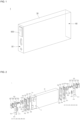
- FIG. 1 is a perspective view illustrating a secondary battery according to an embodiment of the present invention.
- FIG. 2 is a partially exploded perspective view of the secondary battery illustrated in FIG. 1 .
- FIG. 3 is a longitudinal cross-sectional view of the secondary battery illustrated in FIG. 1 .
- the secondary battery 1 may include an electrode assembly 10, a case 30, and a pair of cap assemblies 50 and 60.
- the electrode assembly 10 is received in the case 30 having opposite ends opened, and cap assemblies 50 and 60 are coupled to each of the opened opposite ends to seal the case 30.
- the electrode assembly 10 may be formed by stacking or winding an anode plate 11a, a separator, and a cathode plate 13a, which are formed in a thin plate shape or a film shape.
- the anode plate 11a may be formed by coating an anode active material such as graphite or carbon on an anode substrate formed of a metal foil such as copper, a copper alloy, nickel, or a nickel alloy.
- An anode uncoated region to which the anode active material is not applied may be formed in some regions of the anode substrate.
- An anode tab 11b is formed on the anode uncoated region, and the anode tab 11b and an anode terminal 520 to be described later may be electrically connected to each other by an anode current collector to be described later.
- the anode tab 11b may be formed to face one side along the longitudinal direction of a winding axis of the electrode assembly 10.
- the cathode plate 13a may be formed by coating a cathode active material such as graphite or carbon on a cathode formed of a metal foil such as aluminum or an aluminum alloy.
- a cathode uncoated region to which the cathode active material is not applied may be formed in some regions of the cathode substrate.
- a cathode tab 13b is formed on the cathode uncoated region, and the cathode tab 13b and a cathode terminal 620 to be described later may be electrically connected to each other by a cathode current collector to be described later.
- the cathode tab 13b may be formed to face the other side along the longitudinal direction of the winding axis of the electrode assembly 10.
- anode tab 11b and cathode tab 13b are disposed to face each other in opposite directions along the longitudinal direction of the winding axis of the electrode assembly 10.
- the anode tab 11b and the cathode tab 13b may be disposed to face opposite directions along the longitudinal direction of the secondary battery 1 with reference to FIG. 1 .
- the separator is disposed between the anode plate 11a and the cathode plate 13a to prevent short circuit and enable movement of lithium ions.
- the separator may be made of polyethylene, polypropylene, a composite film of polyethylene and polypropylene, or the like, but is not limited thereto.
- the case 30 may be formed of a conductive metal such as aluminum, an aluminum alloy, or nickel-plated steel.
- the case 30 may have a rectangular parallelepiped shape, and longitudinally opposite ends thereof may be opened.
- the electrode assembly 10 is received in the case 30 together with the electrolyte, and the cap assemblies 50 and 60 are coupled to the respective open opposite ends to seal the case 30.
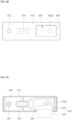
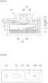
- FIG. 4A is a cross-sectional view of an anode terminal portion of a cap assembly illustrated in FIG. 1 .
- FIG. 4B is a plan view of the cap assembly illustrated in FIG. 4A .
- FIG. 4C is a rear view of the cap assembly illustrated in FIG. 4A .
- the anode cap assembly 50 may include a cap plate 510, an anode terminal 520, and a plurality of insulating members 526, 528, 540, and 550.
- the cap plate 510 seals an opening of the case 30 and may be made of the same material as the case 30.
- the cap plate 510 may have a rectangular parallelepiped shape corresponding to the shape of the opening of the case 30.
- the cap plate 510 may be coupled to the case 30 by laser welding.
- An injection port 512 and an anode safety vent 514 are formed in the cap plate 510, and the anode terminal 520 may be coupled thereto.
- the injection port 512 is a hole for injecting the electrolyte into the case 30, and may be sealed by a separate stopper, etc.
- the anode safety vent 514 has a notch formed to be opened at a set pressure, and serves to discharge gas when the internal pressure of the secondary battery 1 rises.
- the anode terminal 520 includes a terminal plate 522, a terminal pin 524, first and second insulating members 526 and 528, and an anode current collector 530.
- the terminal plate 522 is formed on the plate surface of the cap plate 510 exposed to the outside (for convenience, to be defined as an outer surface), and has a substantially rectangular plate shape.
- the terminal plate 522 is also called an anode terminal, is formed of metal and is electrically connected to an external terminal.
- the terminal plate 522 may be electrically connected to the anode current collector 530 by a terminal pin 524.
- a coupling portion in the form of a through hole or groove to which the terminal pin 524 is coupled may be formed on the lower surface of the terminal plate 522 (the lower surface of FIG. 4A ).
- a first insulating member 526 is inserted between the terminal plate 522 and the cap assembly 50.
- the first insulating member 526 has a plate shape corresponding to the shape of the terminal plate 522, and insulates the terminal plate 522 and the cap plate 510 from each other to prevent a short circuit therebetween.
- the terminal pin 524 has a shape similar to a bolt, and electrically connects the anode current collector 530 and the terminal plate 522.
- a ringshaped second insulating member 528 having a predetermined width is inserted between the terminal pin 524 and the cap plate 510 to insulate the terminal pin 524 and the cap plate 510 from each other.
- the terminal pin 524 While being coupled to the anode current collector 530, the terminal pin 524 has one end sequentially passing through the second insulating member 528, the cap plate 510, and the first insulating member 526 to then extend to and contact the terminal plate 522.
- the anode current collector 530 is disposed between the third and fourth insulating members 540 and 550 to be described later, and is electrically connected to the anode terminal 520 and the anode tab 11b.
- the anode current collector 530 has a strip (small plate) shape having a predetermined size, and is formed of a conductive metal.
- a pin coupling part to which a terminal pin is coupled is formed on one side of the anode current collector 530, and the other side of the anode current collector 530 may be curved or bent to be electrically connected to the anode tab 11b.
- the anode current collector 530 is composed of a thin plate-shaped main current collector plate 532 in which the pin insertion part 532a is formed and a thin plate-shaped auxiliary current collector plate 534 which is electrically connected to the anode tab 11b, and the main current collector plate 532 and the auxiliary current collector plate 534 may be electrically connected thereto (two anode current collectors are shown in the drawing).
- the main current collecting plate 532 and the auxiliary current collecting plate 534, and the main current collecting plate 532 and the anode tab 11b, may be connected by, but not limited to, laser welding.
- the third and fourth insulating members 540 and 550 are made of an insulating material and have a plate shape corresponding to the shape of the cap plate 510.
- the third insulating member 540 and the fourth insulating member 550 may be formed to have different sizes and heights of slits or holes formed through the plate surface.
- the third insulating member 540 is provided between the inner surface of the cap plate 510 and the electrode assembly 10 to insulate the cap plate 510 and the electrode assembly 10 from each other to prevent a short circuit therebetween.
- a first through hole 542 and a second through hole 544 are formed on the third insulating member 540 to correspond to the positions of the injection port 512 and the anode safety vent 514 described above. Electrolyte injection and gas movement are performed through the first through hole 542 and the second through hole 544.
- a third through hole 546 through which the aforementioned terminal pin 524 passes is formed on the third insulating member 540.
- a terminal pin 524 coupled to the main current collector plate 532 disposed between the third insulating member 540 and the fourth insulating member 550 through the third through hole 546 may extend to the terminal plate 522.
- the fourth insulating member 550 is provided between the third insulating member 540 and the electrode assembly 10 for insulation of an end of the electrode assembly 10.
- the height of the fourth insulating member 550 (H1, the vertical width based on FIG. 4A ) forms a space for the main current collecting plate 532 and the auxiliary current collecting plate 534, and thus may be formed higher than the height of the third insulating member 540.
- a slit 552 through which the anode tab 11b passes, a fourth through hole 554 and a fifth through hole 556 located and shaped to correspond to the injection port 512 and the anode safety vent 514, are formed on the fourth insulating member 550.
- the anode tab 11b protrudes between the third insulating member 540 and the fourth insulating member 550 through the slit 552, and the auxiliary current collecting plate 534 is electrically connected to the protruding anode tab 11b.
- FIG. 5A is a cross-sectional view illustrating a cathode terminal portion of the cap assembly illustrated in FIG. 1 .
- FIG. 5B is a plan view of the cap assembly illustrated in FIG. 5A .
- FIG. 5C is a rear view of the cap assembly illustrated in FIG. 5A .
- the cathode cap assembly 60 may include a cap plate 610, a cathode terminal 620, and a plurality of insulating members 640 and 650.
- an injection port 612 and a cathode safety vent 614 are formed, and the cathode terminal 620 may be coupled thereto.
- the cathode terminal 620 may include a terminal plate 622, a terminal pin 624, and a cathode current collector 630.
- a first insulating member 626 is inserted between the terminal plate 622 and the cap assembly 60.
- the terminal pin 624 has a shape similar to a bolt, and electrically connects the cathode current collector 630 and the terminal plate 622.
- the first and second insulating members 626 and 628 may be omitted (see FIG. 5A ).
- the same structure as the anode cap assembly 50 may be employed.
- the cathode current collector 630 is composed of a thin plate-shaped main current collector 632 in which a pin insertion part 632A is formed and a thin plate-shaped auxiliary current collector 634 which is electrically connected to the cathode tab 13b, and the main current collecting plate 632 and the auxiliary current collecting plate 634 are electrically connected.
- the third insulating member 640 is provided between the inner surface of the cap plate 610 and the electrode assembly 10 to insulate the cap plate 610 and the electrode assembly 10 from each other to prevent a short circuit therebetween.
- the fourth insulating member 650 is provided between the third insulating member 640 and the electrode assembly 10 for insulation of an end of the electrode assembly 10.
- cathode cap assembly 60 is shown differently from the anode cap assembly 50, this is only a difference in the angle of the drawing, and the cathode cap assembly 60 and the anode cap assembly 50 have the same structure.
- the anode tab 11b and the cathode tab 13b are formed to extend to the respective opposite ends in the longitudinal direction of the winding shaft of the electrode assembly 10 to then be received in the case 30, and the cap assemblies 50 and 60 are coupled to the respective longitudinally opposite ends of the case 30.
- the anode current collector and the cathode current collector may have increased lengths and complicated shapes.
- a pair of cap assemblies 50 and 60 are provided and respectively disposed in the same direction as the anode tab 11b and the cathode tab 13b, and thus the anode tab 11b and the cathode tab 13b can be directly connected thereto, thereby shortening the lengths of the current collector 530 and the cathode current collector 630 and simplifying and minimizing the shapes thereof.
- This is because a dead space existing inside the case 30 is reduced, and thus the energy density per volume of the secondary battery 1 can be improved the energy density per volume of the secondary battery 1 (about 50 Wh/L increase compared to a one-directional terminal structure).
- the reaction uniformity of an electrode plate is relatively improved compared to a structure in which terminals are provided in only one direction, thereby improving the lifespan of the secondary battery 1.
- terminals are formed in both directions of the secondary battery 1, and thus the degree of assembly freedom in the longitudinal direction of the secondary battery 1 is improved, thereby enabling manufacture of a long cell.
- the heat dissipation area of the cell is increased, and the amount of swelling can be absolutely reduced.
- the energy density and space utilization increase (about 2.6-3% increase compared to the one-way terminal structure), and thus the space utilization rates of a secondary battery module and a battery pack can also be increased by forming a long cell.
- the shape of the cap assembly which is an outer component of a secondary battery, is changed without changing the structure of the existing electrode assembly (jelly roll), thereby manufacturing the secondary battery while maintaining the basic characteristics of the secondary battery.
- Embodiments of the present invention can be applied to the field of prismatic secondary batteries having a bidirectional terminal.
Landscapes
- Chemical & Material Sciences (AREA)
- Chemical Kinetics & Catalysis (AREA)
- Electrochemistry (AREA)
- General Chemical & Material Sciences (AREA)
- Engineering & Computer Science (AREA)
- Manufacturing & Machinery (AREA)
- Connection Of Batteries Or Terminals (AREA)
- Sealing Battery Cases Or Jackets (AREA)
Applications Claiming Priority (2)
| Application Number | Priority Date | Filing Date | Title |
|---|---|---|---|
| KR1020200062445A KR20210145489A (ko) | 2020-05-25 | 2020-05-25 | 이차전지 |
| PCT/KR2021/006297 WO2021241939A1 (ko) | 2020-05-25 | 2021-05-20 | 이차전지 |
Publications (1)
| Publication Number | Publication Date |
|---|---|
| EP4160794A1 true EP4160794A1 (en) | 2023-04-05 |
Family
ID=78745011
Family Applications (1)
| Application Number | Title | Priority Date | Filing Date |
|---|---|---|---|
| EP21812868.4A Pending EP4160794A1 (en) | 2020-05-25 | 2021-05-20 | Secondary battery |
Country Status (5)
| Country | Link |
|---|---|
| US (4) | US20220302533A1 (ko) |
| EP (1) | EP4160794A1 (ko) |
| KR (1) | KR20210145489A (ko) |
| CN (1) | CN114365344A (ko) |
| WO (1) | WO2021241939A1 (ko) |
Families Citing this family (6)
| Publication number | Priority date | Publication date | Assignee | Title |
|---|---|---|---|---|
| DE102021131936A1 (de) | 2021-12-03 | 2023-06-07 | Dr. Ing. H.C. F. Porsche Aktiengesellschaft | Batteriezelle |
| KR20230105886A (ko) * | 2022-01-05 | 2023-07-12 | 삼성에스디아이 주식회사 | 이차전지 |
| WO2024016273A1 (zh) * | 2022-07-21 | 2024-01-25 | 宁德时代新能源科技股份有限公司 | 电池单体、电池及用电设备 |
| KR20240052293A (ko) * | 2022-10-14 | 2024-04-23 | 삼성에스디아이 주식회사 | 이차 전지 및 이를 포함하는 배터리 모듈 |
| KR20240063428A (ko) * | 2022-11-03 | 2024-05-10 | 삼성에스디아이 주식회사 | 이차 전지 및 이를 포함하는 배터리 모듈 |
| CN115810842B (zh) * | 2022-12-22 | 2024-01-26 | 厦门海辰储能科技股份有限公司 | 一种电池单体及用电设备 |
Family Cites Families (8)
| Publication number | Priority date | Publication date | Assignee | Title |
|---|---|---|---|---|
| JP5705408B2 (ja) * | 2005-09-02 | 2015-04-22 | エー123 システムズ, インコーポレイテッド | 電池セル構造及びその組み立て方法 |
| KR101165503B1 (ko) * | 2009-09-30 | 2012-07-13 | 삼성에스디아이 주식회사 | 이차 전지 |
| KR101563578B1 (ko) * | 2013-09-05 | 2015-10-27 | 주식회사 엘지화학 | 금속 판재를 사용한 각형 전지셀의 제조방법 |
| KR101613566B1 (ko) * | 2014-07-14 | 2016-04-19 | (주)오렌지파워 | 중공형 이차전지용 단자조립체, 및 이를 포함하는 중공형 이차전지 |
| KR102273643B1 (ko) * | 2014-10-07 | 2021-07-07 | 삼성에스디아이 주식회사 | 이차 전지 |
| JP6522417B2 (ja) * | 2015-05-15 | 2019-05-29 | 三洋電機株式会社 | 角形二次電池及びそれを用いた組電池 |
| JP2016225014A (ja) * | 2015-05-27 | 2016-12-28 | 日立オートモティブシステムズ株式会社 | 円筒形二次電池 |
| KR102265367B1 (ko) * | 2016-07-19 | 2021-06-14 | 삼성에스디아이 주식회사 | 이차 전지 |
-
2020
- 2020-05-25 KR KR1020200062445A patent/KR20210145489A/ko active Search and Examination
-
2021
- 2021-05-20 CN CN202180005150.XA patent/CN114365344A/zh active Pending
- 2021-05-20 US US17/639,446 patent/US20220302533A1/en active Pending
- 2021-05-20 WO PCT/KR2021/006297 patent/WO2021241939A1/ko unknown
- 2021-05-20 EP EP21812868.4A patent/EP4160794A1/en active Pending
-
2023
- 2023-04-12 US US18/299,572 patent/US20230246269A1/en active Pending
- 2023-04-12 US US18/299,557 patent/US20230253650A1/en active Pending
- 2023-04-12 US US18/299,591 patent/US20230246270A1/en active Pending
Also Published As
| Publication number | Publication date |
|---|---|
| US20230246269A1 (en) | 2023-08-03 |
| US20220302533A1 (en) | 2022-09-22 |
| WO2021241939A1 (ko) | 2021-12-02 |
| US20230246270A1 (en) | 2023-08-03 |
| US20230253650A1 (en) | 2023-08-10 |
| CN114365344A (zh) | 2022-04-15 |
| KR20210145489A (ko) | 2021-12-02 |
Similar Documents
| Publication | Publication Date | Title |
|---|---|---|
| EP4160794A1 (en) | Secondary battery | |
| EP3109926B1 (en) | Rechargeable battery and rechargeable battery module | |
| US20100055558A1 (en) | Linthium secondary battery improved safety and capacity | |
| US10840498B2 (en) | Secondary battery | |
| US8691436B2 (en) | Battery module and its method of manufacture | |
| KR100599792B1 (ko) | 이차 전지와 이에 사용되는 전극 조립체 및 집전판 | |
| US9142814B2 (en) | Rechargeable battery | |
| US20230178833A1 (en) | Secondary battery | |
| CN111725473B (zh) | 二次电池 | |
| EP4366040A1 (en) | Secondary battery and battery module including the same | |
| EP4243163A1 (en) | Secondary battery | |
| EP4329055A2 (en) | Secondary battery | |
| US20230059201A1 (en) | Electrode assembly and secondary battery comprising the same | |
| KR101222244B1 (ko) | 이차전지 | |
| US20230006312A1 (en) | Connecting lead and battery | |
| US20220278308A1 (en) | Electrode assembly and secondary battery comprising same | |
| US20230223586A1 (en) | Battery | |
| EP4213282A1 (en) | Secondary battery | |
| KR20170050444A (ko) | 파우치형 이차전지 | |
| KR20230092267A (ko) | 이차 전지 | |
| KR20240052293A (ko) | 이차 전지 및 이를 포함하는 배터리 모듈 |
Legal Events
| Date | Code | Title | Description |
|---|---|---|---|
| STAA | Information on the status of an ep patent application or granted ep patent |
Free format text: STATUS: THE INTERNATIONAL PUBLICATION HAS BEEN MADE |
|
| PUAI | Public reference made under article 153(3) epc to a published international application that has entered the european phase |
Free format text: ORIGINAL CODE: 0009012 |
|
| STAA | Information on the status of an ep patent application or granted ep patent |
Free format text: STATUS: REQUEST FOR EXAMINATION WAS MADE |
|
| 17P | Request for examination filed |
Effective date: 20220131 |
|
| AK | Designated contracting states |
Kind code of ref document: A1 Designated state(s): AL AT BE BG CH CY CZ DE DK EE ES FI FR GB GR HR HU IE IS IT LI LT LU LV MC MK MT NL NO PL PT RO RS SE SI SK SM TR |
|
| DAV | Request for validation of the european patent (deleted) | ||
| DAX | Request for extension of the european patent (deleted) |