EP4160779A1 - Poche pour batterie secondaire et batterie secondaire la comprenant - Google Patents
Poche pour batterie secondaire et batterie secondaire la comprenant Download PDFInfo
- Publication number
- EP4160779A1 EP4160779A1 EP22191980.6A EP22191980A EP4160779A1 EP 4160779 A1 EP4160779 A1 EP 4160779A1 EP 22191980 A EP22191980 A EP 22191980A EP 4160779 A1 EP4160779 A1 EP 4160779A1
- Authority
- EP
- European Patent Office
- Prior art keywords
- pouch
- secondary battery
- supporting portion
- cup
- battery cell
- Prior art date
- Legal status (The legal status is an assumption and is not a legal conclusion. Google has not performed a legal analysis and makes no representation as to the accuracy of the status listed.)
- Pending
Links
- 230000003014 reinforcing effect Effects 0.000 claims abstract description 44
- 238000004891 communication Methods 0.000 claims abstract description 9
- 239000000463 material Substances 0.000 claims abstract description 8
- 229920000098 polyolefin Polymers 0.000 claims description 5
- 230000004927 fusion Effects 0.000 claims description 2
- -1 polyethylene terephthalate Polymers 0.000 description 15
- PXHVJJICTQNCMI-UHFFFAOYSA-N Nickel Chemical compound [Ni] PXHVJJICTQNCMI-UHFFFAOYSA-N 0.000 description 13
- 229920005989 resin Polymers 0.000 description 13
- 239000011347 resin Substances 0.000 description 13
- 239000006182 cathode active material Substances 0.000 description 11
- 239000011230 binding agent Substances 0.000 description 10
- WHXSMMKQMYFTQS-UHFFFAOYSA-N Lithium Chemical compound [Li] WHXSMMKQMYFTQS-UHFFFAOYSA-N 0.000 description 8
- 239000004743 Polypropylene Substances 0.000 description 8
- 239000003792 electrolyte Substances 0.000 description 8
- 229910052744 lithium Inorganic materials 0.000 description 8
- 239000002245 particle Substances 0.000 description 8
- 229920001155 polypropylene Polymers 0.000 description 8
- OKTJSMMVPCPJKN-UHFFFAOYSA-N Carbon Chemical compound [C] OKTJSMMVPCPJKN-UHFFFAOYSA-N 0.000 description 7
- 239000006183 anode active material Substances 0.000 description 7
- 229910052759 nickel Inorganic materials 0.000 description 7
- 239000000126 substance Substances 0.000 description 7
- VGGSQFUCUMXWEO-UHFFFAOYSA-N Ethene Chemical compound C=C VGGSQFUCUMXWEO-UHFFFAOYSA-N 0.000 description 6
- 239000005977 Ethylene Substances 0.000 description 6
- VYPSYNLAJGMNEJ-UHFFFAOYSA-N Silicium dioxide Chemical compound O=[Si]=O VYPSYNLAJGMNEJ-UHFFFAOYSA-N 0.000 description 6
- 239000002905 metal composite material Substances 0.000 description 6
- 238000000926 separation method Methods 0.000 description 6
- 229910052814 silicon oxide Inorganic materials 0.000 description 6
- 229910052723 transition metal Inorganic materials 0.000 description 6
- 229910052782 aluminium Inorganic materials 0.000 description 5
- 239000004020 conductor Substances 0.000 description 5
- 229920001577 copolymer Polymers 0.000 description 5
- SMZOUWXMTYCWNB-UHFFFAOYSA-N 2-(2-methoxy-5-methylphenyl)ethanamine Chemical compound COC1=CC=C(C)C=C1CCN SMZOUWXMTYCWNB-UHFFFAOYSA-N 0.000 description 4
- NIXOWILDQLNWCW-UHFFFAOYSA-N 2-Propenoic acid Natural products OC(=O)C=C NIXOWILDQLNWCW-UHFFFAOYSA-N 0.000 description 4
- XAGFODPZIPBFFR-UHFFFAOYSA-N aluminium Chemical compound [Al] XAGFODPZIPBFFR-UHFFFAOYSA-N 0.000 description 4
- 229910052799 carbon Inorganic materials 0.000 description 4
- 150000001875 compounds Chemical class 0.000 description 4
- 229910052802 copper Inorganic materials 0.000 description 4
- 239000010949 copper Substances 0.000 description 4
- 239000007789 gas Substances 0.000 description 4
- PAZHGORSDKKUPI-UHFFFAOYSA-N lithium metasilicate Chemical compound [Li+].[Li+].[O-][Si]([O-])=O PAZHGORSDKKUPI-UHFFFAOYSA-N 0.000 description 4
- 229910003002 lithium salt Inorganic materials 0.000 description 4
- 159000000002 lithium salts Chemical class 0.000 description 4
- 229910052912 lithium silicate Inorganic materials 0.000 description 4
- 239000011572 manganese Substances 0.000 description 4
- 229920005672 polyolefin resin Polymers 0.000 description 4
- 239000002002 slurry Substances 0.000 description 4
- WEVYAHXRMPXWCK-UHFFFAOYSA-N Acetonitrile Chemical compound CC#N WEVYAHXRMPXWCK-UHFFFAOYSA-N 0.000 description 3
- RYGMFSIKBFXOCR-UHFFFAOYSA-N Copper Chemical compound [Cu] RYGMFSIKBFXOCR-UHFFFAOYSA-N 0.000 description 3
- 239000002033 PVDF binder Substances 0.000 description 3
- 239000011149 active material Substances 0.000 description 3
- 230000003111 delayed effect Effects 0.000 description 3
- 229910001416 lithium ion Inorganic materials 0.000 description 3
- 229910052748 manganese Inorganic materials 0.000 description 3
- 239000002931 mesocarbon microbead Substances 0.000 description 3
- 229920002981 polyvinylidene fluoride Polymers 0.000 description 3
- 238000007789 sealing Methods 0.000 description 3
- 229910052710 silicon Inorganic materials 0.000 description 3
- 239000002409 silicon-based active material Substances 0.000 description 3
- 229910052718 tin Inorganic materials 0.000 description 3
- 229910052719 titanium Inorganic materials 0.000 description 3
- 239000010936 titanium Substances 0.000 description 3
- 229910052725 zinc Inorganic materials 0.000 description 3
- 239000011701 zinc Substances 0.000 description 3
- DHKHKXVYLBGOIT-UHFFFAOYSA-N 1,1-Diethoxyethane Chemical compound CCOC(C)OCC DHKHKXVYLBGOIT-UHFFFAOYSA-N 0.000 description 2
- YEJRWHAVMIAJKC-UHFFFAOYSA-N 4-Butyrolactone Chemical compound O=C1CCCO1 YEJRWHAVMIAJKC-UHFFFAOYSA-N 0.000 description 2
- 229920000049 Carbon (fiber) Polymers 0.000 description 2
- 229920002134 Carboxymethyl cellulose Polymers 0.000 description 2
- OIFBSDVPJOWBCH-UHFFFAOYSA-N Diethyl carbonate Chemical compound CCOC(=O)OCC OIFBSDVPJOWBCH-UHFFFAOYSA-N 0.000 description 2
- IAZDPXIOMUYVGZ-UHFFFAOYSA-N Dimethylsulphoxide Chemical compound CS(C)=O IAZDPXIOMUYVGZ-UHFFFAOYSA-N 0.000 description 2
- KMTRUDSVKNLOMY-UHFFFAOYSA-N Ethylene carbonate Chemical compound O=C1OCCO1 KMTRUDSVKNLOMY-UHFFFAOYSA-N 0.000 description 2
- KRHYYFGTRYWZRS-UHFFFAOYSA-N Fluorane Chemical compound F KRHYYFGTRYWZRS-UHFFFAOYSA-N 0.000 description 2
- VEXZGXHMUGYJMC-UHFFFAOYSA-N Hydrochloric acid Chemical compound Cl VEXZGXHMUGYJMC-UHFFFAOYSA-N 0.000 description 2
- 229910000733 Li alloy Inorganic materials 0.000 description 2
- HBBGRARXTFLTSG-UHFFFAOYSA-N Lithium ion Chemical compound [Li+] HBBGRARXTFLTSG-UHFFFAOYSA-N 0.000 description 2
- XUIMIQQOPSSXEZ-UHFFFAOYSA-N Silicon Chemical compound [Si] XUIMIQQOPSSXEZ-UHFFFAOYSA-N 0.000 description 2
- WYURNTSHIVDZCO-UHFFFAOYSA-N Tetrahydrofuran Chemical compound C1CCOC1 WYURNTSHIVDZCO-UHFFFAOYSA-N 0.000 description 2
- ATJFFYVFTNAWJD-UHFFFAOYSA-N Tin Chemical compound [Sn] ATJFFYVFTNAWJD-UHFFFAOYSA-N 0.000 description 2
- RTAQQCXQSZGOHL-UHFFFAOYSA-N Titanium Chemical compound [Ti] RTAQQCXQSZGOHL-UHFFFAOYSA-N 0.000 description 2
- HCHKCACWOHOZIP-UHFFFAOYSA-N Zinc Chemical compound [Zn] HCHKCACWOHOZIP-UHFFFAOYSA-N 0.000 description 2
- 229910045601 alloy Inorganic materials 0.000 description 2
- 239000000956 alloy Substances 0.000 description 2
- 229910003481 amorphous carbon Inorganic materials 0.000 description 2
- 150000001450 anions Chemical class 0.000 description 2
- 239000004917 carbon fiber Substances 0.000 description 2
- 239000003575 carbonaceous material Substances 0.000 description 2
- 239000003795 chemical substances by application Substances 0.000 description 2
- 239000011248 coating agent Substances 0.000 description 2
- 238000000576 coating method Methods 0.000 description 2
- 239000000571 coke Substances 0.000 description 2
- JBTWLSYIZRCDFO-UHFFFAOYSA-N ethyl methyl carbonate Chemical compound CCOC(=O)OC JBTWLSYIZRCDFO-UHFFFAOYSA-N 0.000 description 2
- 229910052733 gallium Inorganic materials 0.000 description 2
- 229910002804 graphite Inorganic materials 0.000 description 2
- 239000010439 graphite Substances 0.000 description 2
- 229920001903 high density polyethylene Polymers 0.000 description 2
- 239000004700 high-density polyethylene Substances 0.000 description 2
- 229910052742 iron Inorganic materials 0.000 description 2
- XEEYBQQBJWHFJM-UHFFFAOYSA-N iron Substances [Fe] XEEYBQQBJWHFJM-UHFFFAOYSA-N 0.000 description 2
- 239000001989 lithium alloy Substances 0.000 description 2
- 229920001684 low density polyethylene Polymers 0.000 description 2
- 239000004702 low-density polyethylene Substances 0.000 description 2
- 239000007769 metal material Substances 0.000 description 2
- VNWKTOKETHGBQD-UHFFFAOYSA-N methane Chemical compound C VNWKTOKETHGBQD-UHFFFAOYSA-N 0.000 description 2
- 238000002156 mixing Methods 0.000 description 2
- 239000011255 nonaqueous electrolyte Substances 0.000 description 2
- 239000003960 organic solvent Substances 0.000 description 2
- 239000005020 polyethylene terephthalate Substances 0.000 description 2
- 229920000139 polyethylene terephthalate Polymers 0.000 description 2
- 229920005606 polypropylene copolymer Polymers 0.000 description 2
- RUOJZAUFBMNUDX-UHFFFAOYSA-N propylene carbonate Chemical compound CC1COC(=O)O1 RUOJZAUFBMNUDX-UHFFFAOYSA-N 0.000 description 2
- 239000010703 silicon Substances 0.000 description 2
- 239000002904 solvent Substances 0.000 description 2
- 229910001220 stainless steel Inorganic materials 0.000 description 2
- 239000010935 stainless steel Substances 0.000 description 2
- 238000003756 stirring Methods 0.000 description 2
- 229920003048 styrene butadiene rubber Polymers 0.000 description 2
- 229920001897 terpolymer Polymers 0.000 description 2
- 239000002562 thickening agent Substances 0.000 description 2
- 229910052720 vanadium Inorganic materials 0.000 description 2
- 229910052726 zirconium Inorganic materials 0.000 description 2
- VAYTZRYEBVHVLE-UHFFFAOYSA-N 1,3-dioxol-2-one Chemical compound O=C1OC=CO1 VAYTZRYEBVHVLE-UHFFFAOYSA-N 0.000 description 1
- SJHAYVFVKRXMKG-UHFFFAOYSA-N 4-methyl-1,3,2-dioxathiolane 2-oxide Chemical compound CC1COS(=O)O1 SJHAYVFVKRXMKG-UHFFFAOYSA-N 0.000 description 1
- 229910000838 Al alloy Inorganic materials 0.000 description 1
- 229910000881 Cu alloy Inorganic materials 0.000 description 1
- XTHFKEDIFFGKHM-UHFFFAOYSA-N Dimethoxyethane Chemical compound COCCOC XTHFKEDIFFGKHM-UHFFFAOYSA-N 0.000 description 1
- 229910005143 FSO2 Inorganic materials 0.000 description 1
- GYHNNYVSQQEPJS-UHFFFAOYSA-N Gallium Chemical compound [Ga] GYHNNYVSQQEPJS-UHFFFAOYSA-N 0.000 description 1
- 229910018276 LaSrCoO3 Inorganic materials 0.000 description 1
- 229910018281 LaSrMnO3 Inorganic materials 0.000 description 1
- 229910001556 Li2Si2O5 Inorganic materials 0.000 description 1
- 229910007562 Li2SiO3 Inorganic materials 0.000 description 1
- 229910012038 Li4Si3O8 Inorganic materials 0.000 description 1
- 229910001305 LiMPO4 Inorganic materials 0.000 description 1
- 229910001290 LiPF6 Inorganic materials 0.000 description 1
- 229920010126 Linear Low Density Polyethylene (LLDPE) Polymers 0.000 description 1
- 229910014218 LixNi1-yMy Inorganic materials 0.000 description 1
- 229910014350 LixNi1−yMy Inorganic materials 0.000 description 1
- PWHULOQIROXLJO-UHFFFAOYSA-N Manganese Chemical compound [Mn] PWHULOQIROXLJO-UHFFFAOYSA-N 0.000 description 1
- 239000004677 Nylon Substances 0.000 description 1
- 239000004698 Polyethylene Substances 0.000 description 1
- GWEVSGVZZGPLCZ-UHFFFAOYSA-N Titan oxide Chemical compound O=[Ti]=O GWEVSGVZZGPLCZ-UHFFFAOYSA-N 0.000 description 1
- NXPZICSHDHGMGT-UHFFFAOYSA-N [Co].[Mn].[Li] Chemical compound [Co].[Mn].[Li] NXPZICSHDHGMGT-UHFFFAOYSA-N 0.000 description 1
- 229910052787 antimony Inorganic materials 0.000 description 1
- WATWJIUSRGPENY-UHFFFAOYSA-N antimony atom Chemical compound [Sb] WATWJIUSRGPENY-UHFFFAOYSA-N 0.000 description 1
- 229910052797 bismuth Inorganic materials 0.000 description 1
- JCXGWMGPZLAOME-UHFFFAOYSA-N bismuth atom Chemical compound [Bi] JCXGWMGPZLAOME-UHFFFAOYSA-N 0.000 description 1
- 229910052796 boron Inorganic materials 0.000 description 1
- IAQRGUVFOMOMEM-UHFFFAOYSA-N butene Natural products CC=CC IAQRGUVFOMOMEM-UHFFFAOYSA-N 0.000 description 1
- 229910052793 cadmium Inorganic materials 0.000 description 1
- BDOSMKKIYDKNTQ-UHFFFAOYSA-N cadmium atom Chemical compound [Cd] BDOSMKKIYDKNTQ-UHFFFAOYSA-N 0.000 description 1
- OJIJEKBXJYRIBZ-UHFFFAOYSA-N cadmium nickel Chemical compound [Ni].[Cd] OJIJEKBXJYRIBZ-UHFFFAOYSA-N 0.000 description 1
- 229910052791 calcium Inorganic materials 0.000 description 1
- 239000006229 carbon black Substances 0.000 description 1
- 239000002041 carbon nanotube Substances 0.000 description 1
- 229910021393 carbon nanotube Inorganic materials 0.000 description 1
- 239000002388 carbon-based active material Substances 0.000 description 1
- 239000003013 cathode binding agent Substances 0.000 description 1
- 229910001914 chlorine tetroxide Inorganic materials 0.000 description 1
- 229910052804 chromium Inorganic materials 0.000 description 1
- 229910017052 cobalt Inorganic materials 0.000 description 1
- 239000010941 cobalt Substances 0.000 description 1
- GUTLYIVDDKVIGB-UHFFFAOYSA-N cobalt atom Chemical compound [Co] GUTLYIVDDKVIGB-UHFFFAOYSA-N 0.000 description 1
- CKFRRHLHAJZIIN-UHFFFAOYSA-N cobalt lithium Chemical compound [Li].[Co] CKFRRHLHAJZIIN-UHFFFAOYSA-N 0.000 description 1
- 238000009831 deintercalation Methods 0.000 description 1
- 238000011161 development Methods 0.000 description 1
- 230000018109 developmental process Effects 0.000 description 1
- IEJIGPNLZYLLBP-UHFFFAOYSA-N dimethyl carbonate Chemical compound COC(=O)OC IEJIGPNLZYLLBP-UHFFFAOYSA-N 0.000 description 1
- VUPKGFBOKBGHFZ-UHFFFAOYSA-N dipropyl carbonate Chemical compound CCCOC(=O)OCCC VUPKGFBOKBGHFZ-UHFFFAOYSA-N 0.000 description 1
- 239000007772 electrode material Substances 0.000 description 1
- 238000005516 engineering process Methods 0.000 description 1
- 239000000835 fiber Substances 0.000 description 1
- 229910052731 fluorine Inorganic materials 0.000 description 1
- 239000003365 glass fiber Substances 0.000 description 1
- PCHJSUWPFVWCPO-UHFFFAOYSA-N gold Chemical compound [Au] PCHJSUWPFVWCPO-UHFFFAOYSA-N 0.000 description 1
- 229910052737 gold Inorganic materials 0.000 description 1
- 239000010931 gold Substances 0.000 description 1
- 229910021389 graphene Inorganic materials 0.000 description 1
- 229910052735 hafnium Inorganic materials 0.000 description 1
- 229910021385 hard carbon Inorganic materials 0.000 description 1
- 229920001519 homopolymer Polymers 0.000 description 1
- 229910052739 hydrogen Inorganic materials 0.000 description 1
- 239000001257 hydrogen Substances 0.000 description 1
- 229910052738 indium Inorganic materials 0.000 description 1
- APFVFJFRJDLVQX-UHFFFAOYSA-N indium atom Chemical compound [In] APFVFJFRJDLVQX-UHFFFAOYSA-N 0.000 description 1
- 229910052909 inorganic silicate Inorganic materials 0.000 description 1
- 238000009830 intercalation Methods 0.000 description 1
- 150000002642 lithium compounds Chemical class 0.000 description 1
- 229910002102 lithium manganese oxide Inorganic materials 0.000 description 1
- RSNHXDVSISOZOB-UHFFFAOYSA-N lithium nickel Chemical compound [Li].[Ni] RSNHXDVSISOZOB-UHFFFAOYSA-N 0.000 description 1
- 229910001496 lithium tetrafluoroborate Inorganic materials 0.000 description 1
- VLXXBCXTUVRROQ-UHFFFAOYSA-N lithium;oxido-oxo-(oxomanganiooxy)manganese Chemical compound [Li+].[O-][Mn](=O)O[Mn]=O VLXXBCXTUVRROQ-UHFFFAOYSA-N 0.000 description 1
- 229910052749 magnesium Inorganic materials 0.000 description 1
- 238000002844 melting Methods 0.000 description 1
- 230000008018 melting Effects 0.000 description 1
- 239000011302 mesophase pitch Substances 0.000 description 1
- 238000000034 method Methods 0.000 description 1
- KKQAVHGECIBFRQ-UHFFFAOYSA-N methyl propyl carbonate Chemical compound CCCOC(=O)OC KKQAVHGECIBFRQ-UHFFFAOYSA-N 0.000 description 1
- 239000000203 mixture Substances 0.000 description 1
- 229910052750 molybdenum Inorganic materials 0.000 description 1
- 229910021382 natural graphite Inorganic materials 0.000 description 1
- 229910052758 niobium Inorganic materials 0.000 description 1
- 239000004745 nonwoven fabric Substances 0.000 description 1
- 229920001778 nylon Polymers 0.000 description 1
- 239000010450 olivine Substances 0.000 description 1
- 229910052609 olivine Inorganic materials 0.000 description 1
- 229910052760 oxygen Inorganic materials 0.000 description 1
- VLTRZXGMWDSKGL-UHFFFAOYSA-M perchlorate Chemical compound [O-]Cl(=O)(=O)=O VLTRZXGMWDSKGL-UHFFFAOYSA-M 0.000 description 1
- 229910052698 phosphorus Inorganic materials 0.000 description 1
- 229920003229 poly(methyl methacrylate) Polymers 0.000 description 1
- 229920005569 poly(vinylidene fluoride-co-hexafluoropropylene) Polymers 0.000 description 1
- 229920002239 polyacrylonitrile Polymers 0.000 description 1
- 229920000573 polyethylene Polymers 0.000 description 1
- 229920000642 polymer Polymers 0.000 description 1
- 229920006254 polymer film Polymers 0.000 description 1
- 239000002952 polymeric resin Substances 0.000 description 1
- 239000004926 polymethyl methacrylate Substances 0.000 description 1
- 238000003825 pressing Methods 0.000 description 1
- 229920001384 propylene homopolymer Polymers 0.000 description 1
- 238000007086 side reaction Methods 0.000 description 1
- HBMJWWWQQXIZIP-UHFFFAOYSA-N silicon carbide Chemical compound [Si+]#[C-] HBMJWWWQQXIZIP-UHFFFAOYSA-N 0.000 description 1
- 239000002153 silicon-carbon composite material Substances 0.000 description 1
- 229910052709 silver Inorganic materials 0.000 description 1
- 239000010944 silver (metal) Substances 0.000 description 1
- 229910052708 sodium Inorganic materials 0.000 description 1
- HXJUTPCZVOIRIF-UHFFFAOYSA-N sulfolane Chemical compound O=S1(=O)CCCC1 HXJUTPCZVOIRIF-UHFFFAOYSA-N 0.000 description 1
- 229910052717 sulfur Inorganic materials 0.000 description 1
- 229920003002 synthetic resin Polymers 0.000 description 1
- 229910052715 tantalum Inorganic materials 0.000 description 1
- YLQBMQCUIZJEEH-UHFFFAOYSA-N tetrahydrofuran Natural products C=1C=COC=1 YLQBMQCUIZJEEH-UHFFFAOYSA-N 0.000 description 1
- XOLBLPGZBRYERU-UHFFFAOYSA-N tin dioxide Chemical compound O=[Sn]=O XOLBLPGZBRYERU-UHFFFAOYSA-N 0.000 description 1
- 229910001887 tin oxide Inorganic materials 0.000 description 1
- OGIDPMRJRNCKJF-UHFFFAOYSA-N titanium oxide Inorganic materials [Ti]=O OGIDPMRJRNCKJF-UHFFFAOYSA-N 0.000 description 1
- 229910052721 tungsten Inorganic materials 0.000 description 1
- 229910052727 yttrium Inorganic materials 0.000 description 1
Images

Classifications
-
- H—ELECTRICITY
- H01—ELECTRIC ELEMENTS
- H01M—PROCESSES OR MEANS, e.g. BATTERIES, FOR THE DIRECT CONVERSION OF CHEMICAL ENERGY INTO ELECTRICAL ENERGY
- H01M10/00—Secondary cells; Manufacture thereof
- H01M10/05—Accumulators with non-aqueous electrolyte
- H01M10/058—Construction or manufacture
- H01M10/0585—Construction or manufacture of accumulators having only flat construction elements, i.e. flat positive electrodes, flat negative electrodes and flat separators
-
- H—ELECTRICITY
- H01—ELECTRIC ELEMENTS
- H01M—PROCESSES OR MEANS, e.g. BATTERIES, FOR THE DIRECT CONVERSION OF CHEMICAL ENERGY INTO ELECTRICAL ENERGY
- H01M50/00—Constructional details or processes of manufacture of the non-active parts of electrochemical cells other than fuel cells, e.g. hybrid cells
- H01M50/10—Primary casings; Jackets or wrappings
- H01M50/102—Primary casings; Jackets or wrappings characterised by their shape or physical structure
- H01M50/105—Pouches or flexible bags
-
- H—ELECTRICITY
- H01—ELECTRIC ELEMENTS
- H01M—PROCESSES OR MEANS, e.g. BATTERIES, FOR THE DIRECT CONVERSION OF CHEMICAL ENERGY INTO ELECTRICAL ENERGY
- H01M50/00—Constructional details or processes of manufacture of the non-active parts of electrochemical cells other than fuel cells, e.g. hybrid cells
- H01M50/10—Primary casings; Jackets or wrappings
- H01M50/116—Primary casings; Jackets or wrappings characterised by the material
- H01M50/124—Primary casings; Jackets or wrappings characterised by the material having a layered structure
-
- H—ELECTRICITY
- H01—ELECTRIC ELEMENTS
- H01M—PROCESSES OR MEANS, e.g. BATTERIES, FOR THE DIRECT CONVERSION OF CHEMICAL ENERGY INTO ELECTRICAL ENERGY
- H01M50/00—Constructional details or processes of manufacture of the non-active parts of electrochemical cells other than fuel cells, e.g. hybrid cells
- H01M50/10—Primary casings; Jackets or wrappings
- H01M50/14—Primary casings; Jackets or wrappings for protecting against damage caused by external factors
-
- H—ELECTRICITY
- H01—ELECTRIC ELEMENTS
- H01M—PROCESSES OR MEANS, e.g. BATTERIES, FOR THE DIRECT CONVERSION OF CHEMICAL ENERGY INTO ELECTRICAL ENERGY
- H01M50/00—Constructional details or processes of manufacture of the non-active parts of electrochemical cells other than fuel cells, e.g. hybrid cells
- H01M50/10—Primary casings; Jackets or wrappings
- H01M50/172—Arrangements of electric connectors penetrating the casing
- H01M50/174—Arrangements of electric connectors penetrating the casing adapted for the shape of the cells
- H01M50/178—Arrangements of electric connectors penetrating the casing adapted for the shape of the cells for pouch or flexible bag cells
-
- H—ELECTRICITY
- H01—ELECTRIC ELEMENTS
- H01M—PROCESSES OR MEANS, e.g. BATTERIES, FOR THE DIRECT CONVERSION OF CHEMICAL ENERGY INTO ELECTRICAL ENERGY
- H01M50/00—Constructional details or processes of manufacture of the non-active parts of electrochemical cells other than fuel cells, e.g. hybrid cells
- H01M50/10—Primary casings; Jackets or wrappings
- H01M50/183—Sealing members
- H01M50/186—Sealing members characterised by the disposition of the sealing members
-
- H—ELECTRICITY
- H01—ELECTRIC ELEMENTS
- H01M—PROCESSES OR MEANS, e.g. BATTERIES, FOR THE DIRECT CONVERSION OF CHEMICAL ENERGY INTO ELECTRICAL ENERGY
- H01M50/00—Constructional details or processes of manufacture of the non-active parts of electrochemical cells other than fuel cells, e.g. hybrid cells
- H01M50/10—Primary casings; Jackets or wrappings
- H01M50/183—Sealing members
- H01M50/19—Sealing members characterised by the material
- H01M50/193—Organic material
-
- H—ELECTRICITY
- H01—ELECTRIC ELEMENTS
- H01M—PROCESSES OR MEANS, e.g. BATTERIES, FOR THE DIRECT CONVERSION OF CHEMICAL ENERGY INTO ELECTRICAL ENERGY
- H01M50/00—Constructional details or processes of manufacture of the non-active parts of electrochemical cells other than fuel cells, e.g. hybrid cells
- H01M50/30—Arrangements for facilitating escape of gases
-
- H—ELECTRICITY
- H01—ELECTRIC ELEMENTS
- H01M—PROCESSES OR MEANS, e.g. BATTERIES, FOR THE DIRECT CONVERSION OF CHEMICAL ENERGY INTO ELECTRICAL ENERGY
- H01M50/00—Constructional details or processes of manufacture of the non-active parts of electrochemical cells other than fuel cells, e.g. hybrid cells
- H01M50/40—Separators; Membranes; Diaphragms; Spacing elements inside cells
- H01M50/463—Separators, membranes or diaphragms characterised by their shape
-
- H—ELECTRICITY
- H01—ELECTRIC ELEMENTS
- H01M—PROCESSES OR MEANS, e.g. BATTERIES, FOR THE DIRECT CONVERSION OF CHEMICAL ENERGY INTO ELECTRICAL ENERGY
- H01M50/00—Constructional details or processes of manufacture of the non-active parts of electrochemical cells other than fuel cells, e.g. hybrid cells
- H01M50/40—Separators; Membranes; Diaphragms; Spacing elements inside cells
- H01M50/471—Spacing elements inside cells other than separators, membranes or diaphragms; Manufacturing processes thereof
-
- H—ELECTRICITY
- H01—ELECTRIC ELEMENTS
- H01M—PROCESSES OR MEANS, e.g. BATTERIES, FOR THE DIRECT CONVERSION OF CHEMICAL ENERGY INTO ELECTRICAL ENERGY
- H01M50/00—Constructional details or processes of manufacture of the non-active parts of electrochemical cells other than fuel cells, e.g. hybrid cells
- H01M50/20—Mountings; Secondary casings or frames; Racks, modules or packs; Suspension devices; Shock absorbers; Transport or carrying devices; Holders
- H01M50/233—Mountings; Secondary casings or frames; Racks, modules or packs; Suspension devices; Shock absorbers; Transport or carrying devices; Holders characterised by physical properties of casings or racks, e.g. dimensions
- H01M50/242—Mountings; Secondary casings or frames; Racks, modules or packs; Suspension devices; Shock absorbers; Transport or carrying devices; Holders characterised by physical properties of casings or racks, e.g. dimensions adapted for protecting batteries against vibrations, collision impact or swelling
-
- Y—GENERAL TAGGING OF NEW TECHNOLOGICAL DEVELOPMENTS; GENERAL TAGGING OF CROSS-SECTIONAL TECHNOLOGIES SPANNING OVER SEVERAL SECTIONS OF THE IPC; TECHNICAL SUBJECTS COVERED BY FORMER USPC CROSS-REFERENCE ART COLLECTIONS [XRACs] AND DIGESTS
- Y02—TECHNOLOGIES OR APPLICATIONS FOR MITIGATION OR ADAPTATION AGAINST CLIMATE CHANGE
- Y02E—REDUCTION OF GREENHOUSE GAS [GHG] EMISSIONS, RELATED TO ENERGY GENERATION, TRANSMISSION OR DISTRIBUTION
- Y02E60/00—Enabling technologies; Technologies with a potential or indirect contribution to GHG emissions mitigation
- Y02E60/10—Energy storage using batteries
Definitions
- the present invention relates to a pouch for a secondary battery and a secondary battery including the same. More particularly, the present invention relates to a pouch for a secondary battery having a sealing portion and a secondary battery including the same.
- a secondary battery which can be charged and discharged repeatedly has been widely employed as a power source of a mobile electronic device such as a camcorder, a mobile phone, a laptop computer, etc., according to developments of information and display technologies. Further, a battery pack including the secondary battery is being developed and applied to a power source of an eco-friendly vehicle.
- the secondary battery includes, e.g., a lithium secondary battery, a nickel-cadmium battery, a nickel-hydrogen battery, etc.
- the lithium secondary battery is highlighted due to high operational voltage and energy density per unit weight, a high charging rate, a compact dimension, etc.
- the lithium secondary battery may include an electrode assembly including a cathode, an anode and a separation layer (separator), and an electrolyte immersing the electrode assembly.
- the lithium secondary battery may further include an outer case having, e.g., a pouch shape.
- Gas may be generated from the electrode assembly and/or the electrolyte included in the lithium secondary battery by continuous charge/discharge repetition.
- a lithium salt such as LiPF 6 or LiBF 4 in the electrolyte may react with a trace amount of an anion contained in the electrolyte to generate a free gas such as hydrofluoric acid or hydrochloric acid.
- a pouch for a secondary battery having improved operational reliability and stability.
- a secondary battery having improved operational reliability and stability.
- a pouch for a secondary battery includes a pouch cup having a battery cell accommodating portion, a tab receiving portion formed at one end portion of the pouch cup to be in communication with one end of the battery cell accommodating portion, a supporting portion adjacent to the tab accommodating portion at the one end portion of the pouch cup to be separated from the battery cell accommodating portion and the tab accommodating portion, the supporting portion including a plurality of columns therein, and a reinforcing film attached on an outer wall of the supporting portion, the reinforcing film having a material different from that of the outer wall of the supporting portion.
- the reinforcing film may serve as a fusion film between the outer wall of the supporting portion and the columns.
- the reinforcing film may include an amorphous polyolefin.
- the columns may have a hollow structure.
- the columns may be coupled to the outer wall of the supporting portion to form a vacuum state.
- the outer wall and the columns may be configured to be spaced apart by a gas entering from the battery cell accommodating portion so that the vacuum state is released.
- the columns may have a polygonal column shape.
- the columns may be arranged in a honeycomb shape.
- the columns may form a plurality of column rows within the supporting portion.
- heights of the column rows may sequentially decrease as a distance from the battery cell accommodating portion increases.
- the pouch cup may include a first pouch cup and a second pouch cup.
- the battery cell accommodating portion may include a first battery cell accommodating portion and a second battery cell accommodating portion formed in the first pouch cup and the second pouch cup, respectively.
- the tab receiving portion may include a first tab receiving portion and a second tab receiving portion formed in the first pouch cup and the second pouch cup, respectively.
- the supporting portion may include a first supporting portion and a second supporting portion formed in the first pouch cup and the second pouch cup, respectively.
- the reinforcing film may include a first reinforcing film and a second reinforcing film attached to outer walls of the first supporting portion and the second supporting portion, respectively.
- first pouch cup and the second pouch cup may be combined such that the first battery cell accommodating portion and the second battery cell accommodating portion may face each other, the first tab receiving portion and the second tab receiving portion may face each other, and the first supporting portion and the second supporting portion may face each other.
- one end of the first reinforcing film may be located on at least a portion of an outer surface of the first battery cell accommodating portion, and one end of the second reinforcing film may be located on at least a portion of an outer surface of the second battery cell accommodating portion.
- a secondary battery according to embodiments of the present invention includes the pouch for a secondary battery according to embodiments as described above, and a battery cell accommodated in the pouch for the secondary battery.
- a pouch for a secondary battery pouch may include a battery cell accommodating portion, a tab receiving portion, and a supporting portion, and the supporting portion may be adjacent to the tab receiving portion and may have a space separated from the tab receiving portion.
- mechanical stability of the pouch for a secondary battery may be increased by including the support portion.
- a sequential communication between the supporting portion and the battery cell accommodating portion may be induced by a reinforcing film attached to an outer wall of the supporting portion. Accordingly, an increase of pressure at an inside of the pouch may be delayed in a stepwise manner, and life-span of the pouch and the secondary battery may be enhanced.
- a pouch for a secondary battery including a pouch cup and a supporting portion is disclosed.
- a secondary battery including the pouch for a secondary battery is also provided.
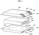
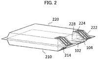
- FIGS. 1 and 2 are schematic perspective views illustrating a secondary battery including a pouch for a secondary battery in accordance with exemplary embodiments.
- FIG. 1 is an exploded perspective view of a secondary battery.
- FIG. 2 is a perspective view illustrating a secondary battery in a sealed state of the pouch for a secondary battery of in FIG. 1 .
- FIGS. 1 and 2 a pouch for a secondary battery and a secondary battery according to embodiments of the present invention will be described together with reference to FIGS. 1 and 2 .
- FIG. 1 for convenience of descriptions, a first pouch cup 210 and a second pouch cup 210 are illustrated as being separated from each other, but the first pouch cup 210 and the second pouch cup 210 may be integrally connected to each other.
- illustration of a battery cell 100 is omitted in FIG. 2 .
- a pouch for a secondary battery may include a first pouch cup 210 and a second pouch cup 220.
- the first pouch cup 210 and the second pouch cup may have substantially the same shape.
- the secondary battery may include the battery cell 100 accommodated in the pouch.
- the battery cell 100 may include an electrode assembly.
- the electrode assembly may include repeatedly stacked electrodes and a separation layer disposed between the electrodes.
- Each of the electrodes may include an active material layer formed on an electrode current collector.
- the electrodes may include an anode and a cathode.
- the electrode current collector may include a cathode current collector included in the cathode and an anode current collector included in the anode.
- the active material layer may include a cathode active material layer included in the cathode and an anode active material layer included in the anode.
- the cathode may include the cathode current collector and the cathode active material layer formed by coating a cathode active material on the cathode current collector.
- the cathode active material may include a compound capable of reversibly intercalating and deintercalating lithium ions.
- the secondary battery may be provided as a lithium secondary battery.
- the cathode active material may include lithium-transition metal composite oxide particles.
- the lithium-transition metal composite oxide contained in the lithium-transition metal composite oxide particles may include a lithium-manganese oxide, a lithium-cobalt-based oxide, a lithium-nickel-based oxide, a lithium-manganese-cobalt-based oxide, etc.
- the lithium-transition metal composite oxide particles may include nickel (Ni), and may further include at least one of cobalt (Co) and manganese (Mn).
- the lithium-transition metal composite oxide particles may be represented by Chemical Formula 1 below.
- Chemical Formula 1 Li x Ni 1-y M y O 2-z X z
- M may represent at least one element selected from Na, Mg, Ca, Y, Ti, Zr, Hf, V, Nb, Ta, Cr, Mo, W, Mn, Co, Fe, Cu, Ag, Zn, B, Al, Ga, C, Si, Sn or Zr.
- X may represent at least one element selected from O, F, S and P.
- a molar ratio (1-y) of nickel in Chemical Formula 1 may be in a range from 0.8 to 0.95.
- power and capacity may be increased using a high-nickel (High-Ni) cathode composition.
- High-Ni high-nickel
- generation of gas due to a side reaction between the cathode active material and an electrolyte may be increased.
- the lithium-transition metal composite oxide particles may be represented by Chemical Formula 2 below, and may have an olivine structure.
- Chemical Formula 2 LiMPO 4
- M may be at least one element selected from Fe, Mn, Ni, Co, and V.
- the cathode current collector may include a metallic material that may not be reactive in a charge/discharge voltage range of the lithium secondary battery, and may be easily coated and adhered to the electrode active material.
- the cathode current collector may include, e.g., stainless steel, nickel, aluminum, titanium, copper, zinc or an alloy thereof, preferably aluminum or an aluminum alloy.
- a slurry may be prepared by mixing and stirring the cathode active material with a binder, a conductive material and/or a dispersive agent in a solvent.
- the slurry may be coated on the cathode current collector, and then dried and pressed to form the cathode including the cathode active material layer
- the binder may include an organic based binder such as a polyvinylidene fluoride-hexafluoropropylene copolymer (PVDF-co-HFP), polyvinylidenefluoride (PVDF), polyacrylonitrile, polymethylmethacrylate, etc., or an aqueous based binder such as styrene-butadiene rubber (SBR) that may be used with a thickener such as carboxymethyl cellulose (CMC).
- organic based binder such as a polyvinylidene fluoride-hexafluoropropylene copolymer (PVDF-co-HFP), polyvinylidenefluoride (PVDF), polyacrylonitrile, polymethylmethacrylate, etc.
- an aqueous based binder such as styrene-butadiene rubber (SBR) that may be used with a thickener such as carboxymethyl cellulose (CMC).
- SBR
- a PVDF-based binder may be used as a cathode binder.
- an amount of the binder for forming the cathode active material layer may be reduced, and an amount of the cathode active material may be relatively increased.
- capacity and power of the secondary battery may be further improved.
- the conductive material may be added to facilitate electron mobility between active material particles.
- the conductive material may include a carbon-based material such as graphite, carbon black, graphene, carbon nanotube, etc., and/or a metal-based material such as tin, tin oxide, titanium oxide, a perovskite material such as LaSrCoO 3 or LaSrMnO 3 , etc.
- the anode may include the anode current collector and the anode active material layer formed by coating the anode active material on the anode current collector.
- the anode active material may include a material commonly used in the related art which may be capable of adsorbing and ejecting lithium ions.
- a carbon-based material such as a crystalline carbon, an amorphous carbon, a carbon complex or a carbon fiber, a lithium alloy, a silicon (Si)-based compound, etc., may be used.
- the amorphous carbon may include a hard carbon, cokes, a mesocarbon microbead (MCMB), a mesophase pitch-based carbon fiber (MPCF), etc.
- MCMB mesocarbon microbead
- MPCF mesophase pitch-based carbon fiber
- the crystalline carbon may include a graphite-based material such as natural graphite, graphitized cokes, graphitized MCMB, graphitized MPCF, etc.
- the lithium alloy may further include aluminum, zinc, bismuth, cadmium, antimony, silicon, lead, tin, gallium, indium, etc.
- the anode active material may include the silicon-based active material to provide a high-capacity lithium secondary battery.
- the silicon-based active material may include SiOx (0 ⁇ x ⁇ 2) or SiOx (0 ⁇ x ⁇ 2) containing a lithium compound.
- SiOx containing the Li compound may be SiOx containing a lithium silicate.
- the lithium silicate may be present in at least a portion of an SiOx (0 ⁇ x ⁇ 2) particle.
- lithium silicate may be present at an inside and/or on a surface of the SiOx (0 ⁇ x ⁇ 2) particle.
- the lithium silicate may include Li 2 SiO 3 , Li 2 Si 2 O 5 , Li 4 SiO 4 , Li 4 Si 3 O 8 , etc.
- the silicon-based active material may include, e.g., a silicon-carbon composite compound such as silicon carbide (SiC).
- the anode current collector may include gold, stainless steel, nickel, aluminum, titanium, copper or an alloy thereof, preferably may include copper or a copper alloy.
- a slurry may be prepared by mixing and stirring the anode active material with a binder, a conductive material and/or a dispersive agent in a solvent.
- the slurry may be coated on the anode current collector, and then dried and pressed to form the anode including the anode active material layer.
- the binder and the conductive material substantially the same as or similar to those used for forming the cathode may be used in the anode.
- the binder for forming the anode may include, e.g., an aqueous binder such as styrene-butadiene rubber (SBR) for compatibility with the carbon-based active material, and may be used together with a thickener such as carboxymethyl cellulose (CMC).
- SBR styrene-butadiene rubber
- CMC carboxymethyl cellulose
- the separation layer may be interposed between the cathode and the anode.
- the separation layer 140 include a porous polymer film prepared from, e.g., a polyolefin-based polymer such as an ethylene homopolymer, a propylene homopolymer, an ethylene/butene copolymer, an ethylene/hexene copolymer, an ethylene/methacrylate copolymer, or the like.
- the separation layer may also include a non-woven fabric formed from a glass fiber with a high melting point, a polyethylene terephthalate fiber, or the like.
- an electrode cell may be defined by the cathode, the anode and the separation layer, and a plurality of the electrode cells may be stacked to form the electrode assembly.
- the battery cell may be accommodated together with an electrolyte in the pouch for a secondary battery according to exemplary embodiments to define the secondary battery.
- a non-aqueous electrolyte may be used as the electrolyte.
- the non-aqueous electrolyte solution may include a lithium salt and an organic solvent.
- the lithium salt may be represented by Li + X - , and an anion of the lithium salt X - may include, e.g., F - , Cl - , Br - , I - , NO 3 - , N(CN) 2 - , BF 4 - , ClO 4 - , PF 6 - , (CF 3 ) 2 PF 4 - , (CF 3 ) 3 PF 3 - , (CF 3 ) 4 PF 2 - , (CF 3 ) 5 PF - , (CF 3 ) 6 P - , CF 3 SO 3 - , CF 3 CF 2 SO 3 - , (CF 3 SO 2 ) 2 N - , (FSO 2 ) 2 N - , CF 3 CF 2 (CF 3 ) 2 CO - , (CF 3 SO 2 ) 2 CH - ,
- the organic solvent may include, e.g., propylene carbonate (PC), ethylene carbonate (EC), diethyl carbonate (DEC), dimethyl carbonate (DMC), ethylmethyl carbonate (EMC), methylpropyl carbonate, dipropyl carbonate, dimethyl sulfoxide, acetonitrile, dimethoxy ethane, diethoxy ethane, vinylene carbonate, sulfolane, gamma-butyrolactone, propylene sulfite, tetrahydrofuran, etc. These may be used alone or in a combination of two or more therefrom.
- PC propylene carbonate
- EC ethylene carbonate
- DEC diethyl carbonate
- DMC dimethyl carbonate
- EMC ethylmethyl carbonate
- methylpropyl carbonate dipropyl carbonate
- dimethyl sulfoxide acetonitrile
- dimethoxy ethane diethoxy
- the electrode current collector may include a notched portion (not illustrated).
- the notched portion may serve as, e.g., an electrode tab.
- the notched portion may include a cathode notched potion protruding from the cathode current collector and an anode notched portion protruding from the anode current collector.
- Electrode leads 102 and 104 may be electrically connected to the notched portions, and may be exposed to an outside of the pouch.
- the electrode leads 102 and 104 may serve as external connection leads for applying a power to the secondary battery.
- the electrode leads may include a cathode lead 102 and an anode lead 104.
- the cathode lead 102 and the anode lead 104 may be disposed at both opposite sides of the secondary battery. In an embodiment, the cathode lead 102 and the anode lead 104 may be fused together at one side of the pouch.
- Each pouch cup of the pouch for a secondary battery may include an inner resin layer and an outer resin layer.
- the inner resin layer may include a polyolefin resin, a copolymer of ethylene and an acrylic acid, a copolymer of propylene and an acrylic acid, etc.
- the polyolefin resin may include unstretched polypropylene, polypropylene-butylene-ethylene terpolymer, polypropylene, a chlorinated polypropylene (CPP) resin, polyethylene, ethylene propylene copolymer, etc.
- the inner resin layer may include a polymer resin having enhanced electrolyte resistance.
- the outer resin layer may have a single-layered structure or a multi-layered structure including, e.g., polyethylene, polypropylene, polyethylene terephthalate, nylon, a low density polyethylene (LDPE), a high density polyethylene (HDPE), a linear low density polyethylene (LLDPE), etc.
- the outer resin layer may be laminated on the inner resin layer to prevent a direct exposure of the inner resin layer.
- Each thickness of the inner resin layer or the outer resin layer may be from 5 ⁇ m to 100 ⁇ m, e.g., from 10 ⁇ m to 80 ⁇ m.
- the pouch for a secondary battery pouch includes a tab receiving portion 218 and 228 communicating with one end of the battery cell accommodating portion 216 and 226, and a supporting portion having a space separated or divided from the tab receiving portion 212 and 222.
- the supporting portion may include two or more first supporting portions 212 and two or more second supporting portions 222.
- a pair of the first supporting portions 212 may be disposed to be spaced apart from each other with the first tab receiving portion 218 interposed therebetween.
- the first supporting portion 212 may be disposed at each of both sides of the first tab receiving portion 218.
- a pair of the second supporting portions 222 may be disposed to be spaced apart from each other with the second tab receiving portion 228 interposed therebetween.
- the second supporting portion 222 may be disposed at each of both sides of the second tab receiving portion 228.
- the first supporting portion 212 and the second supporting portion 222 may face each other in a thickness direction. In exemplary embodiments, at least a portion of a top surface of the first support portion 212 and at least a portion of a bottom surface of the second supporting portion 222 may contact each other.
- the first supporting portion 212 may have a space (e.g., a first space) separated from the first tab receiving portion 218 and the first battery cell accommodating portion 216 by a first inner wall 212b.
- the second supporting portion 222 may have a space (e.g., a second space) separated from the second tab receiving portion 228 and the second battery cell accommodating portion 226 by a second inner wall 222b.
- first supporting portions 212 and the second supporting portions 222 may face each other in the thickness direction.
- the first pouch cup 210 and the second pouch cup 220 may be aligned and coupled with each other so that the first supporting portion 212 and the second supporting portion 222 may contact or face each other.
- the electrode leads 102 and 104 may not be in contact with the first supporting portion 212 and the second supporting portion 222, and may be partially disposed in the tab receiving portion 218 and 228 to protrude to an outside of the pouch.
- the pouch may include one first supporting portion 212 and one second supporting portion 222.
- the first supporting portion 212 may be disposed under the first tab receiving portion 218 so that a top surface of the first supporting portion 212 may contact a bottom surface of at least one of the electrode leads 102 and 104.
- the second supporting portion 222 may be disposed on the second tab receiving portion 228 so that the bottom surface of the second supporting portion 222 may contact a top surface of at least one of the electrode leads 102 and 104.
- the top surface of the first supporting portion 212 may be in contact with the bottom surfaces of the supporting portion 222 and the electrode lead 102 and 104.
- the bottom surface of the second supporting portion 222 may be in contact with the top surfaces of the first supporting portion 212 and the electrode lead 102 and 104.
- the first supporting portion 212 may be disposed at each of a front end portion and a rear end portion in a length direction of the pouch.
- the top surface of the first supporting portion 212 disposed at the front end portion may be in contact with or adjacent to the electrode lead 102 and 104.
- the second supporting portion 222 may be disposed to be symmetrical with the first supporting portion 212 in the thickness direction.
- one of the plurality of the first supporting portions 212 may be in contact with or adjacent to the anode lead 102, and the other one may be in contact with or adjacent to the anode lead 104.
- the second supporting portion 222 may be disposed to be symmetrical with the first supporting portion 212 in the thickness direction.
- the pouch for a secondary battery may include a reinforcing film 214 and 224 attached to an outer wall 212c and 222c of the supporting portion 212 and 222.
- the reinforcing film 214 and 224 may include a different material from that of the outer wall 212c and 222c.
- the outer wall 212c and 222c may be a part of the pouch cup 210 and 220.
- the reinforcing films 214 and 224 may include a first reinforcing film 214 and a second reinforcing film 224 attached on the outer wall 212c of the first supporting portion 212 and the outer wall 222c of the second supporting portion 222, respectively.
- One end of the first reinforcing film 214 may be located on at least a portion of an outer bottom surface of the first battery cell accommodating portion 216, and one end of the second reinforcing film 224 may be located on at least a portion of an outer top surface of the second battery cell accommodating portion 226.
- the reinforcing film 214 and 224 may be provided as a film that may fuse the outer walls 212c and 222c of the supporting portions 212 and 222 and columns 222a (see, e.g., FIG. 3 ) with each other.
- the reinforcing film 214, 224 may include an amorphous polyolefin.
- the amorphous polyolefin may be an amorphous polypropylene.
- the reinforcing film 214 and 224 may be easily adhered to the supporting portions 212 and 222 through a simple process.
- first reinforcing films 214 may be formed on an outer surface of the first pouch cup 210, e.g., the outer wall of the supporting portion 212 to be spaced apart from each other.
- a plurality of the second reinforcing films 224 may be formed on an outer surface of the second pouch cup 220, e.g., the outer wall of the supporting portion 222 to be spaced apart from each other.
- the first reinforcing film 214 and the second reinforcing film 224 may disperse a pressure applied to each of the first supporting portion 212 and the second supporting portion 222 from the inside of the battery cell accommodating portions 216 and 226 in a short axis direction.
- a spacing between the outer wall of the first supporting portion 212 and first columns to be described later or a spacing between the outer wall of the second supporting portion 222 and the second columns 222a may be stably maintained.
- each length of the first reinforcing film 214 and the second reinforcing film 224 may be greater than a length of the outer wall of the first supporting portion 212 or the second supporting portion 222 (e.g., a length of a lateral side of the outer wall).
- the reinforcing film 214 and 224 may extend on the outer surface of the battery cell receiving portions 216 and 226 of the pouch cups 216 and 226, the outer wall of the supporting portions 212 and 222, and an end portion of the pouch cups 210 and 220.
- mechanical stability of the first outer wall 212c may be further increased in a long axis direction by the first reinforcing film 214
- mechanical stability of the second outer wall 222c may be further increased in the long axis direction by the second reinforcing film 224.
- the pressure applied to the first supporting portion 212 and the second supporting portion 222 from the inside of the battery cell accommodating portions 216 and 226, respectively may be dispersed in a stepwise manner until the first supporting portion 212 and the second supporting portion 222 may be completely vented.
- the spacing between the supporting portions 212 and 222 and the pouch cups 210 and 220 may be uniformly induced from a first row of columns to be described later, and a pressure change at the inside of the pouch may be effectively delayed.
- An insulating member (not illustrated) may be wound around a portion of each of the electrode leads 102 and 104 to prevent an electrical short circuit.
- the electrode assembly included in the battery cell 100 is illustrated as a wound type in FIG. 1 , but the electrode assembly may have, e.g., a stacked shape or a folded jelly-roll shape.
- first pouch cup 210 and the second pouch cup 220 may be a single or unitary member integrally connected to each other. In this case, an area of a sealing surface or a bonding surface of the first pouch cup 210 and the second pouch cup 220 may be reduced.
- first pouch cup 210 and the second pouch cup 220 are an integral member, a connecting region of the pouch cups 210 and 220 may be formed at any one side of each pouch cup 210 and 220.
- the first supporting portion 212 and the second supporting portion 222 may be formed of the same material as that of the above-described inner resin layer.
- the supporting portions 212 and 222 may include a polyolefin resin, a copolymer of ethylene and an acrylic acid, a copolymer of propylene and an acrylic acid, etc.
- the polyolefin resin may include unstretched polypropylene, polypropylene-butylene-ethylene terpolymer, polypropylene, a chlorinated polypropylene (CPP) resin, polyethylene, ethylene propylene copolymer, etc.
- CPP chlorinated polypropylene
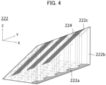
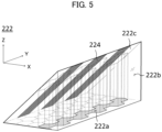
- FIGS. 3 to 5 are schematic perspective views illustrating a second supporting portion in accordance with exemplary embodiments.
- FIGS. 3 to 5 provide perspective views of the second supporting portion, and the first supporting portion may have a structure and a shape substantially the same or similar to those of the second supporting portion
- the second supporting portion 222 may include at least one second column 222a and at least one pressing pattern 222c.
- a plurality of the second columns 222a may be included in the second supporting portion 222, and a bottom surface of each of the second columns 222a may have a polygonal shape.
- the second column 222a may have a hollow structure.
- the second column 222a may have a hexagonal cross-section.
- an external force applied to the second supporting portion 222 may be more easily dispersed or absorbed, and mechanical stability of the pouch may be further improved.
- the second columns 222a may have the same shape.
- the second columns 222a may have different shapes. For example, some of the second columns 222a may have a rectangular cross-section, and others of the second columns 222a may have a triangular cross-section.
- the second columns 222a may form a honeycomb structure. Accordingly, the external force applied to the second supporting portion 222 may be more easily dispersed or absorbed, and mechanical stability of the pouch may be further improved.
- An inner space partitioned by the second column may be a vacuum.
- a through hole may be connected to an outside of the pouch cup, and an inner space of the column may be vacuum-treated. Thereafter, the inner space of the column may be vacuum-treated by sealing the through hole.
- a plurality of the second columns 222a may be arranged in a Y-direction to form a column row, and the plurality of column rows may be arranged along an X-direction.
- a height of the column rows may sequentially decrease as a distance from the battery cell accommodating portion 216 increases.
- the shade-designated second columns 222a may have a 22-gonal cross-section.
- a second column row including the shade-designated second columns 222a may have a 38-gonal cross-section.
- the first column row indicated in FIG. 4 may be in an integral communication with the second battery cell accommodating portion 226 by an action of the second reinforcing film 224
- the second column row indicated in FIG. 5 may also be in an integral communication with the second battery cell accommodating portion 226 by an action of the second reinforcing film 224.
- the communication of the first column row and the communication of the second column row may be sequentially performed. For example, communications from the first column row to the fifth column row illustrated in FIGS. 4 and 5 may be sequentially performed.
- a pressure change at the inside of the pouch may be delayed in a stepwise manner, and life-span stability of the secondary battery may be improved.
Landscapes
- Chemical & Material Sciences (AREA)
- Chemical Kinetics & Catalysis (AREA)
- Electrochemistry (AREA)
- General Chemical & Material Sciences (AREA)
- Engineering & Computer Science (AREA)
- Manufacturing & Machinery (AREA)
- Sealing Battery Cases Or Jackets (AREA)
Applications Claiming Priority (1)
| Application Number | Priority Date | Filing Date | Title |
|---|---|---|---|
| KR1020210112876A KR20230030788A (ko) | 2021-08-26 | 2021-08-26 | 이차 전지용 파우치 및 이를 포함하는 이차 전지 |
Publications (1)
| Publication Number | Publication Date |
|---|---|
| EP4160779A1 true EP4160779A1 (fr) | 2023-04-05 |
Family
ID=83059370
Family Applications (1)
| Application Number | Title | Priority Date | Filing Date |
|---|---|---|---|
| EP22191980.6A Pending EP4160779A1 (fr) | 2021-08-26 | 2022-08-24 | Poche pour batterie secondaire et batterie secondaire la comprenant |
Country Status (3)
| Country | Link |
|---|---|
| US (1) | US20230066639A1 (fr) |
| EP (1) | EP4160779A1 (fr) |
| KR (1) | KR20230030788A (fr) |
Citations (3)
| Publication number | Priority date | Publication date | Assignee | Title |
|---|---|---|---|---|
| EP1202371A1 (fr) * | 1999-03-26 | 2002-05-02 | Matsushita Electric Industrial Co., Ltd. | Batterie stratifiee de type gaine |
| US20090197160A1 (en) * | 2008-01-31 | 2009-08-06 | Sanyo Electric Co., Ltd. | Stack type battery |
| US20140154554A1 (en) * | 2011-08-24 | 2014-06-05 | Sk Innovation Co.,Ltd. | Battery module |
Family Cites Families (1)
| Publication number | Priority date | Publication date | Assignee | Title |
|---|---|---|---|---|
| KR102264734B1 (ko) | 2017-09-15 | 2021-06-15 | 주식회사 엘지에너지솔루션 | 비수성 전해액 및 이를 포함하는 리튬 이차전지 |
-
2021
- 2021-08-26 KR KR1020210112876A patent/KR20230030788A/ko active Search and Examination
-
2022
- 2022-08-24 EP EP22191980.6A patent/EP4160779A1/fr active Pending
- 2022-08-25 US US17/896,064 patent/US20230066639A1/en active Pending
Patent Citations (3)
| Publication number | Priority date | Publication date | Assignee | Title |
|---|---|---|---|---|
| EP1202371A1 (fr) * | 1999-03-26 | 2002-05-02 | Matsushita Electric Industrial Co., Ltd. | Batterie stratifiee de type gaine |
| US20090197160A1 (en) * | 2008-01-31 | 2009-08-06 | Sanyo Electric Co., Ltd. | Stack type battery |
| US20140154554A1 (en) * | 2011-08-24 | 2014-06-05 | Sk Innovation Co.,Ltd. | Battery module |
Also Published As
| Publication number | Publication date |
|---|---|
| US20230066639A1 (en) | 2023-03-02 |
| KR20230030788A (ko) | 2023-03-07 |
Similar Documents
| Publication | Publication Date | Title |
|---|---|---|
| KR101829528B1 (ko) | 전극, 비수전해질 전지 및 전지 팩 | |
| US10461314B2 (en) | Nonaqueous electrolyte battery and battery pack | |
| CN113193225A (zh) | 锂二次电池 | |
| US20230163283A1 (en) | Anode for lithium secondary battery, method of fabricating the same and lithium secondary battery including the same | |
| KR20220169381A (ko) | 파우치형 이차 전지용 벤트 기구 및 이를 포함하는 배터리 모듈 | |
| US11916225B2 (en) | Lithium secondary battery | |
| US20230163277A1 (en) | Anode for lithium secondary battery and lithium secondary battery including the same | |
| KR20220012024A (ko) | 리튬 이차 전지 | |
| EP4106085A1 (fr) | Dispositif de ventilation pour batterie secondaire de type à sachet et module de batterie l'incluant | |
| US20220263076A1 (en) | Anode for Secondary Battery and Lithium Secondary Battery Including the Same | |
| EP4160779A1 (fr) | Poche pour batterie secondaire et batterie secondaire la comprenant | |
| US20230062950A1 (en) | Pouch for secondary battery and secondary battery comprising the same | |
| EP4106081A1 (fr) | Dispositif de ventilation pour batterie secondaire de type à sachet et module de batterie le comprenant | |
| US20240021926A1 (en) | Secondary Battery | |
| US12009491B2 (en) | Lithium secondary battery | |
| US20220367858A1 (en) | Electrode Structure and Lithium Secondary Battery Including the Same | |
| US20240021800A1 (en) | Lithium secondary battery | |
| US20230111027A1 (en) | Lithium secondary battery and battery system including the same | |
| US20230387396A1 (en) | Anode for secondary battery, method of fabricating the same and lithium secondary battery including the same | |
| US20240178366A1 (en) | Cathode for Lithium Secondary Battery and Lithium Secondary Battery Including the Same | |
| US20240186485A1 (en) | Anode for lithium secondary battery and lithium secondary battery including the same | |
| KR20240024617A (ko) | 표시 패널 일체형 리튬 이차 전지 | |
| CN116565133A (zh) | 锂二次电池用正极及包括该正极的锂二次电池 | |
| US20140045047A1 (en) | Nonaqueous electrolyte secondary battery | |
| KR20220059591A (ko) | 이차 전지 |
Legal Events
| Date | Code | Title | Description |
|---|---|---|---|
| PUAI | Public reference made under article 153(3) epc to a published international application that has entered the european phase |
Free format text: ORIGINAL CODE: 0009012 |
|
| STAA | Information on the status of an ep patent application or granted ep patent |
Free format text: STATUS: REQUEST FOR EXAMINATION WAS MADE |
|
| 17P | Request for examination filed |
Effective date: 20220824 |
|
| AK | Designated contracting states |
Kind code of ref document: A1 Designated state(s): AL AT BE BG CH CY CZ DE DK EE ES FI FR GB GR HR HU IE IS IT LI LT LU LV MC MK MT NL NO PL PT RO RS SE SI SK SM TR |
|
| P01 | Opt-out of the competence of the unified patent court (upc) registered |
Effective date: 20230602 |