EP4160722A1 - Electrode sheet and lithium-ion battery - Google Patents
Electrode sheet and lithium-ion battery Download PDFInfo
- Publication number
- EP4160722A1 EP4160722A1 EP21914620.6A EP21914620A EP4160722A1 EP 4160722 A1 EP4160722 A1 EP 4160722A1 EP 21914620 A EP21914620 A EP 21914620A EP 4160722 A1 EP4160722 A1 EP 4160722A1
- Authority
- EP
- European Patent Office
- Prior art keywords
- electrode sheet
- groove
- active layer
- current collector
- lithium
- Prior art date
- Legal status (The legal status is an assumption and is not a legal conclusion. Google has not performed a legal analysis and makes no representation as to the accuracy of the status listed.)
- Pending
Links
Images

Classifications
-
- H—ELECTRICITY
- H01—ELECTRIC ELEMENTS
- H01M—PROCESSES OR MEANS, e.g. BATTERIES, FOR THE DIRECT CONVERSION OF CHEMICAL ENERGY INTO ELECTRICAL ENERGY
- H01M4/00—Electrodes
- H01M4/02—Electrodes composed of, or comprising, active material
- H01M4/13—Electrodes for accumulators with non-aqueous electrolyte, e.g. for lithium-accumulators; Processes of manufacture thereof
-
- H—ELECTRICITY
- H01—ELECTRIC ELEMENTS
- H01M—PROCESSES OR MEANS, e.g. BATTERIES, FOR THE DIRECT CONVERSION OF CHEMICAL ENERGY INTO ELECTRICAL ENERGY
- H01M4/00—Electrodes
- H01M4/02—Electrodes composed of, or comprising, active material
- H01M4/36—Selection of substances as active materials, active masses, active liquids
- H01M4/362—Composites
- H01M4/366—Composites as layered products
-
- H—ELECTRICITY
- H01—ELECTRIC ELEMENTS
- H01M—PROCESSES OR MEANS, e.g. BATTERIES, FOR THE DIRECT CONVERSION OF CHEMICAL ENERGY INTO ELECTRICAL ENERGY
- H01M10/00—Secondary cells; Manufacture thereof
- H01M10/05—Accumulators with non-aqueous electrolyte
- H01M10/052—Li-accumulators
-
- H—ELECTRICITY
- H01—ELECTRIC ELEMENTS
- H01M—PROCESSES OR MEANS, e.g. BATTERIES, FOR THE DIRECT CONVERSION OF CHEMICAL ENERGY INTO ELECTRICAL ENERGY
- H01M10/00—Secondary cells; Manufacture thereof
- H01M10/05—Accumulators with non-aqueous electrolyte
- H01M10/052—Li-accumulators
- H01M10/0525—Rocking-chair batteries, i.e. batteries with lithium insertion or intercalation in both electrodes; Lithium-ion batteries
-
- H—ELECTRICITY
- H01—ELECTRIC ELEMENTS
- H01M—PROCESSES OR MEANS, e.g. BATTERIES, FOR THE DIRECT CONVERSION OF CHEMICAL ENERGY INTO ELECTRICAL ENERGY
- H01M4/00—Electrodes
- H01M4/02—Electrodes composed of, or comprising, active material
- H01M4/04—Processes of manufacture in general
- H01M4/0402—Methods of deposition of the material
- H01M4/0404—Methods of deposition of the material by coating on electrode collectors
-
- H—ELECTRICITY
- H01—ELECTRIC ELEMENTS
- H01M—PROCESSES OR MEANS, e.g. BATTERIES, FOR THE DIRECT CONVERSION OF CHEMICAL ENERGY INTO ELECTRICAL ENERGY
- H01M4/00—Electrodes
- H01M4/02—Electrodes composed of, or comprising, active material
- H01M4/13—Electrodes for accumulators with non-aqueous electrolyte, e.g. for lithium-accumulators; Processes of manufacture thereof
- H01M4/133—Electrodes based on carbonaceous material, e.g. graphite-intercalation compounds or CFx
-
- H—ELECTRICITY
- H01—ELECTRIC ELEMENTS
- H01M—PROCESSES OR MEANS, e.g. BATTERIES, FOR THE DIRECT CONVERSION OF CHEMICAL ENERGY INTO ELECTRICAL ENERGY
- H01M4/00—Electrodes
- H01M4/02—Electrodes composed of, or comprising, active material
- H01M4/64—Carriers or collectors
-
- H—ELECTRICITY
- H01—ELECTRIC ELEMENTS
- H01M—PROCESSES OR MEANS, e.g. BATTERIES, FOR THE DIRECT CONVERSION OF CHEMICAL ENERGY INTO ELECTRICAL ENERGY
- H01M4/00—Electrodes
- H01M4/02—Electrodes composed of, or comprising, active material
- H01M4/64—Carriers or collectors
- H01M4/66—Selection of materials
- H01M4/661—Metal or alloys, e.g. alloy coatings
-
- H—ELECTRICITY
- H01—ELECTRIC ELEMENTS
- H01M—PROCESSES OR MEANS, e.g. BATTERIES, FOR THE DIRECT CONVERSION OF CHEMICAL ENERGY INTO ELECTRICAL ENERGY
- H01M4/00—Electrodes
- H01M4/02—Electrodes composed of, or comprising, active material
- H01M4/64—Carriers or collectors
- H01M4/70—Carriers or collectors characterised by shape or form
-
- H—ELECTRICITY
- H01—ELECTRIC ELEMENTS
- H01M—PROCESSES OR MEANS, e.g. BATTERIES, FOR THE DIRECT CONVERSION OF CHEMICAL ENERGY INTO ELECTRICAL ENERGY
- H01M50/00—Constructional details or processes of manufacture of the non-active parts of electrochemical cells other than fuel cells, e.g. hybrid cells
- H01M50/50—Current conducting connections for cells or batteries
- H01M50/531—Electrode connections inside a battery casing
- H01M50/533—Electrode connections inside a battery casing characterised by the shape of the leads or tabs
-
- H—ELECTRICITY
- H01—ELECTRIC ELEMENTS
- H01M—PROCESSES OR MEANS, e.g. BATTERIES, FOR THE DIRECT CONVERSION OF CHEMICAL ENERGY INTO ELECTRICAL ENERGY
- H01M50/00—Constructional details or processes of manufacture of the non-active parts of electrochemical cells other than fuel cells, e.g. hybrid cells
- H01M50/50—Current conducting connections for cells or batteries
- H01M50/531—Electrode connections inside a battery casing
- H01M50/534—Electrode connections inside a battery casing characterised by the material of the leads or tabs
-
- H—ELECTRICITY
- H01—ELECTRIC ELEMENTS
- H01M—PROCESSES OR MEANS, e.g. BATTERIES, FOR THE DIRECT CONVERSION OF CHEMICAL ENERGY INTO ELECTRICAL ENERGY
- H01M50/00—Constructional details or processes of manufacture of the non-active parts of electrochemical cells other than fuel cells, e.g. hybrid cells
- H01M50/50—Current conducting connections for cells or batteries
- H01M50/531—Electrode connections inside a battery casing
- H01M50/536—Electrode connections inside a battery casing characterised by the method of fixing the leads to the electrodes, e.g. by welding
-
- H—ELECTRICITY
- H01—ELECTRIC ELEMENTS
- H01M—PROCESSES OR MEANS, e.g. BATTERIES, FOR THE DIRECT CONVERSION OF CHEMICAL ENERGY INTO ELECTRICAL ENERGY
- H01M10/00—Secondary cells; Manufacture thereof
- H01M10/05—Accumulators with non-aqueous electrolyte
- H01M10/058—Construction or manufacture
- H01M10/0585—Construction or manufacture of accumulators having only flat construction elements, i.e. flat positive electrodes, flat negative electrodes and flat separators
-
- H—ELECTRICITY
- H01—ELECTRIC ELEMENTS
- H01M—PROCESSES OR MEANS, e.g. BATTERIES, FOR THE DIRECT CONVERSION OF CHEMICAL ENERGY INTO ELECTRICAL ENERGY
- H01M4/00—Electrodes
- H01M4/02—Electrodes composed of, or comprising, active material
- H01M2004/021—Physical characteristics, e.g. porosity, surface area
-
- H—ELECTRICITY
- H01—ELECTRIC ELEMENTS
- H01M—PROCESSES OR MEANS, e.g. BATTERIES, FOR THE DIRECT CONVERSION OF CHEMICAL ENERGY INTO ELECTRICAL ENERGY
- H01M4/00—Electrodes
- H01M4/02—Electrodes composed of, or comprising, active material
- H01M2004/026—Electrodes composed of, or comprising, active material characterised by the polarity
- H01M2004/027—Negative electrodes
-
- Y—GENERAL TAGGING OF NEW TECHNOLOGICAL DEVELOPMENTS; GENERAL TAGGING OF CROSS-SECTIONAL TECHNOLOGIES SPANNING OVER SEVERAL SECTIONS OF THE IPC; TECHNICAL SUBJECTS COVERED BY FORMER USPC CROSS-REFERENCE ART COLLECTIONS [XRACs] AND DIGESTS
- Y02—TECHNOLOGIES OR APPLICATIONS FOR MITIGATION OR ADAPTATION AGAINST CLIMATE CHANGE
- Y02E—REDUCTION OF GREENHOUSE GAS [GHG] EMISSIONS, RELATED TO ENERGY GENERATION, TRANSMISSION OR DISTRIBUTION
- Y02E60/00—Enabling technologies; Technologies with a potential or indirect contribution to GHG emissions mitigation
- Y02E60/10—Energy storage using batteries
Definitions
- the present invention relates to an electrode sheet and a lithium-ion battery, and, to the technical field of lithium-ion batteries.
- the impedance of the lithium-ion battery may be reduced by adjusting the connection position of the tab on the electrode sheet from the edge to the center part of the side, thereby increasing the charging speed of the lithium-ion battery.
- the present invention provides an electrode sheet for improving the cycle performance of a lithium-ion battery under the condition of high-rate charging.
- a first aspect of the present invention provides an electrode sheet, including a current collector, and a first active layer and a second active layer which are sequentially stacked on a surface of the current collector;
- a length of the second groove is greater than a length of the first groove.
- a width of the second groove is the same as a width of the current collector.
- a difference between the length of the second groove and the length of the first groove is less than or equal to 500mm.
- the electrode sheet is a negative electrode sheet, and an average particle size of a negative active material in the second active layer is 10-18 ⁇ m, and a graphitization degree of the negative active material in the second active layer is 86-94%.
- an average particle size and a graphitization degree of a negative active material in the first active layer are greater than the average particle size and the graphitization degree of the negative active material in the second active layer, respectively.
- an area of the vertical projection of the first groove on the current collector is greater than an area of a tab connection region of the current collector.
- a width of the first groove is 1-2 times a width of the tab connection region.
- the length of the first groove is 1-2 times a length of the tab connection region.
- a second aspect of the present invention provides a lithium-ion battery including any of the above electrode sheets.
- the implementation of the present invention has at least the following advantages.
- a first aspect of the present invention provides an electrode sheet, including a current collector, and a first active layer and a second active layer which are sequentially stacked on the surface of the current collector;
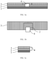
- FIG. 1a is a front view of an electrode sheet according to an embodiment of the present invention
- FIG. 1b is a top view of an electrode sheet according to an embodiment of the present invention
- FIG. 1c is a left view of an electrode sheet according to an embodiment of the present invention.
- the electrode sheet includes a current collector 1, a first active layer 2 disposed on the upper surface of the current collector 1, and a second active layer 3 disposed on the side face of the first active layer 2 far away from an upper surface of the current collector 1.
- a first groove is disposed in the middle of the side face of the first active layer 2, and the second groove is disposed in the second active layer 3.
- the tab 4 is disposed at the first groove and is electrically connected with the current collector 1 (a vertical projection of the tab on the current collector 1 is overlapped with a vertical projection of the first groove on the current collector), and a vertical projection of the second groove on the current collector covers a vertical projection of the first groove on the current collector, so that the thickness of the active layer in a region around the tab is lower than that in a region far away from the tab.
- the length definition of the electrode sheet of the present application is the same as that of an electrode sheet in the art, that is, the longest side of electrode sheet means the length of the electrode sheet, the shortest side of the electrode sheet means a height of the electrode sheet, and a side between the longest side and the shortest side means a width of the electrode sheet.
- a longer side of the electrode sheet means the length of the electrode sheet and a shorter side of the electrode sheet means the height of the electrode sheet; and in FIG. 1b , a shorter side of the electrode sheet means the width of the electrode sheet, therefore, a value of a long side of the electrode sheet is the length of the electrode sheet, a value of a high side of the electrode sheet is the thickness of the electrode sheet, and a value of a wide side of the electrode sheet is the width of the electrode sheet.
- the first groove and the second groove have the same directions of length, width and thickness with the electrode sheet.
- the width of the second groove may be enlarged to make it the same as the width of the current collector, so that the second active layer provided with the second groove can be obtained by skip-coating using the existing coating equipment.
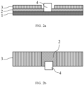
- FIG. 2a is a front view of an electrode sheet according to another embodiment of the present invention
- FIG. 2b is a top view of an electrode sheet according to another embodiment of the present invention.
- the electrode sheet includes a current collector 1, and a first active layer 2 and a second active layer 3 which are sequentially disposed on the surface of the current collector 1.
- a first groove is disposed in the middle of a side surface of the first active layer 1, and the first groove is connected to a tab 4 in a corresponding region of the current collector 1.
- the second active layer 2 is provided with a second groove, and the width of the second groove is the same as the width of the current collector 1. That is, the second active layer is divided into two independent parts, i.e., a left part and a right part, by the second groove.
- a length of the second groove is greater than that of the first groove. And, it is found from the research on the lengths of the first groove and the second groove that the cycle performance of the lithium-ion battery is gradually improved with the continuous increase of the length of the second groove. In order to give consideration to both the energy density and cycle performance of the lithium ion battery, the difference between the length of the second groove and the length of the first groove is less than or equal to 500mm.
- the length and width of the first groove are specifically determined according to the tab, and those skilled in the art can determine the length and width of the first groove according to the actual design and needs of the electrode sheet.
- an average particle size of a negative active material in the second active layer is 10-18 ⁇ m, and a graphitization degree of the negative active material in the second active layer is 86-94%.
- the negative active material in the first active layer is selected from conventional graphite. Specifically, the average particle size and the graphitization degree of the negative active material in the first active layer are greater than the average particle size and the graphitization degree of the negative active material in the second active layer, respectively.
- the average particle size of the negative active material in the second active layer is 10-18 ⁇ m and the graphitization degree of the negative active material in the second active layer is 86-94%
- the average particle size of the negative active material in the first active layer is 12-30 ⁇ m and the graphitization degree of the negative active material in the first active layer is 90-98%.
- a first negative active layer slurry may be prepared by combing the negative active material with a binder, a conductive agent and a thickening agent, and the prepared slurry is coated on the surface of the current collector to obtain the first active layer; and then, a second negative active layer slurry is prepared and the prepared second negative active layer slurry is coated on a surface of the first active layer far away from the current collector, and during the coating process, a region corresponding to the second groove needs to be subjected to blank coating, thereby obtaining the second active layer including the second groove; and finally, the middle region of a side surface of the first active layer is cleaned to obtain a first groove, and a tab is disposed in the first groove to obtain the negative electrode sheet.
- the negative active material may include at least one of artificial graphite, natural graphite and modified graphite;
- the binder may include at least one of polyvinylidene fluoride (PVDF), a copolymer of vinylidene fluoride-hexafluoropropylene, polyamide, polyacrylonitrile, polyacrylate, polyacrylic acid, polyacrylate, polyvinyl pyrrolidone, polyvinyl ether, polymethyl methacrylate, polytetrafluoroethylene, polyhexafluoropropylene, and styrene-butadiene rubber (SBR);
- the conductive agent may include at least one of conductive carbon black, carbon nanotube, conductive graphite, and graphene; and the thickening agent may include sodium carboxymethyl cellulose.
- the electrode sheet provided by the present invention is also applicable to a positive electrode sheet, and the specific preparation method may refer to the preparation of negative electrode sheet except for different materials.
- the current collector may be an aluminum foil
- a positive active material for the positive electrode sheet includes at least one of lithium cobalt oxide, lithium manganese oxide, lithium nickel oxide, lithium nickel cobalt manganese oxide, lithium iron phosphate, lithium manganese iron phosphate, lithium vanadium phosphate, lithium oxyvanadium phosphate, lithium-rich manganese-based material and lithium nickel cobalt aluminate.
- an area of the vertical projection of the first groove on the current collector may be greater than that of a tab connection region in the current collector.
- FIG. 3 is a top view of an electrode sheet according to yet another embodiment of the present invention. As shown in FIG. 3 , the area of the vertical projection of the first groove on the current collector is greater than that of the tab connection region in the current collector.
- the width of the first groove is 1-2 times the width of the tab connection region.
- the length of the first groove is 1-2 times the length of the tab connection region.
- the present invention provides an electrode sheet, which effectively improves the charging risk at the tab connection position by reducing the thickness of the active layer around the tab, thereby improving the cycle retention rate of the lithium-ion battery under the condition of maintaining high-rate charging.
- a second aspect of the present invention provides a lithium-ion battery including any of the above electrode sheets.
- the present invention provides a lithium-ion battery, which is prepared by combining the prior art on the basis of the electrode sheet provided by the present invention.
- the lithium-ion battery provided by the present invention has better cycle performance under the condition of high-rate charging.
- FIG. 2a The front view, top view, and left view of the electrode sheet provided by this Example are as shown in FIG. 2a , FIG. 3 , and FIG. 1c , respectively, where:
- the first active layer and the second active layer each included 97 parts by mass of lithium cobalt oxide, 1.5 parts by mass of PVDF and 1.5 parts by mass of carbon black conductive agent 1.5%.
- both the first active layer and the second active layer included 97 parts by mass of graphite, 0.7 parts by mass of carbon black, 1.3 parts by mass of styrene-butadiene rubber and 1 part by mass of sodium carboxymethyl cellulose.
- the average particle size of the negative active material in the first active layer was 18 ⁇ m, and the graphitization degree of the negative active material in the first active layer was 96%; and the average particle size of the negative active material in the second active layer was 15 ⁇ m, and the graphitization degree of the negative active material in the second active layer was 92%.
- FIG. 2a The front view, top view, and left view of the electrode sheet provided by this Example are as shown in FIG. 2a , FIG. 3 , and FIG. 1c , respectively, where:
- the materials of the first active layer and the second active layer were the same as those of Example 1.
- FIG. 2a The front view, top view, and left view of the electrode sheet provided by this Example are as shown in FIG. 2a , FIG. 3 , and FIG. 1c , respectively, where:
- the materials of the first active layer and the second active layer were the same as those of Example 1.
- FIG. 2a The front view, top view, and left view of the electrode sheet provided by this Example are as shown respectively in FIG. 2a , FIG. 3 , and FIG. 1c , respectively, where:
- the materials of the first active layer and the second active layer were the same as those of Example 1.
- FIG. 2a The front view, top view, and left view of the electrode sheet provided by this Example are as shown in FIG. 2a , FIG. 3 , and FIG. 1c , respectively, where:
- the materials of the first active layer and the second active layer were the same as those of Example 1.
- FIG. 2a The front view, top view, and left view of the electrode sheet provided by this Example are as shown in FIG. 2a , FIG. 3 , and FIG. 1c , respectively, where:
- the materials of the first active layer and the second active layer may refer to those of Example 1, except that the average particle size of the negative active material in the second active layer was 15 ⁇ m, and the graphitization degree of the negative active material in the second active layer was 94%.
- FIG. 2a The front view, top view, and left view of the electrode sheet provided by this Example are as shown in FIG. 2a , FIG. 3 , and FIG. 1c , respectively, where:
- the materials of the first active layer and the second active layer may refer to those of Example 1, except that the average particle size of the negative active material in the second active layer was 15 ⁇ m, and the graphitization degree of the negative active material in the second active layer was 90%.
- FIG. 2a The front view, top view, and left view of the electrode sheet provided by this Example are as shown in FIG. 2a , FIG. 3 , and FIG. 1c , respectively, where:
- the materials of the first active layer and the second active layer may refer to those of Example 1, except that the average particle size of the negative active material in the second active layer was 10 ⁇ m, and the graphitization degree of the negative active material in the second active layer was 90%.
- the electrode sheet provided by this Comparative Example included a current collector, a first active layer and a second active layer, and grooves were disposed in the middle of the side surfaces of the first active layer and of the second active layer, where,
- the materials of the first active layer and the second active layer were the same as those of Example 1.
- Lithium-ion batteries were prepared by combining the positive electrode sheet and the negative electrode sheet provided by the Examples 1-8 and the Comparative Example 1 with a separator and an electrolyte, and the cycle capacity retention rate of the lithium-ion batteries was tested.
- the positive active material was purchased from Xiamen Tungsten New Energy Materials Co., Ltd. and the negative active material was purchased from Shanghai Shanshan Technology Co., Ltd.; the separator was purchased from Dongguan Zhuogao Electronic Technology Co., Ltd.; and the electrolyte was purchased from Shenzhen Xinzhoubang Technology Co., Ltd.
- the method for testing the performance of the lithium-ion battery was as follows:
- Example 1-8 and Comparative Example 1 were subjected to 2C/0.7C charge-discharge cycle test at 25°C, and the cycle retention rate (%) was calculated after 500 cycles. The test results were shown in Table 1. Table 1 Test Results of the Performance of Lithium-Ion Batteries Provided by Examples 1-8 and Comparative Example 1 Cycle retention rate at 25°C Example 1 84.8% Example 2 85.5% Example 3 86.1% Example 4 87.2% Example 5 88.1% Example 6 83.9% Example 7 85.8% Example 8 86.7% Comparative Example 1 82.5%
- the lithium-ion batteries provided in Examples 1-8 all had better cycle capacity retention rate; according to the data provided in Examples 1-5, as the length of the second groove increased, the cycle performance of the lithium-ion battery was improved accordingly; according to the data provided in Examples 6-8, the cycle retention rate of the lithium-ion battery increased as the graphitization degree and the average particle size of the active material in the second active layer decreased.
- the lithium ion-battery provided by the present invention had better cycle performance under the condition of high-rate charging.
Landscapes
- Chemical & Material Sciences (AREA)
- Chemical Kinetics & Catalysis (AREA)
- Electrochemistry (AREA)
- General Chemical & Material Sciences (AREA)
- Engineering & Computer Science (AREA)
- Materials Engineering (AREA)
- Manufacturing & Machinery (AREA)
- Composite Materials (AREA)
- Battery Electrode And Active Subsutance (AREA)
- Secondary Cells (AREA)
- Connection Of Batteries Or Terminals (AREA)
Abstract
Description
- The present application claims priority to
Chinese Patent Application No. 202011631163.1, entitled with "ELECTRODE SHEET AND LITHIUM-ION BATTERY", filed with China National Intellectual Property Administration on December 30, 2020 - The present invention relates to an electrode sheet and a lithium-ion battery, and, to the technical field of lithium-ion batteries.
- With the continuous development of 5G era, the status of lithium-ion batteries is becoming more and more important, which also promotes the unceasing development of lithium-ion batteries towards the direction of high power density and high-rate charging. At present, the impedance of the lithium-ion battery may be reduced by adjusting the connection position of the tab on the electrode sheet from the edge to the center part of the side, thereby increasing the charging speed of the lithium-ion battery.
- However, when the position of the tab changes, the current density around the tab will increase, and along with the cycling of the lithium-ion battery, lithium ions will be precipitated, resulting in the deterioration of the cycle performance of the lithium-ion battery. Therefore, how to improve the cycle performance of lithium-ion batteries while maintaining high-rate charging has attracted more and more attention.
- The present invention provides an electrode sheet for improving the cycle performance of a lithium-ion battery under the condition of high-rate charging.
- A first aspect of the present invention provides an electrode sheet, including a current collector, and a first active layer and a second active layer which are sequentially stacked on a surface of the current collector;
- where, the first active layer is provided with a first groove, the second active layer is provided with a second groove, and a vertical projection of the second groove on the current collector covers a vertical projection of the first groove on the current collector;
- a tab is disposed at the first groove and is electrically connected with the current collector.
- Further, a length of the second groove is greater than a length of the first groove.
- Further, a width of the second groove is the same as a width of the current collector.
- Further, a difference between the length of the second groove and the length of the first groove is less than or equal to 500mm.
- Further, the electrode sheet is a negative electrode sheet, and an average particle size of a negative active material in the second active layer is 10-18µm, and a graphitization degree of the negative active material in the second active layer is 86-94%.
- Further, an average particle size and a graphitization degree of a negative active material in the first active layer are greater than the average particle size and the graphitization degree of the negative active material in the second active layer, respectively.
- Incoming591-2023.01.02-PCTEntry-APP-TranslationFurther, an area of the vertical projection of the first groove on the current collector is greater than an area of a tab connection region of the current collector.
- Further, a width of the first groove is 1-2 times a width of the tab connection region.
- Further, the length of the first groove is 1-2 times a length of the tab connection region.
- A second aspect of the present invention provides a lithium-ion battery including any of the above electrode sheets.
- The implementation of the present invention has at least the following advantages.
- 1. The present invention provides an electrode sheet, which effectively improves the charging risk at the connection position of a tab by reducing the thickness of the active layer around the tab, thereby improving the cycle retention rate of the lithium-ion battery under the condition of maintaining high-rate charging.
- 2. The lithium-ion battery provided by the present invention has better cycle performance under the condition of high-rate charging.
- To describe the technical solutions in embodiments of the present invention or in the prior art more clearly, the following briefly explains the accompanying drawings required for describing the embodiments or the prior art. Apparently, the accompanying drawings in the following description are merely some embodiments of the present invention, and persons of ordinary skill in the art may still derive other drawings from these accompanying drawings without creative effort.
-
FIG. 1a is a front view of an electrode sheet according to an embodiment of the present invention. -
FIG. 1b is a top view of an electrode sheet according to an embodiment of the present invention. -
FIG. 1c is a left view of an electrode sheet according to an embodiment of the present invention. -
FIG. 2a is a front view of an electrode sheet according to another embodiment of the present invention. -
FIG. 2b is a top view of an electrode sheet according to another embodiment of the present invention. -
FIG. 3 is a top view of an electrode sheet according to yet another embodiment of the present invention. - Description of reference numerals:
- 1: current collector;
- 2: first active layer;
- 3: second active layer;
- 4: tab.
- To make the objectives, technical solutions, and advantages of the present invention clearer, the technical solutions in embodiments of the present invention will be described clearly and comprehensively below with reference to the embodiments of the present invention. Apparently, the described embodiments are merely a part rather than all embodiments of the present invention. All other embodiments obtained by persons of ordinary skill in the art based on embodiments of the present invention without creative effort shall fall within the protection scope of the present invention.
- A first aspect of the present invention provides an electrode sheet, including a current collector, and a first active layer and a second active layer which are sequentially stacked on the surface of the current collector;
- where, the first active layer is provided with a first groove, the second active layer is provided with a second groove, and the vertical projection of the second groove on the current collector covers the vertical projection of the first groove on the current collector;
- a tab is disposed at the first groove and is electrically connected with the current collector.
- According to the design of existing electrode sheets, side faces of the first active layer and the second active layer are respectively provided with grooves, each groove communicating with an upper surface of the second active layer and an upper surface of the current collector, so that the tab may be disposed at the groove and is electrically connected with the current collector exposed at the groove. The electrode sheet provided in the present invention improves the charging risk of the tab connection position mainly due to reduced thickness of the active layer around the tab. Specifically,
FIG. 1a is a front view of an electrode sheet according to an embodiment of the present invention;FIG. 1b is a top view of an electrode sheet according to an embodiment of the present invention;FIG. 1c is a left view of an electrode sheet according to an embodiment of the present invention. As shown inFIGS. 1a-1c , the electrode sheet includes acurrent collector 1, a firstactive layer 2 disposed on the upper surface of thecurrent collector 1, and a secondactive layer 3 disposed on the side face of the firstactive layer 2 far away from an upper surface of thecurrent collector 1. A first groove is disposed in the middle of the side face of the firstactive layer 2, and the second groove is disposed in the secondactive layer 3. Thetab 4 is disposed at the first groove and is electrically connected with the current collector 1 (a vertical projection of the tab on thecurrent collector 1 is overlapped with a vertical projection of the first groove on the current collector), and a vertical projection of the second groove on the current collector covers a vertical projection of the first groove on the current collector, so that the thickness of the active layer in a region around the tab is lower than that in a region far away from the tab. Where, the length definition of the electrode sheet of the present application is the same as that of an electrode sheet in the art, that is, the longest side of electrode sheet means the length of the electrode sheet, the shortest side of the electrode sheet means a height of the electrode sheet, and a side between the longest side and the shortest side means a width of the electrode sheet. That is, inFIG. 1a , a longer side of the electrode sheet means the length of the electrode sheet and a shorter side of the electrode sheet means the height of the electrode sheet; and inFIG. 1b , a shorter side of the electrode sheet means the width of the electrode sheet, therefore, a value of a long side of the electrode sheet is the length of the electrode sheet, a value of a high side of the electrode sheet is the thickness of the electrode sheet, and a value of a wide side of the electrode sheet is the width of the electrode sheet. And, the first groove and the second groove have the same directions of length, width and thickness with the electrode sheet. The present invention provides an electrode sheet, which effectively improves the charging risk at the connection position of tab by reducing the thickness of the active layer around the tab, thereby improving the cycle retention rate of the lithium-ion battery under the condition of maintaining high-rate charging. - In the electrode sheet structures shown in
FIGS. 1a-1c , since the second active layer is provided with the second groove, in the actual preparation process, the position of the second groove needs to be subjected to blank coating. But the existing coating equipment and coating process cannot directly realize such a coating pattern, therefore, in order to improve the preparation efficiency of the second active layer, the width of the second groove may be enlarged to make it the same as the width of the current collector, so that the second active layer provided with the second groove can be obtained by skip-coating using the existing coating equipment. -
FIG. 2a is a front view of an electrode sheet according to another embodiment of the present invention;FIG. 2b is a top view of an electrode sheet according to another embodiment of the present invention. As shown inFIGS. 2a-2b , the electrode sheet includes acurrent collector 1, and a firstactive layer 2 and a secondactive layer 3 which are sequentially disposed on the surface of thecurrent collector 1. A first groove is disposed in the middle of a side surface of the firstactive layer 1, and the first groove is connected to atab 4 in a corresponding region of thecurrent collector 1. The secondactive layer 2 is provided with a second groove, and the width of the second groove is the same as the width of thecurrent collector 1. That is, the second active layer is divided into two independent parts, i.e., a left part and a right part, by the second groove. - In order to further improve the cycle performance of the lithium-ion battery, a length of the second groove is greater than that of the first groove. And, it is found from the research on the lengths of the first groove and the second groove that the cycle performance of the lithium-ion battery is gradually improved with the continuous increase of the length of the second groove. In order to give consideration to both the energy density and cycle performance of the lithium ion battery, the difference between the length of the second groove and the length of the first groove is less than or equal to 500mm.
- The length and width of the first groove are specifically determined according to the tab, and those skilled in the art can determine the length and width of the first groove according to the actual design and needs of the electrode sheet.
- In order to enable the lithium-ion battery to have fast-charging performance, when the electrode sheet is a negative electrode sheet, an average particle size of a negative active material in the second active layer is 10-18µm, and a graphitization degree of the negative active material in the second active layer is 86-94%.
- In addition, due to the limited compaction density of the fast-charging graphite, the energy density of the lithium-ion battery is reduced. In order to give consideration to both the energy density and the fast-charging performance of the lithium-ion battery, the negative active material in the first active layer is selected from conventional graphite. Specifically, the average particle size and the graphitization degree of the negative active material in the first active layer are greater than the average particle size and the graphitization degree of the negative active material in the second active layer, respectively. For example, when the average particle size of the negative active material in the second active layer is 10-18µm and the graphitization degree of the negative active material in the second active layer is 86-94%, the average particle size of the negative active material in the first active layer is 12-30µm and the graphitization degree of the negative active material in the first active layer is 90-98%.
- According to the structure of the above electrode sheet, in the preparation process of the negative electrode sheet, a first negative active layer slurry may be prepared by combing the negative active material with a binder, a conductive agent and a thickening agent, and the prepared slurry is coated on the surface of the current collector to obtain the first active layer; and then, a second negative active layer slurry is prepared and the prepared second negative active layer slurry is coated on a surface of the first active layer far away from the current collector, and during the coating process, a region corresponding to the second groove needs to be subjected to blank coating, thereby obtaining the second active layer including the second groove; and finally, the middle region of a side surface of the first active layer is cleaned to obtain a first groove, and a tab is disposed in the first groove to obtain the negative electrode sheet. The negative active material may include at least one of artificial graphite, natural graphite and modified graphite; the binder may include at least one of polyvinylidene fluoride (PVDF), a copolymer of vinylidene fluoride-hexafluoropropylene, polyamide, polyacrylonitrile, polyacrylate, polyacrylic acid, polyacrylate, polyvinyl pyrrolidone, polyvinyl ether, polymethyl methacrylate, polytetrafluoroethylene, polyhexafluoropropylene, and styrene-butadiene rubber (SBR); the conductive agent may include at least one of conductive carbon black, carbon nanotube, conductive graphite, and graphene; and the thickening agent may include sodium carboxymethyl cellulose.
- The electrode sheet provided by the present invention is also applicable to a positive electrode sheet, and the specific preparation method may refer to the preparation of negative electrode sheet except for different materials. Specifically, the current collector may be an aluminum foil, and a positive active material for the positive electrode sheet includes at least one of lithium cobalt oxide, lithium manganese oxide, lithium nickel oxide, lithium nickel cobalt manganese oxide, lithium iron phosphate, lithium manganese iron phosphate, lithium vanadium phosphate, lithium oxyvanadium phosphate, lithium-rich manganese-based material and lithium nickel cobalt aluminate.
- In the actual preparation process, in order to facilitate the connection between the tab and the current collector, an area of the vertical projection of the first groove on the current collector may be greater than that of a tab connection region in the current collector.
FIG. 3 is a top view of an electrode sheet according to yet another embodiment of the present invention. As shown inFIG. 3 , the area of the vertical projection of the first groove on the current collector is greater than that of the tab connection region in the current collector. - Further, the width of the first groove is 1-2 times the width of the tab connection region.
- Further, the length of the first groove is 1-2 times the length of the tab connection region.
- To sum up, the present invention provides an electrode sheet, which effectively improves the charging risk at the tab connection position by reducing the thickness of the active layer around the tab, thereby improving the cycle retention rate of the lithium-ion battery under the condition of maintaining high-rate charging.
- A second aspect of the present invention provides a lithium-ion battery including any of the above electrode sheets.
- The present invention provides a lithium-ion battery, which is prepared by combining the prior art on the basis of the electrode sheet provided by the present invention. The lithium-ion battery provided by the present invention has better cycle performance under the condition of high-rate charging.
- The following will be illustrated in combination with specific examples.
- The front view, top view, and left view of the electrode sheet provided by this Example are as shown in
FIG. 2a ,FIG. 3 , andFIG. 1c , respectively, where: - the current collector was copper foil with a width of 81mm;
- the first groove had a width of 25mm and a length of 10mm;
- the second groove had a width of 81mm and a length of 30mm.
- When the electrode sheet was a positive electrode sheet, the first active layer and the second active layer each included 97 parts by mass of lithium cobalt oxide, 1.5 parts by mass of PVDF and 1.5 parts by mass of carbon black conductive agent 1.5%.
- When the electrode sheet was a negative electrode sheet, both the first active layer and the second active layer included 97 parts by mass of graphite, 0.7 parts by mass of carbon black, 1.3 parts by mass of styrene-butadiene rubber and 1 part by mass of sodium carboxymethyl cellulose. The average particle size of the negative active material in the first active layer was 18µm, and the graphitization degree of the negative active material in the first active layer was 96%; and the average particle size of the negative active material in the second active layer was 15µm, and the graphitization degree of the negative active material in the second active layer was 92%.
- The front view, top view, and left view of the electrode sheet provided by this Example are as shown in
FIG. 2a ,FIG. 3 , andFIG. 1c , respectively, where: - the current collector was copper foil with a width of 81mm;
- the first groove had a width of 25mm and a length of 10mm;
- the second groove had a width of 81mm and a length of 40mm.
- When the electrode sheet was a positive electrode sheet or a negative electrode sheet, the materials of the first active layer and the second active layer were the same as those of Example 1.
- The front view, top view, and left view of the electrode sheet provided by this Example are as shown in
FIG. 2a ,FIG. 3 , andFIG. 1c , respectively, where: - the current collector was copper foil with a width of 81mm;
- the first groove had a width of 25mm and a length of 10mm;
- the second groove had a width of 81mm and a length of 50mm.
- When the electrode sheet was a positive electrode sheet or a negative electrode sheet, the materials of the first active layer and the second active layer were the same as those of Example 1.
- The front view, top view, and left view of the electrode sheet provided by this Example are as shown respectively in
FIG. 2a ,FIG. 3 , andFIG. 1c , respectively, where: - the current collector was copper foil with a width of 81mm;
- the first groove had a width of 25mm and a length of 10mm;
- the second groove had a width of 81mm and a length of 60mm.
- When the electrode sheet was a positive electrode sheet or a negative electrode sheet, the materials of the first active layer and the second active layer were the same as those of Example 1.
- The front view, top view, and left view of the electrode sheet provided by this Example are as shown in
FIG. 2a ,FIG. 3 , andFIG. 1c , respectively, where: - the current collector was copper foil with the width of 81mm;
- the first groove had a width of 25mm and a length of 10mm;
- the second groove had a width of 81mm and a length of 70mm.
- When the electrode sheet was a positive electrode sheet or a negative electrode sheet, the materials of the first active layer and the second active layer were the same as those of Example 1.
- The front view, top view, and left view of the electrode sheet provided by this Example are as shown in
FIG. 2a ,FIG. 3 , andFIG. 1c , respectively, where: - the current collector was copper foil with a width of 81mm;
- the first groove had a width of 25mm and a length of 10mm;
- the second groove had a width of 81mm and a length of 30mm.
- When the electrode sheet is a positive electrode sheet or a negative electrode sheet, the materials of the first active layer and the second active layer may refer to those of Example 1, except that the average particle size of the negative active material in the second active layer was 15µm, and the graphitization degree of the negative active material in the second active layer was 94%.
- The front view, top view, and left view of the electrode sheet provided by this Example are as shown in
FIG. 2a ,FIG. 3 , andFIG. 1c , respectively, where: - the current collector was copper foil with a width of 81mm;
- the first groove had a width of 25mm and a length of 10mm;
- the second groove had a width of 81mm and a length of 30mm.
- When the electrode sheet is a positive electrode sheet or a negative electrode sheet, the materials of the first active layer and the second active layer may refer to those of Example 1, except that the average particle size of the negative active material in the second active layer was 15µm, and the graphitization degree of the negative active material in the second active layer was 90%.
- The front view, top view, and left view of the electrode sheet provided by this Example are as shown in
FIG. 2a ,FIG. 3 , andFIG. 1c , respectively, where: - the current collector was copper foil with a width of 81mm;
- the first groove had a width of 25mm and a length of 10mm;
- the second groove had a width of 81mm and a length of 30mm.
- When the electrode sheet is a positive electrode sheet or a negative electrode sheet, the materials of the first active layer and the second active layer may refer to those of Example 1, except that the average particle size of the negative active material in the second active layer was 10µm, and the graphitization degree of the negative active material in the second active layer was 90%.
- The electrode sheet provided by this Comparative Example included a current collector, a first active layer and a second active layer, and grooves were disposed in the middle of the side surfaces of the first active layer and of the second active layer, where,
- the current collector is copper foil with a width of 81mm;
- the grooves had a width of 25mm and a length of 10mm.
- When the electrode sheet was a positive electrode sheet or a negative electrode sheet, the materials of the first active layer and the second active layer were the same as those of Example 1.
- Lithium-ion batteries were prepared by combining the positive electrode sheet and the negative electrode sheet provided by the Examples 1-8 and the Comparative Example 1 with a separator and an electrolyte, and the cycle capacity retention rate of the lithium-ion batteries was tested.
- The positive active material was purchased from Xiamen Tungsten New Energy Materials Co., Ltd. and the negative active material was purchased from Shanghai Shanshan Technology Co., Ltd.; the separator was purchased from Dongguan Zhuogao Electronic Technology Co., Ltd.; and the electrolyte was purchased from Shenzhen Xinzhoubang Technology Co., Ltd.
- The method for testing the performance of the lithium-ion battery was as follows:
- The lithium-ion batteries provided in Examples 1-8 and Comparative Example 1 were subjected to 2C/0.7C charge-discharge cycle test at 25°C, and the cycle retention rate (%) was calculated after 500 cycles. The test results were shown in Table 1.
Table 1 Test Results of the Performance of Lithium-Ion Batteries Provided by Examples 1-8 and Comparative Example 1 Cycle retention rate at 25°C Example 1 84.8% Example 2 85.5% Example 3 86.1% Example 4 87.2% Example 5 88.1% Example 6 83.9% Example 7 85.8% Example 8 86.7% Comparative Example 1 82.5% - It can be seen from Table 1 that the lithium-ion batteries provided in Examples 1-8 all had better cycle capacity retention rate; according to the data provided in Examples 1-5, as the length of the second groove increased, the cycle performance of the lithium-ion battery was improved accordingly; according to the data provided in Examples 6-8, the cycle retention rate of the lithium-ion battery increased as the graphitization degree and the average particle size of the active material in the second active layer decreased. To sum up, the lithium ion-battery provided by the present invention had better cycle performance under the condition of high-rate charging.
- Finally, it should be noted that: the foregoing embodiments are merely intended for describing the technical solutions of the present invention rather than limiting the present invention; although the present invention is described in detail with reference to the foregoing embodiments, persons of ordinary skill in the art should understand that the technical solutions described in the foregoing embodiments may be modified or made equivalent substitutions to some or all technical features thereof; and these modifications and substitutions shall not cause the essence of the corresponding technical solutions to depart from the scope of the technical solutions of embodiments of the present invention.
Claims (10)
- An electrode sheet, characterized by comprising a current collector, and a first active layer and a second active layer which are sequentially stacked on a surface of the current collector;wherein, the first active layer is provided with a first groove, the second active layer is provided with a second groove, and a vertical projection of the second groove on the current collector covers a vertical projection of the first groove on the current collector; anda tab is disposed at the first groove and is electrically connected with the current collector.
- The electrode sheet according to claim 1, wherein a length of the second groove is greater than a length of the first groove.
- The electrode sheet according to claim 1 or claim 2, wherein a width of the second groove is the same as a width of the current collector.
- The electrode sheet according to any one of claims 1-3, wherein a difference between the length of the second groove and the length of the first groove is less than or equal to 500mm.
- The electrode sheet according to any one of claims 1-4, wherein the electrode sheet is a negative electrode sheet, an average particle size of a negative active material in the second active layer is 10-18µm, and a graphitization degree of the negative active material in the second active layer is 86-94%.
- The electrode sheet according to claim 5, wherein an average particle size and a graphitization degree of a negative active material in the first active layer are greater than the average particle size and the graphitization degree of the negative active material in the second active layer, respectively.
- The electrode sheet according to any one of claims 1-6, wherein an area of the vertical projection of the first groove on the current collector is greater than an area of a tab connection region in the current collector.
- The electrode sheet according to claim 7, wherein a width of the first groove is 1-2 times a width of the tab connection region.
- The electrode sheet according to claim 7, wherein a length of the first groove is 1-2 times a length of the tab connection region.
- A lithium-ion battery, characterized by comprising the electrode sheet according to any one of claims 1-9.
Applications Claiming Priority (2)
| Application Number | Priority Date | Filing Date | Title |
|---|---|---|---|
| CN202011631163.1A CN112802992B (en) | 2020-12-30 | 2020-12-30 | Pole piece and lithium ion battery |
| PCT/CN2021/143038 WO2022143889A1 (en) | 2020-12-30 | 2021-12-30 | Electrode sheet and lithium-ion battery |
Publications (2)
| Publication Number | Publication Date |
|---|---|
| EP4160722A1 true EP4160722A1 (en) | 2023-04-05 |
| EP4160722A4 EP4160722A4 (en) | 2024-10-02 |
Family
ID=75808296
Family Applications (1)
| Application Number | Title | Priority Date | Filing Date |
|---|---|---|---|
| EP21914620.6A Pending EP4160722A4 (en) | 2020-12-30 | 2021-12-30 | ELECTRODE SHEET AND LITHIUM-ION BATTERY |
Country Status (6)
| Country | Link |
|---|---|
| US (1) | US20230143216A1 (en) |
| EP (1) | EP4160722A4 (en) |
| JP (1) | JP7763232B2 (en) |
| KR (1) | KR102849603B1 (en) |
| CN (1) | CN112802992B (en) |
| WO (1) | WO2022143889A1 (en) |
Families Citing this family (7)
| Publication number | Priority date | Publication date | Assignee | Title |
|---|---|---|---|---|
| CN112802992B (en) * | 2020-12-30 | 2022-10-14 | 珠海冠宇电池股份有限公司 | Pole piece and lithium ion battery |
| CN112750978B (en) * | 2020-12-30 | 2022-03-15 | 珠海冠宇电池股份有限公司 | Pole piece and battery |
| CN113948672A (en) * | 2021-09-03 | 2022-01-18 | 惠州锂威新能源科技有限公司 | Positive plate and lithium ion battery comprising same |
| CN114284469B (en) * | 2022-01-29 | 2024-04-02 | 珠海冠宇电池股份有限公司 | Pole piece, preparation method thereof, battery and power utilization device |
| EP4589669A4 (en) * | 2022-09-15 | 2026-04-08 | Panasonic Energy Co Ltd | Electrode plate for an energy storage device and energy storage device |
| CN115566131A (en) * | 2022-09-30 | 2023-01-03 | 惠州锂威新能源科技有限公司 | Battery pole piece and preparation method thereof |
| WO2024087068A1 (en) * | 2022-10-26 | 2024-05-02 | 宁德新能源科技有限公司 | Electrochemical apparatus and electronic device |
Family Cites Families (23)
| Publication number | Priority date | Publication date | Assignee | Title |
|---|---|---|---|---|
| JP4455008B2 (en) * | 2003-10-28 | 2010-04-21 | 株式会社東芝 | Nonaqueous electrolyte secondary battery |
| CN202268433U (en) * | 2011-10-19 | 2012-06-06 | 广州市云通磁电有限公司 | Lithium iron phosphate and lithium cobaltate composite positive pole sheet of lithium ion battery |
| CN102386379A (en) * | 2011-10-19 | 2012-03-21 | 广州市云通磁电有限公司 | Manufacturing method of lithium iron phosphate-cobalt acid lithium composite anode plate of lithium ion battery |
| JP6070067B2 (en) * | 2012-10-30 | 2017-02-01 | ソニー株式会社 | Batteries, electrodes, battery packs, electronic devices, electric vehicles, power storage devices, and power systems |
| JP2016039114A (en) * | 2014-08-11 | 2016-03-22 | トヨタ自動車株式会社 | Nonaqueous electrolyte secondary battery |
| WO2017037981A1 (en) * | 2015-08-31 | 2017-03-09 | パナソニックIpマネジメント株式会社 | Nonaqueous electrolyte secondary battery |
| CN105742565B (en) * | 2016-02-29 | 2019-03-05 | 宁德新能源科技有限公司 | A kind of lithium ion battery pole piece and preparation method thereof |
| EP3518329B1 (en) * | 2016-09-21 | 2023-06-28 | Contemporary Amperex Technology Co., Limited | Secondary battery and cathode plate of thesame |
| CN110431692B (en) * | 2017-03-31 | 2022-10-04 | 松下知识产权经营株式会社 | Secondary battery |
| CN111183542B (en) * | 2017-09-29 | 2023-06-02 | 松下控股株式会社 | Nonaqueous electrolyte secondary battery |
| KR20190064977A (en) * | 2017-12-01 | 2019-06-11 | 주식회사 엘지화학 | Electrode assembly and battery comprising thereof |
| WO2019167544A1 (en) * | 2018-02-28 | 2019-09-06 | 三洋電機株式会社 | Battery |
| JP7077721B2 (en) * | 2018-03-30 | 2022-05-31 | 三菱ケミカル株式会社 | Negative electrode material for non-aqueous secondary batteries, negative electrode for non-aqueous secondary batteries and non-aqueous secondary batteries |
| CN111129502B (en) * | 2018-10-31 | 2021-06-15 | 宁德时代新能源科技股份有限公司 | A kind of negative pole piece and secondary battery |
| CN110148777A (en) * | 2019-06-10 | 2019-08-20 | 合肥众禾动力新能源科技有限公司 | A kind of lithium ion battery centre tab core |
| CN211980772U (en) * | 2020-05-09 | 2020-11-20 | 比亚迪股份有限公司 | Pole piece, winding type battery cell and battery |
| CN211980765U (en) * | 2020-05-29 | 2020-11-20 | 珠海冠宇电池股份有限公司 | Battery structure and electronic equipment |
| CN111628141B (en) * | 2020-07-16 | 2021-05-25 | 珠海冠宇电池股份有限公司 | A silicon-doped negative pole piece and a lithium ion battery comprising the negative pole piece |
| CN111816838B (en) * | 2020-07-22 | 2021-08-31 | 珠海冠宇电池股份有限公司 | Lithium-ion battery positive electrode sheet and preparation method thereof, and lithium-ion battery |
| CN111916668B (en) * | 2020-07-27 | 2021-07-16 | 珠海冠宇电池股份有限公司 | A negative electrode sheet and its preparation method and a lithium ion battery comprising the negative electrode sheet |
| CN111969214B (en) * | 2020-08-19 | 2022-07-15 | 珠海冠宇电池股份有限公司 | A positive electrode sheet with a special-shaped structure and a lithium ion battery comprising the positive electrode sheet |
| CN111952541B (en) * | 2020-09-14 | 2022-05-06 | 珠海冠宇电池股份有限公司 | A positive electrode sheet and preparation method thereof, and battery |
| CN112802992B (en) * | 2020-12-30 | 2022-10-14 | 珠海冠宇电池股份有限公司 | Pole piece and lithium ion battery |
-
2020
- 2020-12-30 CN CN202011631163.1A patent/CN112802992B/en active Active
-
2021
- 2021-12-30 JP JP2023500035A patent/JP7763232B2/en active Active
- 2021-12-30 EP EP21914620.6A patent/EP4160722A4/en active Pending
- 2021-12-30 WO PCT/CN2021/143038 patent/WO2022143889A1/en not_active Ceased
- 2021-12-30 KR KR1020237000395A patent/KR102849603B1/en active Active
-
2022
- 2022-12-30 US US18/149,018 patent/US20230143216A1/en active Pending
Also Published As
| Publication number | Publication date |
|---|---|
| KR102849603B1 (en) | 2025-08-21 |
| WO2022143889A1 (en) | 2022-07-07 |
| JP2023533259A (en) | 2023-08-02 |
| CN112802992A (en) | 2021-05-14 |
| CN112802992B (en) | 2022-10-14 |
| JP7763232B2 (en) | 2025-10-31 |
| US20230143216A1 (en) | 2023-05-11 |
| EP4160722A4 (en) | 2024-10-02 |
| KR20230019962A (en) | 2023-02-09 |
Similar Documents
| Publication | Publication Date | Title |
|---|---|---|
| EP4160722A1 (en) | Electrode sheet and lithium-ion battery | |
| US20230125464A1 (en) | Electrode plate, method for preparing the same and lithium-ion battery | |
| CN114665065B (en) | A positive electrode sheet and its preparation method and application | |
| CN113410425B (en) | Cells and Batteries | |
| CN112820852B (en) | Negative plate and lithium ion battery | |
| CN111799470B (en) | Positive electrode and sodium ion battery | |
| CN205194796U (en) | Lithium ion battery | |
| CN112420983A (en) | A positive electrode sheet and lithium ion battery | |
| CN110098380A (en) | A kind of preparation method of lithium ion battery silicon-based negative electrode material | |
| CN114597335A (en) | A negative electrode sheet and a battery comprising the negative electrode sheet | |
| CN113675365A (en) | Negative plate and lithium ion battery | |
| CN115911368A (en) | A kind of hard carbon negative electrode material, negative electrode sheet and battery | |
| CN112133885A (en) | Battery core and secondary battery with three-layer pole piece structure | |
| JP2023538082A (en) | Negative electrode and secondary battery containing the same | |
| CN116072810A (en) | Electrode plate, preparation method thereof, electrochemical energy storage device and application thereof | |
| WO2025140038A1 (en) | Negative electrode sheet, battery and electrical device | |
| US20240356058A1 (en) | Lithium-ion battery | |
| CN114005957A (en) | A kind of negative pole piece and preparation method thereof, and lithium ion battery | |
| CN119764325A (en) | Negative electrode sheet and battery | |
| CN112018376A (en) | Positive electrode material and preparation method thereof | |
| CN214672685U (en) | Pole piece and lithium ion battery | |
| CN117613515A (en) | Intermittent coating diaphragm, preparation method thereof and secondary battery | |
| CN117363264A (en) | Modified binder, positive electrode slurry, positive electrode plate and lithium ion battery | |
| CN116130599A (en) | A kind of negative pole piece of sodium ion battery | |
| CN115939380A (en) | A kind of hard carbon negative electrode material, negative electrode sheet and battery |
Legal Events
| Date | Code | Title | Description |
|---|---|---|---|
| STAA | Information on the status of an ep patent application or granted ep patent |
Free format text: STATUS: THE INTERNATIONAL PUBLICATION HAS BEEN MADE |
|
| PUAI | Public reference made under article 153(3) epc to a published international application that has entered the european phase |
Free format text: ORIGINAL CODE: 0009012 |
|
| STAA | Information on the status of an ep patent application or granted ep patent |
Free format text: STATUS: REQUEST FOR EXAMINATION WAS MADE |
|
| 17P | Request for examination filed |
Effective date: 20230109 |
|
| AK | Designated contracting states |
Kind code of ref document: A1 Designated state(s): AL AT BE BG CH CY CZ DE DK EE ES FI FR GB GR HR HU IE IS IT LI LT LU LV MC MK MT NL NO PL PT RO RS SE SI SK SM TR |
|
| DAV | Request for validation of the european patent (deleted) | ||
| DAX | Request for extension of the european patent (deleted) | ||
| A4 | Supplementary search report drawn up and despatched |
Effective date: 20240902 |
|
| RIC1 | Information provided on ipc code assigned before grant |
Ipc: H01M 10/052 20100101ALI20240827BHEP Ipc: H01M 4/133 20100101ALI20240827BHEP Ipc: H01M 10/0585 20100101ALI20240827BHEP Ipc: H01M 50/536 20210101ALI20240827BHEP Ipc: H01M 50/534 20210101ALI20240827BHEP Ipc: H01M 50/533 20210101ALI20240827BHEP Ipc: H01M 10/05 20100101ALI20240827BHEP Ipc: H01M 4/70 20060101ALI20240827BHEP Ipc: H01M 4/66 20060101ALI20240827BHEP Ipc: H01M 4/64 20060101ALI20240827BHEP Ipc: H01M 4/36 20060101ALI20240827BHEP Ipc: H01M 4/02 20060101ALI20240827BHEP Ipc: H01M 4/04 20060101ALI20240827BHEP Ipc: H01M 10/0525 20100101ALI20240827BHEP Ipc: H01M 50/531 20210101ALI20240827BHEP Ipc: H01M 4/13 20100101AFI20240827BHEP |