EP4160572A1 - Systems and methods for alerting when an intruder trend vector is predicted to intercept with an aircraft taxi path - Google Patents
Systems and methods for alerting when an intruder trend vector is predicted to intercept with an aircraft taxi path Download PDFInfo
- Publication number
- EP4160572A1 EP4160572A1 EP22195044.7A EP22195044A EP4160572A1 EP 4160572 A1 EP4160572 A1 EP 4160572A1 EP 22195044 A EP22195044 A EP 22195044A EP 4160572 A1 EP4160572 A1 EP 4160572A1
- Authority
- EP
- European Patent Office
- Prior art keywords
- aircraft
- control module
- traffic
- data
- ownship
- Prior art date
- Legal status (The legal status is an assumption and is not a legal conclusion. Google has not performed a legal analysis and makes no representation as to the accuracy of the status listed.)
- Pending
Links
- 238000000034 method Methods 0.000 title claims abstract description 49
- 239000013598 vector Substances 0.000 title claims abstract description 32
- 230000008569 process Effects 0.000 claims abstract description 12
- 238000012545 processing Methods 0.000 claims description 9
- 239000003086 colorant Substances 0.000 claims 2
- 238000004891 communication Methods 0.000 description 29
- 239000004744 fabric Substances 0.000 description 12
- 230000006870 function Effects 0.000 description 9
- ALRKEASEQOCKTJ-UHFFFAOYSA-N 2-[4,7-bis(2-amino-2-oxoethyl)-1,4,7-triazonan-1-yl]acetamide Chemical compound NC(=O)CN1CCN(CC(N)=O)CCN(CC(N)=O)CC1 ALRKEASEQOCKTJ-UHFFFAOYSA-N 0.000 description 3
- 230000001419 dependent effect Effects 0.000 description 3
- 238000009877 rendering Methods 0.000 description 3
- 230000000694 effects Effects 0.000 description 2
- 230000003993 interaction Effects 0.000 description 2
- 230000007246 mechanism Effects 0.000 description 2
- 230000003287 optical effect Effects 0.000 description 2
- 230000000007 visual effect Effects 0.000 description 2
- 230000001133 acceleration Effects 0.000 description 1
- 230000009471 action Effects 0.000 description 1
- 238000013459 approach Methods 0.000 description 1
- 230000008901 benefit Effects 0.000 description 1
- 230000002457 bidirectional effect Effects 0.000 description 1
- 230000005540 biological transmission Effects 0.000 description 1
- 230000001413 cellular effect Effects 0.000 description 1
- 238000001514 detection method Methods 0.000 description 1
- 238000010586 diagram Methods 0.000 description 1
- 238000005516 engineering process Methods 0.000 description 1
- 239000000835 fiber Substances 0.000 description 1
- 239000000446 fuel Substances 0.000 description 1
- 230000007774 longterm Effects 0.000 description 1
- 238000013507 mapping Methods 0.000 description 1
Images


Classifications
-
- G—PHYSICS
- G08—SIGNALLING
- G08G—TRAFFIC CONTROL SYSTEMS
- G08G5/00—Traffic control systems for aircraft, e.g. air-traffic control [ATC]
- G08G5/0017—Arrangements for implementing traffic-related aircraft activities, e.g. arrangements for generating, displaying, acquiring or managing traffic information
- G08G5/0021—Arrangements for implementing traffic-related aircraft activities, e.g. arrangements for generating, displaying, acquiring or managing traffic information located in the aircraft
-
- G—PHYSICS
- G08—SIGNALLING
- G08G—TRAFFIC CONTROL SYSTEMS
- G08G5/00—Traffic control systems for aircraft, e.g. air-traffic control [ATC]
- G08G5/0004—Transmission of traffic-related information to or from an aircraft
- G08G5/0008—Transmission of traffic-related information to or from an aircraft with other aircraft
-
- G—PHYSICS
- G08—SIGNALLING
- G08G—TRAFFIC CONTROL SYSTEMS
- G08G5/00—Traffic control systems for aircraft, e.g. air-traffic control [ATC]
- G08G5/0004—Transmission of traffic-related information to or from an aircraft
- G08G5/0013—Transmission of traffic-related information to or from an aircraft with a ground station
-
- G—PHYSICS
- G08—SIGNALLING
- G08G—TRAFFIC CONTROL SYSTEMS
- G08G5/00—Traffic control systems for aircraft, e.g. air-traffic control [ATC]
- G08G5/06—Traffic control systems for aircraft, e.g. air-traffic control [ATC] for control when on the ground
- G08G5/065—Navigation or guidance aids, e.g. for taxiing or rolling
Definitions
- the technical field generally relates to navigational aids, and more particularly relates to systems and methods for alerting when an intruder trend vector is predicted to intercept with an aircraft taxi path.
- Runway incursions are undesirable events that have the potential to occur during ground operations. While some potential incursions can be viewed within a field of view of the pilot, not all can. An undesirable runway incursion can occur when an intruder traffic is not within the field of view of the aircraft; this threat can be compounded when there is only a short amount of time to correct for it.
- a system for alerting, in an ownship aircraft, when a trend vector associated with a traffic aircraft that is external to the ownship aircraft is predicted to intercept a travel route of the ownship aircraft includes a control module.
- the control module is operationally coupled to receive real-time aircraft state data, flight plan data, and traffic data associated with the traffic aircraft.
- the real-time aircraft state data includes a current location, a current heading, and a current speed of the ownship aircraft
- the flight plan data includes an intended destination of the ownship aircraft.
- the control module is configured to: process the real-time aircraft state data, the flight plan data, and the traffic data; construct the travel route of the ownship aircraft from the current location to the intended destination; generate display commands that cause a display device to render an image showing the ownship aircraft at the current location and at the current heading; generate the trend vector associated with the traffic aircraft; predict a location of an intersection of the trend vector and the travel route; determine an amount of time it will take for the ownship aircraft, at the current location, the current heading, and the current speed, to reach the location of the intersection; and generate display commands that cause the display device to generate an alert that visually distinguishes the location on the image based at least in part on the amount of time.
- a system for alerting, in an ownship aircraft, when a trend vector associated with a traffic aircraft that is external to the ownship aircraft is predicted to intercept a travel route of the ownship aircraft includes a real-time aircraft state data source, a flight plan data source, a traffic data source, an airport feature data source, and a control moduled.
- the real-time aircraft data source is configured to supply real-time aircraft state data, where the real-time aircraft state data includes a current location, a current heading, and a current speed of the ownship aircraft.
- the flight plan data source is configured to supply flight plan data, where the flight plan data includes an intended destination of the ownship aircraft.
- the traffic data source is configured to supply traffic data associated with the traffic aircraft.
- the airport feature data source is configured to supply airport feature data, where the airport feature data is representative of an airport field.
- the control module is operationally coupled to receive the real-time aircraft state data, the flight plan data, and the traffic data, and is configured to: process the real-time aircraft state data, the flight plan data, the traffic data, and the airport field data; construct the travel route of the ownship aircraft from the current location to the intended destination; generate display commands that cause a display device to render an image showing the ownship aircraft at the current location and at the current heading on the airport field; generate the trend vector associated with the traffic aircraft; predict a location of an intersection of the trend vector and the travel route; determine if the traffic aircraft is out of a field of view of the image; determine an amount of time it will take for the ownship aircraft, at the current location, the current heading, and the current speed, to reach the location of the intersection; generate display commands that cause the display device to generate an alert that visually distinguishes the location on the image based at least in part on the amount of time; and when the traffic aircraft is out
- a method for alerting, in an ownship aircraft, when a trend vector associated with a traffic aircraft that is external to the ownship aircraft is predicted to intercept a travel route of the ownship aircraft includes the steps of: receiving, in a control module, real-time aircraft state data, flight plan data, and traffic data associated with the traffic aircraft, the real-time aircraft state data including a current location, a current heading, and a current speed of the ownship aircraft, the flight plan data including an intended destination of the ownship aircraft; processing, in the control module, the real-time aircraft state data, the flight plan data, and the traffic data; constructing, in the control module, the travel route of the ownship aircraft from the current location to the intended destination; generating display commands, in the control module, that cause a display device to render an image showing the ownship aircraft at the current location and at the current heading; generating, in the control module, the trend vector associated with the traffic aircraft; predicting, in the control module, a location of an intersection of the trend vector and the travel route; determining,
- Exemplary embodiments provide a technical solution to this problem in the form of a control module ( FIG. 1 , 104).
- the disclosed control module operates on available input and evaluates trend vectors transmitted from traffic that is nearby the ownship to predict whether the traffic will intercept with the ownship taxi path.
- the system for alerting when an intruder trend vector is predicted to intercept with an ownship taxi path 102 (also referred to herein as "system” 102) is generally associated with a mobile platform 100.
- the mobile platform 100 is an aircraft, and is referred to as aircraft 100.
- the system 102 embodies a control module 104.
- the control module 104 may be integrated within a preexisting mobile platform management system, avionics system, cockpit display system (CDS), flight controls system (FCS), or aircraft flight management system (FMS).
- control module 104 is shown as an independent functional block, onboard the aircraft 100, in other embodiments, it may exist in an electronic flight bag (EFB) or portable electronic device (PED), such as a tablet, cellular phone, or the like. In embodiments in which the control module is within an EFB or a PED, the display system 118 and user input device 120 may also be part of the EFB or PED.
- EFB electronic flight bag
- PED portable electronic device
- the display system 118 and user input device 120 may also be part of the EFB or PED.
- the control module 104 may be operationally coupled to any combination of the following aircraft systems: a communication system and fabric 106; a source of real-time aircraft state data, such as a navigation system 108; a source of prescribed flight plan data, such as a navigation database (NavDB 110); one or more databases 112; a display system 118; and a user input device 120.
- the control module 104 is communicatively coupled to a source of notice to airmen (NOTAM 52) data, air traffic control 56, and a source of traffic data 54, such as automatic dependent surveillance broadcast (ADS-B) and traffic information service broadcast (TIS-B).
- ADS-B automatic dependent surveillance broadcast
- TIS-B traffic information service broadcast
- the control module 104 is additionally operationally coupled to one or more avionics systems 114, and a speech to text converter/features extractor 122. The functions of these aircraft systems, and their interaction, are described in more detail below.
- Real-time aircraft state data may include any of: an instantaneous location (e.g., the latitude, longitude, orientation), an instantaneous heading (i.e., the direction the aircraft is traveling in relative to some reference), a flight path angle, a vertical speed, a ground speed, an instantaneous altitude (or height above ground level), and a current phase of flight of the aircraft 100.
- an instantaneous location e.g., the latitude, longitude, orientation
- an instantaneous heading i.e., the direction the aircraft is traveling in relative to some reference
- a flight path angle i.e., the direction the aircraft is traveling in relative to some reference
- flight path angle i.e., the direction the aircraft is traveling in relative to some reference
- a vertical speed i.e., the direction the aircraft is traveling in relative to some reference
- a flight path angle i.e., the direction the aircraft is traveling in relative to some reference
- flight path angle i.e., the direction the aircraft is
- the navigation system 108 may be realized as including a global positioning system (GPS), inertial reference system (IRS), or a radio-based navigation system (e.g., VHF omnidirectional radio range (VOR) or long-range aid to navigation (LORAN)), and may include one or more navigational radios or other sensors suitably configured to support operation of the FMS, as will be appreciated in the art.
- GPS global positioning system
- IRS inertial reference system
- LORAN long-range aid to navigation
- the data provided by the navigation system 108 is referred to as navigation data (also referred to herein as the real-time aircraft state data).
- the real-time aircraft state data is made available, generally by way of the communication system and fabric 106, so other components, such as the control module 104 and the display system 118, may further process and/or handle the aircraft state data.
- Prescribed flight plan (FP) data may include a series of intended geospatial midpoints between a departure and an arrival, as well as performance data associated with each of the geospatial midpoints (non-limiting examples of the performance data include intended navigation data, such as: intended airspeed, intended altitude, intended acceleration, intended flight path angle, and the like).
- a source of a prescribed flight plan data may be a storage location or a user input device.
- the navigation database, NavDB 110 is the source of a prescribed flight plan.
- the navigation database (NavDB 110) is a storage location that may also maintain a database of flight plans, and/or information regarding terrain and airports and/or other potential landing locations (or destinations) for the aircraft 100.
- the avionics systems 114 provide aircraft performance data and sensed data for a variety of aircraft 100 subsystems. Examples of the aircraft performance data include: engine thrust level, fuel level, flap configuration, braking status, temperature control system status, and the like. As may be appreciated, the avionics systems 114 may therefore include a variety of on-board detection sensors and may be operationally coupled to the control module 104, central management computer, or FMS.
- the communications system and fabric 106 is configured to support instantaneous (i.e., real time or current) communications between onboard systems (i.e., the navigation system 108, the navigation database 110, the database 112, and the avionics systems 114), the control module 104, and the one or more external data source(s).
- onboard systems i.e., the navigation system 108, the navigation database 110, the database 112, and the avionics systems 114
- the control module 104 i.e., the navigation database 110, the database 112, and the avionics systems 114
- the communications system and fabric 106 represents one or more transmitters, receivers, and the supporting communications hardware and software required for components of the system 102 to communicate as described herein.
- the communications system and fabric 106 may have additional communications not directly relied upon herein, such as bidirectional pilot-to-ATC (air traffic control) communications via a datalink; support for an automatic dependent surveillance broadcast system (ADS-B); a communication management function (CMF) uplink; a terminal wireless local area network (LAN) unit (TWLU); an instrument landing system (ILS); and, any other suitable radio communication system that supports communications between the aircraft 100 and the various external source(s).
- ADS-B automatic dependent surveillance broadcast system
- CMS communication management function
- TWLU terminal wireless local area network unit
- ILS instrument landing system
- any other suitable radio communication system that supports communications between the aircraft 100 and the various external source(s).
- control module 104 and communications system and fabric 106 also support controller pilot data link communications (CPDLC) with CPDLC 52, such as through an aircraft communication addressing and reporting system (ACARS) router; in various embodiments, this feature may be referred to as a communications management unit (CMU) or communications management function (CMF).
- CMU communications management unit
- CMF communications management function
- the communications system and fabric 106 may allow the aircraft 100 and the control module 104 to receive information that would otherwise be unavailable to the pilot and/or co-pilot using only the onboard systems.
- External sources communicate with the aircraft 100 and the control module 104, generally, by way of the communication system and fabric 106.
- External sources include: NOTAM 52 (which includes CPDLC 52), traffic data system(s) 54; air traffic control (ATC) 56; and a variety of other radio inputs, such as source(s) of the radio signals used by the an instrument landing system (ILS), and weather and surface data sources, such as a source for meteorological terminal aviation weather reports (METARS), automatic terminal information service (ATIS), datalink ATIS (D-ATIS), automatic surface observing system (ASOS).
- the traffic data system(s) 54 include numerous systems for providing real-time neighbor/relevant traffic data and information.
- traffic data sources 54 may include any combination of: traffic collision avoidance system (TCAS), automatic dependent surveillance broadcast (ADS-B), traffic information system (TIS), crowd sourced traffic data and/or another suitable avionics system.
- TCAS traffic collision avoidance system
- ADS-B automatic dependent surveillance broadcast
- TIS traffic information system
- Flight traffic information that is received from the traffic data system may include, for each neighbor aircraft of a plurality of neighbor aircraft, one or more of a respective instantaneous location and heading, vertical speed, ground speed, instantaneous altitude, and aircraft identification.
- the user input device 120 and the control module 104 are cooperatively configured to allow a user (e.g., a pilot, co-pilot, or crew member) to interact with display devices in the display system 118 and/or other elements of the system 102, as described in greater detail below.
- the user input device 120 may be realized as a cursor control device (CCD), keypad, touchpad, keyboard, mouse, touch panel (or touchscreen), joystick, knob, line select key, voice controller, gesture controller, or another suitable device adapted to receive input from a user.
- the user input device 120 is configured as a touchpad or touchscreen, it may be integrated with the display system 118.
- the user input device 120 may be used by a pilot to communicate with ATC 56, to modify or upload the program product 166, etc.
- the display system 118 and user input device 120 are onboard the aircraft 100 and are also operationally coupled to the communication system and fabric 106.
- the control module 104, user input device 120, and display system 118 are configured as a control display unit(CDU).
- control module 104 draws upon data and information from the navigation system 108 and the NavDB 110 to provide real-time flight guidance for aircraft 100.
- the real time flight guidance may be provided to a user by way of commands for the display system 118, an audio system, or the like.
- the control module 104 may compare an instantaneous position and heading of the aircraft 100 with the prescribed flight plan data for the aircraft 100 and generate display commands to render images 22 showing these features.
- the control module 104 may further associate a respective airport, its geographic location, runways (and their respective orientations and/or directions), instrument procedures (e.g., approach procedures, arrival routes and procedures, takeoff procedures, and the like), airspace restrictions, and/or other information or attributes associated with the respective airport (e.g., widths and/or weight limits of taxi paths, the type of surface of the runways or taxi path, and the like) with the instantaneous position and heading of the aircraft 100 and/or with the navigation plan for the aircraft 100.
- instrument procedures e.g., approach procedures, arrival routes and procedures, takeoff procedures, and the like
- airspace restrictions e.g., widths and/or weight limits of taxi paths, the type of surface of the runways or taxi path, and the like
- the control module 104 generates display commands for the display system 118 to cause the display device 20 to render thereon the image 22, comprising various graphical user interface elements, tables, icons, alerts, menus, buttons, and pictorial images, as described herein.
- the display system 118 is configured to continuously receive and process the display commands from the control module 104.
- the display system 118 includes a display device 20 for presenting an image 22.
- the display system 118 includes a synthetic vision system (SVS), and the image 22 is a SVS image.
- the display device 20 is realized on one or more electronic display devices configured as any combination of: a head up display (HUD), an alphanumeric display, a vertical situation display (VSD) and a lateral navigation display (ND).
- HUD head up display
- VSD vertical situation display
- ND lateral navigation display
- Renderings on the display system 118 may be processed by a graphics system, components of which may be integrated into the display system 118 and/or be integrated within the control module 104.
- Display methods include various types of computer generated symbols, text, and graphic information representing, for example, pitch, heading, flight path, airspeed, altitude, runway information, waypoints, targets, obstacles, terrain, and required navigation performance (RNP) data in an integrated, multi-color or monochrome form. Display methods also include various formatting techniques for visually distinguishing objects and routes from among other similar objects and routes. In an embodiment, the Bokeh effect is used for emphasizing relevant signage with respect to remaining signage.
- the control module 104 may be said to display various images and selectable options described herein.
- this may mean that the control module 104 generates display commands, and, responsive to receiving the display commands from the control module 104, the display system 118 displays, renders, or otherwise visually conveys on the display device 20, the graphical images associated with operation of the aircraft 100, and specifically, the graphical images as directed by the control module 104.
- any combination of the control module 104, user input device 120, avionics systems 114, and communication system and fabric 106 may be coupled to the display system 118 such that the display system 118 may additionally generate or render, on the display device 20, real-time avionics systems information associated with respective aircraft 100 systems and components.
- the control module 104 is additionally operationally coupled to one or more databases 112.
- the databases 112 may include one or more of: a runway awareness and advisory system (RAAS) database and an Aerodrome Mapping Database (AMDB).
- RAAS runway awareness and advisory system
- AMDB Aerodrome Mapping Database
- each of these may include an airport features database, having therein maps and geometries, including runway records with corresponding runway threshold locations.
- the AMDB may also include airport status data for the runways and/or taxi paths at the airport; the airport status data indicating operational status and directional information for the taxi paths (or portions thereof).
- the databases 112 may include a terrain database, having therein topographical information for the airport and surrounding environment.
- the control module 104 performs the functions of the system 102.
- module refers to any means for facilitating communications and/or interaction between the elements of the system 102 and performing additional processes, tasks and/or functions to support operation of the system 102, as described herein.
- the control module 104 may be any hardware, software, firmware, electronic control component, processing logic, and/or processor device, individually or in any combination.
- control module 104 may be implemented or realized with a general purpose processor (shared, dedicated, or group) controller, microprocessor, or microcontroller, and memory that executes one or more software or firmware programs; a content addressable memory; a digital signal processor; an application specific integrated circuit (ASIC), a field programmable gate array (FPGA); any suitable programmable logic device; combinational logic circuit including discrete gates or transistor logic; discrete hardware components and memory devices; and/or any combination thereof, designed to perform the functions described herein.
- a general purpose processor shared, dedicated, or group
- microprocessor or microcontroller
- memory that executes one or more software or firmware programs
- a content addressable memory a digital signal processor
- ASIC application specific integrated circuit
- FPGA field programmable gate array
- an embodiment of the control module 104 is depicted as a computer system including a processor 150 and a memory 152.
- the processor 150 may comprise any type of processor or multiple processors, single integrated circuits such as a microprocessor, or any suitable number of integrated circuit devices and/or circuit boards working in cooperation to carry out the described operations, tasks, and functions by manipulating electrical signals representing data bits at memory locations in the system memory, as well as other processing of signals.
- the memory 152 may comprise RAM memory, ROM memory, flash memory, registers, a hard disk, or another suitable non-transitory short or long-term storage media capable of storing computer-executable programming instructions or other data for execution.
- the memory 152 may be located on and/or co-located on the same computer chip as the processor 150. Generally, the memory 152 maintains data bits and may be utilized by the processor 150 as storage and/or a scratch pad during operation. Specifically, the memory 152 stores instructions and applications 160. Information in the memory 152 may be organized and/or imported from an external data source 50 during an initialization step of a process; it may also be programmed via a user input device 120. During operation, the processor 150 loads and executes one or more programs, algorithms and rules embodied as instructions and applications 160 contained within the memory 152 and, as such, controls the general operation of the control module 104 as well as the system 102.
- the novel program 162 includes rules and instructions which, when executed, convert the processor 150 /memory 152 /database 156 configuration into the control module 104, which is a novel "contextual alerts" control module that performs the functions, techniques, and processing tasks associated with the operation of the system 102.
- Novel program 162 and associated stored variables 164 may be stored in a functional form on computer readable media, for example, as depicted, in memory 152. While the depicted exemplary embodiment is described in the context of a fully functioning computer system, those skilled in the art will recognize that the mechanisms of the present disclosure are capable of being distributed as a program product 166.
- non-transitory computer-readable signal bearing media may be used to store and distribute the program 162, such as a non-transitory computer readable medium bearing the program 162 and containing therein additional computer instructions for causing a computer processor (such as the processor 150) to load and execute the program 162.
- a program product 166 may take a variety of forms, and the present disclosure applies equally regardless of the type of computer-readable signal bearing media used to carry out the distribution.
- Examples of signal bearing media include: recordable media such as floppy disks, hard drives, memory cards and optical disks, and transmission media such as digital and analog communication links. It will be appreciated that cloud-based storage and/or other techniques may also be utilized in certain embodiments.
- the processor 150 specifically loads the instructions embodied in the program 162, thereby being programmed with program 162.
- the processor 150, the memory 152, and a database DB 156 form a novel dynamic processing engine that performs the processing activities of the system 102.
- the processor/memory unit of the control module 104 may be communicatively coupled (via a bus 155) to an input/output (I/O) interface 154, and a database 156.
- the bus 155 serves to transmit programs, data, status and other information or signals between the various components of the control module 104.
- the bus 155 can be any suitable physical or logical means of connecting computer systems and components. This includes, but is not limited to, direct hard-wired connections, fiber optics, infrared and wireless bus technologies.
- the I/O interface 154 enables intra control module 104 communication, as well as communications between the control module 104 and other system 102 components, and between the control module 104 and the external data sources via the communication system and fabric 106.
- the I/O interface 154 may include one or more network interfaces and can be implemented using any suitable method and apparatus.
- the I/O interface 154 is configured to support communication from an external system driver and/or another computer system.
- the I/O interface 154 is integrated with the communication system and fabric 106 and obtains data from external data source(s) directly.
- the I/O interface 154 may support communication with technicians, and/or one or more storage interfaces for direct connection to storage apparatuses, such as the database 156.
- the database 156 is part of the memory 152. In various embodiments, the database 156 and the database 112 are integrated, either within the control module 104 or external to it. Accordingly, in some embodiments, the airport features data and terrain features are pre-loaded and internal to the control module 104.
- the system 102 may make its determinations and selections in accordance with a method such as method 200 of FIG. 2 .
- a flow chart is provided for a method 200 for providing a system 102, in accordance with various exemplary embodiments.
- Method 200 represents various embodiments of a method for selecting an accurate runway record.
- the following description of method 200 may refer to elements mentioned above in connection with FIG. 1 .
- portions of method 200 may be performed by different components of the described system.
- method 200 may include any number of additional or alternative tasks, the tasks shown in FIG. 2 need not be performed in the illustrated order, and method 200 may be incorporated into a more comprehensive procedure or method having additional functionality not described in detail herein.
- one or more of the tasks shown in FIG. 2 could be omitted from an embodiment of the method 200 if the intended overall functionality remains intact.
- the method receives navigation data.
- the intended destination or runway for the ownship aircraft is received.
- the system 102 constructs a route (i.e., the taxi path 302) for the aircraft 100 and displays it on an avionic display 300. It is assumed that the control module 104 has already received the destination or the assigned runway; constructed, using airport feature data, a route for the aircraft 100 to travel from its current location to its destination or its assigned runway (the route including a travel direction); and generated display commands for rendering an image showing the aircraft 100 at the current location and heading on the airport field.
- the images 22 generated by the display system 118 responsive to display commands, and are understood to be based on current aircraft state data and to be dynamically modified responsive to continuously obtaining and processing the current aircraft state data.
- the images 22 may also be continuously updated to reflect real-time changes with respect to terrain, airport features, weather, and neighbor traffic/relevant traffic.
- the avionic display 300 also displays intersection 304, at which the aircraft 100 is currently entering, and intersection 306, which is further down the path of the aircraft 100.
- traffic data is received from external sources such as traffic source 52.
- the system 102 projects the trend vector 308 of a traffic that is off screen (off screen to the right in this example) and on trend to intercept with the aircraft 100 in the intersection 306. The system 102 predicts an intersection of the traffic with the taxi path 302.
- the system converts the projected intersection at intersection 306 into an amount of time (time delay) until the intersection at intersection 306 will occur, barring further action, and compares the time delay to predefined thresholds.
- a first predefined threshold may represent a caution alert and a second predefined threshold (a smaller amount of time than that of the first predefined threshold) may define a critical alert.
- the first time delay is in the range of 7-10 seconds and the second time delay is in the range of 5-6 seconds.
- the system 102 visually distinguishes the predicted intersection on the avionic display 22.
- the system 102 may reference predefined display rules to determine a rendering technique to perform step 214. For example, the color yellow or amber may be used for the cautionary alert and the color red may be used for the critical alert.
- the predefined display rules may specify the size and shape of the visual alert. In an example, as shown in FIG. 3 , the size of the visual alert 310 includes an area with a width equal to a width of the displayed the taxi path 302, and a length that is equal to an entire length 312 of the intersection.
- the system 102 upon determining that the traffic is out of a field of view of the image, the system 102 renders the trend vector associated with the traffic with a dotted or dashed line.
- the avionic display 300 of FIG. 3 of provides a non-limiting example of the provided technological enhancement over other alert systems.
- the intended/assigned destination may also be an assigned taxiway
- the assigned runway may include information for the runway or taxi way, such as an assigned gate and an exit for the runway or taxiway.
- the system 102 includes a speech-to-text converter 122, each operationally coupled to the control module 104.
- the control module 104 is further configured to: receive the intended destination or the assigned runway as speech, embedded within a speech command from air traffic control (ATC) or from a CPDLC command; convert the speech command into text; and extract the intended destination or assigned runway from the text.
- ATC air traffic control
- CPDLC CPDLC
Abstract
Description
- The present application claims benefit of prior filed
India Provisional Patent Application No. 202111044413, filed September 30, 2021 - The technical field generally relates to navigational aids, and more particularly relates to systems and methods for alerting when an intruder trend vector is predicted to intercept with an aircraft taxi path.
- Runway incursions are undesirable events that have the potential to occur during ground operations. While some potential incursions can be viewed within a field of view of the pilot, not all can. An undesirable runway incursion can occur when an intruder traffic is not within the field of view of the aircraft; this threat can be compounded when there is only a short amount of time to correct for it.
- Accordingly, improved systems and methods that alert when an intruder trend vector is predicted to intercept with an ownship taxi path are desirable. The following disclosure provides these technological enhancements, in addition to addressing related issues.
- This summary is provided to describe select concepts in a simplified form that are further described in the Detailed Description. This summary is not intended to identify key or essential features of the claimed subject matter, nor is it intended to be used as an aid in determining the scope of the claimed subject matter.
- In one embodiment, a system for alerting, in an ownship aircraft, when a trend vector associated with a traffic aircraft that is external to the ownship aircraft is predicted to intercept a travel route of the ownship aircraft, includes a control module. The control module is operationally coupled to receive real-time aircraft state data, flight plan data, and traffic data associated with the traffic aircraft. The real-time aircraft state data includes a current location, a current heading, and a current speed of the ownship aircraft, and the flight plan data includes an intended destination of the ownship aircraft. The control module is configured to: process the real-time aircraft state data, the flight plan data, and the traffic data; construct the travel route of the ownship aircraft from the current location to the intended destination; generate display commands that cause a display device to render an image showing the ownship aircraft at the current location and at the current heading; generate the trend vector associated with the traffic aircraft; predict a location of an intersection of the trend vector and the travel route; determine an amount of time it will take for the ownship aircraft, at the current location, the current heading, and the current speed, to reach the location of the intersection; and generate display commands that cause the display device to generate an alert that visually distinguishes the location on the image based at least in part on the amount of time.
- In another embodiment, a system for alerting, in an ownship aircraft, when a trend vector associated with a traffic aircraft that is external to the ownship aircraft is predicted to intercept a travel route of the ownship aircraft, includes a real-time aircraft state data source, a flight plan data source, a traffic data source, an airport feature data source, and a control moduled. The real-time aircraft data source is configured to supply real-time aircraft state data, where the real-time aircraft state data includes a current location, a current heading, and a current speed of the ownship aircraft. The flight plan data source is configured to supply flight plan data, where the flight plan data includes an intended destination of the ownship aircraft. The traffic data source is configured to supply traffic data associated with the traffic aircraft. The airport feature data source is configured to supply airport feature data, where the airport feature data is representative of an airport field. The control module is operationally coupled to receive the real-time aircraft state data, the flight plan data, and the traffic data, and is configured to: process the real-time aircraft state data, the flight plan data, the traffic data, and the airport field data; construct the travel route of the ownship aircraft from the current location to the intended destination; generate display commands that cause a display device to render an image showing the ownship aircraft at the current location and at the current heading on the airport field; generate the trend vector associated with the traffic aircraft; predict a location of an intersection of the trend vector and the travel route; determine if the traffic aircraft is out of a field of view of the image; determine an amount of time it will take for the ownship aircraft, at the current location, the current heading, and the current speed, to reach the location of the intersection; generate display commands that cause the display device to generate an alert that visually distinguishes the location on the image based at least in part on the amount of time; and when the traffic aircraft is out of the field of view of the image, generate display commands that cause the display device to render the trend vector as a dotted line that extends from the location of the intersection toward the traffic aircraft.
- In yet another embodiment. a method for alerting, in an ownship aircraft, when a trend vector associated with a traffic aircraft that is external to the ownship aircraft is predicted to intercept a travel route of the ownship aircraft, includes the steps of: receiving, in a control module, real-time aircraft state data, flight plan data, and traffic data associated with the traffic aircraft, the real-time aircraft state data including a current location, a current heading, and a current speed of the ownship aircraft, the flight plan data including an intended destination of the ownship aircraft; processing, in the control module, the real-time aircraft state data, the flight plan data, and the traffic data; constructing, in the control module, the travel route of the ownship aircraft from the current location to the intended destination; generating display commands, in the control module, that cause a display device to render an image showing the ownship aircraft at the current location and at the current heading; generating, in the control module, the trend vector associated with the traffic aircraft; predicting, in the control module, a location of an intersection of the trend vector and the travel route; determining, in the control module, an amount of time it will take for the ownship aircraft, at the current location, the current heading, and the current speed, to reach the location of the intersection; and generating display commands, in the control module, that cause the display device to generate an alert that visually distinguishes the location on the image based at least in part on the amount of time.
- Furthermore, other desirable features and characteristics of the system and method will become apparent from the subsequent detailed description and the appended claims, taken in conjunction with the accompanying drawings and the preceding background.
- At least one example of the present invention will hereinafter be described in conjunction with the following figures, wherein like numerals denote like elements, and:
-
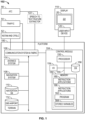
FIG. 1 is a block diagram of a system for alerting when an intruder trend vector is predicted to intercept with an ownship taxi path, in accordance with an exemplary embodiment; -
FIG. 2 is a flow chart for a method for alerting when an intruder trend vector is predicted to intercept with an ownship taxi path, in accordance with an exemplary embodiment; and -
FIG. 3 is an illustration of an avionic display showing an alert when an intruder trend vector is predicted to intercept with an ownship taxi path, in accordance with an exemplary embodiment. - The following detailed description is merely illustrative in nature and is not intended to limit the embodiments of the subject matter or the application and uses of such embodiments. As used herein, the word "exemplary" means "serving as an example, instance, or illustration." Thus, any embodiment described herein as "exemplary" is not necessarily to be construed as preferred or advantageous over other embodiments. The embodiments described herein are exemplary embodiments provided to enable persons skilled in the art to make or use the invention and not to limit the scope of the invention that is defined by the claims. Furthermore, there is no intention to be bound by any expressed or implied theory presented in the preceding technical field, background, summary, or the following detailed description.
- As mentioned, it is desirable to update and improve upon navigation systems to add alerting when an intruder trend vector is predicted to intercept with an ownship taxi path.
- Exemplary embodiments provide a technical solution to this problem in the form of a control module (
FIG. 1 , 104). The disclosed control module operates on available input and evaluates trend vectors transmitted from traffic that is nearby the ownship to predict whether the traffic will intercept with the ownship taxi path. The figures and descriptions below provide more detail. - Turning now to
FIG. 1 , in an embodiment, the system for alerting when an intruder trend vector is predicted to intercept with an ownship taxi path 102 (also referred to herein as "system" 102) is generally associated with amobile platform 100. In various embodiments, themobile platform 100 is an aircraft, and is referred to asaircraft 100. Thesystem 102 embodies acontrol module 104. In some embodiments, thecontrol module 104 may be integrated within a preexisting mobile platform management system, avionics system, cockpit display system (CDS), flight controls system (FCS), or aircraft flight management system (FMS). Although thecontrol module 104 is shown as an independent functional block, onboard theaircraft 100, in other embodiments, it may exist in an electronic flight bag (EFB) or portable electronic device (PED), such as a tablet, cellular phone, or the like. In embodiments in which the control module is within an EFB or a PED, thedisplay system 118 anduser input device 120 may also be part of the EFB or PED. - The
control module 104 may be operationally coupled to any combination of the following aircraft systems: a communication system andfabric 106; a source of real-time aircraft state data, such as anavigation system 108; a source of prescribed flight plan data, such as a navigation database (NavDB 110); one ormore databases 112; adisplay system 118; and auser input device 120. Thecontrol module 104 is communicatively coupled to a source of notice to airmen (NOTAM 52) data,air traffic control 56, and a source oftraffic data 54, such as automatic dependent surveillance broadcast (ADS-B) and traffic information service broadcast (TIS-B). In various embodiments, thecontrol module 104 is additionally operationally coupled to one ormore avionics systems 114, and a speech to text converter/features extractor 122. The functions of these aircraft systems, and their interaction, are described in more detail below. - Real-time aircraft state data may include any of: an instantaneous location (e.g., the latitude, longitude, orientation), an instantaneous heading (i.e., the direction the aircraft is traveling in relative to some reference), a flight path angle, a vertical speed, a ground speed, an instantaneous altitude (or height above ground level), and a current phase of flight of the
aircraft 100. As used herein, "real-time" is interchangeable with current and instantaneous. In some embodiments, the real-time aircraft state data is generated by thenavigation system 108. Thenavigation system 108 may be realized as including a global positioning system (GPS), inertial reference system (IRS), or a radio-based navigation system (e.g., VHF omnidirectional radio range (VOR) or long-range aid to navigation (LORAN)), and may include one or more navigational radios or other sensors suitably configured to support operation of the FMS, as will be appreciated in the art. The data provided by thenavigation system 108 is referred to as navigation data (also referred to herein as the real-time aircraft state data). The real-time aircraft state data is made available, generally by way of the communication system andfabric 106, so other components, such as thecontrol module 104 and thedisplay system 118, may further process and/or handle the aircraft state data. - Prescribed flight plan (FP) data may include a series of intended geospatial midpoints between a departure and an arrival, as well as performance data associated with each of the geospatial midpoints (non-limiting examples of the performance data include intended navigation data, such as: intended airspeed, intended altitude, intended acceleration, intended flight path angle, and the like). A source of a prescribed flight plan data may be a storage location or a user input device. In various embodiments, the navigation database, NavDB 110, is the source of a prescribed flight plan. The navigation database (NavDB 110) is a storage location that may also maintain a database of flight plans, and/or information regarding terrain and airports and/or other potential landing locations (or destinations) for the
aircraft 100. - In various embodiments, the
avionics systems 114 provide aircraft performance data and sensed data for a variety ofaircraft 100 subsystems. Examples of the aircraft performance data include: engine thrust level, fuel level, flap configuration, braking status, temperature control system status, and the like. As may be appreciated, theavionics systems 114 may therefore include a variety of on-board detection sensors and may be operationally coupled to thecontrol module 104, central management computer, or FMS. - The communications system and
fabric 106 is configured to support instantaneous (i.e., real time or current) communications between onboard systems (i.e., thenavigation system 108, thenavigation database 110, thedatabase 112, and the avionics systems 114), thecontrol module 104, and the one or more external data source(s). As a functional block, the communications system andfabric 106 represents one or more transmitters, receivers, and the supporting communications hardware and software required for components of thesystem 102 to communicate as described herein. In various embodiments, the communications system andfabric 106 may have additional communications not directly relied upon herein, such as bidirectional pilot-to-ATC (air traffic control) communications via a datalink; support for an automatic dependent surveillance broadcast system (ADS-B); a communication management function (CMF) uplink; a terminal wireless local area network (LAN) unit (TWLU); an instrument landing system (ILS); and, any other suitable radio communication system that supports communications between theaircraft 100 and the various external source(s). In various embodiments, thecontrol module 104 and communications system andfabric 106 also support controller pilot data link communications (CPDLC) withCPDLC 52, such as through an aircraft communication addressing and reporting system (ACARS) router; in various embodiments, this feature may be referred to as a communications management unit (CMU) or communications management function (CMF). In summary, the communications system andfabric 106 may allow theaircraft 100 and thecontrol module 104 to receive information that would otherwise be unavailable to the pilot and/or co-pilot using only the onboard systems. - External sources communicate with the
aircraft 100 and thecontrol module 104, generally, by way of the communication system andfabric 106. External sources include: NOTAM 52 (which includes CPDLC 52), traffic data system(s) 54; air traffic control (ATC) 56; and a variety of other radio inputs, such as source(s) of the radio signals used by the an instrument landing system (ILS), and weather and surface data sources, such as a source for meteorological terminal aviation weather reports (METARS), automatic terminal information service (ATIS), datalink ATIS (D-ATIS), automatic surface observing system (ASOS). The traffic data system(s) 54 include numerous systems for providing real-time neighbor/relevant traffic data and information. For example,traffic data sources 54 may include any combination of: traffic collision avoidance system (TCAS), automatic dependent surveillance broadcast (ADS-B), traffic information system (TIS), crowd sourced traffic data and/or another suitable avionics system. Flight traffic information that is received from the traffic data system may include, for each neighbor aircraft of a plurality of neighbor aircraft, one or more of a respective instantaneous location and heading, vertical speed, ground speed, instantaneous altitude, and aircraft identification. - The
user input device 120 and thecontrol module 104 are cooperatively configured to allow a user (e.g., a pilot, co-pilot, or crew member) to interact with display devices in thedisplay system 118 and/or other elements of thesystem 102, as described in greater detail below. Depending on the embodiment, theuser input device 120 may be realized as a cursor control device (CCD), keypad, touchpad, keyboard, mouse, touch panel (or touchscreen), joystick, knob, line select key, voice controller, gesture controller, or another suitable device adapted to receive input from a user. When theuser input device 120 is configured as a touchpad or touchscreen, it may be integrated with thedisplay system 118. As used herein, theuser input device 120 may be used by a pilot to communicate withATC 56, to modify or upload theprogram product 166, etc. In various embodiments, thedisplay system 118 anduser input device 120 are onboard theaircraft 100 and are also operationally coupled to the communication system andfabric 106. In some embodiments, thecontrol module 104,user input device 120, anddisplay system 118 are configured as a control display unit(CDU). - In various embodiments, the
control module 104, alone, or as part of a central management computer (CMS) or a flight management system (FMS), draws upon data and information from thenavigation system 108 and theNavDB 110 to provide real-time flight guidance foraircraft 100. The real time flight guidance may be provided to a user by way of commands for thedisplay system 118, an audio system, or the like. For example, thecontrol module 104 may compare an instantaneous position and heading of theaircraft 100 with the prescribed flight plan data for theaircraft 100 and generate display commands to renderimages 22 showing these features. Thecontrol module 104 may further associate a respective airport, its geographic location, runways (and their respective orientations and/or directions), instrument procedures (e.g., approach procedures, arrival routes and procedures, takeoff procedures, and the like), airspace restrictions, and/or other information or attributes associated with the respective airport (e.g., widths and/or weight limits of taxi paths, the type of surface of the runways or taxi path, and the like) with the instantaneous position and heading of theaircraft 100 and/or with the navigation plan for theaircraft 100. - The
control module 104 generates display commands for thedisplay system 118 to cause thedisplay device 20 to render thereon theimage 22, comprising various graphical user interface elements, tables, icons, alerts, menus, buttons, and pictorial images, as described herein. Thedisplay system 118 is configured to continuously receive and process the display commands from thecontrol module 104. Thedisplay system 118 includes adisplay device 20 for presenting animage 22. In various embodiments described herein, thedisplay system 118 includes a synthetic vision system (SVS), and theimage 22 is a SVS image. In exemplary embodiments, thedisplay device 20 is realized on one or more electronic display devices configured as any combination of: a head up display (HUD), an alphanumeric display, a vertical situation display (VSD) and a lateral navigation display (ND). - Renderings on the
display system 118 may be processed by a graphics system, components of which may be integrated into thedisplay system 118 and/or be integrated within thecontrol module 104. Display methods include various types of computer generated symbols, text, and graphic information representing, for example, pitch, heading, flight path, airspeed, altitude, runway information, waypoints, targets, obstacles, terrain, and required navigation performance (RNP) data in an integrated, multi-color or monochrome form. Display methods also include various formatting techniques for visually distinguishing objects and routes from among other similar objects and routes. In an embodiment, the Bokeh effect is used for emphasizing relevant signage with respect to remaining signage. Thecontrol module 104 may be said to display various images and selectable options described herein. In practice, this may mean that thecontrol module 104 generates display commands, and, responsive to receiving the display commands from thecontrol module 104, thedisplay system 118 displays, renders, or otherwise visually conveys on thedisplay device 20, the graphical images associated with operation of theaircraft 100, and specifically, the graphical images as directed by thecontrol module 104. - In addition to providing flight guidance, in various embodiments, any combination of the
control module 104,user input device 120,avionics systems 114, and communication system andfabric 106, may be coupled to thedisplay system 118 such that thedisplay system 118 may additionally generate or render, on thedisplay device 20, real-time avionics systems information associated withrespective aircraft 100 systems and components. - In various embodiments, the
control module 104 is additionally operationally coupled to one ormore databases 112. Thedatabases 112 may include one or more of: a runway awareness and advisory system (RAAS) database and an Aerodrome Mapping Database (AMDB). In various embodiments, each of these may include an airport features database, having therein maps and geometries, including runway records with corresponding runway threshold locations. The AMDB may also include airport status data for the runways and/or taxi paths at the airport; the airport status data indicating operational status and directional information for the taxi paths (or portions thereof). In some embodiments, thedatabases 112 may include a terrain database, having therein topographical information for the airport and surrounding environment. - The
control module 104 performs the functions of thesystem 102. As used herein, the term "module" refers to any means for facilitating communications and/or interaction between the elements of thesystem 102 and performing additional processes, tasks and/or functions to support operation of thesystem 102, as described herein. In various embodiments, thecontrol module 104 may be any hardware, software, firmware, electronic control component, processing logic, and/or processor device, individually or in any combination. Depending on the embodiment, thecontrol module 104 may be implemented or realized with a general purpose processor (shared, dedicated, or group) controller, microprocessor, or microcontroller, and memory that executes one or more software or firmware programs; a content addressable memory; a digital signal processor; an application specific integrated circuit (ASIC), a field programmable gate array (FPGA); any suitable programmable logic device; combinational logic circuit including discrete gates or transistor logic; discrete hardware components and memory devices; and/or any combination thereof, designed to perform the functions described herein. - Accordingly, in
FIG. 1 , an embodiment of thecontrol module 104 is depicted as a computer system including aprocessor 150 and amemory 152. Theprocessor 150 may comprise any type of processor or multiple processors, single integrated circuits such as a microprocessor, or any suitable number of integrated circuit devices and/or circuit boards working in cooperation to carry out the described operations, tasks, and functions by manipulating electrical signals representing data bits at memory locations in the system memory, as well as other processing of signals. Thememory 152 may comprise RAM memory, ROM memory, flash memory, registers, a hard disk, or another suitable non-transitory short or long-term storage media capable of storing computer-executable programming instructions or other data for execution. Thememory 152 may be located on and/or co-located on the same computer chip as theprocessor 150. Generally, thememory 152 maintains data bits and may be utilized by theprocessor 150 as storage and/or a scratch pad during operation. Specifically, thememory 152 stores instructions andapplications 160. Information in thememory 152 may be organized and/or imported from an external data source 50 during an initialization step of a process; it may also be programmed via auser input device 120. During operation, theprocessor 150 loads and executes one or more programs, algorithms and rules embodied as instructions andapplications 160 contained within thememory 152 and, as such, controls the general operation of thecontrol module 104 as well as thesystem 102. - The
novel program 162 includes rules and instructions which, when executed, convert theprocessor 150/memory 152/database 156 configuration into thecontrol module 104, which is a novel "contextual alerts" control module that performs the functions, techniques, and processing tasks associated with the operation of thesystem 102.Novel program 162 and associated storedvariables 164 may be stored in a functional form on computer readable media, for example, as depicted, inmemory 152. While the depicted exemplary embodiment is described in the context of a fully functioning computer system, those skilled in the art will recognize that the mechanisms of the present disclosure are capable of being distributed as aprogram product 166. As aprogram product 166, one or more types of non-transitory computer-readable signal bearing media may be used to store and distribute theprogram 162, such as a non-transitory computer readable medium bearing theprogram 162 and containing therein additional computer instructions for causing a computer processor (such as the processor 150) to load and execute theprogram 162. Such aprogram product 166 may take a variety of forms, and the present disclosure applies equally regardless of the type of computer-readable signal bearing media used to carry out the distribution. Examples of signal bearing media include: recordable media such as floppy disks, hard drives, memory cards and optical disks, and transmission media such as digital and analog communication links. It will be appreciated that cloud-based storage and/or other techniques may also be utilized in certain embodiments. - In executing the process described herein, the
processor 150 specifically loads the instructions embodied in theprogram 162, thereby being programmed withprogram 162. During execution ofprogram 162, theprocessor 150, thememory 152, and adatabase DB 156 form a novel dynamic processing engine that performs the processing activities of thesystem 102. - In various embodiments, the processor/memory unit of the
control module 104 may be communicatively coupled (via a bus 155) to an input/output (I/O)interface 154, and adatabase 156. Thebus 155 serves to transmit programs, data, status and other information or signals between the various components of thecontrol module 104. Thebus 155 can be any suitable physical or logical means of connecting computer systems and components. This includes, but is not limited to, direct hard-wired connections, fiber optics, infrared and wireless bus technologies. - The I/
O interface 154 enablesintra control module 104 communication, as well as communications between thecontrol module 104 andother system 102 components, and between thecontrol module 104 and the external data sources via the communication system andfabric 106. The I/O interface 154 may include one or more network interfaces and can be implemented using any suitable method and apparatus. In various embodiments, the I/O interface 154 is configured to support communication from an external system driver and/or another computer system. In one embodiment, the I/O interface 154 is integrated with the communication system andfabric 106 and obtains data from external data source(s) directly. Also, in various embodiments, the I/O interface 154 may support communication with technicians, and/or one or more storage interfaces for direct connection to storage apparatuses, such as thedatabase 156. - In some embodiments, the
database 156 is part of thememory 152. In various embodiments, thedatabase 156 and thedatabase 112 are integrated, either within thecontrol module 104 or external to it. Accordingly, in some embodiments, the airport features data and terrain features are pre-loaded and internal to thecontrol module 104. - The
system 102 may make its determinations and selections in accordance with a method such asmethod 200 ofFIG. 2 . With continued reference toFIG. 1 , a flow chart is provided for amethod 200 for providing asystem 102, in accordance with various exemplary embodiments.Method 200 represents various embodiments of a method for selecting an accurate runway record. For illustrative purposes, the following description ofmethod 200 may refer to elements mentioned above in connection withFIG. 1 . In practice, portions ofmethod 200 may be performed by different components of the described system. It should be appreciated thatmethod 200 may include any number of additional or alternative tasks, the tasks shown inFIG. 2 need not be performed in the illustrated order, andmethod 200 may be incorporated into a more comprehensive procedure or method having additional functionality not described in detail herein. Moreover, one or more of the tasks shown inFIG. 2 could be omitted from an embodiment of themethod 200 if the intended overall functionality remains intact. - At 202, the method receives navigation data. At 204, the intended destination or runway for the ownship aircraft is received. With reference to
FIG. 3 , and with continued reference toFIG. 2 , at 206, thesystem 102 constructs a route (i.e., the taxi path 302) for theaircraft 100 and displays it on anavionic display 300. It is assumed that thecontrol module 104 has already received the destination or the assigned runway; constructed, using airport feature data, a route for theaircraft 100 to travel from its current location to its destination or its assigned runway (the route including a travel direction); and generated display commands for rendering an image showing theaircraft 100 at the current location and heading on the airport field. Theimages 22 generated by thedisplay system 118, responsive to display commands, and are understood to be based on current aircraft state data and to be dynamically modified responsive to continuously obtaining and processing the current aircraft state data. Theimages 22 may also be continuously updated to reflect real-time changes with respect to terrain, airport features, weather, and neighbor traffic/relevant traffic. - The
avionic display 300 also displaysintersection 304, at which theaircraft 100 is currently entering, andintersection 306, which is further down the path of theaircraft 100. At 208, traffic data is received from external sources such astraffic source 52. At 210, thesystem 102 projects thetrend vector 308 of a traffic that is off screen (off screen to the right in this example) and on trend to intercept with theaircraft 100 in theintersection 306. Thesystem 102 predicts an intersection of the traffic with thetaxi path 302. - At 212, the system converts the projected intersection at
intersection 306 into an amount of time (time delay) until the intersection atintersection 306 will occur, barring further action, and compares the time delay to predefined thresholds. A first predefined threshold may represent a caution alert and a second predefined threshold (a smaller amount of time than that of the first predefined threshold) may define a critical alert. In an example, the first time delay is in the range of 7-10 seconds and the second time delay is in the range of 5-6 seconds. - At 214, the
system 102 visually distinguishes the predicted intersection on theavionic display 22. Thesystem 102 may reference predefined display rules to determine a rendering technique to performstep 214. For example, the color yellow or amber may be used for the cautionary alert and the color red may be used for the critical alert. In addition, the predefined display rules may specify the size and shape of the visual alert. In an example, as shown inFIG. 3 , the size of thevisual alert 310 includes an area with a width equal to a width of the displayed thetaxi path 302, and a length that is equal to anentire length 312 of the intersection. In an embodiment, upon determining that the traffic is out of a field of view of the image, thesystem 102 renders the trend vector associated with the traffic with a dotted or dashed line. - The
avionic display 300 ofFIG. 3 of provides a non-limiting example of the provided technological enhancement over other alert systems. As used herein, the intended/assigned destination may also be an assigned taxiway, and the assigned runway may include information for the runway or taxi way, such as an assigned gate and an exit for the runway or taxiway. - In some embodiments, the
system 102 includes a speech-to-text converter 122, each operationally coupled to thecontrol module 104. In these embodiments, thecontrol module 104 is further configured to: receive the intended destination or the assigned runway as speech, embedded within a speech command from air traffic control (ATC) or from a CPDLC command; convert the speech command into text; and extract the intended destination or assigned runway from the text. - Although an exemplary embodiment of the present disclosure has been described above in the context of a fully-functioning computer system (e.g.,
system 102 described above in conjunction withFIG. 1 ), those skilled in the art will recognize that the mechanisms of the present disclosure are capable of being distributed as a program product (e.g., an Internet-disseminated program 9 or software application) and, further, that the present teachings apply to the program product regardless of the particular type of computer-readable media (e.g., hard drive, memory card, optical disc, etc.) employed to carry-out its distribution. - Terms such as "comprise," "include," "have," and variations thereof are utilized herein to denote non-exclusive inclusions. Such terms may thus be utilized in describing processes, articles, apparatuses, and the like that include one or more named steps or elements but may further include additional unnamed steps or elements.
- While at least one exemplary embodiment has been presented in the foregoing detailed description, it should be appreciated that a vast number of variations exist. It should also be appreciated that the exemplary embodiment or exemplary embodiments are only examples, and are not intended to limit the scope, applicability, or configuration of the disclosure in any way. Rather, the foregoing detailed description will provide those skilled in the art with a convenient road map for implementing the exemplary embodiment or exemplary embodiments. It should be understood that various changes can be made in the function and arrangement of elements without departing from the scope of the disclosure as set forth in the appended claims and the legal equivalents thereof.
Claims (15)
- A system for alerting, in an ownship aircraft, when a trend vector associated with a traffic aircraft that is external to the ownship aircraft is predicted to intercept a travel route of the ownship aircraft, the system comprising:
a control module operationally coupled to receive real-time aircraft state data, flight plan data, and traffic data associated with the traffic aircraft, the real-time aircraft state data including a current location, a current heading, and a current speed of the ownship aircraft, the flight plan data including an intended destination of the ownship aircraft, the control module configured to:process the real-time aircraft state data, the flight plan data, and the traffic data;construct the travel route of the ownship aircraft from the current location to the intended destination;generate display commands that cause a display device to render an image showing the ownship aircraft at the current location and at the current heading;generate the trend vector associated with the traffic aircraft;predict a location of an intersection of the trend vector and the travel route;determine an amount of time it will take for the ownship aircraft, at the current location, the current heading, and the current speed, to reach the location of the intersection; andgenerate display commands that cause the display device to generate an alert that visually distinguishes the location on the image based at least in part on the amount of time. - The system of claim 1, wherein the control module is further configured to:process the traffic data to determine if the traffic aircraft is out of a field of view of the image; andwhen the traffic aircraft is out of the field of view of the image, generate display commands that cause the display device to render the trend vector as a dotted line that extends from the location of the intersection toward the traffic aircraft.
- The system according to any one of the preceding claims, wherein the control module is further configured to:conduct comparisons of the amount of time to a plurality of threshold time values; andgenerate display commands that cause the display device to visually distinguish the alert based on the comparisons.
- The system according to any one of the preceding claims 3, wherein the control module is further configured to:
generate display commands that cause the display device to render the alert using different colors based on the comparisons. - The system according to any one of the preceding claims, wherein the plurality of threshold time values include a first threshold time value and a second threshold time value, the first threshold time value greater than the second threshold time value.
- The system according to any one of the preceding claims, wherein the control module is further configured to:generate display commands that cause the display device to render the alert using a first color when the amount of time is less than the first threshold time value and greater than the second threshold time value; andgenerate display commands that cause the display device to render the alert using a second color when the amount of time is less than the second threshold time value.
- The system according to any one of the preceding claims, wherein the control module is further configured to generate display commands that cause the display device to render the alert as a predefined size and shaped.
- The system according to any one of the preceding claims 1, further comprising:a real-time aircraft state data source configured to supply the real-time aircraft state data;a flight plan data source configured to supply the flight plan data; anda traffic data source configured to supply the traffic data.
- The system according to any one of the preceding claims, wherein:the control module is further operationally coupled to receive airport feature data, the airport feature data representative of an airport field; andthe control module is further configured to process the airport feature data and generate display commands that cause the display device to render the image showing the ownship aircraft at the current location and heading on the airport field.
- The system according to any one of the preceding claims, further comprising:a real-time aircraft state data source configured to supply the real-time aircraft state data;a flight plan data source configured to supply the flight plan data;a traffic data source configured to supply the traffic data; andan airport feature data source configured to supply the airport feature data.
- A method for alerting, in an ownship aircraft, when a trend vector associated with a traffic aircraft that is external to the ownship aircraft is predicted to intercept a travel route of the ownship aircraft, the method comprising the steps of:receiving, in a control module, real-time aircraft state data, flight plan data, and traffic data associated with the traffic aircraft, the real-time aircraft state data including a current location, a current heading, and a current speed of the ownship aircraft, the flight plan data including an intended destination of the ownship aircraft;processing, in the control module, the real-time aircraft state data, the flight plan data, and the traffic data;constructing, in the control module, the travel route of the ownship aircraft from the current location to the intended destination;generating display commands, in the control module, that cause a display device to render an image showing the ownship aircraft at the current location and at the current heading;generating, in the control module, the trend vector associated with the traffic aircraft;predicting, in the control module, a location of an intersection of the trend vector and the travel route;determining, in the control module, an amount of time it will take for the ownship aircraft, at the current location, the current heading, and the current speed, to reach the location of the intersection; andgenerating display commands, in the control module, that cause the display device to generate an alert that visually distinguishes the location on the image based at least in part on the amount of time.
- The method of claim 11, further comprising:processing the traffic data, in the control module, to determine if the traffic aircraft is out of a field of view of the image; andwhen the traffic aircraft is out of the field of view of the image, generating display commands, in the control module, that cause the display device to render the trend vector as a dotted line that extends from the location of the intersection toward the traffic aircraft.
- The method according to any one of the preceding claims, further comprising:conducting comparisons, in the control module, of the amount of time to a plurality of threshold time values; andgenerating display commands, in the control module, that cause the display device to visually distinguish the alert based on the comparisons.
- The method according to any one of the preceding claims, further comprising:
generating display commands, in the control module, that cause the display device to render the alert using different colors based on the comparisons. - The method according to any one of the preceding claims, wherein the plurality of threshold time values include a first threshold time value and a second threshold time value, the first threshold time value greater than the second threshold time value.
Applications Claiming Priority (2)
| Application Number | Priority Date | Filing Date | Title |
|---|---|---|---|
| IN202111044413 | 2021-09-30 | ||
| US17/663,467 US20230093956A1 (en) | 2021-09-30 | 2022-05-16 | Systems and methods for alerting when an intruder trend vector is predicted to intercept with an aircraft taxi path |
Publications (1)
| Publication Number | Publication Date |
|---|---|
| EP4160572A1 true EP4160572A1 (en) | 2023-04-05 |
Family
ID=83283281
Family Applications (1)
| Application Number | Title | Priority Date | Filing Date |
|---|---|---|---|
| EP22195044.7A Pending EP4160572A1 (en) | 2021-09-30 | 2022-09-12 | Systems and methods for alerting when an intruder trend vector is predicted to intercept with an aircraft taxi path |
Country Status (1)
| Country | Link |
|---|---|
| EP (1) | EP4160572A1 (en) |
Citations (4)
| Publication number | Priority date | Publication date | Assignee | Title |
|---|---|---|---|---|
| US20160063869A1 (en) * | 2014-08-29 | 2016-03-03 | Honeywell International Inc. | System and method for displaying traffic and associated alerts on a three-dimensional airport moving map display |
| US20160196754A1 (en) * | 2015-01-06 | 2016-07-07 | Honeywell International Inc. | Airport surface monitoring system with wireless network interface to aircraft surface navigation system |
| US20180357911A1 (en) * | 2017-03-14 | 2018-12-13 | Architecture Technology Corporation | Advisor system and method |
| US20200090531A1 (en) * | 2018-09-18 | 2020-03-19 | Honeywell International Inc. | Systems and methods for contextual alerts during ground operations |
-
2022
- 2022-09-12 EP EP22195044.7A patent/EP4160572A1/en active Pending
Patent Citations (4)
| Publication number | Priority date | Publication date | Assignee | Title |
|---|---|---|---|---|
| US20160063869A1 (en) * | 2014-08-29 | 2016-03-03 | Honeywell International Inc. | System and method for displaying traffic and associated alerts on a three-dimensional airport moving map display |
| US20160196754A1 (en) * | 2015-01-06 | 2016-07-07 | Honeywell International Inc. | Airport surface monitoring system with wireless network interface to aircraft surface navigation system |
| US20180357911A1 (en) * | 2017-03-14 | 2018-12-13 | Architecture Technology Corporation | Advisor system and method |
| US20200090531A1 (en) * | 2018-09-18 | 2020-03-19 | Honeywell International Inc. | Systems and methods for contextual alerts during ground operations |
Similar Documents
| Publication | Publication Date | Title |
|---|---|---|
| EP1835369B1 (en) | Ground incursion avoidance system and display | |
| EP3627477B1 (en) | Systems and methods for contextual alerts during ground operations | |
| US10290217B1 (en) | Systems and methods for evaluation of runway changes | |
| EP2781884B1 (en) | A system and method for graphically displaying airspace speed data | |
| US10762793B2 (en) | Systems and methods for selecting accurate runway records for use in cockpit display systems | |
| US10706726B2 (en) | Multiple flight data reference for a specific selection on a vertical and lateral display | |
| US10515554B1 (en) | Systems and methods for time-based viewing of predicted clearance requests | |
| US11275388B2 (en) | Systems and methods for an enhanced stable approach monitor | |
| US20200175628A1 (en) | Systems and methods for predicting weather impact on an aircraft | |
| EP3628976B1 (en) | Systems and methods for dynamic readouts for primary flight displays | |
| EP3628977B1 (en) | Systems and methods for associating critical flight reference data with a flight path vector symbol | |
| US10565886B2 (en) | Systems and methods for predicting loss of separation events | |
| EP3626552A1 (en) | Systems and methods for optimizing landing performance | |
| US20210253268A1 (en) | Systems and methods that optimize speed brake operations | |
| EP4160572A1 (en) | Systems and methods for alerting when an intruder trend vector is predicted to intercept with an aircraft taxi path | |
| US20230093956A1 (en) | Systems and methods for alerting when an intruder trend vector is predicted to intercept with an aircraft taxi path | |
| US11587447B2 (en) | Dynamically modifiable parameters in required time of arrival (RTA) regions of an assigned flight path | |
| EP3751311B1 (en) | Three-dimensional weather display systems and methods that provide replay options | |
| US10922985B2 (en) | Systems and methods for dynamic implementation of increased glide slope angles in approach procedures | |
| EP3852084A1 (en) | Systems and methods that optimize speed brake operations |
Legal Events
| Date | Code | Title | Description |
|---|---|---|---|
| PUAI | Public reference made under article 153(3) epc to a published international application that has entered the european phase |
Free format text: ORIGINAL CODE: 0009012 |
|
| STAA | Information on the status of an ep patent application or granted ep patent |
Free format text: STATUS: THE APPLICATION HAS BEEN PUBLISHED |
|
| AK | Designated contracting states |
Kind code of ref document: A1 Designated state(s): AL AT BE BG CH CY CZ DE DK EE ES FI FR GB GR HR HU IE IS IT LI LT LU LV MC MK MT NL NO PL PT RO RS SE SI SK SM TR |
|
| P01 | Opt-out of the competence of the unified patent court (upc) registered |
Effective date: 20230525 |
|
| STAA | Information on the status of an ep patent application or granted ep patent |
Free format text: STATUS: REQUEST FOR EXAMINATION WAS MADE |
|
| 17P | Request for examination filed |
Effective date: 20230929 |
|
| RBV | Designated contracting states (corrected) |
Designated state(s): AL AT BE BG CH CY CZ DE DK EE ES FI FR GB GR HR HU IE IS IT LI LT LU LV MC MK MT NL NO PL PT RO RS SE SI SK SM TR |