EP4160316A1 - Developing cartridge - Google Patents
Developing cartridge Download PDFInfo
- Publication number
- EP4160316A1 EP4160316A1 EP22210224.6A EP22210224A EP4160316A1 EP 4160316 A1 EP4160316 A1 EP 4160316A1 EP 22210224 A EP22210224 A EP 22210224A EP 4160316 A1 EP4160316 A1 EP 4160316A1
- Authority
- EP
- European Patent Office
- Prior art keywords
- end portion
- casing
- plate
- blade
- developing cartridge
- Prior art date
- Legal status (The legal status is an assumption and is not a legal conclusion. Google has not performed a legal analysis and makes no representation as to the accuracy of the status listed.)
- Pending
Links
Images



Classifications
-
- G—PHYSICS
- G03—PHOTOGRAPHY; CINEMATOGRAPHY; ANALOGOUS TECHNIQUES USING WAVES OTHER THAN OPTICAL WAVES; ELECTROGRAPHY; HOLOGRAPHY
- G03G—ELECTROGRAPHY; ELECTROPHOTOGRAPHY; MAGNETOGRAPHY
- G03G15/00—Apparatus for electrographic processes using a charge pattern
- G03G15/06—Apparatus for electrographic processes using a charge pattern for developing
- G03G15/08—Apparatus for electrographic processes using a charge pattern for developing using a solid developer, e.g. powder developer
- G03G15/0806—Apparatus for electrographic processes using a charge pattern for developing using a solid developer, e.g. powder developer on a donor element, e.g. belt, roller
- G03G15/0812—Apparatus for electrographic processes using a charge pattern for developing using a solid developer, e.g. powder developer on a donor element, e.g. belt, roller characterised by the developer regulating means, e.g. structure of doctor blade
-
- G—PHYSICS
- G03—PHOTOGRAPHY; CINEMATOGRAPHY; ANALOGOUS TECHNIQUES USING WAVES OTHER THAN OPTICAL WAVES; ELECTROGRAPHY; HOLOGRAPHY
- G03G—ELECTROGRAPHY; ELECTROPHOTOGRAPHY; MAGNETOGRAPHY
- G03G15/00—Apparatus for electrographic processes using a charge pattern
- G03G15/06—Apparatus for electrographic processes using a charge pattern for developing
- G03G15/08—Apparatus for electrographic processes using a charge pattern for developing using a solid developer, e.g. powder developer
- G03G15/0822—Arrangements for preparing, mixing, supplying or dispensing developer
- G03G15/0865—Arrangements for supplying new developer
-
- G—PHYSICS
- G03—PHOTOGRAPHY; CINEMATOGRAPHY; ANALOGOUS TECHNIQUES USING WAVES OTHER THAN OPTICAL WAVES; ELECTROGRAPHY; HOLOGRAPHY
- G03G—ELECTROGRAPHY; ELECTROPHOTOGRAPHY; MAGNETOGRAPHY
- G03G21/00—Arrangements not provided for by groups G03G13/00 - G03G19/00, e.g. cleaning, elimination of residual charge
- G03G21/16—Mechanical means for facilitating the maintenance of the apparatus, e.g. modular arrangements
- G03G21/18—Mechanical means for facilitating the maintenance of the apparatus, e.g. modular arrangements using a processing cartridge, whereby the process cartridge comprises at least two image processing means in a single unit
- G03G21/1803—Arrangements or disposition of the complete process cartridge or parts thereof
- G03G21/181—Manufacturing or assembling, recycling, reuse, transportation, packaging or storage
Definitions
- the present disclosure relates to a developing cartridge.
- a conventional image forming apparatus including a cartridge is disclosed in U.S. Patent Application Publication No. 2017/0115603 .
- the cartridge disclosed in U.S. Patent Application Publication No. 2017/0115603 includes a developing roller.
- the developing roller is driven to rotate so that toner accommodated in the cartridge is carried on an outer circumferential surface of the developing roller.
- the photosensitive drum rotates in a state where the photosensitive drum contacts the developing roller, thereby transferring a toner image from the photosensitive drum onto a printing sheet.
- the cartridge disclosed in U.S. Patent Application Publication No. 2017/0115603 includes a first frame, a second frame, the developing roller, a blade, and a support member.
- the first frame is assembled with the second frame by means of welding to constitute a casing in which toner is accommodatable.
- the developing roller is supported by the casing so as to be rotatable about a rotational axis extending in a first direction.
- the blade extends in the first direction and a second direction, and has a first end portion in the second direction that is positioned close to the outer circumferential surface of the developing roller. Further, the blade is configured to regulate a thickness of a toner layer carried on the outer circumferential surface of the developing roller.
- the support member is fixed to an outer surface of the casing by a plurality of threads to support a second end portion in the second direction of the blade.
- a reinforcing rib connecting the first frame to the second frame is required in an interior of the casing in order to restrain deflection of the casing which may occur when external force is applied to the casing.
- providing the reinforcing rib may reduce an internal capacity of the casing, and also reduce a space for positioning a component such as an agitator within the casing.
- the disclosure provides a developing cartridge including: a casing; a developing roller; a blade; and a blade holder.
- the casing is configured to accommodate toner therein.
- the casing has a groove recessed inward of the casing.
- the developing roller is rotatable about a rotational axis extending in a first direction.
- the developing roller has an outer circumferential surface.
- the blade is configured to regulate a thickness of a layer of toner formed on the outer circumferential surface of the developing roller.
- the blade extends in a second direction toward the outer circumferential surface of the developing roller and having one end portion and another end portion in the second direction.
- the another end portion of the blade is positioned away from the one end portion of the blade in the second direction.
- the another end portion of the blade is positioned farther from the outer circumferential surface of the developing roller than the one end portion of the blade is from the outer circumferential surface of the developing roller.
- the blade holder supports the another end portion of the blade.
- the blade holder includes: a first plate extending in the second direction and supporting the another end portion of the blade; and a second plate extending from the first plate in a third direction crossing the second direction.
- the second plate has a distal end portion positioned within the groove.
- the casing includes an inner wall constituting the groove; and the distal end portion of the second plate is positioned within the groove with a gap between the distal end portion of the second plate and the inner wall.
- the distal end portion of the second plate is positioned within the groove with the gap between the distal end portion of the second plate and the inner wall in the second direction.
- the casing has one end portion and another end portion in the first direction, the another end portion of the casing being spaced apart from the one end portion of the casing in the first direction; and the groove is positioned at the casing at a position between the one end portion and the another end portion of the casing.
- the groove is positioned at the casing at a center portion of the casing between the one end portion and the another end portion of the casing.
- the blade holder is made of metal.
- the casing is made of resin.
- the blade holder is made of metal containing iron.
- the blade holder is made of stainless steel.
- the developing cartridge according to any one of the first to ninth aspects further includes a thread fixing the second plate to the casing.
- the developing cartridge according to the tenth aspect further includes another thread fixing the second plate to the casing, the thread and the another thread being arrayed in the first direction with a prescribed interval therebetween.
- the casing further has another groove recessed inward of the casing, the groove and the another groove being arrayed in the first direction with a prescribed interval therebetween; and the thread has a portion positioned between the groove and the another groove in the first direction.
- the developing cartridge according to any one of the first to twelfth aspects further includes a second blade holder supporting the another end portion of the blade, the second blade holder including: a third plate extending in the second direction and supporting the another end portion of the blade; and a fourth plate extending from the third plate in the third direction.
- the another end portion of the blade is nipped between the first plate and the third plate.
- each of the first plate and the third plate has one end portion and another end portion in the first direction.
- the developing cartridge further includes: a first fastening member fastening the one end portion of the first plate and the one end portion of the third plate to the casing; and a second fastening member fastening the another end portion of the first plate and the another end portion of the third plate to the casing.
- the casing includes: a first frame having the groove; and a second frame facing the first frame in the second direction, the second frame being assembled with the first frame to constitute the casing.
- the developing cartridge according to the fifteenth aspect further includes: a first agitator rotatable about a rotational axis extending in the first direction and configured to agitate toner accommodated in the casing; and a supply roller positioned between the first agitator and the developing roller and positioned opposite to the blade holder with respect to the developing roller in the second direction, the supply roller being rotatable about a rotational axis extending in the first direction and configured to supply the toner accommodated in the casing to the outer circumferential surface of the developing roller.
- the developing cartridge according to the sixteenth aspect further includes a second agitator positioned between the supply roller and the first agitator, the second agitator being rotatable about a rotational axis extending in the first direction.
- the second agitator is positioned closer to the supply roller than to the developing roller.
- the developing cartridge can prevent deflection of the casing without reducing the internal space of the casing.
- the distal end portion of the second plate of the blade holder is positioned within the groove of the casing.
- the casing can be reinforced with the second plate of the blade holder. Accordingly, deflection and deformation of the casing can be restrained even if an external force that reduces the internal space of the casing in the second direction is applied to the casing. Further, since the blade holder functions not only to reinforce the casing but also to support the blade, the numbers of parts and components can be reduced.
- the deflected casing is brought into abutment against the second plate of the blade holder, thereby restraining further deflection or deformation of the casing. Hence, excessive deflection or deformation of the casing does not occur.
- the groove is positioned at an intermediate portion in the first direction of the casing where deflection more likely to occur among an entire region of the casing in the first direction. Since the distal end portion of the second plate of the blade holder is positioned within this groove, deflection or deformation of the casing can be restrained well.
- the groove is positioned at the center portion in the first direction of the casing where the deflection most like occurs among the entire region of the casing in the first direction. Since the distal end portion of the second plate of the blade holder is positioned inside the groove, deflection or deformation of the casing can be efficiently restricted. Further, by positioning the groove only at the center portion in the first direction of the casing, a region at which the groove is positioned can be reduced, thereby causing material cost and machining cost to be reduced.
- the casing can be firmly reinforced with the metallic blade holder. Therefore, deflection or deformation of the casing can be desirably restrained.
- reinforcement of the casing by the blade holder can enhance rigidity of the casing, even if the casing has insufficient rigidity.
- the blade holder can be attached to the casing in a stable manner.
- the thread has a head portion exposed to an outside of the groove. Accordingly, a shaft portion of the thread can be inserted into a through-hole of the second plate so that a tip end portion of the shaft portion of the thread can threadingly engage with a threaded hole of the casing.
- the another end portion of the blade can be supported by nipping the another end portion between the first plate of the blade holder and the third plate of the second blade holder. This configuration can more stably support the blade.
- the first plate and the third plate are fastened by the first fastening member and the second fastening member so that the blade nipped between the first plate and the third plate can be more stably supported by the casing.
- the first fastening member and the second fastening member are provided at one end portions and the another end portions of the blade holder and the second blade holder, respectively, it is less likely that the first fastening member and the second fastening member interfere with laser beam emitted toward an outer circumferential surface of a photosensitive drum in contact with the developing roller in a case where the present disclosure is employed in a laser printer.
- a region of the internal space of the casing that cannot be sufficiently agitated by rotation of the first agitator can be agitated by rotation of the second agitator.
- a conventional structure for restraining deflection or deformation of the second frame toward the first frame such as a rib disposed in the internal space of the casing and connecting an inner surface of the first frame to an inner surface of the second frame, is not provided. Therefore, the second agitator can be provided at a position adjacent to the supply roller. Accordingly, sufficiently agitated toner can be continuously supplied from the supply roller to the developing roller.
- first direction a direction in which a rotational axis of a developing roller 22 extends
- second direction a direction in which a layer thickness regulation blade 24 extends toward an outer circumferential surface of the developing roller 22 and a direction opposite thereto
- first direction and second direction cross each other.
- the first direction and the second direction are perpendicular to each other.
- a direction crossing the first direction and the second direction will be referred to as "third direction”.
- the third direction is perpendicular to the first direction and the second direction.
- Fig. 1 is a schematic diagram of the image forming apparatus 100.
- the image forming apparatus 100 is an electro-photographic type printer.
- the image forming apparatus 100 may be a laser printer or an LED printer.
- the image forming apparatus 100 includes a main casing 101, a controller 102, the drum unit 1, and four developing cartridges 2.
- Each of the developing cartridge 2 is attachable to the drum unit 1.
- the drum unit 1 to which four developing cartridges 2 are attached is attachable to and detachable from the main casing 101.
- the image forming apparatus 100 is configured to form images on recording surfaces of printing sheets using toners supplied from four developing cartridges 2.
- the number of the developing cartridges 2 attachable to the drum unit 1 may be one to three, or more than five.
- the controller 102 is positioned in the main casing 101.
- the controller 102 is configured of, for example, a circuit board.
- the controller 102 includes a processor such as a CPU, and various memories.
- the controller 102 is configured to execute various processes in the image forming apparatus 100 by operating the processor in accordance with programs.
- the drum unit 1 illustrated in Fig. 1 includes four photosensitive drums 11 and a frame 12. Each of the photosensitive drums 11 is configured to transfer toner supplied from the corresponding one of the developing cartridges 2 to the printing sheets.
- the four photosensitive drums 11 are arranged to be spaced apart from one another.
- Each photosensitive drum 11 has a cylindrical-shaped outer circumferential surface and extends in the first direction.
- the outer circumferential surface of each photosensitive drum 11 is coated with photosensitive material. Further, each photosensitive drum 11 is rotatable about a rotational axis extending in the first direction.
- the frame 12 is configured to hold the four photosensitive drums 11.
- the frame 12 includes four cartridge-holding portions 120.
- the four cartridge-holding portions 120 are arrayed with each other with an interval between neighboring cartridge-holding portions 120.
- Each of the cartridge-holding portions 120 is configured to receive the corresponding one of the developing cartridges 2.
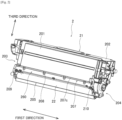
- Fig. 2 is a perspective view of the developing cartridge 2.
- Fig. 3 is a cross-sectional view of the developing cartridge 2 as viewed in the first direction.
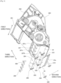
- Fig. 4 is a perspective view of the developing cartridge 2 in which a portion of the developing cartridge 2 is exploded.
- Fig. 5 is an enlarged view of a portion of the developing cartridge 2 illustrated in Fig. 3 .
- each of the developing cartridges 2 includes a casing 21, the developing roller 22, a supply roller 23, the layer thickness regulation blade 24 as an example of a blade, a first agitator 25, and a second agitator 26.
- the casing 21 is a container configured to accommodate toner therein.
- the casing 21 is made of resin.
- the casing 21 is configured of a first frame 201 and a second frame 202.
- the first frame 201 has a lid-like shape.
- the second frame 202 has a box shape and faces the first frame 201 in the second direction.
- the casing 21 is configured as a container.
- the casing 21 has one end portion 203 in the first direction, and another end portion 204 spaced apart from the one end portion 203 in the first direction.
- the first frame 201 has an opening 205 at one end portion thereof in the third direction. Detailed configuration of the first frame 201 will be described later.
- the developing roller 22 is rotatable about its rotational axis extending in the first direction.
- the developing roller 22 has one end portion in the first direction supported by the one end portion 203, and another end portion in the first direction supported by the other end portion 204.
- the developing roller 22 is positioned at the opening 205 of the casing 21. Hence, a portion of the outer circumferential surface of the developing roller 22 is exposed to an outside of the casing 21.
- the supply roller 23 illustrated in Figs. 3 and 5 is rotatable about a rotational axis extending in the first direction.
- the supply roller 23 has one end portion in the first direction supported by the one end portion 203, and another end portion in the first direction supported by the other end portion 204.
- the supply roller 23 is positioned between the first agitator 25 and the developing roller 22 in the third direction.
- the supply roller 23 is positioned adjacent to the developing roller 22.
- a portion of the supply roller 23 having an outer circumferential surface of the supply roller 23 is made from, for example, a rubber having elasticity.
- the outer circumferential surface of the supply roller 23 and the outer circumferential surface of the developing roller 22 are in contact with each other. Hence, toner can be supplied from the supply roller 23 to the outer circumferential surface of the developing roller 22.
- the layer thickness regulation blade 24 is configured to regulate thickness of a layer of toner formed on the outer circumferential surface of the developing roller 22 so that the thickness of the layer of toner is formed to a constant thickness.
- the layer thickness regulation blade 24 extends in the second direction toward the outer circumferential surface of the developing roller 22.
- the layer thickness regulation blade 24 is positioned between the one end portion 203 and the other end portion 204 of the casing 21 in the first direction.
- the layer thickness regulation blade 24 is positioned opposite to the supply roller 23 with respect to the developing roller 22 in the second direction.
- the layer thickness regulation blade 24 has one end portion in the second direction positioned adjacent to the developing roller 22 and in contact with the outer circumferential surface of the developing roller 22. Further, the layer thickness regulation blade 24 has another end portion in the second direction positioned away from the one end portion of the layer thickness regulation blade 24. The other end portion of the layer thickness regulation blade 24 is positioned farther from the outer circumferential surface of the developing roller 22 than the one end portion of the layer thickness regulation blade 24 is from the outer circumferential surface of the developing roller 22.
- An acting portion 24a made from rubber is provided at the one end portion in the second direction of the layer thickness regulation blade 24. The contact of the acting portion 24a with the toner layer on the outer circumferential surface of the developing roller 22 regulates the thickness of the toner layer.
- a portion of the layer thickness regulation blade 24 other than the acting portion 24a is formed of a metal plate.
- the other end portion in the second direction of the layer thickness regulation blade 24 is supported by the first frame 201 of the casing 21 through the first blade holder 250 and a second blade holder 260 (described later). A detailed configuration for supporting the other end portion of the layer thickness regulation blade 24 will be described later.
- the first agitator 25 illustrated in Fig. 3 is configured to agitate toner accommodated in an internal space of the casing 21.
- the first agitator 25 is rotatable about a rotational axis extending in the first direction.
- the first agitator 25 includes a blade 25a in a form of a film.
- the blade 25a has a distal end portion in contact with an inner surface of the casing 21.
- the rotation of the first agitator 25 about its rotational axis causes the blade 25a to rotate.
- the toner accommodated in the casing 21 is agitated.
- the second agitator 26 is also configured to agitate the toner accommodated in the internal space of the casing 21. Specifically, the second agitator 26 is configured to mainly agitate toner positioned in a region in the internal space in which toner is not sufficiently agitated by the first agitator 25. The second agitator 26 is positioned between the supply roller 23 and the first agitator 25 in the third direction. The second agitator 26 is rotatable about its rotational axis extending in the first direction. The second agitator 26 is positioned closer to the supply roller 23 than to the developing roller 22 in the third direction. With this configuration, toner agitated by the second agitator 26 can be efficiently supplied to the supply roller 23.
- the outer circumferential surface of the photosensitive drum 11 is exposed to laser beam after the outer circumferential surface is uniformly charged, so that an electrostatic latent image is formed on the outer circumferential surface of the photosensitive drum 11 on a basis of inputted print data.
- Toner accommodated in the casing 21 is supplied to the supply roller 23 while the toner is agitated by the first agitator 25 and the second agitator 26, and is then supplied to the developing roller 22 from the supply roller 23. More specifically, toner is entered into a portion between the developing roller 22 and the layer thickness regulation blade 24 in accordance with the rotation of the developing roller 22, and the toner is carried on the outer circumferential surface of the developing roller 22 as the thin toner layer having constant thickness.
- the toner carried on the outer circumferential surface of the developing roller 22 is supplied to the electrostatic latent image formed on the outer circumferential surface of the photosensitive drum 11, thereby causing the electrostatic latent image to become a visible image to form a toner image on the outer circumferential surface of the photosensitive drum 11.
- the formed toner image is transferred to the recording surface of the printing sheet and is then thermally fixed thereto, whereupon the printing process is terminated.
- the layer thickness regulation blade 24 is attached to and supported by the first frame 201 of the casing 21 using the support structure according to the embodiment.
- the support structure is configured by the first blade holder 250, the second blade holder 260, a plurality of grooves 207, a first thread 209 as an example of a first fastening member, a second thread 210 as an example of second fastening member, and a plurality of third threads 208.
- the first blade holder 250 illustrated in Figs. 3 to 5 is configured to support the other end portion in the second direction of the layer thickness regulation blade 24.
- the first blade holder 250 is made of metal. Although it is preferable that the metal contains iron, the first blade holder 250 may be made from stainless steel.
- the first blade holder 250 includes a first plate 251 and a second plate 252.
- the first plate 251 has a flat plate shape that extends in the first direction and the second direction.
- the first plate 251 has one end portion in the second direction closer to the developing roller 22 than another end portion in the second direction of the first plate 251 is to the developing roller 22.
- the first plate 251 has a pair of opposing surfaces crossing the third direction. One of the opposing surfaces that faces a third plate 263 (described later) of the second blade holder 260 is in contact with the layer thickness regulation blade 24.
- the second plate 252 extends in the third direction from the other end portion in the second direction of the first plate 251.
- the second plate 252 extends perpendicularly to the first plate 251 in the present embodiment.
- the second plate 252 has a flat plate shape extending in the first direction and the third direction.
- the second plate 252 has a base end portion connected to the other end portion in the second direction of the first plate 251, and a distal end portion extending toward the plurality of grooves 207.
- the second blade holder 260 is configured to support the other end portion of the layer thickness regulation blade 24 in cooperation with the first blade holder 250.
- the second blade holder 260 is made from metal preferably containing iron. However, the second blade holder 260 may be made from stainless steel.
- the second blade holder 260 includes the third plate 263 and a fourth plate 264.
- the third plate 263 has a flat plate shape extending in the first direction and the second direction.
- the third plate 263 has one end portion in the second direction closer to the developing roller 22 than another end portion in the second direction of the third plate 263 is to the developing roller 22.
- the third plate 263 has a pair of opposing surfaces crossing the third direction. One of the opposing surfaces facing the first plate 251 is in contact with the layer thickness regulation blade 24. That is, the layer thickness regulation blade 24 is nipped between the first plate 251 and the third plate 263 to be supported thereby in the present embodiment.
- the fourth plate 264 extends in the third direction from the other end portion in the second direction of the third plate 263. In the present embodiment, the fourth plate 264 extends perpendicularly relative to the third plate 263.
- the fourth plate 264 has a flat plate shape extending in the first direction and the third direction.
- the fourth plate 264 has a base end portion connected to the other end portion in the second direction of the third plate 263, and a distal end portion extending toward the grooves 207.
- Each of the plurality of grooves 207 is provided at the first frame 201 of the casing 21.
- Each groove 207 extends in the first direction and is recessed inward of the casing 21 in the third direction.
- the grooves 207 extend from the one end portion 203 to the other end portion 204 in the first direction.
- the first frame 201 includes a groove bottom wall 207a, an inner wall 207b, and a plurality of outer walls 207c those constituting the grooves 207.
- the groove bottom wall 207a is a plate like portion extending in the first direction, and has a constant width (groove width) in the second direction.
- the groove bottom wall 207a has the groove width greater than a total of thicknesses of the second plate 252 and the fourth plate 264.
- the groove bottom wall 207a extends in the first direction over the one end portion 203 and the other end portion 204.
- the inner wall 207b is a plate like portion that extends in the first direction and the third direction. Specifically, the inner wall 207b extends in the first direction over the one end portion 203 and the other end portion 204. The inner wall 207b extends in the third direction from one end in the second direction of the groove bottom wall 207a toward the first plate 251.
- the first frame 201 includes a rib 211 positioned on an inner surface of the inner wall 207b. The inner wall 207b is supported and reinforced by the rib 211.
- Each of the plurality of outer walls 207c extends in the first direction and the third direction. As illustrated in Fig. 4 , the plurality of outer walls 207c are arrayed in the first direction with a prescribed interval between neighboring outer walls 207c. That is, the plurality of grooves 207 are arrayed in the first direction with an interval between neighboring grooves 207. Each of the outer walls 207c extends toward an outside of the casing 21 in the third direction from another end in the second direction of the groove bottom wall 207a. That is, the inner wall 207b and the outer walls 207c face each other in the second direction with a gap corresponding to the groove width of the groove bottom wall 207a therebetween.
- the first thread 209, the second thread 210, and the plurality of third threads 208 are fastening members for fixing the first blade holder 250 and the second blade holder 260 to the first frame 201.
- the Number of the plurality of third threads 208 is smaller than the number of the plurality of outer walls 207c by one.
- Each of the second plate 252 and the fourth plate 264 has a plurality of through-holes allowing the corresponding third threads 208 to be inserted therethrough.
- the inner wall 207b has a plurality of threaded holes with which the corresponding third threads 208 threadingly engage.
- Each of the first plate 251 and the third plate 263 has one end portion in the first direction having through-holes allowing the first thread 209 to be inserted therethrough, and another end portion in the first direction having through-holes allowing the second thread 210 to be inserted therethrough. Further, one end portion in the first direction of the first frame 201 has a threaded hole with which the first thread 209 threadingly engages, and another end portion in the first direction of the first frame 201 has a threaded hole with which the second thread 210 threadingly engages.
- the other end portion in the second direction of the layer thickness regulation blade 24 is nipped between the first plate 251 and the third plate 263.
- the second plate 252 and the fourth plate 264 are overlapped with each other, and distal end portions of the second plate 252 and the fourth plate 264 are positioned within the grooves 207.
- each of the through-holes of the second plate 252 is overlapped with the corresponding one of the through-holes of the fourth plate 264 and the corresponding one of the intervals formed between neighboring outer walls 207c.
- Each of the third threads 208 is inserted into the overlapped through-holes and the interval, and threadingly engages with the corresponding threaded hole formed in the inner wall 207b.
- the through-hole formed in the one end portion in the first direction of the first plate 251 and the through-hole formed in the one end portion in the first direction of the third plate 263 are overlapped with each other.
- the first thread 209 is inserted into the overlapped through-holes, and threadingly engages with the threaded hole formed in the one end portion in the first direction of the first frame 201.
- the through-hole formed in the other end portion in the first direction of the first plate 251 and the through-hole formed in the other end portion in the first direction of the third plate 263 are overlapped with each other.
- the second thread 210 is inserted through the overlapped through-holes, and threadingly engages with the threaded hole formed in the other end portion in the first direction of the first frame 201.
- the layer thickness regulation blade 24 is attached to and supported by the first frame 201 of the casing 21.
- the distal end portion of the second plate 252 of the first blade holder 250 and the distal end portion of the fourth plate 264 of the second blade holder 260 are positioned within the grooves 207 of the first frame 201.
- the first frame 201 can be reinforced with the second plate 252 and the fourth plate 264. Accordingly, deflection and deformation of the casing 21 can be restrained even if an external force that may reduce the internal space of the casing 21 in the second direction is applied to the casing 21, thereby restraining leakage of toner accommodated in the casing 21 in spite of the application of the external force to the casing 21.
- first blade holder 250 and the second blade holder 260 function not only to reinforce the casing 21 but also to hold the layer thickness regulation blade 24. Therefore, the numbers of parts and components in the developing cartridge 2 can be reduced.
- the distal end portions of the second plate 252 and the fourth plate 264 are positioned within the grooves 207 such that gaps in the second direction are positioned between the second plate 252 and the inner wall 207b, and between the fourth plate 264 and the outer walls 207c. Therefore, even if the casing 21 is deflected or deformed due to the application of the external force that reduces the internal space of the casing 21 in the second direction, the deflected casing 21 (the deflected first frame 201) is brought into abutment against the second plate 252 of the first blade holder 250 and the fourth plate 264 of the second blade holder 260, thereby restraining further deflection or deformation of the casing 21. Hence, excessive deflection or deformation of the casing 21 does not occur. As a result, leakage of toner from the internal space of the casing 21 can be suppressed in spite of the application of the external force to the casing 21.
- the plurality of grooves 207 are positioned at a position between the one end portion 203 and the other end portion 204 of the casing 21 in the first direction.
- the grooves 207 are positioned at least at an intermediate portion between the one end portion 203 and the other end portion 204, where deflection more likely to occur among an entire region of the casing 21 in the first direction. Since the distal end portion of the second plate 252 of the first blade holder 250 and the distal end portion of the fourth plate 264 of the second blade holder 260 are positioned within these grooves 207, deflection or deformation of the casing 21 can be restrained well.
- the casing 21 can be firmly reinforced with the metallic first blade holder 250 and the second blade holder 260. Therefore, deflection or deformation of the casing 21 can be desirably restrained. Further, the casing 21 itself may have insufficient rigidity, since the casing 21 is made of resin. However, reinforcement of the casing 21 by the metallic first blade holder 250 and the second blade holder 260 can enhance rigidity of the casing 21.
- the third threads 208 are arrayed in the first direction with prescribed gap therebetween such that each third thread 208 is positioned at the corresponding interval between neighboring outer walls 207c in the first direction. Therefore, at least a portion of each third thread 208 is positioned between the corresponding interval between neighboring grooves 207 in the first direction.
- the first blade holder 250 and the second blade holder 260 can be stably attached to the casing 21.
- each third thread 208 has a head portion positioned in the corresponding interval formed between neighboring outer walls 207c in the first direction.
- the head portion of each third thread 208 is exposed to an outside of the grooves 207.
- a shaft portion of each third thread 208 can be inserted into the through-holes of the second plate 252 and the fourth plate 264, so that a tip end portion of the shaft portion of each third thread 208 can threadingly engages with the threaded hole of the inner wall 207b.
- the other end portion in the second direction of the layer thickness regulation blade 24 is supported by nipping the other end portion between the first plate 251 of the first blade holder 250 and the third plate 263 of the second blade holder 260.
- This configuration can more stably support the layer thickness regulation blade 24.
- the first plate 251 and the third plate 263 are fastened to the casing 21 by the first thread 209 and the second thread 210. Accordingly, the layer thickness regulation blade 24 nipped between the first plate 251 and the third plate 263 can be stably supported by the casing 21. Further, in a case where the image forming apparatus 100 is a laser printer, the first thread 209 and the second thread 210 do not interfere with laser beam emitted toward the outer circumferential surface of the photosensitive drum 11, since the first thread 209 and the second thread 210 are positioned at end portions in the first direction of the first blade holder 250 and the second blade holder 260.
- a conventional structure for restraining deflection or deformation of the second frame toward the first frame such as a rib disposed in the internal space of the casing and connecting an inner surface of the first frame to an inner surface of the second frame, is not provided.
- the second agitator 26 can be positioned closer to the supply roller 23 than to the developing roller 22. Since the second agitator 26 can be provided at a position adjacent to the supply roller 23, sufficiently agitated toner can be continuously supplied from the supply roller 23 to the developing roller 22.
- the second plate 252 of the first blade holder 250 extends perpendicularly to the first plate 251 in the above-described embodiment. That is, an angle defined between the first plate 251 and the second plate 252 is right angle. However, the angle between the first plate 251 and the second plate 252 may be acute angle or obtuse angle.
- the fourth plate 264 extends perpendicularly to the third plate 263. However, an angle defined between the third plate 263 and the fourth plate 264 may be acute angle or obtuse angle.
- the other end portion in the second direction of the layer thickness regulation blade 24 is supported by both the first blade holder 250 and the second blade holder 260.
- one of the first blade holder 250 and the second blade holder 260 may be dispensed with.
- the other end portion in the second direction of the layer thickness regulation blade 24 may be attached to the first plate 251 of the first blade holder 250 or the third plate 263 of the second blade holder 260 by welding means such as spot welding.
- the grooves 207 are provided substantially over the entire region between the one end portion 203 and the other end portion 204 of the first frame 201.
- the grooves 207 may be positioned only at a center portion in the first direction of the first frame 201 instead.
- deflection most likely occurs at the center portion of the casing 21 in the first direction.
- the grooves 207 is positioned at the center portion of the casing 21 in the first direction and the distal end portions of the second plate 252 of the first blade holder 250 and the fourth plate 264 of the second blade holder 260 are positioned inside the grooves 207, deflection of the casing 21 can be efficiently restricted.
- a region at which the grooves 207 is positioned can be reduced, thereby causing material cost and machining cost to be reduced.
- the first blade holder 250 and the second blade holder 260 may be formed of a material other than metal. In the latter case, sufficient rigidity of the first blade holder 250 and the second blade holder 260 may be obtained by increasing thickness thereof.
- the second agitator 26 may be dispensed with.
- a developing cartridge comprising:
- the casing includes an inner wall constituting the groove, and wherein the distal end portion of the second plate is positioned within the groove with a gap between the distal end portion of the second plate and the inner wall.
- the casing has one end portion and another end portion in the first direction, the another end portion of the casing being spaced apart from the one end portion of the casing in the first direction, and wherein the groove is positioned at the casing at a position between the one end portion and the another end portion of the casing.
- the developing cartridge according to Aspect 10 further comprising another thread fixing the second plate to the casing, the thread and the another thread being arrayed in the first direction with a prescribed interval therebetween.
- the casing further has another groove recessed inward of the casing, the groove and the another groove being arrayed in the first direction with a prescribed interval therebetween, and wherein the thread has a portion positioned between the groove and the another groove in the first direction.
- each of the first plate and the third plate has one end portion and another end portion in the first direction, the developing cartridge further comprising:
- the developing cartridge according to Aspect 16 further comprising a second agitator positioned between the supply roller and the first agitator, the second agitator being rotatable about a rotational axis extending in the first direction.
Landscapes
- Physics & Mathematics (AREA)
- General Physics & Mathematics (AREA)
- Engineering & Computer Science (AREA)
- Life Sciences & Earth Sciences (AREA)
- Manufacturing & Machinery (AREA)
- Sustainable Development (AREA)
- Computer Vision & Pattern Recognition (AREA)
- Dry Development In Electrophotography (AREA)
- Electrophotography Configuration And Component (AREA)
Abstract
Description
- The present disclosure relates to a developing cartridge.
- There has been conventionally known an electro-photographic type image forming apparatus including a frame having a photosensitive drum, and a cartridge attachable to and detachable from the frame. A conventional image forming apparatus including a cartridge is disclosed in
U.S. Patent Application Publication No. 2017/0115603 . The cartridge disclosed inU.S. Patent Application Publication No. 2017/0115603 includes a developing roller. During a printing process of the image forming apparatus, the developing roller is driven to rotate so that toner accommodated in the cartridge is carried on an outer circumferential surface of the developing roller. The photosensitive drum rotates in a state where the photosensitive drum contacts the developing roller, thereby transferring a toner image from the photosensitive drum onto a printing sheet. - The cartridge disclosed in
U.S. Patent Application Publication No. 2017/0115603 includes a first frame, a second frame, the developing roller, a blade, and a support member. The first frame is assembled with the second frame by means of welding to constitute a casing in which toner is accommodatable. The developing roller is supported by the casing so as to be rotatable about a rotational axis extending in a first direction. The blade extends in the first direction and a second direction, and has a first end portion in the second direction that is positioned close to the outer circumferential surface of the developing roller. Further, the blade is configured to regulate a thickness of a toner layer carried on the outer circumferential surface of the developing roller. The support member is fixed to an outer surface of the casing by a plurality of threads to support a second end portion in the second direction of the blade. -
- In a structure where the support member supporting the blade is fixed to the outer surface of the casing only by the plurality of threads as described in
U.S. Patent Application Publication No. 2017/0115603 , a reinforcing rib connecting the first frame to the second frame is required in an interior of the casing in order to restrain deflection of the casing which may occur when external force is applied to the casing. However, providing the reinforcing rib may reduce an internal capacity of the casing, and also reduce a space for positioning a component such as an agitator within the casing. - In view of the foregoing, it is an object of the present disclosure to provide a developing cartridge capable of restraining deflection of a casing without the necessity of reducing the internal space of the casing.
- (First Aspect) In order to attain the above and other objects, according to first aspect, the disclosure provides a developing cartridge including: a casing; a developing roller; a blade; and a blade holder. The casing is configured to accommodate toner therein. The casing has a groove recessed inward of the casing. The developing roller is rotatable about a rotational axis extending in a first direction. The developing roller has an outer circumferential surface. The blade is configured to regulate a thickness of a layer of toner formed on the outer circumferential surface of the developing roller. The blade extends in a second direction toward the outer circumferential surface of the developing roller and having one end portion and another end portion in the second direction. The another end portion of the blade is positioned away from the one end portion of the blade in the second direction. The another end portion of the blade is positioned farther from the outer circumferential surface of the developing roller than the one end portion of the blade is from the outer circumferential surface of the developing roller. The blade holder supports the another end portion of the blade. The blade holder includes: a first plate extending in the second direction and supporting the another end portion of the blade; and a second plate extending from the first plate in a third direction crossing the second direction. The second plate has a distal end portion positioned within the groove.
- (Second Aspect) In the developing cartridge according to the first aspect, it is preferable that: the casing includes an inner wall constituting the groove; and the distal end portion of the second plate is positioned within the groove with a gap between the distal end portion of the second plate and the inner wall.
- (Third Aspect) In the developing cartridge according to the second aspect, preferably, the distal end portion of the second plate is positioned within the groove with the gap between the distal end portion of the second plate and the inner wall in the second direction.
- (Fourth Aspect) In the developing cartridge according to any one of the first to third aspects, it is preferable that: the casing has one end portion and another end portion in the first direction, the another end portion of the casing being spaced apart from the one end portion of the casing in the first direction; and the groove is positioned at the casing at a position between the one end portion and the another end portion of the casing.
- (Fifth Aspect) In the developing cartridge according to the fourth aspect, preferably, the groove is positioned at the casing at a center portion of the casing between the one end portion and the another end portion of the casing.
- (Sixth Aspect) In the developing cartridge according to any one of the first to fifth aspects, preferably, the blade holder is made of metal.
- (Seventh Aspect) In the developing cartridge according to any one of the first to sixth aspects, preferably, the casing is made of resin.
- (Eighth Aspect) In the developing cartridge according to the sixth aspect, preferably, the blade holder is made of metal containing iron.
- (Ninth Aspect) In the developing cartridge according to the sixth aspect, preferably, the blade holder is made of stainless steel.
- (Tenth Aspect) Preferably, the developing cartridge according to any one of the first to ninth aspects further includes a thread fixing the second plate to the casing.
- (Eleventh Aspect) Preferably, the developing cartridge according to the tenth aspect further includes another thread fixing the second plate to the casing, the thread and the another thread being arrayed in the first direction with a prescribed interval therebetween.
- (Twelfth Aspect) In the developing cartridge according to the tenth or eleventh aspect, it is preferable that: the casing further has another groove recessed inward of the casing, the groove and the another groove being arrayed in the first direction with a prescribed interval therebetween; and the thread has a portion positioned between the groove and the another groove in the first direction.
- (Thirteenth Aspect) Preferably, the developing cartridge according to any one of the first to twelfth aspects further includes a second blade holder supporting the another end portion of the blade, the second blade holder including: a third plate extending in the second direction and supporting the another end portion of the blade; and a fourth plate extending from the third plate in the third direction. In this case, preferably, the another end portion of the blade is nipped between the first plate and the third plate.
- (Fourteenth Aspect) In the developing cartridge according to the thirteenth aspect, preferably, each of the first plate and the third plate has one end portion and another end portion in the first direction. In this case, preferably, the developing cartridge further includes: a first fastening member fastening the one end portion of the first plate and the one end portion of the third plate to the casing; and a second fastening member fastening the another end portion of the first plate and the another end portion of the third plate to the casing.
- (Fifteenth Aspect) In the developing cartridge according to any one of the first to fourteenth aspects, preferably, the casing includes: a first frame having the groove; and a second frame facing the first frame in the second direction, the second frame being assembled with the first frame to constitute the casing.
- (Sixteenth Aspect) Preferably, the developing cartridge according to the fifteenth aspect further includes: a first agitator rotatable about a rotational axis extending in the first direction and configured to agitate toner accommodated in the casing; and a supply roller positioned between the first agitator and the developing roller and positioned opposite to the blade holder with respect to the developing roller in the second direction, the supply roller being rotatable about a rotational axis extending in the first direction and configured to supply the toner accommodated in the casing to the outer circumferential surface of the developing roller.
- (Seventeenth Aspect) Preferably, the developing cartridge according to the sixteenth aspect further includes a second agitator positioned between the supply roller and the first agitator, the second agitator being rotatable about a rotational axis extending in the first direction.
- (Eighteenth Aspect) In the developing cartridge according to the seventeenth aspect, preferably, the second agitator is positioned closer to the supply roller than to the developing roller.
- According to the first to eighteenth aspects of the present disclosure, the developing cartridge can prevent deflection of the casing without reducing the internal space of the casing.
- According to the first aspect of the present disclosure, the distal end portion of the second plate of the blade holder is positioned within the groove of the casing. With this configuration, the casing can be reinforced with the second plate of the blade holder. Accordingly, deflection and deformation of the casing can be restrained even if an external force that reduces the internal space of the casing in the second direction is applied to the casing. Further, since the blade holder functions not only to reinforce the casing but also to support the blade, the numbers of parts and components can be reduced.
- According to the second and third aspects of the present disclosure, even if the casing is deflected or deformed due to the application of the external force that reduces the internal space of the casing in the second direction, the deflected casing is brought into abutment against the second plate of the blade holder, thereby restraining further deflection or deformation of the casing. Hence, excessive deflection or deformation of the casing does not occur.
- According to the fourth aspect of the present disclosure, the groove is positioned at an intermediate portion in the first direction of the casing where deflection more likely to occur among an entire region of the casing in the first direction. Since the distal end portion of the second plate of the blade holder is positioned within this groove, deflection or deformation of the casing can be restrained well.
- According to the fifth aspect of the present disclosure, the groove is positioned at the center portion in the first direction of the casing where the deflection most like occurs among the entire region of the casing in the first direction. Since the distal end portion of the second plate of the blade holder is positioned inside the groove, deflection or deformation of the casing can be efficiently restricted. Further, by positioning the groove only at the center portion in the first direction of the casing, a region at which the groove is positioned can be reduced, thereby causing material cost and machining cost to be reduced.
- According to the sixth aspect of the present disclosure, the casing can be firmly reinforced with the metallic blade holder. Therefore, deflection or deformation of the casing can be desirably restrained.
- According to the seventh aspect of the present disclosure, reinforcement of the casing by the blade holder can enhance rigidity of the casing, even if the casing has insufficient rigidity.
- According to the eleventh aspect of the present disclosure, the blade holder can be attached to the casing in a stable manner.
- According to the twelfth aspect of the present disclosure, the thread has a head portion exposed to an outside of the groove. Accordingly, a shaft portion of the thread can be inserted into a through-hole of the second plate so that a tip end portion of the shaft portion of the thread can threadingly engage with a threaded hole of the casing.
- According to the thirteenth aspect of the present disclosure, the another end portion of the blade can be supported by nipping the another end portion between the first plate of the blade holder and the third plate of the second blade holder. This configuration can more stably support the blade.
- According to the fourteenth aspect of the present disclosure, the first plate and the third plate are fastened by the first fastening member and the second fastening member so that the blade nipped between the first plate and the third plate can be more stably supported by the casing. Further, since the first fastening member and the second fastening member are provided at one end portions and the another end portions of the blade holder and the second blade holder, respectively, it is less likely that the first fastening member and the second fastening member interfere with laser beam emitted toward an outer circumferential surface of a photosensitive drum in contact with the developing roller in a case where the present disclosure is employed in a laser printer.
- According to the seventeenth aspect of the present disclosure, a region of the internal space of the casing that cannot be sufficiently agitated by rotation of the first agitator can be agitated by rotation of the second agitator.
- According to the eighteenth aspect of the present disclosure, a conventional structure for restraining deflection or deformation of the second frame toward the first frame, such as a rib disposed in the internal space of the casing and connecting an inner surface of the first frame to an inner surface of the second frame, is not provided. Therefore, the second agitator can be provided at a position adjacent to the supply roller. Accordingly, sufficiently agitated toner can be continuously supplied from the supply roller to the developing roller.
-
- [
Fig. 1 ]
Fig. 1 is a schematic diagram of an image forming apparatus including a developing cartridge according to one embodiment of the present disclosure; - [
Fig. 2 ]
Fig. 2 is a perspective view of the developing cartridge according to the embodiment; - [
Fig. 3 ]
Fig. 3 is a cross-sectional view of the developing cartridge according to the embodiment taken along a plane perpendicular to a first direction; - [
Fig. 4 ]
Fig. 4 is a perspective view of the developing cartridge according to the embodiment in which a portion of the developing cartridge is exploded; and - [
Fig. 5 ]
Fig. 5 is an enlarged view of a portion of the developing cartridge according to the embodiment illustrated inFig. 3 . - Hereinafter, an image forming apparatus 100 including developing
cartridges 2 according to one embodiment of the present disclosure will be described with reference toFigs. 1 to 5 . - In the following description, in a state where the developing
cartridge 2 is attached to adrum unit 1, a direction in which a rotational axis of a developingroller 22 extends will be referred to "first direction". Further, a direction in which a layerthickness regulation blade 24 extends toward an outer circumferential surface of the developingroller 22 and a direction opposite thereto will be collectively referred to as "second direction". The first direction and the second direction cross each other. Preferably, the first direction and the second direction are perpendicular to each other. A direction crossing the first direction and the second direction will be referred to as "third direction". Preferably, the third direction is perpendicular to the first direction and the second direction. -
Fig. 1 is a schematic diagram of the image forming apparatus 100. The image forming apparatus 100 is an electro-photographic type printer. For example, the image forming apparatus 100 may be a laser printer or an LED printer. As illustrated inFig. 1 , the image forming apparatus 100 includes amain casing 101, acontroller 102, thedrum unit 1, and four developingcartridges 2. Each of the developingcartridge 2 is attachable to thedrum unit 1. Further, thedrum unit 1 to which four developingcartridges 2 are attached is attachable to and detachable from themain casing 101. - Four developing
cartridges 2 accommodate therein developing agents (for example, toners) of colors different from one another (for example, cyan, magenta, yellow, and black). The image forming apparatus 100 is configured to form images on recording surfaces of printing sheets using toners supplied from four developingcartridges 2. Note that the number of the developingcartridges 2 attachable to thedrum unit 1 may be one to three, or more than five. - The
controller 102 is positioned in themain casing 101. Thecontroller 102 is configured of, for example, a circuit board. Thecontroller 102 includes a processor such as a CPU, and various memories. Thecontroller 102 is configured to execute various processes in the image forming apparatus 100 by operating the processor in accordance with programs. - The
drum unit 1 illustrated inFig. 1 includes fourphotosensitive drums 11 and aframe 12. Each of thephotosensitive drums 11 is configured to transfer toner supplied from the corresponding one of the developingcartridges 2 to the printing sheets. The fourphotosensitive drums 11 are arranged to be spaced apart from one another. - Each
photosensitive drum 11 has a cylindrical-shaped outer circumferential surface and extends in the first direction. The outer circumferential surface of eachphotosensitive drum 11 is coated with photosensitive material. Further, eachphotosensitive drum 11 is rotatable about a rotational axis extending in the first direction. - The
frame 12 is configured to hold the fourphotosensitive drums 11. Theframe 12 includes four cartridge-holdingportions 120. The four cartridge-holdingportions 120 are arrayed with each other with an interval between neighboring cartridge-holdingportions 120. Each of the cartridge-holdingportions 120 is configured to receive the corresponding one of the developingcartridges 2. -
Fig. 2 is a perspective view of the developingcartridge 2.Fig. 3 is a cross-sectional view of the developingcartridge 2 as viewed in the first direction.Fig. 4 is a perspective view of the developingcartridge 2 in which a portion of the developingcartridge 2 is exploded.Fig. 5 is an enlarged view of a portion of the developingcartridge 2 illustrated inFig. 3 . As illustrated inFigs. 2 through 5 , each of the developingcartridges 2 includes acasing 21, the developingroller 22, asupply roller 23, the layerthickness regulation blade 24 as an example of a blade, afirst agitator 25, and asecond agitator 26. - The
casing 21 is a container configured to accommodate toner therein. Thecasing 21 is made of resin. Thecasing 21 is configured of afirst frame 201 and asecond frame 202. As illustrated inFigs. 2 through 4 , thefirst frame 201 has a lid-like shape. Thesecond frame 202 has a box shape and faces thefirst frame 201 in the second direction. By assembling thesecond frame 202 with thefirst frame 201, thecasing 21 is configured as a container. Thecasing 21 has oneend portion 203 in the first direction, and anotherend portion 204 spaced apart from the oneend portion 203 in the first direction. Further, thefirst frame 201 has anopening 205 at one end portion thereof in the third direction. Detailed configuration of thefirst frame 201 will be described later. - The developing
roller 22 is rotatable about its rotational axis extending in the first direction. The developingroller 22 has one end portion in the first direction supported by the oneend portion 203, and another end portion in the first direction supported by theother end portion 204. The developingroller 22 is positioned at theopening 205 of thecasing 21. Hence, a portion of the outer circumferential surface of the developingroller 22 is exposed to an outside of thecasing 21. Upon attachment of each developingcartridge 2 to the corresponding cartridge-holdingportion 120 of thedrum unit 1, an outer circumferential surface of thephotosensitive drum 11 and the outer circumferential surface of the corresponding developingroller 22 are in contact with each other. - The
supply roller 23 illustrated inFigs. 3 and5 is rotatable about a rotational axis extending in the first direction. Thesupply roller 23 has one end portion in the first direction supported by the oneend portion 203, and another end portion in the first direction supported by theother end portion 204. Thesupply roller 23 is positioned between thefirst agitator 25 and the developingroller 22 in the third direction. Thesupply roller 23 is positioned adjacent to the developingroller 22. A portion of thesupply roller 23 having an outer circumferential surface of thesupply roller 23 is made from, for example, a rubber having elasticity. The outer circumferential surface of thesupply roller 23 and the outer circumferential surface of the developingroller 22 are in contact with each other. Hence, toner can be supplied from thesupply roller 23 to the outer circumferential surface of the developingroller 22. - The layer
thickness regulation blade 24 is configured to regulate thickness of a layer of toner formed on the outer circumferential surface of the developingroller 22 so that the thickness of the layer of toner is formed to a constant thickness. The layerthickness regulation blade 24 extends in the second direction toward the outer circumferential surface of the developingroller 22. The layerthickness regulation blade 24 is positioned between the oneend portion 203 and theother end portion 204 of thecasing 21 in the first direction. The layerthickness regulation blade 24 is positioned opposite to thesupply roller 23 with respect to the developingroller 22 in the second direction. - The layer
thickness regulation blade 24 has one end portion in the second direction positioned adjacent to the developingroller 22 and in contact with the outer circumferential surface of the developingroller 22. Further, the layerthickness regulation blade 24 has another end portion in the second direction positioned away from the one end portion of the layerthickness regulation blade 24. The other end portion of the layerthickness regulation blade 24 is positioned farther from the outer circumferential surface of the developingroller 22 than the one end portion of the layerthickness regulation blade 24 is from the outer circumferential surface of the developingroller 22. An actingportion 24a made from rubber is provided at the one end portion in the second direction of the layerthickness regulation blade 24. The contact of the actingportion 24a with the toner layer on the outer circumferential surface of the developingroller 22 regulates the thickness of the toner layer. A portion of the layerthickness regulation blade 24 other than the actingportion 24a is formed of a metal plate. - The other end portion in the second direction of the layer
thickness regulation blade 24 is supported by thefirst frame 201 of thecasing 21 through thefirst blade holder 250 and a second blade holder 260 (described later). A detailed configuration for supporting the other end portion of the layerthickness regulation blade 24 will be described later. - The
first agitator 25 illustrated inFig. 3 is configured to agitate toner accommodated in an internal space of thecasing 21. Thefirst agitator 25 is rotatable about a rotational axis extending in the first direction. Thefirst agitator 25 includes ablade 25a in a form of a film. Theblade 25a has a distal end portion in contact with an inner surface of thecasing 21. The rotation of thefirst agitator 25 about its rotational axis causes theblade 25a to rotate. Upon rotation of theblade 25a, the toner accommodated in thecasing 21 is agitated. - The
second agitator 26 is also configured to agitate the toner accommodated in the internal space of thecasing 21. Specifically, thesecond agitator 26 is configured to mainly agitate toner positioned in a region in the internal space in which toner is not sufficiently agitated by thefirst agitator 25. Thesecond agitator 26 is positioned between thesupply roller 23 and thefirst agitator 25 in the third direction. Thesecond agitator 26 is rotatable about its rotational axis extending in the first direction. Thesecond agitator 26 is positioned closer to thesupply roller 23 than to the developingroller 22 in the third direction. With this configuration, toner agitated by thesecond agitator 26 can be efficiently supplied to thesupply roller 23. - In the image forming apparatus 100 configured as described above, the outer circumferential surface of the
photosensitive drum 11 is exposed to laser beam after the outer circumferential surface is uniformly charged, so that an electrostatic latent image is formed on the outer circumferential surface of thephotosensitive drum 11 on a basis of inputted print data. Toner accommodated in thecasing 21 is supplied to thesupply roller 23 while the toner is agitated by thefirst agitator 25 and thesecond agitator 26, and is then supplied to the developingroller 22 from thesupply roller 23. More specifically, toner is entered into a portion between the developingroller 22 and the layerthickness regulation blade 24 in accordance with the rotation of the developingroller 22, and the toner is carried on the outer circumferential surface of the developingroller 22 as the thin toner layer having constant thickness. - The toner carried on the outer circumferential surface of the developing
roller 22 is supplied to the electrostatic latent image formed on the outer circumferential surface of thephotosensitive drum 11, thereby causing the electrostatic latent image to become a visible image to form a toner image on the outer circumferential surface of thephotosensitive drum 11. The formed toner image is transferred to the recording surface of the printing sheet and is then thermally fixed thereto, whereupon the printing process is terminated. - A structure for supporting the layer
thickness regulation blade 24 will be described while mainly referring toFigs. 4 and5 . The layerthickness regulation blade 24 is attached to and supported by thefirst frame 201 of thecasing 21 using the support structure according to the embodiment. Specifically, the support structure is configured by thefirst blade holder 250, thesecond blade holder 260, a plurality ofgrooves 207, afirst thread 209 as an example of a first fastening member, asecond thread 210 as an example of second fastening member, and a plurality ofthird threads 208. - The
first blade holder 250 illustrated inFigs. 3 to 5 is configured to support the other end portion in the second direction of the layerthickness regulation blade 24. Thefirst blade holder 250 is made of metal. Although it is preferable that the metal contains iron, thefirst blade holder 250 may be made from stainless steel. Thefirst blade holder 250 includes afirst plate 251 and asecond plate 252. Thefirst plate 251 has a flat plate shape that extends in the first direction and the second direction. Thefirst plate 251 has one end portion in the second direction closer to the developingroller 22 than another end portion in the second direction of thefirst plate 251 is to the developingroller 22. Thefirst plate 251 has a pair of opposing surfaces crossing the third direction. One of the opposing surfaces that faces a third plate 263 (described later) of thesecond blade holder 260 is in contact with the layerthickness regulation blade 24. - The
second plate 252 extends in the third direction from the other end portion in the second direction of thefirst plate 251. Thesecond plate 252 extends perpendicularly to thefirst plate 251 in the present embodiment. Thesecond plate 252 has a flat plate shape extending in the first direction and the third direction. Thesecond plate 252 has a base end portion connected to the other end portion in the second direction of thefirst plate 251, and a distal end portion extending toward the plurality ofgrooves 207. - The
second blade holder 260 is configured to support the other end portion of the layerthickness regulation blade 24 in cooperation with thefirst blade holder 250. Thesecond blade holder 260 is made from metal preferably containing iron. However, thesecond blade holder 260 may be made from stainless steel. Thesecond blade holder 260 includes thethird plate 263 and afourth plate 264. Thethird plate 263 has a flat plate shape extending in the first direction and the second direction. Thethird plate 263 has one end portion in the second direction closer to the developingroller 22 than another end portion in the second direction of thethird plate 263 is to the developingroller 22. Thethird plate 263 has a pair of opposing surfaces crossing the third direction. One of the opposing surfaces facing thefirst plate 251 is in contact with the layerthickness regulation blade 24. That is, the layerthickness regulation blade 24 is nipped between thefirst plate 251 and thethird plate 263 to be supported thereby in the present embodiment. - The
fourth plate 264 extends in the third direction from the other end portion in the second direction of thethird plate 263. In the present embodiment, thefourth plate 264 extends perpendicularly relative to thethird plate 263. Thefourth plate 264 has a flat plate shape extending in the first direction and the third direction. Thefourth plate 264 has a base end portion connected to the other end portion in the second direction of thethird plate 263, and a distal end portion extending toward thegrooves 207. - Each of the plurality of
grooves 207 is provided at thefirst frame 201 of thecasing 21. Eachgroove 207 extends in the first direction and is recessed inward of thecasing 21 in the third direction. In the present embodiment, thegrooves 207 extend from the oneend portion 203 to theother end portion 204 in the first direction. As illustrated inFigs. 4 and5 , thefirst frame 201 includes agroove bottom wall 207a, aninner wall 207b, and a plurality ofouter walls 207c those constituting thegrooves 207. - The
groove bottom wall 207a is a plate like portion extending in the first direction, and has a constant width (groove width) in the second direction. Thegroove bottom wall 207a has the groove width greater than a total of thicknesses of thesecond plate 252 and thefourth plate 264. In the present embodiment, thegroove bottom wall 207a extends in the first direction over the oneend portion 203 and theother end portion 204. - The
inner wall 207b is a plate like portion that extends in the first direction and the third direction. Specifically, theinner wall 207b extends in the first direction over the oneend portion 203 and theother end portion 204. Theinner wall 207b extends in the third direction from one end in the second direction of thegroove bottom wall 207a toward thefirst plate 251. Thefirst frame 201 includes arib 211 positioned on an inner surface of theinner wall 207b. Theinner wall 207b is supported and reinforced by therib 211. - Each of the plurality of
outer walls 207c extends in the first direction and the third direction. As illustrated inFig. 4 , the plurality ofouter walls 207c are arrayed in the first direction with a prescribed interval between neighboringouter walls 207c. That is, the plurality ofgrooves 207 are arrayed in the first direction with an interval between neighboringgrooves 207. Each of theouter walls 207c extends toward an outside of thecasing 21 in the third direction from another end in the second direction of thegroove bottom wall 207a. That is, theinner wall 207b and theouter walls 207c face each other in the second direction with a gap corresponding to the groove width of thegroove bottom wall 207a therebetween. - The
first thread 209, thesecond thread 210, and the plurality ofthird threads 208 are fastening members for fixing thefirst blade holder 250 and thesecond blade holder 260 to thefirst frame 201. The Number of the plurality ofthird threads 208 is smaller than the number of the plurality ofouter walls 207c by one. Each of thesecond plate 252 and thefourth plate 264 has a plurality of through-holes allowing the correspondingthird threads 208 to be inserted therethrough. Further, theinner wall 207b has a plurality of threaded holes with which the correspondingthird threads 208 threadingly engage. - Each of the
first plate 251 and thethird plate 263 has one end portion in the first direction having through-holes allowing thefirst thread 209 to be inserted therethrough, and another end portion in the first direction having through-holes allowing thesecond thread 210 to be inserted therethrough. Further, one end portion in the first direction of thefirst frame 201 has a threaded hole with which thefirst thread 209 threadingly engages, and another end portion in the first direction of thefirst frame 201 has a threaded hole with which thesecond thread 210 threadingly engages. - With this support structure, the other end portion in the second direction of the layer
thickness regulation blade 24 is nipped between thefirst plate 251 and thethird plate 263. In this state, thesecond plate 252 and thefourth plate 264 are overlapped with each other, and distal end portions of thesecond plate 252 and thefourth plate 264 are positioned within thegrooves 207. In this case, each of the through-holes of thesecond plate 252 is overlapped with the corresponding one of the through-holes of thefourth plate 264 and the corresponding one of the intervals formed between neighboringouter walls 207c. Each of thethird threads 208 is inserted into the overlapped through-holes and the interval, and threadingly engages with the corresponding threaded hole formed in theinner wall 207b. - Further, the through-hole formed in the one end portion in the first direction of the
first plate 251 and the through-hole formed in the one end portion in the first direction of thethird plate 263 are overlapped with each other. Thefirst thread 209 is inserted into the overlapped through-holes, and threadingly engages with the threaded hole formed in the one end portion in the first direction of thefirst frame 201. - Similarly, the through-hole formed in the other end portion in the first direction of the
first plate 251 and the through-hole formed in the other end portion in the first direction of thethird plate 263 are overlapped with each other. Thesecond thread 210 is inserted through the overlapped through-holes, and threadingly engages with the threaded hole formed in the other end portion in the first direction of thefirst frame 201. - In this way, the layer
thickness regulation blade 24 is attached to and supported by thefirst frame 201 of thecasing 21. In this case, the distal end portion of thesecond plate 252 of thefirst blade holder 250 and the distal end portion of thefourth plate 264 of thesecond blade holder 260 are positioned within thegrooves 207 of thefirst frame 201. With this configuration, thefirst frame 201 can be reinforced with thesecond plate 252 and thefourth plate 264. Accordingly, deflection and deformation of thecasing 21 can be restrained even if an external force that may reduce the internal space of thecasing 21 in the second direction is applied to thecasing 21, thereby restraining leakage of toner accommodated in thecasing 21 in spite of the application of the external force to thecasing 21. - Further, the
first blade holder 250 and thesecond blade holder 260 function not only to reinforce thecasing 21 but also to hold the layerthickness regulation blade 24. Therefore, the numbers of parts and components in the developingcartridge 2 can be reduced. - Further, as illustrated in
Fig. 5 , the distal end portions of thesecond plate 252 and thefourth plate 264 are positioned within thegrooves 207 such that gaps in the second direction are positioned between thesecond plate 252 and theinner wall 207b, and between thefourth plate 264 and theouter walls 207c. Therefore, even if thecasing 21 is deflected or deformed due to the application of the external force that reduces the internal space of thecasing 21 in the second direction, the deflected casing 21 (the deflected first frame 201) is brought into abutment against thesecond plate 252 of thefirst blade holder 250 and thefourth plate 264 of thesecond blade holder 260, thereby restraining further deflection or deformation of thecasing 21. Hence, excessive deflection or deformation of thecasing 21 does not occur. As a result, leakage of toner from the internal space of thecasing 21 can be suppressed in spite of the application of the external force to thecasing 21. - Further, the plurality of
grooves 207 are positioned at a position between the oneend portion 203 and theother end portion 204 of thecasing 21 in the first direction. In other words, thegrooves 207 are positioned at least at an intermediate portion between the oneend portion 203 and theother end portion 204, where deflection more likely to occur among an entire region of thecasing 21 in the first direction. Since the distal end portion of thesecond plate 252 of thefirst blade holder 250 and the distal end portion of thefourth plate 264 of thesecond blade holder 260 are positioned within thesegrooves 207, deflection or deformation of thecasing 21 can be restrained well. - Further, because the
first blade holder 250 and thesecond blade holder 260 are made of metal, thecasing 21 can be firmly reinforced with the metallicfirst blade holder 250 and thesecond blade holder 260. Therefore, deflection or deformation of thecasing 21 can be desirably restrained. Further, thecasing 21 itself may have insufficient rigidity, since thecasing 21 is made of resin. However, reinforcement of thecasing 21 by the metallicfirst blade holder 250 and thesecond blade holder 260 can enhance rigidity of thecasing 21. - Further, in the developing
cartridge 2 according to the above-described embodiment, thethird threads 208 are arrayed in the first direction with prescribed gap therebetween such that eachthird thread 208 is positioned at the corresponding interval between neighboringouter walls 207c in the first direction. Therefore, at least a portion of eachthird thread 208 is positioned between the corresponding interval between neighboringgrooves 207 in the first direction. Thus, thefirst blade holder 250 and thesecond blade holder 260 can be stably attached to thecasing 21. - Further, as illustrated in
Fig. 2 , eachthird thread 208 has a head portion positioned in the corresponding interval formed between neighboringouter walls 207c in the first direction. Thus, the head portion of eachthird thread 208 is exposed to an outside of thegrooves 207. Hence, a shaft portion of eachthird thread 208 can be inserted into the through-holes of thesecond plate 252 and thefourth plate 264, so that a tip end portion of the shaft portion of eachthird thread 208 can threadingly engages with the threaded hole of theinner wall 207b. - Further, in the developing
cartridge 2 according to the above-described embodiment, the other end portion in the second direction of the layerthickness regulation blade 24 is supported by nipping the other end portion between thefirst plate 251 of thefirst blade holder 250 and thethird plate 263 of thesecond blade holder 260. This configuration can more stably support the layerthickness regulation blade 24. - Further, in the developing
cartridge 2 according to the above-described embodiment, thefirst plate 251 and thethird plate 263 are fastened to thecasing 21 by thefirst thread 209 and thesecond thread 210. Accordingly, the layerthickness regulation blade 24 nipped between thefirst plate 251 and thethird plate 263 can be stably supported by thecasing 21. Further, in a case where the image forming apparatus 100 is a laser printer, thefirst thread 209 and thesecond thread 210 do not interfere with laser beam emitted toward the outer circumferential surface of thephotosensitive drum 11, since thefirst thread 209 and thesecond thread 210 are positioned at end portions in the first direction of thefirst blade holder 250 and thesecond blade holder 260. - Further, in the developing
cartridge 2 according to the above-described embodiment, a conventional structure for restraining deflection or deformation of the second frame toward the first frame, such as a rib disposed in the internal space of the casing and connecting an inner surface of the first frame to an inner surface of the second frame, is not provided. Hence, reduction in internal capacity of thecasing 21 can be avoided while restraining deflection or deformation of thecasing 21. Consequently, thesecond agitator 26 can be positioned closer to thesupply roller 23 than to the developingroller 22. Since thesecond agitator 26 can be provided at a position adjacent to thesupply roller 23, sufficiently agitated toner can be continuously supplied from thesupply roller 23 to the developingroller 22. - While the description has been made in detail with reference to the specific embodiment, it would be apparent to those skilled in the art that many modifications and variations may be made thereto. Various modifications to the above embodiment will be briefly described below.
- For example, the
second plate 252 of thefirst blade holder 250 extends perpendicularly to thefirst plate 251 in the above-described embodiment. That is, an angle defined between thefirst plate 251 and thesecond plate 252 is right angle. However, the angle between thefirst plate 251 and thesecond plate 252 may be acute angle or obtuse angle. Similarly, in thesecond blade holder 260 of the above-described embodiment, thefourth plate 264 extends perpendicularly to thethird plate 263. However, an angle defined between thethird plate 263 and thefourth plate 264 may be acute angle or obtuse angle. - In the above-described embodiment, the other end portion in the second direction of the layer
thickness regulation blade 24 is supported by both thefirst blade holder 250 and thesecond blade holder 260. However, one of thefirst blade holder 250 and thesecond blade holder 260 may be dispensed with. In this case, the other end portion in the second direction of the layerthickness regulation blade 24 may be attached to thefirst plate 251 of thefirst blade holder 250 or thethird plate 263 of thesecond blade holder 260 by welding means such as spot welding. - In the above-described embodiment, the
grooves 207 are provided substantially over the entire region between the oneend portion 203 and theother end portion 204 of thefirst frame 201. However, thegrooves 207 may be positioned only at a center portion in the first direction of thefirst frame 201 instead. Here, among the entire region of thecasing 21 in the first direction, deflection most likely occurs at the center portion of thecasing 21 in the first direction. In this case, since thegrooves 207 is positioned at the center portion of thecasing 21 in the first direction and the distal end portions of thesecond plate 252 of thefirst blade holder 250 and thefourth plate 264 of thesecond blade holder 260 are positioned inside thegrooves 207, deflection of thecasing 21 can be efficiently restricted. Further, by forming thegrooves 207 only at the center portion in the first direction of thecasing 21, a region at which thegrooves 207 is positioned can be reduced, thereby causing material cost and machining cost to be reduced. - The
first blade holder 250 and thesecond blade holder 260 may be formed of a material other than metal. In the latter case, sufficient rigidity of thefirst blade holder 250 and thesecond blade holder 260 may be obtained by increasing thickness thereof. - The
second agitator 26 may be dispensed with. - Further, the detailed configuration of the image forming apparatus and the developing cartridge may be suitably modified without departing from the scope of the present disclosure. Further, various features appearing in the above embodiment and the above modifications may be suitably combined together avoiding conflicting combination.
-
- 1:
- drum cartridge
- 2:
- developing cartridge
- 21:
- casing
- 22:
- developing roller
- 23:
- supply roller
- 24:
- layer thickness regulation blade
- 24a:
- acting portion
- 100:
- image forming apparatus
- 201:
- first frame
- 202:
- second frame
- 207:
- groove
- 208:
- thread
- 209:
- first thread
- 210:
- second thread
- 250:
- first blade holder
- 251:
- first plate
- 252:
- second plate
- 260:
- second blade holder
- 263:
- third plate
- 264:
- fourth plate
- The following aspects are incorporated in this application in order to preserve the complete disclosure of the parent application:
- A developing cartridge comprising:
- a casing configured to accommodate toner therein, the casing having a groove recessed inward of the casing;
- a developing roller rotatable about a rotational axis extending in a first direction, the developing roller having an outer circumferential surface;
- a blade configured to regulate a thickness of a layer of toner formed on the outer circumferential surface of the developing roller, the blade extending in a second direction toward the outer circumferential surface of the developing roller and having one end portion and another end portion in the second direction, the another end portion of the blade being positioned away from the one end portion of the blade in the second direction, the another end portion of the blade being positioned farther from the outer circumferential surface of the developing roller than the one end portion of the blade is from the outer circumferential surface of the developing roller; and
- a blade holder supporting the another end portion of the blade, the blade holder including:
- a first plate extending in the second direction and supporting the another end portion of the blade; and
- a second plate extending from the first plate in a third direction crossing the second direction, the second plate having a distal end portion positioned within the groove.
- The developing cartridge according to
Aspect 1, wherein the casing includes an inner wall constituting the groove, and
wherein the distal end portion of the second plate is positioned within the groove with a gap between the distal end portion of the second plate and the inner wall. - The developing cartridge according to
Aspect 2, wherein the distal end portion of the second plate is positioned within the groove with the gap between the distal end portion of the second plate and the inner wall in the second direction. - The developing cartridge according to any one of
Aspects 1 to 3, wherein the casing has one end portion and another end portion in the first direction, the another end portion of the casing being spaced apart from the one end portion of the casing in the first direction, and
wherein the groove is positioned at the casing at a position between the one end portion and the another end portion of the casing. - The developing cartridge according to Aspect 4, wherein the groove is positioned at the casing at a center portion of the casing between the one end portion and the another end portion of the casing.
- The developing cartridge according to any one of
Aspects 1 to 5, wherein the blade holder is made of metal. - The developing cartridge according to any one of
Aspects 1 to 6, wherein the casing is made of resin. - The developing cartridge according to Aspect 6, wherein the blade holder is made of metal containing iron.
- The developing cartridge according to Aspect 6, wherein the blade holder is made of stainless steel.
- The developing cartridge according to any one of
Aspects 1 to 9, further comprising a thread fixing the second plate to the casing. - The developing cartridge according to Aspect 10, further comprising another thread fixing the second plate to the casing, the thread and the another thread being arrayed in the first direction with a prescribed interval therebetween.
- The developing cartridge according to
Aspect 10 or 11, wherein the casing further has another groove recessed inward of the casing, the groove and the another groove being arrayed in the first direction with a prescribed interval therebetween, and
wherein the thread has a portion positioned between the groove and the another groove in the first direction. - The developing cartridge according to any one of
Aspects 1 to 12, further comprising a second blade holder supporting the another end portion of the blade, the second blade holder including: - a third plate extending in the second direction and supporting the another end portion of the blade; and
- a fourth plate extending from the third plate in the third direction,
- wherein the another end portion of the blade is nipped between the first plate and the third plate.
- The developing cartridge according to Aspect 13, wherein each of the first plate and the third plate has one end portion and another end portion in the first direction,
the developing cartridge further comprising: - a first fastening member fastening the one end portion of the first plate and the one end portion of the third plate to the casing; and
- a second fastening member fastening the another end portion of the first plate and the another end portion of the third plate to the casing.
- The developing cartridge according to any one of
Aspects 1 to 14, wherein the casing includes: - a first frame having the groove; and
- a second frame facing the first frame in the second direction, the second frame being assembled with the first frame to constitute the casing.
- The developing cartridge according to Aspect 15, further comprising:
- a first agitator rotatable about a rotational axis extending in the first direction and configured to agitate toner accommodated in the casing; and
- a supply roller positioned between the first agitator and the developing roller and positioned opposite to the blade holder with respect to the developing roller in the second direction, the supply roller being rotatable about a rotational axis extending in the first direction and configured to supply the toner accommodated in the casing to the outer circumferential surface of the developing roller.
- The developing cartridge according to Aspect 16, further comprising a second agitator positioned between the supply roller and the first agitator, the second agitator being rotatable about a rotational axis extending in the first direction.
- The developing cartridge according to Aspect 17, wherein the second agitator is positioned closer to the supply roller than to the developing roller.
Claims (17)
- A developing cartridge comprising:a casing (21) configured to accommodate toner therein;a developing roller (22) rotatable about a rotational axis extending in a first direction, the developing roller (22) having an outer circumferential surface;a blade (24) configured to regulate a thickness of a layer of toner formed on the outer circumferential surface of the developing roller (22), the blade (24) extending in a second direction toward the outer circumferential surface of the developing roller (22) and having one end portion and another end portion in the second direction, the another end portion of the blade (24) being positioned away from the one end portion of the blade (24) in the second direction, the another end portion of the blade (24) being positioned farther from the outer circumferential surface of the developing roller (22) than the one end portion of the blade (24) is from the outer circumferential surface of the developing roller (22); anda blade holder (250) supporting the another end portion of the blade (24), the blade holder (250) including:a first plate (251) extending in the second direction and supporting the another end portion of the blade (24); anda second plate (252) extending from the first plate (251) in a third direction crossing the second direction;the casing (21) having a groove (207) extending in the first direction and recessed inward of the casing in the third direction (21) andthe second plate (252) having a distal end portion positioned within the groove (207);wherein the casing (21) includes:a first frame (201) having the groove (207); anda second frame (202) facing the first frame (201) in the second direction, the second frame (202) being assembled with the first frame (201) to constitute the casing (21).
- The developing cartridge according to claim 1, wherein the casing (21) includes an inner wall (207a) constituting the groove (207), and
wherein the distal end portion of the second plate (252) is positioned within the groove (207) with a gap between the distal end portion of the second plate (252) and the inner wall (207a). - The developing cartridge according to claim 2, wherein the distal end portion of the second plate (252) is positioned within the groove (207) with the gap between the distal end portion of the second plate (252) and the inner wall (207a) in the second direction.
- The developing cartridge according to any one of claims 1 to 3, wherein the casing (21) has one end portion (203) and another end portion (204) in the first direction, the another end portion (204) of the casing (21) being spaced apart from the one end portion (203) of the casing (21) in the first direction, and
wherein the groove (207) is positioned at the casing (21) at a position between the one end portion (203) and the another end portion (204) of the casing (21). - The developing cartridge according to claim 4, wherein the groove (207) is positioned at the casing (21) at a center portion of the casing (21) between the one end portion (203) and the another end portion (204) of the casing (21).
- The developing cartridge according to any one of claims 1 to 5, wherein the blade holder (250) is made of metal.
- The developing cartridge according to any one of claims 1 to 6, wherein the casing (21) is made of resin.
- The developing cartridge according to claim 6, wherein the blade holder (250) is made of metal containing iron.
- The developing cartridge according to claim 6, wherein the blade holder (250) is made of stainless steel.
- The developing cartridge according to any one of claims 1 to 9, further comprising a thread (208) fixing the second plate (252) to the casing (21).
- The developing cartridge according to claim 10, further comprising another thread (208) fixing the second plate (252) to the casing (21), the thread (208) and the another thread (208) being arrayed in the first direction with a prescribed interval therebetween.
- The developing cartridge according to claim 10 or 11, wherein the casing (21) further has another groove (207) recessed inward of the casing (21), the groove (207) and the another groove (207) being arrayed in the first direction with a prescribed interval therebetween, and
wherein the thread (208) has a portion positioned between the groove (207) and the another groove (207) in the first direction. - The developing cartridge according to any one of claims 1 to 12, further comprising a second blade holder (260) supporting the another end portion of the blade (24), the second blade holder (260) including:a third plate (263) extending in the second direction and supporting the another end portion of the blade (24); anda fourth plate (264) extending from the third plate (263) in the third direction,wherein the another end portion of the blade (24) is nipped between the first plate (251) and the third plate (263).
- The developing cartridge according to claim 13, wherein each of the first plate (251) and the third plate (263) has one end portion and another end portion in the first direction,
the developing cartridge (2) further comprising:a first fastening member (209) fastening the one end portion of the first plate (251) and the one end portion of the third plate (263) to the casing (21); anda second fastening member (210) fastening the another end portion of the first plate (251) and the another end portion of the third plate (263) to the casing (21). - The developing cartridge according to any of claims 1 to 14, further comprising:a first agitator (25) rotatable about a rotational axis extending in the first direction and configured to agitate toner accommodated in the casing (21); anda supply roller (23) positioned between the first agitator (25) and the developing roller (22) and positioned opposite to the blade holder (250) with respect to the developing roller (22) in the second direction, the supply roller (23) being rotatable about a rotational axis extending in the first direction and configured to supply the toner accommodated in the casing (21) to the outer circumferential surface of the developing roller (22).
- The developing cartridge according to claim 15, further comprising a second agitator (26) positioned between the supply roller (23) and the first agitator (25), the second agitator (26) being rotatable about a rotational axis extending in the first direction.
- The developing cartridge according to claim 16, wherein the second agitator (26) is positioned closer to the supply roller (23) than to the developing roller (22).
Applications Claiming Priority (3)
| Application Number | Priority Date | Filing Date | Title |
|---|---|---|---|
| JP2018183058A JP7135674B2 (en) | 2018-09-28 | 2018-09-28 | developer cartridge |
| EP19756084.0A EP3658993B1 (en) | 2018-09-28 | 2019-07-01 | Developing cartridge |
| PCT/JP2019/026053 WO2020066194A1 (en) | 2018-09-28 | 2019-07-01 | Developing cartridge |
Related Parent Applications (1)
| Application Number | Title | Priority Date | Filing Date |
|---|---|---|---|
| EP19756084.0A Division EP3658993B1 (en) | 2018-09-28 | 2019-07-01 | Developing cartridge |
Publications (1)
| Publication Number | Publication Date |
|---|---|
| EP4160316A1 true EP4160316A1 (en) | 2023-04-05 |
Family
ID=68165491
Family Applications (2)
| Application Number | Title | Priority Date | Filing Date |
|---|---|---|---|
| EP19756084.0A Active EP3658993B1 (en) | 2018-09-28 | 2019-07-01 | Developing cartridge |
| EP22210224.6A Pending EP4160316A1 (en) | 2018-09-28 | 2019-07-01 | Developing cartridge |
Family Applications Before (1)
| Application Number | Title | Priority Date | Filing Date |
|---|---|---|---|
| EP19756084.0A Active EP3658993B1 (en) | 2018-09-28 | 2019-07-01 | Developing cartridge |
Country Status (8)
| Country | Link |
|---|---|
| US (3) | US10845728B2 (en) |
| EP (2) | EP3658993B1 (en) |
| JP (1) | JP7135674B2 (en) |
| CN (1) | CN112752998A (en) |
| CA (1) | CA3114146A1 (en) |
| ES (1) | ES2935474T3 (en) |
| PL (1) | PL3658993T3 (en) |
| WO (1) | WO2020066194A1 (en) |
Families Citing this family (3)
| Publication number | Priority date | Publication date | Assignee | Title |
|---|---|---|---|---|
| JP2020139987A (en) * | 2019-02-26 | 2020-09-03 | キヤノン株式会社 | Disassembly method of developing equipment and reproduction method of developing equipment |
| WO2022033337A1 (en) | 2020-08-10 | 2022-02-17 | 江西亿铂电子科技有限公司 | Developing cartridge, drum cartridge, and image forming apparatus |
| US11454901B2 (en) | 2020-08-10 | 2022-09-27 | Jiangxi Yibo E-Tech Co. Ltd. | Developing cartridge |
Citations (5)
| Publication number | Priority date | Publication date | Assignee | Title |
|---|---|---|---|---|
| US6021298A (en) * | 1999-01-26 | 2000-02-01 | Aetas Technology Corp. | Embedded doctor blade arrangement |
| US20020003974A1 (en) * | 1998-03-30 | 2002-01-10 | Susumu Nittani | Developing device with a devolper thickness control feature and method for using the same |
| JP3362541B2 (en) * | 1995-01-31 | 2003-01-07 | 富士ゼロックス株式会社 | Developing device |
| US20110158708A1 (en) * | 2009-12-25 | 2011-06-30 | Brother Kogyo Kabushiki Kaisha | Developing device |
| US20170115603A1 (en) | 2009-12-25 | 2017-04-27 | Brother Kogyo Kabushiki Kaisha | Developing Device and Image Forming Apparatus |
Family Cites Families (13)
| Publication number | Priority date | Publication date | Assignee | Title |
|---|---|---|---|---|
| JP3513488B2 (en) | 2000-12-20 | 2004-03-31 | キヤノン株式会社 | Process cartridge remanufacturing method |
| JP2004206070A (en) * | 2002-10-31 | 2004-07-22 | Hitachi Ltd | Electrophotographic equipment |
| JP2007233070A (en) * | 2006-03-01 | 2007-09-13 | Shin Etsu Polymer Co Ltd | Developer control member and image forming apparatus |
| US7734213B2 (en) * | 2006-12-14 | 2010-06-08 | Brother Kogyo Kabushiki Kaisha | Developing device, process cartridge, and image forming apparatus |
| JP2010170021A (en) * | 2009-01-26 | 2010-08-05 | Brother Ind Ltd | Development device |
| JP5099201B2 (en) * | 2010-09-30 | 2012-12-19 | ブラザー工業株式会社 | Developing device, process unit, and image forming apparatus |
| JP5792989B2 (en) * | 2011-04-25 | 2015-10-14 | キヤノン株式会社 | Process cartridge, developing device, and image forming apparatus |
| JP5810716B2 (en) * | 2011-07-29 | 2015-11-11 | ブラザー工業株式会社 | Development device |
| US8892011B2 (en) | 2011-07-29 | 2014-11-18 | Brother Kogyo Kabushiki Kaisha | Developing apparatus having thickness regulating member |
| JP5950713B2 (en) * | 2012-06-21 | 2016-07-13 | キヤノン株式会社 | Developing device and image forming apparatus |
| JP2014109668A (en) * | 2012-11-30 | 2014-06-12 | Brother Ind Ltd | Development apparatus |
| JP2014109648A (en) * | 2012-11-30 | 2014-06-12 | Brother Ind Ltd | Development apparatus |
| JP6576093B2 (en) * | 2014-06-17 | 2019-09-18 | キヤノン株式会社 | Image forming apparatus, cartridge, and frame used therein |
-
2018
- 2018-09-28 JP JP2018183058A patent/JP7135674B2/en active Active
-
2019
- 2019-07-01 WO PCT/JP2019/026053 patent/WO2020066194A1/en not_active Ceased
- 2019-07-01 CN CN201980001531.3A patent/CN112752998A/en active Pending
- 2019-07-01 PL PL19756084.0T patent/PL3658993T3/en unknown
- 2019-07-01 US US16/458,340 patent/US10845728B2/en active Active
- 2019-07-01 EP EP19756084.0A patent/EP3658993B1/en active Active
- 2019-07-01 EP EP22210224.6A patent/EP4160316A1/en active Pending
- 2019-07-01 ES ES19756084T patent/ES2935474T3/en active Active
- 2019-07-01 CA CA3114146A patent/CA3114146A1/en active Pending
-
2020
- 2020-11-18 US US16/951,122 patent/US11300898B2/en active Active
-
2022
- 2022-04-07 US US17/658,274 patent/US11846893B2/en active Active
Patent Citations (5)
| Publication number | Priority date | Publication date | Assignee | Title |
|---|---|---|---|---|
| JP3362541B2 (en) * | 1995-01-31 | 2003-01-07 | 富士ゼロックス株式会社 | Developing device |
| US20020003974A1 (en) * | 1998-03-30 | 2002-01-10 | Susumu Nittani | Developing device with a devolper thickness control feature and method for using the same |
| US6021298A (en) * | 1999-01-26 | 2000-02-01 | Aetas Technology Corp. | Embedded doctor blade arrangement |
| US20110158708A1 (en) * | 2009-12-25 | 2011-06-30 | Brother Kogyo Kabushiki Kaisha | Developing device |
| US20170115603A1 (en) | 2009-12-25 | 2017-04-27 | Brother Kogyo Kabushiki Kaisha | Developing Device and Image Forming Apparatus |
Also Published As
| Publication number | Publication date |
|---|---|
| US20210072664A1 (en) | 2021-03-11 |
| JP7135674B2 (en) | 2022-09-13 |
| US11846893B2 (en) | 2023-12-19 |
| US20220229381A1 (en) | 2022-07-21 |
| CA3114146A1 (en) | 2020-04-02 |
| CN112752998A (en) | 2021-05-04 |
| US20200103787A1 (en) | 2020-04-02 |
| EP3658993A1 (en) | 2020-06-03 |
| ES2935474T3 (en) | 2023-03-07 |
| PL3658993T3 (en) | 2023-05-15 |
| JP2020052302A (en) | 2020-04-02 |
| US11300898B2 (en) | 2022-04-12 |
| EP3658993A4 (en) | 2020-12-30 |
| EP3658993B1 (en) | 2022-12-28 |
| US10845728B2 (en) | 2020-11-24 |
| WO2020066194A1 (en) | 2020-04-02 |
Similar Documents
| Publication | Publication Date | Title |
|---|---|---|
| US11846893B2 (en) | Developing cartridge including blade and blade holder for supporting end portion of blade | |
| US9785093B2 (en) | Developing cartridge including developing roller having developing roller shaft | |
| JP2009205116A (en) | Developing device, process cartridge, and image forming apparatus | |
| JP5984502B2 (en) | Developing device, process cartridge, and image forming apparatus | |
| KR20150008415A (en) | Cleaning device, process cartridge, and electrophotographic image forming apparatus | |
| US6937835B2 (en) | Developer charging unit, developing device, image-forming apparatus, and computer system | |
| JP2016142873A (en) | Cartridge and cover | |
| US20170357184A1 (en) | Developing device, process cartridge and electrophotographic image forming apparatus | |
| US9020389B2 (en) | Developing device for preventing toner leakage | |
| US8792802B2 (en) | Developing device for preventing toner leakage | |
| JP2015099221A (en) | Developer cartridge | |
| US8073377B2 (en) | Cleaning device, developing device, cartridge, cleaning blade securing method, and developing blade securing method | |
| JP6075274B2 (en) | Developer cartridge and process cartridge | |
| JP2006039216A (en) | Image forming apparatus, developing apparatus, and process cartridge | |
| JP2003270936A (en) | Blade member attaching structure, and developing device and image forming apparatus using the same structure | |
| JP5562099B2 (en) | Development device | |
| EP3062165A1 (en) | Feeding device, cleaning device, process cartridge and image forming apparatus | |
| JP2026006704A (en) | Developer cartridge | |
| US20130058684A1 (en) | Developing Device Provided with Thickness-Regulating Member | |
| JP4858243B2 (en) | Developer and color image forming apparatus using the same | |
| JP2017219663A (en) | Developer storage container | |
| JP2016161602A (en) | Developer container, developing device, process cartridge, and image forming apparatus. |
Legal Events
| Date | Code | Title | Description |
|---|---|---|---|
| PUAI | Public reference made under article 153(3) epc to a published international application that has entered the european phase |
Free format text: ORIGINAL CODE: 0009012 |
|
| STAA | Information on the status of an ep patent application or granted ep patent |
Free format text: STATUS: THE APPLICATION HAS BEEN PUBLISHED |
|
| AC | Divisional application: reference to earlier application |
Ref document number: 3658993 Country of ref document: EP Kind code of ref document: P |
|
| AK | Designated contracting states |
Kind code of ref document: A1 Designated state(s): AL AT BE BG CH CY CZ DE DK EE ES FI FR GB GR HR HU IE IS IT LI LT LU LV MC MK MT NL NO PL PT RO RS SE SI SK SM TR |
|
| P01 | Opt-out of the competence of the unified patent court (upc) registered |
Effective date: 20230424 |
|
| STAA | Information on the status of an ep patent application or granted ep patent |
Free format text: STATUS: REQUEST FOR EXAMINATION WAS MADE |
|
| 17P | Request for examination filed |
Effective date: 20230928 |
|
| RBV | Designated contracting states (corrected) |
Designated state(s): AL AT BE BG CH CY CZ DE DK EE ES FI FR GB GR HR HU IE IS IT LI LT LU LV MC MK MT NL NO PL PT RO RS SE SI SK SM TR |
|
| STAA | Information on the status of an ep patent application or granted ep patent |
Free format text: STATUS: EXAMINATION IS IN PROGRESS |
|
| 17Q | First examination report despatched |
Effective date: 20260203 |