EP4160310A1 - Camera unit - Google Patents
Camera unit Download PDFInfo
- Publication number
- EP4160310A1 EP4160310A1 EP21814286.7A EP21814286A EP4160310A1 EP 4160310 A1 EP4160310 A1 EP 4160310A1 EP 21814286 A EP21814286 A EP 21814286A EP 4160310 A1 EP4160310 A1 EP 4160310A1
- Authority
- EP
- European Patent Office
- Prior art keywords
- camera unit
- main body
- arm portion
- camera
- unit according
- Prior art date
- Legal status (The legal status is an assumption and is not a legal conclusion. Google has not performed a legal analysis and makes no representation as to the accuracy of the status listed.)
- Granted
Links
Images



Classifications
-
- H—ELECTRICITY
- H04—ELECTRIC COMMUNICATION TECHNIQUE
- H04N—PICTORIAL COMMUNICATION, e.g. TELEVISION
- H04N23/00—Cameras or camera modules comprising electronic image sensors; Control thereof
- H04N23/50—Constructional details
- H04N23/51—Housings
-
- G—PHYSICS
- G03—PHOTOGRAPHY; CINEMATOGRAPHY; ANALOGOUS TECHNIQUES USING WAVES OTHER THAN OPTICAL WAVES; ELECTROGRAPHY; HOLOGRAPHY
- G03B—APPARATUS OR ARRANGEMENTS FOR TAKING PHOTOGRAPHS OR FOR PROJECTING OR VIEWING THEM; APPARATUS OR ARRANGEMENTS EMPLOYING ANALOGOUS TECHNIQUES USING WAVES OTHER THAN OPTICAL WAVES; ACCESSORIES THEREFOR
- G03B17/00—Details of cameras or camera bodies; Accessories therefor
- G03B17/56—Accessories
- G03B17/561—Support related camera accessories
-
- F—MECHANICAL ENGINEERING; LIGHTING; HEATING; WEAPONS; BLASTING
- F16—ENGINEERING ELEMENTS AND UNITS; GENERAL MEASURES FOR PRODUCING AND MAINTAINING EFFECTIVE FUNCTIONING OF MACHINES OR INSTALLATIONS; THERMAL INSULATION IN GENERAL
- F16B—DEVICES FOR FASTENING OR SECURING CONSTRUCTIONAL ELEMENTS OR MACHINE PARTS TOGETHER, e.g. NAILS, BOLTS, CIRCLIPS, CLAMPS, CLIPS OR WEDGES; JOINTS OR JOINTING
- F16B2/00—Friction-grip releasable fastenings
- F16B2/02—Clamps, i.e. with gripping action effected by positive means other than the inherent resistance to deformation of the material of the fastening
- F16B2/06—Clamps, i.e. with gripping action effected by positive means other than the inherent resistance to deformation of the material of the fastening external, i.e. with contracting action
-
- F—MECHANICAL ENGINEERING; LIGHTING; HEATING; WEAPONS; BLASTING
- F16—ENGINEERING ELEMENTS AND UNITS; GENERAL MEASURES FOR PRODUCING AND MAINTAINING EFFECTIVE FUNCTIONING OF MACHINES OR INSTALLATIONS; THERMAL INSULATION IN GENERAL
- F16M—FRAMES, CASINGS OR BEDS OF ENGINES, MACHINES OR APPARATUS, NOT SPECIFIC TO ENGINES, MACHINES OR APPARATUS PROVIDED FOR ELSEWHERE; STANDS; SUPPORTS
- F16M11/00—Stands or trestles as supports for apparatus or articles placed thereon ; Stands for scientific apparatus such as gravitational force meters
- F16M11/02—Heads
- F16M11/04—Means for attachment of apparatus; Means allowing adjustment of the apparatus relatively to the stand
-
- F—MECHANICAL ENGINEERING; LIGHTING; HEATING; WEAPONS; BLASTING
- F16—ENGINEERING ELEMENTS AND UNITS; GENERAL MEASURES FOR PRODUCING AND MAINTAINING EFFECTIVE FUNCTIONING OF MACHINES OR INSTALLATIONS; THERMAL INSULATION IN GENERAL
- F16M—FRAMES, CASINGS OR BEDS OF ENGINES, MACHINES OR APPARATUS, NOT SPECIFIC TO ENGINES, MACHINES OR APPARATUS PROVIDED FOR ELSEWHERE; STANDS; SUPPORTS
- F16M13/00—Other supports for positioning apparatus or articles; Means for steadying hand-held apparatus or articles
- F16M13/02—Other supports for positioning apparatus or articles; Means for steadying hand-held apparatus or articles for supporting on, or attaching to, an object, e.g. tree, gate, window-frame, cycle
- F16M13/022—Other supports for positioning apparatus or articles; Means for steadying hand-held apparatus or articles for supporting on, or attaching to, an object, e.g. tree, gate, window-frame, cycle repositionable
-
- F—MECHANICAL ENGINEERING; LIGHTING; HEATING; WEAPONS; BLASTING
- F16—ENGINEERING ELEMENTS AND UNITS; GENERAL MEASURES FOR PRODUCING AND MAINTAINING EFFECTIVE FUNCTIONING OF MACHINES OR INSTALLATIONS; THERMAL INSULATION IN GENERAL
- F16M—FRAMES, CASINGS OR BEDS OF ENGINES, MACHINES OR APPARATUS, NOT SPECIFIC TO ENGINES, MACHINES OR APPARATUS PROVIDED FOR ELSEWHERE; STANDS; SUPPORTS
- F16M2200/00—Details of stands or supports
- F16M2200/02—Locking means
- F16M2200/021—Locking means for rotational movement
- F16M2200/022—Locking means for rotational movement by friction
-
- G—PHYSICS
- G03—PHOTOGRAPHY; CINEMATOGRAPHY; ANALOGOUS TECHNIQUES USING WAVES OTHER THAN OPTICAL WAVES; ELECTROGRAPHY; HOLOGRAPHY
- G03B—APPARATUS OR ARRANGEMENTS FOR TAKING PHOTOGRAPHS OR FOR PROJECTING OR VIEWING THEM; APPARATUS OR ARRANGEMENTS EMPLOYING ANALOGOUS TECHNIQUES USING WAVES OTHER THAN OPTICAL WAVES; ACCESSORIES THEREFOR
- G03B17/00—Details of cameras or camera bodies; Accessories therefor
- G03B17/56—Accessories
- G03B17/566—Accessory clips, holders, shoes to attach accessories to camera
-
- G—PHYSICS
- G06—COMPUTING OR CALCULATING; COUNTING
- G06F—ELECTRIC DIGITAL DATA PROCESSING
- G06F1/00—Details not covered by groups G06F3/00 - G06F13/00 and G06F21/00
- G06F1/16—Constructional details or arrangements
- G06F1/1601—Constructional details related to the housing of computer displays, e.g. of CRT monitors, of flat displays
- G06F1/1605—Multimedia displays, e.g. with integrated or attached speakers, cameras, microphones
-
- G—PHYSICS
- G06—COMPUTING OR CALCULATING; COUNTING
- G06F—ELECTRIC DIGITAL DATA PROCESSING
- G06F1/00—Details not covered by groups G06F3/00 - G06F13/00 and G06F21/00
- G06F1/16—Constructional details or arrangements
- G06F1/1601—Constructional details related to the housing of computer displays, e.g. of CRT monitors, of flat displays
- G06F1/1607—Arrangements to support accessories mechanically attached to the display housing
-
- G—PHYSICS
- G06—COMPUTING OR CALCULATING; COUNTING
- G06F—ELECTRIC DIGITAL DATA PROCESSING
- G06F1/00—Details not covered by groups G06F3/00 - G06F13/00 and G06F21/00
- G06F1/16—Constructional details or arrangements
- G06F1/1613—Constructional details or arrangements for portable computers
- G06F1/1633—Constructional details or arrangements of portable computers not specific to the type of enclosures covered by groups G06F1/1615 - G06F1/1626
- G06F1/1684—Constructional details or arrangements related to integrated I/O peripherals not covered by groups G06F1/1635 - G06F1/1675
- G06F1/1686—Constructional details or arrangements related to integrated I/O peripherals not covered by groups G06F1/1635 - G06F1/1675 the I/O peripheral being an integrated camera
-
- H—ELECTRICITY
- H04—ELECTRIC COMMUNICATION TECHNIQUE
- H04N—PICTORIAL COMMUNICATION, e.g. TELEVISION
- H04N23/00—Cameras or camera modules comprising electronic image sensors; Control thereof
- H04N23/50—Constructional details
- H04N23/53—Constructional details of electronic viewfinders, e.g. rotatable or detachable
- H04N23/531—Constructional details of electronic viewfinders, e.g. rotatable or detachable being rotatable or detachable
Definitions
- the present invention relates to a camera unit that is attached to an upper edge of a display device.
- PTL 1 discloses a camera unit that includes a camera and a stand and that is attached to an upper edge of a display device (for example, a television set or a display of a personal computer).
- the camera unit disclosed in PTL 1 adopts a structure that has three centers of rotation provided for mounting of the camera unit on a display device and for adjustment of the orientation of the camera.
- Such a camera unit as described above preferably has a more simplified configuration with which it can be attached to a display device.
- a camera unit for solving the problem described above includes a camera main body, and a stand configured to support the camera main body, in which the camera main body includes a light receiving section and a main body housing in which the light receiving section is accommodated, the stand includes a first arm portion configured to support the main body housing for pivotal motion such that an orientation in an upward and downward direction of an optical axis of the light receiving section is adjustable, and a second arm portion attached for pivotal motion to the first arm portion, and the main body hosing has a protrusion that projects downwardly at a lower portion of the camera unit in a use state of the camera unit.
- FIG. 1 is a perspective view depicting a state in which a camera unit according to the present embodiment is attached to an upper end of a display device.
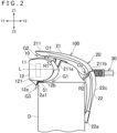
- FIG. 2 is a side elevational view depicting a state in which the camera unit according to the present embodiment is attached to the upper edge of the display device.
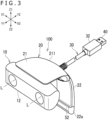
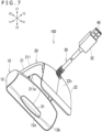
- FIG. 3 is a perspective view of the camera unit according to the present embodiment as viewed obliquely from above and front.
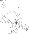
- FIG. 4 is a perspective view of the camera unit according to the present embodiment as viewed obliquely from above and rear.
- FIG. 5 is a top plan view depicting a state in which the camera unit according to the present embodiment is attached to the upper edge of the display device.
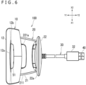
- FIG. 6 is a bottom plan view of the camera unit according to the present embodiment as viewed from below.
- FIG. 7 is a perspective view of the camera unit according to the present embodiment as viewed obliquely from rear and below.
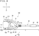
- FIG. 8 is a side elevational view depicting a state in which a second arm portion is positioned in a closed position in the camera unit according to the present embodiment.
- FIG. 9 is a sectional view depicting a cut face where the camera unit is cut along a IX-IX cut line of FIG. 5 .
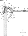
- FIG. 10 is a sectional view depicting a state in which the camera unit is attached to a display device that is thinner than the display device depicted in FIG. 9 .
- X1 and X2 indicated in FIG. 1 and so forth denote a rightward direction and a leftward direction, respectively
- Y1 and Y2 denote a forward direction and a rearward direction, respectively
- Z1 and Z2 denote an upward direction and a downward direction, respectively.
- a portion on the front side of each member described in the description of the present embodiment is referred to as a front portion
- a portion on the rear side is referred to as a rear portion
- a portion on the upper side is referred to as an upper portion
- a portion on the lower side is referred to as a lower portion.
- a face on the front side of each member described in the description of the present embodiment is referred to as a front face
- a face on the rear side is referred to as a rear face
- a face on the upper side is referred to as an upper face
- a face on the lower side is referred to as a lower face.
- the camera unit 100 is attached to an upper edge of a display device (for example, a television set or a display of a personal computer) D.
- a display device for example, a television set or a display of a personal computer
- the state of the camera unit 100 attached to the upper edge of the display device D is referred to also as use state.
- the camera unit 100 includes a camera main body 10, a stand 20, and a cable 30.
- the camera unit 100 is connected to an information processing apparatus (not depicted) such as a game device or a personal computer through the cable 30 and transmits image data acquired by a light receiving section 11 provided on the camera main body 10 to the information processing apparatus.
- the information processing apparatus generates a three-dimensional image on the basis of the image data acquired by two light receiving sections 11 provided on the camera main body 10.
- this is not restrictive, and only one light receiving section 11 may be provided, and the image generated by the information processing apparatus is a two-dimensional image.
- the camera main body 10 includes, as depicted in FIGS. 2 , 9 , and other figures, the light receiving section 11, a main body housing 12 that configures an exterior of the camera main body 10, and a circuit board 13 on which various electronic parts such as the light receiving section 11 are mounted.
- the main body housing 12 accommodates in the inside thereof the light receiving section 11, the circuit board 13, and other components.
- the main body housing 12 is supported by the stand 20 such that the orientation of the light receiving section 11 (optical axis L) can be adjusted in an upward and downward direction.
- the light receiving section 11 includes a lens module and a light receiving element and captures external light.
- the camera main body 10 includes two light receiving sections 11 positioned to be spaced from each other in a leftward and rightward direction. It is to be noted that the light receiving section 11 is schematically depicted in FIG. 2 and illustration of a detailed configuration thereof is omitted.
- the main body housing 12 has, at a lower portion 121 thereof in a use state of the camera unit 100, a lower face 12b that is to be placed on an upper face of the display device D. Further, the main body housing 12 has, at the lower portion 121 thereof in the use state of the camera unit 100, a protrusion 12a that projects downwardly. The protrusion 12a projects, in the use state of the camera unit 100, downwardly so as to be caught by a front face of the display device D in front of the lower face 12b.
- the camera main body 10 transmits sound data acquired by the microphone to the information processing apparatus through the cable 30.
- the cable 30 is provided so as to be connected to the camera main body 10 and extend rearwardly.
- the cable 30 is electrically connected at a front end portion 31 thereof (refer to FIGS. 9 and 10 ) to the circuit board 13 accommodated in the main body housing 12 of the camera main body 10.
- the cable 30 has a connector 40 provided at a rear end portion 32 thereof.
- the connector 40 is, for example, a USB (Universal Serial Bus) connector, it may otherwise be a connector of another type.
- the stand 20 includes a first arm portion 21 and a second arm portion 22.
- the first arm portion 21 includes an arm housing 211 that configures an exterior of the first arm portion 21.
- the arm housing 211 has a support portion 211a that supports the main body housing 12 for pivotal motion provided thereon such that the orientation of the optical axis L of the light receiving section 11 in the upward and downward direction can be adjusted.
- the support portion 211a supports the main body housing 12 for pivotal motion around a pivotal motion center 01 extending in the leftward and rightward direction through a hinge (not depicted).
- the support portion 211a extends downwardly at a front portion of the first arm portion 21 and supports an upper portion of the main body housing 12 through the hinge.
- the support portion 211a is configured so as to suspend and support the main body housing 12. It is sufficient if the hinge used here is a torque hinge that can hold the camera main body 10 at an optional position. By pivoting the camera main body 10 in an R1 direction indicated in FIG. 2 around the pivotal motion center 01, the orientation of the optical axis L of the light receiving section 11 is adjusted.
- the support portion 211a extending downwardly from the first arm portion 21 is indicated in the present embodiment, this is not restrictive, and it is sufficient if a configuration in which at least an upper portion of the main body housing 12 is supported by the first arm portion 21 is adopted.
- the second arm portion 22 is attached for pivotal motion to the first arm portion 21 such that the distance thereof to the camera main body 10 can be adjusted.
- the second arm portion 22 is attached at an end portion thereof to a rear portion of the first arm portion 21 for pivotal motion around a pivotal motion center 02 extending in the leftward and rightward direction through a hinge (not depicted). It is sufficient if the hinge used here is a torque hinge that can hold the second arm portion 22 at an optional position.
- the pivotal motion center 02 is disposed rearwardly and downwardly with respect to the pivotal motion center 01. It is to be noted that, although the pivotal motion center 01 and the pivotal motion center 02 do not physically appear on the appearance of the camera unit 100, they are depicted in FIGS. 2 and 5 in order to facilitate movements of the associated portions.
- the second arm portion 22 moves between a closed position and an open position by pivotally moving in an R2 direction depicted in FIG. 2 around the pivotal motion center 02.
- the closed position is a position at which the second arm portion 22 is positioned in the proximity of the camera main body 10
- the open position is a position in which the second arm portion 22 is spaced away from the camera main body 10.
- FIG. 2 depicts a state in which the second arm portion 22 is positioned at the open position.
- FIG. 8 depicts a state in which the second arm portion 22 is positioned at the closed position.
- part of the inside of the arm housing 211 of the first arm portion 21 forms a cavity C.
- part of the cable 30 is accommodated.
- an opening OP is formed in the rear portion 211b of the arm housing 211 so as to be directed rearwardly.
- the cable 30 extends rearwardly through the inside of the main body housing 12 and the first arm portion 21 and is exposed from the opening OP of the arm housing 211 and then extends rearwardly further.
- a portion of the cable 30 on the front side with respect to the opening OP is accommodated in the main body housing 12 and the arm housing 211 and cannot be viewed from the outside.
- a cutout 22b is formed at the end portion of the second arm portion 22 such that the opening OP of the arm housing 211 and the second arm portion 22 do not overlap with each other. Consequently, the cable 30 is avoided from interfering with the second arm portion 22.
- the camera unit 100 is used in such a manner that the display device D is sandwiched in a forward and rearward direction by the protrusion 12a provided on the main body housing 12 and a tip portion 22a of the second arm portion 22 as depicted in FIG. 2 and so forth.
- the protrusion 12a is caught by a front face of the display device D in the use state.
- the camera unit 100 attached to the upper edge of the display device D is suppressed from being displaced rearwardly.
- the protrusion 12a is provided at a front portion of the main body housing 12. Therefore, in the use state, a portion of the main body housing 12 in the rear of the protrusion 12a, namely, the lower face 12b of the main body housing 12, can be placed on the upper face of the display device D. Since the main body housing 12 can be placed directly on the upper face of the display device D in this manner, the posture of the camera unit 100 in the use state is stabilized. Further, since the main body housing 12 can be placed directly on the upper face of the display device D, the camera unit 100 can be used in a state in which the light receiving section 11 is positioned close to the screen of the display device D in the upward and downward direction. Therefore, a user who is in front of the display device D can be recognized easily by the camera.
- the second arm portion 22 contacts, at the tip portion 22a thereof, with a rear face of the display device D. Consequently, the camera unit 100 attached to the upper edge of the display device D is prevented from dropping rearwardly, and the posture of the camera unit 100 is stabilized.
- the second arm portion 22 takes the open position. It is sufficient if the open position of the second arm portion 22 is adjusted according to the width (thickness) of the display device D in the forward and rearward direction.
- FIG. 9 depicts a state in which the camera unit 100 is attached to the display device D that has a comparatively great width in the forward and rearward direction.
- the open position of the second arm portion 22 is a position in which the tip portion 22a thereof is spaced by a comparatively great distance from the camera main body 10.
- FIG. 10 depicts a state in which the camera unit 100 is attached to the display device D that has a comparatively small width (thickness) in the forward and rearward direction.
- the open position of the second arm portion 22 is a position in which the tip portion 22a thereof is positioned comparatively closer to the camera main body 10.
- the open position of the second arm portion 22 in a case where the camera unit 100 is attached to the display device D depicted in FIG. 10 is a position to which the second arm portion 22 is pivoted in an R2 direction (a clockwise direction) indicated in FIG. 10 from that in a case where the camera unit 100 is attached to the display device D depicted in FIG. 9 .
- the camera unit 100 not only may be used in a state in which it is attached to an upper edge of a display device but also may be placed and used on a table S such as, for example, a television stand.
- a table S such as, for example, a television stand.
- an outer face 22c of the second arm portion 22 (a lower face in the closed position) is placed on the table S in a state in which the second arm portion 22 is positioned at the closed position by pivoting the same in the R2 direction (the clockwise direction depicted in FIG. 8 ).
- the outer face 22c of the second arm portion 22 is shaped so as to include a rounded curved face from a design point of view.
- the outer face 22c (lower face in the closed position) of the second arm portion 22 includes a first holding point H1 for holding the posture of the second arm portion 22 and a curved face including a second holding point H2 for holding the posture of the second arm portion 22 in the rear with respect to the first holding point H1 in a case where it is viewed from the leftward or rightward direction of the second arm portion 22 as depicted in FIGS. 8 to 10 .
- the first holding point H1 and the second holding point H2 are portions that contact with the table S. In this manner, it is sufficient if the camera unit 100 is configured such that the posture thereof is kept by the two holding points as viewed in side elevation in the use state in which the second arm portion 22 is positioned at the closed position.
- first holding point H1 is a vertex of a protrusion that projects, for example, from part of the outer face 22c.
- second holding point H2 is part of a linear portion that extends in the leftward and rightward direction, for example, on the curved face of the second arm portion 22.
- the shape of the outer face 22c of the second arm portion 22 is not limited to a shape that includes a curved face and may be a shape including a flat face. In this case, by placing the flat face formed on the outer face 22c of the second arm portion 22 on the table S, the posture of the camera unit 100 can be stabilized.
- the lower face 12b of the main body housing 12 is a curved face that is inclined upwardly toward the rear. Therefore, in a state in which the camera unit 100 is attached to the display device D such that the optical axis L of the light receiving section 11 extends in parallel to the upper face of the display device D, a gap G1 is generated in the upward and downward direction between a lower portion of the main body housing 12 and the upper face of the display device D.
- a gap G2 is formed in the upward and downward direction between an upper portion of the main body housing 12 and a tip portion of the arm housing 211.
- the gap G2 is formed according to the length in the upward and downward direction of the support portion 211a that extends downwardly.
- Pivotal motion of the camera main body 10 in the clockwise direction in FIG. 2 is permitted according to each width of the gap G1 and the gap G2 in the upward and downward direction. In other words, it is permitted that the optical axis L of the light receiving section 11 is inclined in the upward direction in a state in which the camera unit 100 is attached to the display device D.
- the present embodiment is directed to an example in which the lower face 12b of the main body housing 12 includes a curved face, this is not restrictive, and the lower face 12b of the main body housing 12 may be configured so as to include a flat face that is inclined upwardly toward the rear. Also in such a structure as described, it is permitted that the optical axis L of the light receiving section 11 is inclined in the upward direction in a state in which the camera unit 100 is attached to the display device D.
- a rear face 12a1 of the protrusion 12a is inclined forwardly toward the downward. Therefore, in a state in which the camera unit 100 is attached to the display device D such that the optical axis L of the light receiving section 11 extends in parallel to the upper face of the display device D as depicted in FIG. 2 , a gap G3 is formed in the forward and rearward direction between the protrusion 12a and a front face of the display device D. Pivotal motion of the camera main body 10 in the counterclockwise direction in FIG. 2 is permitted according to the width of the gap G3 in the forward and rearward direction. In other words, in the state in which the camera unit 100 is attached to the display device D, it is permitted that the optical axis L of the light receiving section 11 is inclined in the downward direction.
- the camera unit 100 has a slip-proof member for causing friction provided at a portion thereof at which to contact with the display device D.
- a slip-proof member is provided on the lower face 12b of the main body housing 12 and an inner face of the tip portion 22a of the second arm portion 22.
- a slip-proof member 51 having a substantially L shape in side elevation view is provided over a range from the lower face 12b to the rear face 12a1 of the protrusion 12a of the main body housing 12.
- a belt-like slip-proof member 52 is provided on the inner face of the tip portion 22a of the second arm portion 22 so as to extend in the leftward and rightward direction.
- slip-proof members 51 and 52 are made of, for example, an elastomer resin and formed by two-color molding on the main body housing 12 and the second arm portion 22.
- the second arm portion 22 has a length that does not cause, in the state in which it is positioned at the closed position, interference with an end of the protrusion 12a in its projection direction. Further, it is sufficient if the tip portion 22a of the second arm portion 22 is shaped so as to follow the shape of the rear face 12a1 of the protrusion 12a in the state in which the second arm portion 22 is in the closed position. In particular, it is sufficient if the front face of the tip portion 22a in the closed position is inclined downwardly toward the front. By adopting such a configuration as described, a length of the second arm portion 22 can be secured.
- the width (thickness) of the display device D in the forward and rearward direction by sufficiently securing the length of the second arm portion 22, it is possible to attach the camera unit 100 to a greater number of types of the display device D. Further, by configuring the second arm portion 22 in such a way not to interfere with the tip of the protrusion 12a in the projection direction, namely, not to overlap with the protrusion 12a in the upward and downward direction, the size in the upward and downward direction of the camera unit 100 in the state in which the second arm portion 22 is positioned in the closed position can be minimized.
- the protrusion 12a is formed symmetrically in the leftward and rightward direction with respect to an axis of symmetry at a line that passes the center of the main body housing 12 in the leftward and rightward direction.
- the protrusion 12a may be shaped so as to extend from a left end portion to a right end portion of the main body housing 12.
- protrusions 12a may be formed in a spaced relationship from each other in the leftward and rightward direction at a left and portion and a right end portion of the main body housing 12.
- the camera unit 100 is configured such that it is attached to an upper edge of the display device D by sandwiching the display device D by the protrusion 12a provided on the camera main body 10 and the tip portion 22a of the second arm portion 22. Consequently, the configuration by which the camera unit 100 can be attached in a stable posture to the display device D and besides the orientation of the optical axis L of the light receiving section 11 can be adjusted can be implemented at two locations for pivotal motion (the pivotal motion center 01 and the pivotal motion center 02). In other words, the camera unit 100 that is simple in configuration and that includes a small number of parts can be provided.
- the cable 30 is connected at the front end portion 31 thereof to the camera main body 10 and extends rearwardly from the camera main body 10 so as to be accommodated in the arm housing 211 of the first arm portion 21 and be exposed from the opening OP formed at the rear portion 211b of the arm housing 211.
Landscapes
- Engineering & Computer Science (AREA)
- General Engineering & Computer Science (AREA)
- Mechanical Engineering (AREA)
- Physics & Mathematics (AREA)
- General Physics & Mathematics (AREA)
- Multimedia (AREA)
- Signal Processing (AREA)
- Studio Devices (AREA)
- Accessories Of Cameras (AREA)
- Two-Way Televisions, Distribution Of Moving Picture Or The Like (AREA)
Abstract
Description
- The present invention relates to a camera unit that is attached to an upper edge of a display device.
- PTL 1 discloses a camera unit that includes a camera and a stand and that is attached to an upper edge of a display device (for example, a television set or a display of a personal computer). The camera unit disclosed in PTL 1 adopts a structure that has three centers of rotation provided for mounting of the camera unit on a display device and for adjustment of the orientation of the camera.
- [PTL 1]
JP 2018-10117A - Such a camera unit as described above preferably has a more simplified configuration with which it can be attached to a display device.
- It is an object of the present invention to provide a camera unit that has a simplified configuration with which it can be attached to a display device.
- A camera unit for solving the problem described above includes a camera main body, and a stand configured to support the camera main body, in which the camera main body includes a light receiving section and a main body housing in which the light receiving section is accommodated, the stand includes a first arm portion configured to support the main body housing for pivotal motion such that an orientation in an upward and downward direction of an optical axis of the light receiving section is adjustable, and a second arm portion attached for pivotal motion to the first arm portion, and the main body hosing has a protrusion that projects downwardly at a lower portion of the camera unit in a use state of the camera unit.
-
- [
FIG. 1 ]
FIG. 1 is a perspective view depicting a state in which a camera unit according to the present embodiment is attached to an upper end of a display device. - [
FIG. 2 ]
FIG. 2 is a side elevational view depicting a state in which the camera unit according to the present embodiment is attached to the upper edge of the display device. - [
FIG. 3 ]
FIG. 3 is a perspective view of the camera unit according to the present embodiment as viewed obliquely from above and front. - [
FIG. 4 ]
FIG. 4 is a perspective view of the camera unit according to the present embodiment as viewed obliquely from above and rear. - [
FIG. 5 ]
FIG. 5 is a top plan view depicting a state in which the camera unit according to the present embodiment is attached to the upper edge of the display device. - [
FIG. 6 ]
FIG. 6 is a bottom plan view of the camera unit according to the present embodiment as viewed from below. - [
FIG. 7 ]
FIG. 7 is a perspective view of the camera unit according to the present embodiment as viewed obliquely from rear and below. - [
FIG. 8 ]
FIG. 8 is a side elevational view depicting a state in which a second arm portion is positioned in a closed position in the camera unit according to the present embodiment. - [
FIG. 9 ]
FIG. 9 is a sectional view depicting a cut face where the camera unit is cut along a IX-IX cut line ofFIG. 5 . - [
FIG. 10 ]
FIG. 10 is a sectional view depicting a state in which the camera unit is attached to a display device that is thinner than the display device depicted inFIG. 9 . - In the following, an embodiment of the present invention (hereinafter referred to as the present embodiment) is described with reference to the drawings.
-
FIG. 1 is a perspective view depicting a state in which a camera unit according to the present embodiment is attached to an upper end of a display device.FIG. 2 is a side elevational view depicting a state in which the camera unit according to the present embodiment is attached to the upper edge of the display device.FIG. 3 is a perspective view of the camera unit according to the present embodiment as viewed obliquely from above and front.FIG. 4 is a perspective view of the camera unit according to the present embodiment as viewed obliquely from above and rear.FIG. 5 is a top plan view depicting a state in which the camera unit according to the present embodiment is attached to the upper edge of the display device.FIG. 6 is a bottom plan view of the camera unit according to the present embodiment as viewed from below.FIG. 7 is a perspective view of the camera unit according to the present embodiment as viewed obliquely from rear and below.FIG. 8 is a side elevational view depicting a state in which a second arm portion is positioned in a closed position in the camera unit according to the present embodiment.FIG. 9 is a sectional view depicting a cut face where the camera unit is cut along a IX-IX cut line ofFIG. 5 .FIG. 10 is a sectional view depicting a state in which the camera unit is attached to a display device that is thinner than the display device depicted inFIG. 9 . - In the present specification, X1 and X2 indicated in
FIG. 1 and so forth denote a rightward direction and a leftward direction, respectively, Y1 and Y2 denote a forward direction and a rearward direction, respectively, and Z1 and Z2 denote an upward direction and a downward direction, respectively. The direction in which alight receiving section 11 hereinafter described is oriented, namely, the direction in which an optical axis L (refer toFIGS. 2 and3 ) of thelight receiving section 11 extends, is the forward direction. - Further, a portion on the front side of each member described in the description of the present embodiment is referred to as a front portion, a portion on the rear side is referred to as a rear portion, a portion on the upper side is referred to as an upper portion, and a portion on the lower side is referred to as a lower portion. Further, a face on the front side of each member described in the description of the present embodiment is referred to as a front face, a face on the rear side is referred to as a rear face, a face on the upper side is referred to as an upper face, and a face on the lower side is referred to as a lower face.
- As depicted in
FIG. 1 , thecamera unit 100 is attached to an upper edge of a display device (for example, a television set or a display of a personal computer) D. In the present specification, the state of thecamera unit 100 attached to the upper edge of the display device D is referred to also as use state. - The
camera unit 100 includes a cameramain body 10, astand 20, and acable 30. Thecamera unit 100 is connected to an information processing apparatus (not depicted) such as a game device or a personal computer through thecable 30 and transmits image data acquired by alight receiving section 11 provided on the cameramain body 10 to the information processing apparatus. The information processing apparatus generates a three-dimensional image on the basis of the image data acquired by twolight receiving sections 11 provided on the cameramain body 10. However, this is not restrictive, and only onelight receiving section 11 may be provided, and the image generated by the information processing apparatus is a two-dimensional image. - The camera
main body 10 includes, as depicted inFIGS. 2 ,9 , and other figures, thelight receiving section 11, amain body housing 12 that configures an exterior of the cameramain body 10, and acircuit board 13 on which various electronic parts such as thelight receiving section 11 are mounted. - The
main body housing 12 accommodates in the inside thereof thelight receiving section 11, thecircuit board 13, and other components. Themain body housing 12 is supported by thestand 20 such that the orientation of the light receiving section 11 (optical axis L) can be adjusted in an upward and downward direction. - The
light receiving section 11 includes a lens module and a light receiving element and captures external light. The cameramain body 10 includes two light receivingsections 11 positioned to be spaced from each other in a leftward and rightward direction. It is to be noted that thelight receiving section 11 is schematically depicted inFIG. 2 and illustration of a detailed configuration thereof is omitted. - The
main body housing 12 has, at alower portion 121 thereof in a use state of thecamera unit 100, alower face 12b that is to be placed on an upper face of the display device D. Further, themain body housing 12 has, at thelower portion 121 thereof in the use state of thecamera unit 100, aprotrusion 12a that projects downwardly. Theprotrusion 12a projects, in the use state of thecamera unit 100, downwardly so as to be caught by a front face of the display device D in front of thelower face 12b. - It is to be noted that, though not depicted, it is sufficient if it includes a microphone accommodated in the
main body housing 12. Further, it is sufficient if the cameramain body 10 transmits sound data acquired by the microphone to the information processing apparatus through thecable 30. - The
cable 30 is provided so as to be connected to the cameramain body 10 and extend rearwardly. In particular, thecable 30 is electrically connected at afront end portion 31 thereof (refer toFIGS. 9 and10 ) to thecircuit board 13 accommodated in themain body housing 12 of the cameramain body 10. Further, thecable 30 has aconnector 40 provided at arear end portion 32 thereof. Although theconnector 40 is, for example, a USB (Universal Serial Bus) connector, it may otherwise be a connector of another type. - The
stand 20 includes afirst arm portion 21 and asecond arm portion 22. - The
first arm portion 21 includes anarm housing 211 that configures an exterior of thefirst arm portion 21. Thearm housing 211 has asupport portion 211a that supports themain body housing 12 for pivotal motion provided thereon such that the orientation of the optical axis L of thelight receiving section 11 in the upward and downward direction can be adjusted. - The
support portion 211a supports themain body housing 12 for pivotal motion around apivotal motion center 01 extending in the leftward and rightward direction through a hinge (not depicted). Thesupport portion 211a extends downwardly at a front portion of thefirst arm portion 21 and supports an upper portion of themain body housing 12 through the hinge. In particular, thesupport portion 211a is configured so as to suspend and support themain body housing 12. It is sufficient if the hinge used here is a torque hinge that can hold the cameramain body 10 at an optional position. By pivoting the cameramain body 10 in an R1 direction indicated inFIG. 2 around thepivotal motion center 01, the orientation of the optical axis L of thelight receiving section 11 is adjusted. It is to be noted that, although thesupport portion 211a extending downwardly from thefirst arm portion 21 is indicated in the present embodiment, this is not restrictive, and it is sufficient if a configuration in which at least an upper portion of themain body housing 12 is supported by thefirst arm portion 21 is adopted. - The
second arm portion 22 is attached for pivotal motion to thefirst arm portion 21 such that the distance thereof to the cameramain body 10 can be adjusted. In the present embodiment, thesecond arm portion 22 is attached at an end portion thereof to a rear portion of thefirst arm portion 21 for pivotal motion around apivotal motion center 02 extending in the leftward and rightward direction through a hinge (not depicted). It is sufficient if the hinge used here is a torque hinge that can hold thesecond arm portion 22 at an optional position. In the present embodiment, thepivotal motion center 02 is disposed rearwardly and downwardly with respect to thepivotal motion center 01. It is to be noted that, although thepivotal motion center 01 and thepivotal motion center 02 do not physically appear on the appearance of thecamera unit 100, they are depicted inFIGS. 2 and5 in order to facilitate movements of the associated portions. - The
second arm portion 22 moves between a closed position and an open position by pivotally moving in an R2 direction depicted inFIG. 2 around thepivotal motion center 02. The closed position is a position at which thesecond arm portion 22 is positioned in the proximity of the cameramain body 10, and the open position is a position in which thesecond arm portion 22 is spaced away from the cameramain body 10.FIG. 2 depicts a state in which thesecond arm portion 22 is positioned at the open position.FIG. 8 depicts a state in which thesecond arm portion 22 is positioned at the closed position. - Further, as depicted in
FIGS. 9 and10 , part of the inside of thearm housing 211 of thefirst arm portion 21 forms a cavity C. In the cavity C, part of thecable 30 is accommodated. Further, as depicted inFIG. 4 and so forth, an opening OP is formed in therear portion 211b of thearm housing 211 so as to be directed rearwardly. Thecable 30 extends rearwardly through the inside of themain body housing 12 and thefirst arm portion 21 and is exposed from the opening OP of thearm housing 211 and then extends rearwardly further. In particular, a portion of thecable 30 on the front side with respect to the opening OP is accommodated in themain body housing 12 and thearm housing 211 and cannot be viewed from the outside. - Further, as depicted in
FIG. 4 , acutout 22b is formed at the end portion of thesecond arm portion 22 such that the opening OP of thearm housing 211 and thesecond arm portion 22 do not overlap with each other. Consequently, thecable 30 is avoided from interfering with thesecond arm portion 22. - The
camera unit 100 is used in such a manner that the display device D is sandwiched in a forward and rearward direction by theprotrusion 12a provided on themain body housing 12 and atip portion 22a of thesecond arm portion 22 as depicted inFIG. 2 and so forth. - The
protrusion 12a is caught by a front face of the display device D in the use state. By such a configuration as just described, thecamera unit 100 attached to the upper edge of the display device D is suppressed from being displaced rearwardly. - The
protrusion 12a is provided at a front portion of themain body housing 12. Therefore, in the use state, a portion of themain body housing 12 in the rear of theprotrusion 12a, namely, thelower face 12b of themain body housing 12, can be placed on the upper face of the display device D. Since themain body housing 12 can be placed directly on the upper face of the display device D in this manner, the posture of thecamera unit 100 in the use state is stabilized. Further, since themain body housing 12 can be placed directly on the upper face of the display device D, thecamera unit 100 can be used in a state in which thelight receiving section 11 is positioned close to the screen of the display device D in the upward and downward direction. Therefore, a user who is in front of the display device D can be recognized easily by the camera. - In the use state, the
second arm portion 22 contacts, at thetip portion 22a thereof, with a rear face of the display device D. Consequently, thecamera unit 100 attached to the upper edge of the display device D is prevented from dropping rearwardly, and the posture of thecamera unit 100 is stabilized. - In a use state, the
second arm portion 22 takes the open position. It is sufficient if the open position of thesecond arm portion 22 is adjusted according to the width (thickness) of the display device D in the forward and rearward direction.FIG. 9 depicts a state in which thecamera unit 100 is attached to the display device D that has a comparatively great width in the forward and rearward direction. When thecamera unit 100 is attached to the display device D that has a comparatively great width in the forward and rearward direction, the open position of thesecond arm portion 22 is a position in which thetip portion 22a thereof is spaced by a comparatively great distance from the cameramain body 10. -
FIG. 10 depicts a state in which thecamera unit 100 is attached to the display device D that has a comparatively small width (thickness) in the forward and rearward direction. When thecamera unit 100 is attached to the display device D that has a comparatively small width in the forward and rearward direction, the open position of thesecond arm portion 22 is a position in which thetip portion 22a thereof is positioned comparatively closer to the cameramain body 10. In particular, the open position of thesecond arm portion 22 in a case where thecamera unit 100 is attached to the display device D depicted inFIG. 10 is a position to which thesecond arm portion 22 is pivoted in an R2 direction (a clockwise direction) indicated inFIG. 10 from that in a case where thecamera unit 100 is attached to the display device D depicted inFIG. 9 . - It is to be noted that the
camera unit 100 not only may be used in a state in which it is attached to an upper edge of a display device but also may be placed and used on a table S such as, for example, a television stand. In this case, it is sufficient if, as depicted inFIG. 8 , anouter face 22c of the second arm portion 22 (a lower face in the closed position) is placed on the table S in a state in which thesecond arm portion 22 is positioned at the closed position by pivoting the same in the R2 direction (the clockwise direction depicted inFIG. 8 ). It is to be noted that, in the present embodiment, theouter face 22c of thesecond arm portion 22 is shaped so as to include a rounded curved face from a design point of view. Further, theouter face 22c (lower face in the closed position) of thesecond arm portion 22 includes a first holding point H1 for holding the posture of thesecond arm portion 22 and a curved face including a second holding point H2 for holding the posture of thesecond arm portion 22 in the rear with respect to the first holding point H1 in a case where it is viewed from the leftward or rightward direction of thesecond arm portion 22 as depicted inFIGS. 8 to 10 . The first holding point H1 and the second holding point H2 are portions that contact with the table S. In this manner, it is sufficient if thecamera unit 100 is configured such that the posture thereof is kept by the two holding points as viewed in side elevation in the use state in which thesecond arm portion 22 is positioned at the closed position. It is sufficient if the first holding point H1 is a vertex of a protrusion that projects, for example, from part of theouter face 22c. Further, it is sufficient if the second holding point H2 is part of a linear portion that extends in the leftward and rightward direction, for example, on the curved face of thesecond arm portion 22. By such a configuration as described above, it is possible to adopt a curved face shape for theouter face 22c of thesecond arm portion 22 and bring thesecond arm portion 22 to the closed position to stabilize the posture of thecamera unit 100 in the state in which thecamera unit 100 is placed on the table S. It is to be noted that the shape of theouter face 22c of thesecond arm portion 22 is not limited to a shape that includes a curved face and may be a shape including a flat face. In this case, by placing the flat face formed on theouter face 22c of thesecond arm portion 22 on the table S, the posture of thecamera unit 100 can be stabilized. - The
lower face 12b of themain body housing 12 is a curved face that is inclined upwardly toward the rear. Therefore, in a state in which thecamera unit 100 is attached to the display device D such that the optical axis L of thelight receiving section 11 extends in parallel to the upper face of the display device D, a gap G1 is generated in the upward and downward direction between a lower portion of themain body housing 12 and the upper face of the display device D. - Further, as depicted in
FIG. 2 , in a state in which thecamera unit 100 is attached to the display device D in such a manner that the optical axis L of thelight receiving section 11 extends in parallel to the upper face of the display device D, a gap G2 is formed in the upward and downward direction between an upper portion of themain body housing 12 and a tip portion of thearm housing 211. The gap G2 is formed according to the length in the upward and downward direction of thesupport portion 211a that extends downwardly. - Pivotal motion of the camera
main body 10 in the clockwise direction inFIG. 2 is permitted according to each width of the gap G1 and the gap G2 in the upward and downward direction. In other words, it is permitted that the optical axis L of thelight receiving section 11 is inclined in the upward direction in a state in which thecamera unit 100 is attached to the display device D. - It is to be noted that, while the present embodiment is directed to an example in which the
lower face 12b of themain body housing 12 includes a curved face, this is not restrictive, and thelower face 12b of themain body housing 12 may be configured so as to include a flat face that is inclined upwardly toward the rear. Also in such a structure as described, it is permitted that the optical axis L of thelight receiving section 11 is inclined in the upward direction in a state in which thecamera unit 100 is attached to the display device D. - Further, a rear face 12a1 of the
protrusion 12a is inclined forwardly toward the downward. Therefore, in a state in which thecamera unit 100 is attached to the display device D such that the optical axis L of thelight receiving section 11 extends in parallel to the upper face of the display device D as depicted inFIG. 2 , a gap G3 is formed in the forward and rearward direction between theprotrusion 12a and a front face of the display device D. Pivotal motion of the cameramain body 10 in the counterclockwise direction inFIG. 2 is permitted according to the width of the gap G3 in the forward and rearward direction. In other words, in the state in which thecamera unit 100 is attached to the display device D, it is permitted that the optical axis L of thelight receiving section 11 is inclined in the downward direction. - Further, it is sufficient if the
camera unit 100 has a slip-proof member for causing friction provided at a portion thereof at which to contact with the display device D. In particular, it is sufficient if a slip-proof member is provided on thelower face 12b of themain body housing 12 and an inner face of thetip portion 22a of thesecond arm portion 22. - In the present embodiment, as depicted in
FIGS. 2 and7 , a slip-proof member 51 having a substantially L shape in side elevation view is provided over a range from thelower face 12b to the rear face 12a1 of theprotrusion 12a of themain body housing 12. Further, as depicted inFIG. 3 , a belt-like slip-proof member 52 is provided on the inner face of thetip portion 22a of thesecond arm portion 22 so as to extend in the leftward and rightward direction. - It is to be noted that it is sufficient if the slip-
proof members main body housing 12 and thesecond arm portion 22. - Further, it is sufficient if, as depicted in
FIG. 8 , thesecond arm portion 22 has a length that does not cause, in the state in which it is positioned at the closed position, interference with an end of theprotrusion 12a in its projection direction. Further, it is sufficient if thetip portion 22a of thesecond arm portion 22 is shaped so as to follow the shape of the rear face 12a1 of theprotrusion 12a in the state in which thesecond arm portion 22 is in the closed position. In particular, it is sufficient if the front face of thetip portion 22a in the closed position is inclined downwardly toward the front. By adopting such a configuration as described, a length of thesecond arm portion 22 can be secured. Although various sizes are supposed for the width (thickness) of the display device D in the forward and rearward direction, by sufficiently securing the length of thesecond arm portion 22, it is possible to attach thecamera unit 100 to a greater number of types of the display device D. Further, by configuring thesecond arm portion 22 in such a way not to interfere with the tip of theprotrusion 12a in the projection direction, namely, not to overlap with theprotrusion 12a in the upward and downward direction, the size in the upward and downward direction of thecamera unit 100 in the state in which thesecond arm portion 22 is positioned in the closed position can be minimized. - It is to be noted that it is sufficient if the
protrusion 12a is formed symmetrically in the leftward and rightward direction with respect to an axis of symmetry at a line that passes the center of themain body housing 12 in the leftward and rightward direction. For example, theprotrusion 12a may be shaped so as to extend from a left end portion to a right end portion of themain body housing 12. Alternatively,protrusions 12a may be formed in a spaced relationship from each other in the leftward and rightward direction at a left and portion and a right end portion of themain body housing 12. - As described above, the
camera unit 100 according to the present embodiment is configured such that it is attached to an upper edge of the display device D by sandwiching the display device D by theprotrusion 12a provided on the cameramain body 10 and thetip portion 22a of thesecond arm portion 22. Consequently, the configuration by which thecamera unit 100 can be attached in a stable posture to the display device D and besides the orientation of the optical axis L of thelight receiving section 11 can be adjusted can be implemented at two locations for pivotal motion (thepivotal motion center 01 and the pivotal motion center 02). In other words, thecamera unit 100 that is simple in configuration and that includes a small number of parts can be provided. - Further, as described hereinabove, the
cable 30 is connected at thefront end portion 31 thereof to the cameramain body 10 and extends rearwardly from the cameramain body 10 so as to be accommodated in thearm housing 211 of thefirst arm portion 21 and be exposed from the opening OP formed at therear portion 211b of thearm housing 211. By adopting such a configuration as described, in the state in which thecamera unit 100 is attached to an upper edge of the display device D, thecable 30 does not interfere with the upper edge of the display device D. Therefore, thecable 30 is not affected by a load from the upper edge of the display device D. Further, since thecable 30 is exposed rearwardly from the rear face of the display device D, the visibility of thecable 30 drops and the appearance of thecamera unit 100 is improved as viewed from a user who is in front of the display device D to which thecamera unit 100 is attached.
Claims (12)
- A camera unit comprising:a camera main body; anda stand configured to support the camera main body; whereinthe camera main body includes a light receiving section and a main body housing in which the light receiving section is accommodated,the stand includes a first arm portion configured to support the main body housing for pivotal motion such that an orientation in an upward and downward direction of an optical axis of the light receiving section is adjustable, and a second arm portion attached for pivotal motion to the first arm portion, andthe main body hosing has a protrusion that projects downwardly at a lower portion of the camera unit in a use state of the camera unit.
- The camera unit according to claim 1, whereinthe first arm portion includes an arm housing having an opening at a rear portion thereof, andthe camera unit further comprises a cable that is electrically connected to a circuit board accommodated in the main body housing,that extends rearwardly passing the inside of the main body housing andthe arm housing and that is exposed from the opening.
- The camera unit according to claim 1 or 2, wherein
the main body housing is supported for pivotal motion at an upper portion thereof by the first arm portion. - The camera unit according to any one of claims 1 to 3, wherein
the second arm portion is attached to the first arm portion for pivotal motion between a closed position at which the second arm portion is positioned close to the camera main body and an open position at which the second arm portion is spaced away from the camera main body. - The camera unit according to claim 4, wherein
the protrusion is provided at a position at which the protrusion does not interfere with the second arm portion in a state in which the second arm portion is positioned at the closed position. - The camera unit according to claim 4 or 5, wherein
a lower face of the second arm portion in the state in which the second arm portion is at the closed position includes a first holding point for holding a posture of the second arm portion and a curved face that includes a second holding point for holding a posture of the second arm portion in the rear with respect to the first holding point, as viewed from a leftward and rightward direction. - The camera unit according to any one of claims 1 to 6, wherein
a rear face of the protrusion is inclined forwardly toward the downward. - The camera unit according to any one of claims 1 to 7, wherein
a lower face of the main body housing is inclined upwardly toward the rear. - The camera unit according to any one of claims 1 to 8, wherein
the main body housing has a slip-proof member on a lower face thereof. - The camera unit according to claim 9, wherein
the slip-proof member is provided over a range from the lower face of the main body housing to the rear face of the protrusion. - The camera unit according to any one of claims 1 to 10, wherein
a slip-proof member is provided on an inner face of a tip portion of the second arm portion. - The camera unit according to any one of claims 1 to 11, wherein
the protrusion is provided projecting downwardly so as to be caught by a front face of a display device in the use state of the camera unit.
Applications Claiming Priority (2)
| Application Number | Priority Date | Filing Date | Title |
|---|---|---|---|
| US202063031622P | 2020-05-29 | 2020-05-29 | |
| PCT/JP2021/019980 WO2021241633A1 (en) | 2020-05-29 | 2021-05-26 | Camera unit |
Publications (3)
| Publication Number | Publication Date |
|---|---|
| EP4160310A1 true EP4160310A1 (en) | 2023-04-05 |
| EP4160310A4 EP4160310A4 (en) | 2024-06-26 |
| EP4160310B1 EP4160310B1 (en) | 2025-10-29 |
Family
ID=78704485
Family Applications (1)
| Application Number | Title | Priority Date | Filing Date |
|---|---|---|---|
| EP21814286.7A Active EP4160310B1 (en) | 2020-05-29 | 2021-05-26 | Camera unit |
Country Status (5)
| Country | Link |
|---|---|
| US (1) | US11553114B2 (en) |
| EP (1) | EP4160310B1 (en) |
| JP (1) | JP7556955B2 (en) |
| CN (1) | CN115668053A (en) |
| WO (1) | WO2021241633A1 (en) |
Families Citing this family (2)
| Publication number | Priority date | Publication date | Assignee | Title |
|---|---|---|---|---|
| USD1038925S1 (en) * | 2022-05-26 | 2024-08-13 | Yealink (Xiamen) Network Technology Co., Ltd. | All-in-one communication device |
| USD1038125S1 (en) * | 2022-09-16 | 2024-08-06 | Jupiter Systems, Inc. | Display screen |
Family Cites Families (17)
| Publication number | Priority date | Publication date | Assignee | Title |
|---|---|---|---|---|
| JPH10136241A (en) | 1996-10-30 | 1998-05-22 | Canon Inc | Camera fixing device |
| JPH10191137A (en) | 1996-12-27 | 1998-07-21 | Fukudai Jitsugyo Kk | Television camera and personal computer |
| US5855343A (en) * | 1997-03-07 | 1999-01-05 | Irez Research, Corporation | Camera clip |
| JP3833837B2 (en) | 1998-11-09 | 2006-10-18 | シャープ株式会社 | Video camera |
| CA2288451A1 (en) * | 1998-11-09 | 2000-05-09 | Seiji Muramoto | Video camera |
| JP2004112731A (en) * | 2002-07-26 | 2004-04-08 | Sumitomo Electric Ind Ltd | Imaging device, terminal device, and interactive interactive system |
| US7048454B2 (en) * | 2004-05-28 | 2006-05-23 | Creative Technology Ltd | Three way video camera base |
| JP2006172361A (en) * | 2004-12-20 | 2006-06-29 | Sony Corp | Electronic equipment fittings |
| US7931243B2 (en) * | 2006-04-07 | 2011-04-26 | Logitech Europe S.A. | Speaker with monitor mountable stand |
| US20090103913A1 (en) * | 2007-10-19 | 2009-04-23 | Chih-Ming Huang | Multifunctional supporting frame for a web camera |
| JP2010147535A (en) | 2008-12-16 | 2010-07-01 | Masaharu Tamatsu | Camera installation device |
| JP2012054813A (en) * | 2010-09-02 | 2012-03-15 | Ricoh Co Ltd | Casing of conference apparatus, and conference apparatus |
| SG182032A1 (en) * | 2011-01-03 | 2012-07-30 | Creative Tech Ltd | An assembly, a support and a method for carrying a peripheral device |
| JP2013001300A (en) | 2011-06-20 | 2013-01-07 | Nifco Inc | Clip |
| US9217911B1 (en) * | 2015-02-24 | 2015-12-22 | Sorenson Communications, Inc. | Camera assembly having a camera support system with a biased hinge and related methods |
| JP6700131B2 (en) * | 2016-07-13 | 2020-05-27 | 株式会社ソニー・インタラクティブエンタテインメント | Camera, stand, and camera unit including them |
| US10582094B2 (en) * | 2016-09-21 | 2020-03-03 | Gopro, Inc. | Camera mount stand and cover |
-
2021
- 2021-05-17 US US17/321,951 patent/US11553114B2/en active Active
- 2021-05-26 EP EP21814286.7A patent/EP4160310B1/en active Active
- 2021-05-26 WO PCT/JP2021/019980 patent/WO2021241633A1/en not_active Ceased
- 2021-05-26 CN CN202180036746.6A patent/CN115668053A/en active Pending
- 2021-05-26 JP JP2022526612A patent/JP7556955B2/en active Active
Also Published As
| Publication number | Publication date |
|---|---|
| JPWO2021241633A1 (en) | 2021-12-02 |
| US11553114B2 (en) | 2023-01-10 |
| WO2021241633A1 (en) | 2021-12-02 |
| US20210377426A1 (en) | 2021-12-02 |
| EP4160310A4 (en) | 2024-06-26 |
| JP7556955B2 (en) | 2024-09-26 |
| CN115668053A (en) | 2023-01-31 |
| EP4160310B1 (en) | 2025-10-29 |
Similar Documents
| Publication | Publication Date | Title |
|---|---|---|
| US20240235109A1 (en) | Eyewear having selectively exposable feature | |
| US10514559B1 (en) | Eyewear having linkage assembly between a temple and a frame | |
| US6462781B1 (en) | Foldable teleconferencing camera | |
| EP3439322B1 (en) | Audio output assembly for a head-mounted display | |
| KR101977433B1 (en) | Wearable device with input and output structures | |
| US9261919B2 (en) | Dock with compliant connector mount | |
| EP4160310B1 (en) | Camera unit | |
| US11619821B2 (en) | Head-mounted display | |
| JP2015509209A (en) | Wearable device with input / output mechanism | |
| CN219202077U (en) | Elastic damping member, temple assembly, wearing mechanism, glasses and head-mounted equipment | |
| US20090115687A1 (en) | Video display device | |
| EP4217786B1 (en) | Head-mountable device with connectable accessories | |
| US12047109B2 (en) | Electronic device including antenna structure | |
| US11226656B2 (en) | Computer | |
| US10184606B2 (en) | Camera, stand, and camera unit having camera and stand | |
| US20170090200A1 (en) | Display device and head mounted display | |
| EP2472348A2 (en) | Information processing apparatus | |
| KR20190050613A (en) | Head mounting device | |
| US10496185B2 (en) | Input device and display device including the same | |
| US10809597B2 (en) | Imaging device | |
| CN112433366B (en) | Intelligent glasses | |
| CN112684603A (en) | Intelligent glasses | |
| US20250224624A1 (en) | Hyperextendable friction hinge | |
| KR102966647B1 (en) | Wearable electronic device including light emitting unit | |
| US11762210B1 (en) | Management of elongated structures for head mounted device |
Legal Events
| Date | Code | Title | Description |
|---|---|---|---|
| STAA | Information on the status of an ep patent application or granted ep patent |
Free format text: STATUS: THE INTERNATIONAL PUBLICATION HAS BEEN MADE |
|
| PUAI | Public reference made under article 153(3) epc to a published international application that has entered the european phase |
Free format text: ORIGINAL CODE: 0009012 |
|
| STAA | Information on the status of an ep patent application or granted ep patent |
Free format text: STATUS: REQUEST FOR EXAMINATION WAS MADE |
|
| 17P | Request for examination filed |
Effective date: 20221006 |
|
| AK | Designated contracting states |
Kind code of ref document: A1 Designated state(s): AL AT BE BG CH CY CZ DE DK EE ES FI FR GB GR HR HU IE IS IT LI LT LU LV MC MK MT NL NO PL PT RO RS SE SI SK SM TR |
|
| DAV | Request for validation of the european patent (deleted) | ||
| DAX | Request for extension of the european patent (deleted) | ||
| A4 | Supplementary search report drawn up and despatched |
Effective date: 20240524 |
|
| RIC1 | Information provided on ipc code assigned before grant |
Ipc: H04N 23/51 20230101ALI20240517BHEP Ipc: H04N 7/10 20060101ALI20240517BHEP Ipc: G03B 17/56 20210101AFI20240517BHEP |
|
| GRAP | Despatch of communication of intention to grant a patent |
Free format text: ORIGINAL CODE: EPIDOSNIGR1 |
|
| STAA | Information on the status of an ep patent application or granted ep patent |
Free format text: STATUS: GRANT OF PATENT IS INTENDED |
|
| INTG | Intention to grant announced |
Effective date: 20250702 |
|
| GRAS | Grant fee paid |
Free format text: ORIGINAL CODE: EPIDOSNIGR3 |
|
| GRAA | (expected) grant |
Free format text: ORIGINAL CODE: 0009210 |
|
| STAA | Information on the status of an ep patent application or granted ep patent |
Free format text: STATUS: THE PATENT HAS BEEN GRANTED |
|
| AK | Designated contracting states |
Kind code of ref document: B1 Designated state(s): AL AT BE BG CH CY CZ DE DK EE ES FI FR GB GR HR HU IE IS IT LI LT LU LV MC MK MT NL NO PL PT RO RS SE SI SK SM TR |
|
| REG | Reference to a national code |
Ref country code: CH Ref legal event code: F10 Free format text: ST27 STATUS EVENT CODE: U-0-0-F10-F00 (AS PROVIDED BY THE NATIONAL OFFICE) Effective date: 20251029 Ref country code: GB Ref legal event code: FG4D |
|
| REG | Reference to a national code |
Ref country code: DE Ref legal event code: R096 Ref document number: 602021041419 Country of ref document: DE |
|
| P01 | Opt-out of the competence of the unified patent court (upc) registered |
Free format text: CASE NUMBER: UPC_APP_9577_4160310/2025 Effective date: 20251010 |
|
| REG | Reference to a national code |
Ref country code: IE Ref legal event code: FG4D |
|
| REG | Reference to a national code |
Ref country code: NL Ref legal event code: FP |
|
| PG25 | Lapsed in a contracting state [announced via postgrant information from national office to epo] |
Ref country code: ES Free format text: LAPSE BECAUSE OF FAILURE TO SUBMIT A TRANSLATION OF THE DESCRIPTION OR TO PAY THE FEE WITHIN THE PRESCRIBED TIME-LIMIT Effective date: 20251029 |
|
| REG | Reference to a national code |
Ref country code: LT Ref legal event code: MG9D |
|
| PG25 | Lapsed in a contracting state [announced via postgrant information from national office to epo] |
Ref country code: NO Free format text: LAPSE BECAUSE OF FAILURE TO SUBMIT A TRANSLATION OF THE DESCRIPTION OR TO PAY THE FEE WITHIN THE PRESCRIBED TIME-LIMIT Effective date: 20260129 |
|
| PG25 | Lapsed in a contracting state [announced via postgrant information from national office to epo] |
Ref country code: HR Free format text: LAPSE BECAUSE OF FAILURE TO SUBMIT A TRANSLATION OF THE DESCRIPTION OR TO PAY THE FEE WITHIN THE PRESCRIBED TIME-LIMIT Effective date: 20251029 Ref country code: FI Free format text: LAPSE BECAUSE OF FAILURE TO SUBMIT A TRANSLATION OF THE DESCRIPTION OR TO PAY THE FEE WITHIN THE PRESCRIBED TIME-LIMIT Effective date: 20251029 Ref country code: AT Free format text: LAPSE BECAUSE OF FAILURE TO SUBMIT A TRANSLATION OF THE DESCRIPTION OR TO PAY THE FEE WITHIN THE PRESCRIBED TIME-LIMIT Effective date: 20251029 |
|
| REG | Reference to a national code |
Ref country code: AT Ref legal event code: MK05 Ref document number: 1852228 Country of ref document: AT Kind code of ref document: T Effective date: 20251029 |
|
| PG25 | Lapsed in a contracting state [announced via postgrant information from national office to epo] |
Ref country code: RS Free format text: LAPSE BECAUSE OF FAILURE TO SUBMIT A TRANSLATION OF THE DESCRIPTION OR TO PAY THE FEE WITHIN THE PRESCRIBED TIME-LIMIT Effective date: 20260129 |
|
| PG25 | Lapsed in a contracting state [announced via postgrant information from national office to epo] |
Ref country code: IS Free format text: LAPSE BECAUSE OF FAILURE TO SUBMIT A TRANSLATION OF THE DESCRIPTION OR TO PAY THE FEE WITHIN THE PRESCRIBED TIME-LIMIT Effective date: 20260228 |
|
| PG25 | Lapsed in a contracting state [announced via postgrant information from national office to epo] |
Ref country code: PT Free format text: LAPSE BECAUSE OF FAILURE TO SUBMIT A TRANSLATION OF THE DESCRIPTION OR TO PAY THE FEE WITHIN THE PRESCRIBED TIME-LIMIT Effective date: 20260302 |
|
| PG25 | Lapsed in a contracting state [announced via postgrant information from national office to epo] |
Ref country code: PL Free format text: LAPSE BECAUSE OF FAILURE TO SUBMIT A TRANSLATION OF THE DESCRIPTION OR TO PAY THE FEE WITHIN THE PRESCRIBED TIME-LIMIT Effective date: 20251029 |
|
| PG25 | Lapsed in a contracting state [announced via postgrant information from national office to epo] |
Ref country code: LV Free format text: LAPSE BECAUSE OF FAILURE TO SUBMIT A TRANSLATION OF THE DESCRIPTION OR TO PAY THE FEE WITHIN THE PRESCRIBED TIME-LIMIT Effective date: 20251029 |
|
| PG25 | Lapsed in a contracting state [announced via postgrant information from national office to epo] |
Ref country code: BG Free format text: LAPSE BECAUSE OF FAILURE TO SUBMIT A TRANSLATION OF THE DESCRIPTION OR TO PAY THE FEE WITHIN THE PRESCRIBED TIME-LIMIT Effective date: 20251029 |