EP4160239A1 - Zelle für ein optisch gepumptes atommagnetgradiometer, ein optisch gepumptes atommagnetgradiometer und system mit dem gradiometer und mikroskopiesystem - Google Patents
Zelle für ein optisch gepumptes atommagnetgradiometer, ein optisch gepumptes atommagnetgradiometer und system mit dem gradiometer und mikroskopiesystem Download PDFInfo
- Publication number
- EP4160239A1 EP4160239A1 EP21382888.2A EP21382888A EP4160239A1 EP 4160239 A1 EP4160239 A1 EP 4160239A1 EP 21382888 A EP21382888 A EP 21382888A EP 4160239 A1 EP4160239 A1 EP 4160239A1
- Authority
- EP
- European Patent Office
- Prior art keywords
- cell
- probe light
- pump
- probe
- confining
- Prior art date
- Legal status (The legal status is an assumption and is not a legal conclusion. Google has not performed a legal analysis and makes no representation as to the accuracy of the status listed.)
- Pending
Links
Images



Classifications
-
- G—PHYSICS
- G01—MEASURING; TESTING
- G01R—MEASURING ELECTRIC VARIABLES; MEASURING MAGNETIC VARIABLES
- G01R33/00—Arrangements or instruments for measuring magnetic variables
- G01R33/02—Measuring direction or magnitude of magnetic fields or magnetic flux
- G01R33/032—Measuring direction or magnitude of magnetic fields or magnetic flux using magneto-optic devices, e.g. Faraday or Cotton-Mouton effect
-
- G—PHYSICS
- G01—MEASURING; TESTING
- G01R—MEASURING ELECTRIC VARIABLES; MEASURING MAGNETIC VARIABLES
- G01R33/00—Arrangements or instruments for measuring magnetic variables
- G01R33/20—Arrangements or instruments for measuring magnetic variables involving magnetic resonance
- G01R33/24—Arrangements or instruments for measuring magnetic variables involving magnetic resonance for measuring direction or magnitude of magnetic fields or magnetic flux
- G01R33/26—Arrangements or instruments for measuring magnetic variables involving magnetic resonance for measuring direction or magnitude of magnetic fields or magnetic flux using optical pumping
-
- G—PHYSICS
- G01—MEASURING; TESTING
- G01R—MEASURING ELECTRIC VARIABLES; MEASURING MAGNETIC VARIABLES
- G01R33/00—Arrangements or instruments for measuring magnetic variables
- G01R33/02—Measuring direction or magnitude of magnetic fields or magnetic flux
- G01R33/022—Measuring gradient
Definitions
- the present invention generally relates, in a first aspect, to a cell for an optically-pumped atomic magnetic gradiometer, and particularly to a multi-chamber cell.
- a second aspect of the present invention relates to an optically-pumped atomic magnetic gradiometer including the cell of the first aspect.
- a third aspect of the present invention relates to a system, comprising the gradiometer of the second aspect and a microscopy system.
- a cell for an optically-pumped atomic magnetic gradiometer including the features defined in the preamble of claim 1 Is known in the prior art, i.e., a cell comprising a confining chamber containing alkali atoms, wherein the confining chamber is configured to receive a co-propagating pump and probe light beam, including pump light polarized to spin polarize the alkali atoms.
- the cell described in that paper includes only a single confining chamber, having a first measuring zone which is traversed by a co-propagating pump and probe light beam entering from a front face of the cell and exiting through a back side of the cell, and a second measuring zone which is traversed by a co-propagating pump, entering from the same front face, and probe light beam entering from the back face of the cell and exiting through its front side, and that is formed by the combination of the probe light beam that has exited the first zone, and which has been retro reflected, and a further pump beam.
- the first and second measuring zones of the cell are spaced 4 cm along the long axis of the cell, while the cell has inner dimensions 5 mm x 5 mm x 50 mm.
- a drawback of said paper is that the probe beam enters from the front side of the cell, in the first measuring zone, and from the back face of the cell, in the second measuring zone. This is not practical to get a magnetic sample close to the cell on one side, because both faces of the cell include pump/probe optics or optical detection stage.
- the present invention relates, in a first aspect, to a cell for an optically-pumped atomic magnetic gradiometer, comprising a confining chamber containing alkali atoms, wherein the confining chamber is configured to receive a co-propagating and pump and probe light beam, including pump light polarized to spin polarize the alkali atoms.
- the above-mentioned confining chamber is a first confining chamber
- the cell comprises at least a second confining chamber containing alkali atoms, distanced from the first confining chamber, and which is also configured to receive a co-propagating and pump and probe light beam.
- each of the two measuring zones used to perform gradiometric measurements is provided by a respective confining chamber.
- the first and second confining chambers are configured either to receive two respective co-propagating and pump and probe light beams from the same side of the cell but striking at different regions thereof at the same time or to receive the same co-propagating pump and probe beam from the same side of the cell but striking at different regions at different times.
- the first and second confining chambers are coplanar, and distanced from each other from 100 ⁇ m to 10 mm, along a plane occupied by both the first and the second confining chamber.
- the cell of the first aspect of the present invention further comprises, for an embodiment, top and bottom walls arranged at and covering opposite ends of at least the first and second confining chambers, each of said first and second walls having a partial reflectivity for said pump and probe lights, to make an optical cavity for probe light
- top and bottom walls arranged at and covering opposite ends of at least the first and second confining chambers, each of said first and second walls having a partial reflectivity for said pump and probe lights, to make an optical cavity for probe light
- each of the top and bottom walls has different partial reflectivities for the pump and probe lights, above 90% for the probe light and below 50% for the pump light.
- each of the top and bottom walls has a thickness below 1 mm.
- the first and second confining chambers have a confinement height below 1 mm, therefore constituting a microcell, as the atomic interaction length is below 1 mm.
- each of the first and second walls has a thickness ranging between 100 ⁇ m and 3 mm. This will change the free spectral range of the optical cavity, but not the atomic interaction length, the confinement height which is the important parameter to say the cell is a microcell.
- the first and second confining chambers further contain a buffer gas at a pressure above 3 bar and up to 20 bar, to prevent atomic depolarizing collisions.
- the at least first and second confining chambers comprise at least two physics chambers
- the cell comprising further confining chambers including a reservoir and connecting channels fluidically communicating the at least two physics chambers with the reservoir.
- the at least two physics chambers have a width (when, for example, rectangular) or diameter (when circular) ranging from 100 ⁇ m to 10 mm, preferably from 400 ⁇ m to 5 mm.
- the first, second and further confining chambers are laterally demarcated by intermediate partition and contour walls arranged between and bonded to the top and bottom walls, wherein the first, second and further confining chambers are gas-tight sealed from the environment by the intermediate partition and contour walls and top and bottom walls.
- each of the top and bottom walls comprises a respective structure that is transparent to the pump and probe lights, and a respective optical coating on an external face of each of the transparent structures, wherein the optical coatings provide the above-mentioned partial reflectivities, thus making the cell become an optical cavity cell. A higher sensitivity is obtained through these optical coatings.
- top and bottom walls could provide those reflectivities, not with an optical coating but with an inner structure of those walls.
- the outer surfaces of the top and bottom walls are planar, while for other embodiments they are machined with curvature to match a pseudo collimated Gaussian beam, which, for some embodiments, has a beam waist comparable to the sub-mm thickness of the interaction length.
- the present invention relates to an optically-pumped atomic magnetic gradiometer, comprising:
- both the first and second co-propagating probe and pump beams, or the same co-propagating pump and probe light beam enter each measuring zone from the front side of the cell.
- the optically-pumped atomic magnetic gradiometer operates according to a transmission detection mode, wherein the optically-pumped atomic magnetic gradiometer further comprises:
- the illumination means comprise pump and probe laser sources, and associated optics.
- the polarizing means of the first main embodiment of the optically-pumped atomic magnetic gradiometer of the second aspect of the present invention comprise any arrangement suitable to perform the above-mentioned linear polarization for the probe light and circularly polarization for the probe light, such as but not limited to a multi-order waveplate, a dichroic waveplate, or the polarization of pump and probe is fixed before they are combined on the same output mode of a dichroic mirror (instead of being fibre coupled) in free space.
- the bottom wall defines said front side of the cell and has a reflectivity for the probe light ranging between 90% and 99% and for the pump light below 50%, the latter preferably adjustable to get enough transmitted pump intensity to fully polarize the atomic ensemble, and the top wall has a reflectivity for the probe light ranging between 98% and, 99.9%, and either fully reflects the pump light or partially transmits it.
- These reflectivity values give a finesse of the optical cavity for the probe light ranging from 50 to 1000, preferably from 100 to 500.
- a filter is placed after the cell so that only probe light reaches the detectors of the measuring unit.
- the optically-pumped atomic magnetic gradiometer operates according to a reflection detection mode, further comprising:
- an interference filter is added to filter out the pump light at the detection stage, while detecting probe light only.
- the bottom wall defines the front side of the cell and has a reflectivity for the probe light ranging between 90% and 99% and for the pump light below 50%, the latter preferably adjustable to get enough transmitted pump intensity to fully polarize the atomic ensemble, and the top wall has a reflectivity for the probe light ranging between 90% and 99%, to almost fully reflect the pump light.
- a filter is placed before the detectors of the measuring unit so that only probe light reaches those detectors.
- the polarizing means of the second main embodiment of the optically-pumped atomic magnetic gradiometer of the second aspect of the present invention comprises any arrangement suitable to perform the above-mentioned linear polarization for the probe light and circularly polarization for the probe light, such as but not limited to a polarizing beam splitter and a quarter waveplate.
- the probe light is locked on resonance with the cell but detuned from atomic resonance of the alkali atoms, so that absorption of probe light is negligible, and the measurement is dispersive.
- the present invention further relates, in a third aspect, to a system comprising:
- the present invention relates to a method for fabricating the cell for an optically-pumped atomic magnetic gradiometer of the second aspect of the present invention, comprising providing its first and second confining chambers and filling the same with the alkali atoms, wherein the first and second confining chambers are configured to receive respective co-propagating pump and probe light beams, or the same co-propagating pump and probe beam, including pump light polarized to spin polarize the alkali atoms.
- a method like the one of the fourth aspect of the present invention, but for fabricating a cell for atomic sensing and metrology applications, is also disclosed in the present document, and could be object of a further invention.
- the method of the fourth aspect of the present invention further comprises providing and arranging top and bottom walls at opposite ends of at least the first and second confining chambers, such that said opposite ends are covered by the top and bottom walls, each of the first and second walls having a partial reflectivity for the pump and probe lights.
- the method of the fourth aspect of the present invention comprises sequentially performing the following steps:
- the at least first and second confining chambers have a confinement height below 1 mm, wherein:
- the method further comprises performing, after step d), a step of decomposing the alkali metal compound in alkali metal, constituting said alkali atoms, and a buffer gas at a pressure above 3 bar.
- the method comprises micro-pipetting an amount of the alkali metal compound, such as RbN 3 (rubidium azide), in aqueous solution higher than 1 microliter, higher than 3 microliters to get such a high pressure, up to 10 bar. Having such a high volume of the alkali metal compound allows to get high buffer gas pressure after chemical reaction. The activation occurs in the reservoir and then alkali atoms and buffer gas flow through the connecting channels up to the physics chambers.
- the method comprises fluidically connecting the reservoir to a gas line to back-filled the cell with the desired alkali vapour and buffer gas amount and then seal the cell with conventional glass-blowing technique.
- the alkali atoms of the filled alkali vapour and the filled buffer gas will flow through the connecting channels up to the physics chambers.
- the alkali metal compound is, for some embodiments, one or more of an azide, a solid-state dispenser, pure alkali metal or reaction between barium azide and alkali (Rb) chloride or mix of Rb salt and CaCl to get pure Rb.
- the step of decomposing the alkali metal compound is performed by UV irradiating the alkali metal compound through at least one of the structures of the top and bottom walls that is at least partially transmissive to UV radiation.
- the structures of the top and bottom walls are, for an embodiment, transparent to the pump and probe lights, and the method of the fourth aspect of the present invention further comprises, respective steps e) and f) of coating an external face of each of said transparent structures with a respective optical coating providing said partial reflectivities.
- steps e) and f) of coating an external face of each of said transparent structures with a respective optical coating providing said partial reflectivities.
- the method of the fourth aspect of the present invention comprises coating an external face of each of the transparent structures of the top and bottom walls with a respective optical coating, before they are anodically bonded at steps a) and d) respectively.
- Figure 2A and 2B illustrate the cavity cell of the first aspect of the present invention, for an embodiment for which the cavity cell 113 comprise three thin substrates or walls, W1, W2, W3: two glass substrates with optically coated outer surfaces and inner surfaces bonded to a middle wafer (such as a silicon wafer) which is etched with the desired geometry for atomic interaction (shown in Figure 2B ).
- W1, W2, W3 two glass substrates with optically coated outer surfaces and inner surfaces bonded to a middle wafer (such as a silicon wafer) which is etched with the desired geometry for atomic interaction
- Figure 2A are an exploded and assembled respective views of the cavity cell 113 formed by a top wall/substrate W1 and bottom wall/substrate W2 arranged at and covering opposite ends of several confining chambers, including physical cavities 101d, defined in a middle wafer which is etched so that the confining chambers are defined and laterally demarcated by intermediate partition and contour walls W3 (i.e., by the material of the wafer which has not been etched).
- FIG. 2A shows the intermediate partition and contour walls W3, the defined confining chambers and the bottom wall/substrate W2. This results in the so-called "preform" of the cavity cell of the first aspect of the invention.
- FIG. 2B different arrangements of confining chambers of the cavity cell 113 are shown, particularly, from left to right, a 4-, 9-, 20- and 40-physical cavities arrangement, fluidically communicated through connecting channels 101i-101k to a reservoir 101c, all of them being laterally demarcated by the intermediate partition and contour walls W3 and delimited at the top and bottom by the top W1 and bottom W2 walls/substrates respectively.
- the cavity diameter 101j ranges from 3.5 mm (4 cavities) down to 400 micron (40 cavities).
- the reservoir 101c can be round or squared with each side 101g/101h up to 10 mm.
- the outer dimensions 101f and 101e can range from few cm to tens of mm.
- the channels 101i-101k connecting the reservoir 101c with the round cavities 101d can have a width from hundreds of microns, e.g. 200 ⁇ m, down to tens of micron.
- a gradiometer operation mode is enabled by probing different physics cavities 101d with baseline 101L and 101m, ranging from 5 mm to hundreds of microns, in the two dimension respectively, with parallel beams or by probing the same physics chamber 101d.
- the same pump and probe beam strikes on different physics cavities at different times.
- the probing of multiple cavities e.g., 20 or 40 cavities, enables high-order gradiometer measurements with sub-mm spatial resolution.
- Some of the physics cavities 101d can be formed by a microchannel, shown in the 40 cavities Fig. 2B , with width 101n that ranges from tens to hundreds of microns.
- step f) is performed before step e).
- the outer surfaces reflectance for the probe light can range between 90% and 99.99%, depending on the desired trade-off between finesse and residual absorption as well as on the measurement method, in transmission or reflection.
- the pump transmittance is 50% or higher, a partial reflection can be a pro for full atomic polarization.
- the middle silicon wafer Wf, and thus the partition and contour walls W3 has sub-mm thickness L 2 , e.g., 100 or 200 ⁇ m, to enable sub-mm interaction volume and spatial resolution
- the bottom wall/substrate W2 also has sub-mm thickness L 2 , e.g. 200 ⁇ m, allowing for sub-mm stand-off distance from a sample.
- the input probe field Ein can be linearly polarized for detection in transmission or circularly polarized with ⁇ + or ⁇ - polarization for detection in reflection, while ET (ER) is the transmitted (reflected) electric field.
- the probe beam diameter D is twice the waist radius at the centre of the atomic interaction length L2.
- n is the atomic number density
- r e is the electron radius
- c is the speed of light
- f osc is the oscillation strength of the rubidium D 2 line
- D ⁇ ⁇ ⁇ 0 / ⁇ ⁇ ⁇ 0 2 + ⁇ 2 2 is a dispersion profile centered at the ⁇ 0 atomic resonance, e.g. the central D2 line, with buffer gas pressure broadened linewidth ⁇ .
- the atomic polarization induced displacement L2' ⁇ n ⁇ (t)L2 is measured by detecting the reflected intensity
- the cavity has the effect to enhance the error signal slope, as well as increasing carrier and sideband powers. All details of the embodiment for detection in reflection are given below with reference to Figure 8 .
- Cavity microcell buffer gas optimal pressure and fundamental magnetic sensitivity
- the first term due to relaxation rate with internal walls is particularly relevant in the cavity microcell, for sub-mm active volume, and is given by: where N 2 is the nitrogen pressure in Torr, D 0 is the diffusion constant between rubidium and nitrogen, L and r are the cell length and beam waist (radius), respectively.
- a plateau starts at about 10 bar with a minimum relaxation rate of about 1.2 kHz, at about 17 bar.
- the cavity microcell can be used at higher temperatures, e.g., giving lower relaxation rate.
- This optimal volume-adjusted sensitivity is comparable with SOA sensitivity per unit of volume, obtained with OPMs at the cm size.
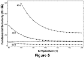
- Figure 5 shows exemplary fundamental sensitivity for L 2 of 100 (401), 200 (402) and 500 (403) microns, respectively.
- the present invention covers, but is not limited to, all sub-mm thickness conditions. Furthermore, atomic spin squeezing can improve the sensitivity below the standard quantum limit, and this is possible due to the high optical depth of the cavity microcell, not achievable with single pass miniaturized sensors (MEMS) as well as for the quantum-non-demolition nature of the dispersive measurement either in transmission or in reflection.
- MEMS single pass miniaturized sensors
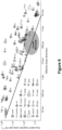
- Figure 6 shows the interesting region for applications of the cavity microcell for an atomic gradiometer.
- the design of the cavity cell of the first aspect of the present invention enables state-of-the-art sensitivity of optically-pumped atomic magnetic gradiometry with sub-mm spatial resolution, improving what is currently achievable with SQUIDs and cm scale or miniaturized OPMs in terms of trade-off between sensitivity, sensor size and spatial resolution.
- a pulse generator 107 drives the measurement sequence 110a. First, it triggers the pump laser 108 in a burst mode with high-power short pulses, synchronously with the Larmor precession frequency (Bell-Bloom operation mode), to generate maximum atomic polarization. Secondly, it triggers a CW (continuous Wave) probe beam 109 which propagates either in transmission ( Figure 7 ) or reflection ( Figure 8 ).
- CW continuous Wave
- Pump 108 and Probe 109 lasers are fibre coupled, by means of fibre coupler 110, and collimated in a collinear operation mode.
- the two lasers can propagate in free space and be aligned in the same mode through a dichroic mirror.
- pump and probe lights are meant to work at different frequencies, e.g. the pump light on resonance with the D1 line (e.g. 795 nm in Rb) and the probe far-detuned, ⁇ > 10 GHz, from the D2 line (e.g. 780 nm in Rb).
- Collinear pump and probe beams propagate along the z axis, transverse with respect to the magnetic field to be measured in the x direction 114/135 and to the long side of the cavity microcell 113.
- the cavity microcell is heated to increase the atomic density in the device to the desired value and the temperature is stabilized using a sensor-feedback system, e.g. a thermocouple and a PID circuit.
- the heater 112 is meant to be transparent, e.g. ITO or resistive heater. It can be deposited directly on the device, e.g. resistive heater, or attached to the microcell as a separated component, e.g. ITO thin film. Heating wires 112 can also heat a ceramic oven, e.g. boron nitride or Macor ® ceramics, surrounding the cavity cell 113 with free optical access windows and additional thermal insulating material to enclose the device, e.g. Teflon ® or PEEK (Polyether Ether Ketone). Heaters and possible oven components must be non-magnetic, i.e. the heating current always follow double path with opposite direction to cancel residual magnetic noise. Hot air of fiberized heaters and transparent absorptive plates can also be used to heat up 112 the cavity microcell 113.
- a ceramic oven e.g. boron nitride or Macor ® ceramics
- a linear polarizer 139 purifies the input polarization before a multi-order waveplate 111 linearly polarizes the probe light (e.g. 780 nm) and circularly polarize the pump beam (e.g. 795 nm).
- a beam splitter 131 and a reflective mirror 132 separate the single mode in two parallel beams, effectively giving two copies of the same optical system. This can be repeated providing multiple parallel beams for higher order gradiometer mode.
- the same pump and probe beam is scanned to impinge on different cavities at different times.
- the pulsed pump beam can last from few microseconds to milliseconds, depending on available power, impinges on the atomic ensemble in the microcell and its residual is absorbed by interference filters 115/133 that, on the other hand, transmit probe light.
- Top/Bottom probe beams propagate through the cavity microcell undergoing cavity-enhanced Faraday rotation, which is detected by conventional balanced polarimeters of a measuring unit.
- Each one consists of a half-waveplate 116/134, polarizing beam splitter 117/135 and two photodiodes 118-119/136-137.
- the signals are subtracted and amplified in each polarimeter by a differential transimpedance amplifier (TIA) 120/138, also included in the measuring unit.
- the outputs, the two gradiometer channels, are fed into a data acquisition card (DAQ) 121 or to frequency counters 122, also part of the measuring unit, where a final differential measurement is performed.
- DAQ data acquisition card
- the signal is processed with suitable software and electronics, also comprised by the measuring unit, to obtain Larmor frequency, magnetic field value and noise floor for each channel as well as magnetic field gradient with sub-mm spatial resolution and a baseline given by the distance between the two confining chambers that are probed.
- the noise is obtained in the frequency domain by repeating the same pump-probe measurement sequence 110a, driven by the pulse generator 107.
- One photodiode, e. g. 119 is used for continuously lock the probe laser frequency to the cavity length, via a PDH feedback circuit.
- the probe light is modulated 123, e.g.
- an electro optical modulator EOM
- EOM electro optical modulator
- a servo e.g. PID controller
- An additional servo system 129 can work as secondary feedback to a system 130, e.g. piezo-electric transducer or additional thin film heater, for fine cavity tuning.
- Figure 9A shows exemplary transmitted intensity and Figure 9B microcavity-enhanced Faraday rotation, for one gradiometer channel.
- the microcavity-enhanced Faraday rotation signal in transmission is shown in the graph of Figure 9B .
- the reflectance of the substrates can vary in different embodiments, to optimize the trade-off between high-finesse and residual probe beam absorption.
- the differential measurement between the two channels in a frequency counter provides the magnetic gradiometer signal.
- a polarizer 139 purifies the input linear polarization of both pump and probe beams.
- a beam splitter 131 and a reflective mirror 132 split the single mode in two beams.
- a polarizing beam splitter 140/144 and a quarter waveplate 141/145 circularly polarize both collinear pump and probe lasers. They can be collimated or focused by a lens 142/146, depending on the desired beam radius at atomic interaction.
- a lens can also be replaced by a system of lenses, i.e. a telescope, for fine beam shaping.
- the second glass substrate has a reflectance close to 1, e.g. 99,99%.
- the reflected probe light outputs are collected by photodiodes PDa/PDb 143/147 of a measuring unit and fed into a PDH laser frequency locking system to generate an error signal for each gradiometer channel.
- a probe modulator 123 e.g. an electro optical modulator (EOM)
- EOM electro optical modulator
- driving oscillator 124 e.g. an electro optical modulator
- mixer 126/149 that combines the photodiode 143/147 output with the main oscillator
- a low-pass filter 125/148 e.g. an electro optical modulator
- the error signals are fed to a servo 128, e.g. PID controller, of the measuring unit, that provides a feedback signal, e.g. a dc voltage output, to the probe laser current in order to keep the laser frequency on resonance, following the cavity microcell displacement ⁇ L .
- a servo 128, e.g. PID controller, of the measuring unit that provides a feedback signal, e.g. a dc voltage output, to the probe laser current in order to keep the laser frequency on resonance, following the cavity microcell displacement ⁇ L .
- a feedback signal e.g. a dc voltage output
- the signal processing performed by the measuring unit, can occur at different stages, by directly processing the reflected intensity or from the PDH error signals, where both show precession at the Larmor frequency and relaxation.
- the gradiometer measurement and the common mode noise rejection occur via a transimpedance differential amplifier 151 that subtracts the error signals from the two channels. Its output is then fed to DAQ 152 or frequency counter 153 to process the magnetic gradiometer signal.
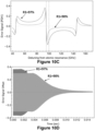
- FIGs 10A to 10D an exemplary reflected intensity and microcavity-enhanced PDH error signal for one gradiometer channel is reported.
- the probe laser frequency is initially locked to the cavity with unpolarized atoms.
- the optical pumping induces a shift of the cavity resonance condition with following free-induction-decay back to the unpolarized resonance condition.
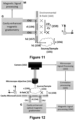
- FIG 11 shows an exemplary application of the cavity cell and gradiometer of the present invention, particularly for an embodiment for which the gradiometer is a total field optical magnetic gradiometer.
- Two gradiometer channels Ch1, Ch2 are included with baseline d 154, which refers to the distance between two parallel beams probing, in the illustrated embodiment, two physics cavities 101d with baseline 101L (see Figure 2B ), or, for a non-illustrated embodiment, two ensembles within the same physics cavity 101d with baseline smaller than 101j (see Figure 2B ).
- the optical and processing components of the gradiometer have been schematically depicted by means of blocks G and M.
- the gradiometer mode is obtained with a multi-element detector, e.g. a photodiode array, and d is set by the photodetector specs.
- the same beam is scanned to impinge on different cavities at different times.
- a sample 155 is the source of the magnetic field B x to be measured.
- the sample can have sub-mm dimensions s, 156, and be at sub-mm distance h2, 157, from the first channel Ch1 of the cavity microcell gradiometer.
- the sample 155 can also be a distant macroscopic object generating a magnetic field of appreciable magnitude at the sensor position.
- a magnetic gradient ⁇ B x / ⁇ B y , 159 can be measured by the cavity microcell with a baseline d.
- the magnetic gradient generated by the source adds to the magnetic environmental noise 160, e.g. Earth's field plus ambient noise sources, which is subtracted in the differential operation between the two gradiometer channels Ch1, Ch2.
- the distance h1 158 can be as small as the thickness of the top wall/substrate W1, e.g. 200 microns in the simulations performed by the present inventors.
- the all-optical cavity microcell gradiometer is small, compact, and light, can operate with high-sensitivity in shielded as well as in unshielded environments and it has sub-mm spatial resolution. Then, the cavity microcell can be used as total field magnetic gradiometer in miniaturized systems on moving platforms, like unmanned aerial and underwater vehicles (UAV, UUV), satellites, cars, planes, and drones. It can also be applied in biomedical applications that need sub-mm resolution, working with sub-mm sources of magnetic field, for instance for magneto-encephalography (MEG) of small animals.
- a total field gradiometer operation with sub-mm resolution can be applied to the detection of magnetic fields from magnetic nano-particles and in general from any sub-mm magnetic source.
- Figure 12 an embodiment of the system of the third aspect of the present invention is shown in Figure 12 , which comprises:
- system of the third aspect of the present invention constitutes an exemplary application of the cavity cell of the first aspect of the present invention as an optical magnetic gradiometer in combination with an imaging system, referred herein as optical magnetic microscopy.
- the microscopy system comprises a microscope objective 161 and a camera 162 that provide images and information about a sample 155 with sub-mm resolution.
- the sample 155 is placed on the top of the cavity cell 113 at stand-off distance h1 158, which can be as small as the thickness of the top wall/substrate W1, e.g. 200 microns in simulations performed by the present inventors.
- the magnetic information is obtained by the cavity-enhanced gradiometer optical setup G placed below the bottom wall/substrate W2, and including first and second channels Ch1, Ch2, since the measurement is performed in total reflection (see description above with reference to Figure 8 ) with a baseline d 154.
- the information from the microscope 163 and magnetic 164 signal processing can be combined in a correlation analysis processing 165, all such processing performed by a corresponding processing unit.
- the magnetic detection by the cavity microcell 113 is non-invasive and can performed in alternative or in combination with standard invasive techniques, used for example in electrophysiology and optogenetics, and more in general with any microscopic characterization.
- the sample could be:
Landscapes
- Physics & Mathematics (AREA)
- Condensed Matter Physics & Semiconductors (AREA)
- General Physics & Mathematics (AREA)
- Engineering & Computer Science (AREA)
- Power Engineering (AREA)
- Investigating Or Analysing Materials By Optical Means (AREA)
Priority Applications (3)
| Application Number | Priority Date | Filing Date | Title |
|---|---|---|---|
| EP21382888.2A EP4160239A1 (de) | 2021-10-01 | 2021-10-01 | Zelle für ein optisch gepumptes atommagnetgradiometer, ein optisch gepumptes atommagnetgradiometer und system mit dem gradiometer und mikroskopiesystem |
| US17/958,850 US12481008B2 (en) | 2021-10-01 | 2022-10-03 | Cavity cell for an optically-pumped atomic magnetometer and a magnetic gradiometer, and a system comprising the gradiometer and a microscopy system |
| US19/255,652 US20250327887A1 (en) | 2021-10-01 | 2025-06-30 | Cell for an optically-pumped atomic magnetic gradiometer, an optically-pumped atomic magnetic gradiometer, and a system comprising the gradiometer and a microscopy system |
Applications Claiming Priority (1)
| Application Number | Priority Date | Filing Date | Title |
|---|---|---|---|
| EP21382888.2A EP4160239A1 (de) | 2021-10-01 | 2021-10-01 | Zelle für ein optisch gepumptes atommagnetgradiometer, ein optisch gepumptes atommagnetgradiometer und system mit dem gradiometer und mikroskopiesystem |
Publications (1)
| Publication Number | Publication Date |
|---|---|
| EP4160239A1 true EP4160239A1 (de) | 2023-04-05 |
Family
ID=78413930
Family Applications (1)
| Application Number | Title | Priority Date | Filing Date |
|---|---|---|---|
| EP21382888.2A Pending EP4160239A1 (de) | 2021-10-01 | 2021-10-01 | Zelle für ein optisch gepumptes atommagnetgradiometer, ein optisch gepumptes atommagnetgradiometer und system mit dem gradiometer und mikroskopiesystem |
Country Status (2)
| Country | Link |
|---|---|
| US (1) | US12481008B2 (de) |
| EP (1) | EP4160239A1 (de) |
Families Citing this family (1)
| Publication number | Priority date | Publication date | Assignee | Title |
|---|---|---|---|---|
| US20250012875A1 (en) * | 2023-07-05 | 2025-01-09 | Deuve Photonics, Inc. | Stabilization of laser-based sensors |
Citations (5)
| Publication number | Priority date | Publication date | Assignee | Title |
|---|---|---|---|---|
| US20050206377A1 (en) * | 2002-10-16 | 2005-09-22 | The Trustees Of Princeton University | High sensitivity atomic magnetometer and methods for using same |
| US8212556B1 (en) * | 2010-01-12 | 2012-07-03 | Sandia Corporation | Atomic magnetometer |
| US20150377984A1 (en) * | 2011-02-16 | 2015-12-31 | Seiko Epson Corporation | Production method of gas cell, and gas cell |
| US20170356969A1 (en) * | 2016-06-14 | 2017-12-14 | Seiko Epson Corporation | Magnetic field measuring apparatus and manufacturing method of magnetic field measuring apparatus |
| US20170360322A1 (en) * | 2016-06-15 | 2017-12-21 | Seiko Epson Corporation | Magnetic field measuring apparatus and cell array |
Family Cites Families (2)
| Publication number | Priority date | Publication date | Assignee | Title |
|---|---|---|---|---|
| US9778329B2 (en) * | 2014-02-19 | 2017-10-03 | Infinitum Solutions, Inc. | Integrated optical nanoscale probe measurement of electric fields from electric charges in electronic devices |
| US11519989B2 (en) * | 2020-01-30 | 2022-12-06 | The Mitre Corporation | High-resolution magnetic field fingerprinting of integrated circuit activity with a quantum diamond microscope |
-
2021
- 2021-10-01 EP EP21382888.2A patent/EP4160239A1/de active Pending
-
2022
- 2022-10-03 US US17/958,850 patent/US12481008B2/en active Active
Patent Citations (5)
| Publication number | Priority date | Publication date | Assignee | Title |
|---|---|---|---|---|
| US20050206377A1 (en) * | 2002-10-16 | 2005-09-22 | The Trustees Of Princeton University | High sensitivity atomic magnetometer and methods for using same |
| US8212556B1 (en) * | 2010-01-12 | 2012-07-03 | Sandia Corporation | Atomic magnetometer |
| US20150377984A1 (en) * | 2011-02-16 | 2015-12-31 | Seiko Epson Corporation | Production method of gas cell, and gas cell |
| US20170356969A1 (en) * | 2016-06-14 | 2017-12-14 | Seiko Epson Corporation | Magnetic field measuring apparatus and manufacturing method of magnetic field measuring apparatus |
| US20170360322A1 (en) * | 2016-06-15 | 2017-12-21 | Seiko Epson Corporation | Magnetic field measuring apparatus and cell array |
Non-Patent Citations (2)
| Title |
|---|
| PERRY A R ET AL: "An all-optical atomic gradiometer with sub-20 fT/cm/sqrtrm Hz sensitivity in a 22 muT earth-scale magnetic field", ARXIV.ORG, CORNELL UNIVERSITY LIBRARY, 201 OLIN LIBRARY CORNELL UNIVERSITY ITHACA, NY 14853, 30 August 2020 (2020-08-30), XP081751625 * |
| PERRY ET AL.: "All-optical intrinsic atomic gradiometer with sub-20 fT/cm/VHz sensitivity in a 22 iT earth-scale magnetic field", OPTICS EXPRESS, vol. 28, 2020, pages 36696 - 36705 |
Also Published As
| Publication number | Publication date |
|---|---|
| US20230107226A1 (en) | 2023-04-06 |
| US12481008B2 (en) | 2025-11-25 |
Similar Documents
| Publication | Publication Date | Title |
|---|---|---|
| US11340320B2 (en) | Magnetometer for measuring an unknown external magnetic field | |
| Kumar et al. | Atom-based sensing of weak radio frequency electric fields using homodyne readout | |
| JP7470643B2 (ja) | 原子ベースの電磁場感知要素および測定システム | |
| Fan et al. | Atom based RF electric field sensing | |
| US9995800B1 (en) | Atomic magnetometer with multiple spatial channels | |
| US8446592B1 (en) | Scanning phase intracavity nanoscope | |
| US10620048B2 (en) | Apparatus and method for cavity-enhanced ultrafast two-dimensional spectroscopy | |
| Lucivero et al. | Laser-written vapor cells for chip-scale atomic sensing and spectroscopy | |
| Jiménez-Martínez et al. | Microfabricated optically-pumped magnetometers | |
| EP4231032B1 (de) | Atomare dampfzelle, integrierte atomare/photonische vorrichtung und gerät mit der atomaren dampfzelle und verfahren zur herstellung einer atomaren dampfzelle | |
| US11874311B1 (en) | Detecting radio frequency electromagnetic radiation using vapor cell sensors and comb spectra | |
| Salzenstein et al. | Investigation in acousto-optic laser stabilization for crystal resonator-based optoelectronic oscillators | |
| US12481008B2 (en) | Cavity cell for an optically-pumped atomic magnetometer and a magnetic gradiometer, and a system comprising the gradiometer and a microscopy system | |
| SUTER et al. | Laser excitation and detection of magnetic resonance | |
| Fartmann et al. | Ramsey-Bordé atom interferometry with a thermal strontium beam for a compact optical clock | |
| Zanoni et al. | Picotesla optically pumped magnetometer using a laser-written vapor cell with sub-mm cross section | |
| US20250327887A1 (en) | Cell for an optically-pumped atomic magnetic gradiometer, an optically-pumped atomic magnetic gradiometer, and a system comprising the gradiometer and a microscopy system | |
| Krelman et al. | Laser offset stabilization with chip-scale atomic diffractive elements | |
| Glick et al. | Doppler-free Rydberg spectroscopy in a warm vapor | |
| Lucivero et al. | Deliverable D4. 4 Micro-optical OPM physics package and encapsulation report | |
| Zanoni et al. | Laser-written micro-channel atomic magnetometer | |
| Rae | Alkali-atom absorption spectroscopy and magnetometry using functionalized MEMs vapor cells | |
| Fan | Microwave Electrometry with Rydberg Eletromagnetically Induced Transparency in Vapor Cells | |
| Karras | Cavity ring-down technique for optical coating characterization | |
| Cakli et al. | Power and Temperature Investigation for High-Resolution Atomic Spectroscopy |
Legal Events
| Date | Code | Title | Description |
|---|---|---|---|
| PUAI | Public reference made under article 153(3) epc to a published international application that has entered the european phase |
Free format text: ORIGINAL CODE: 0009012 |
|
| STAA | Information on the status of an ep patent application or granted ep patent |
Free format text: STATUS: THE APPLICATION HAS BEEN PUBLISHED |
|
| AK | Designated contracting states |
Kind code of ref document: A1 Designated state(s): AL AT BE BG CH CY CZ DE DK EE ES FI FR GB GR HR HU IE IS IT LI LT LU LV MC MK MT NL NO PL PT RO RS SE SI SK SM TR |
|
| STAA | Information on the status of an ep patent application or granted ep patent |
Free format text: STATUS: REQUEST FOR EXAMINATION WAS MADE |
|
| 17P | Request for examination filed |
Effective date: 20231004 |
|
| RBV | Designated contracting states (corrected) |
Designated state(s): AL AT BE BG CH CY CZ DE DK EE ES FI FR GB GR HR HU IE IS IT LI LT LU LV MC MK MT NL NO PL PT RO RS SE SI SK SM TR |