EP4160201A1 - System und verfahren zur bewertung der restlebensdauer von komponenten aus verbundwerkstoffen - Google Patents
System und verfahren zur bewertung der restlebensdauer von komponenten aus verbundwerkstoffen Download PDFInfo
- Publication number
- EP4160201A1 EP4160201A1 EP22196340.8A EP22196340A EP4160201A1 EP 4160201 A1 EP4160201 A1 EP 4160201A1 EP 22196340 A EP22196340 A EP 22196340A EP 4160201 A1 EP4160201 A1 EP 4160201A1
- Authority
- EP
- European Patent Office
- Prior art keywords
- defect
- ultrasound
- component
- location
- features
- Prior art date
- Legal status (The legal status is an assumption and is not a legal conclusion. Google has not performed a legal analysis and makes no representation as to the accuracy of the status listed.)
- Granted
Links
Images


Classifications
-
- G—PHYSICS
- G01—MEASURING; TESTING
- G01N—INVESTIGATING OR ANALYSING MATERIALS BY DETERMINING THEIR CHEMICAL OR PHYSICAL PROPERTIES
- G01N29/00—Investigating or analysing materials by the use of ultrasonic, sonic or infrasonic waves; Visualisation of the interior of objects by transmitting ultrasonic or sonic waves through the object
- G01N29/04—Analysing solids
- G01N29/06—Visualisation of the interior, e.g. acoustic microscopy
- G01N29/0654—Imaging
- G01N29/069—Defect imaging, localisation and sizing using, e.g. time of flight diffraction [TOFD], synthetic aperture focusing technique [SAFT], Amplituden-Laufzeit-Ortskurven [ALOK] technique
-
- G—PHYSICS
- G01—MEASURING; TESTING
- G01N—INVESTIGATING OR ANALYSING MATERIALS BY DETERMINING THEIR CHEMICAL OR PHYSICAL PROPERTIES
- G01N29/00—Investigating or analysing materials by the use of ultrasonic, sonic or infrasonic waves; Visualisation of the interior of objects by transmitting ultrasonic or sonic waves through the object
- G01N29/04—Analysing solids
- G01N29/043—Analysing solids in the interior, e.g. by shear waves
-
- G—PHYSICS
- G01—MEASURING; TESTING
- G01N—INVESTIGATING OR ANALYSING MATERIALS BY DETERMINING THEIR CHEMICAL OR PHYSICAL PROPERTIES
- G01N29/00—Investigating or analysing materials by the use of ultrasonic, sonic or infrasonic waves; Visualisation of the interior of objects by transmitting ultrasonic or sonic waves through the object
- G01N29/44—Processing the detected response signal, e.g. electronic circuits specially adapted therefor
- G01N29/4481—Neural networks
-
- G—PHYSICS
- G01—MEASURING; TESTING
- G01N—INVESTIGATING OR ANALYSING MATERIALS BY DETERMINING THEIR CHEMICAL OR PHYSICAL PROPERTIES
- G01N29/00—Investigating or analysing materials by the use of ultrasonic, sonic or infrasonic waves; Visualisation of the interior of objects by transmitting ultrasonic or sonic waves through the object
- G01N29/44—Processing the detected response signal, e.g. electronic circuits specially adapted therefor
- G01N29/46—Processing the detected response signal, e.g. electronic circuits specially adapted therefor by spectral analysis, e.g. Fourier analysis or wavelet analysis
-
- G—PHYSICS
- G01—MEASURING; TESTING
- G01N—INVESTIGATING OR ANALYSING MATERIALS BY DETERMINING THEIR CHEMICAL OR PHYSICAL PROPERTIES
- G01N2291/00—Indexing codes associated with group G01N29/00
- G01N2291/02—Indexing codes associated with the analysed material
- G01N2291/023—Solids
- G01N2291/0231—Composite or layered materials
-
- G—PHYSICS
- G01—MEASURING; TESTING
- G01N—INVESTIGATING OR ANALYSING MATERIALS BY DETERMINING THEIR CHEMICAL OR PHYSICAL PROPERTIES
- G01N2291/00—Indexing codes associated with group G01N29/00
- G01N2291/02—Indexing codes associated with the analysed material
- G01N2291/025—Change of phase or condition
- G01N2291/0258—Structural degradation, e.g. fatigue of composites, ageing of oils
-
- G—PHYSICS
- G01—MEASURING; TESTING
- G01N—INVESTIGATING OR ANALYSING MATERIALS BY DETERMINING THEIR CHEMICAL OR PHYSICAL PROPERTIES
- G01N2291/00—Indexing codes associated with group G01N29/00
- G01N2291/04—Wave modes and trajectories
- G01N2291/044—Internal reflections (echoes), e.g. on walls or defects
Definitions
- the disclosure herein generally relates to the field of structural health monitoring, and, more particularly, to a method and system for evaluating residual life of components made of composite materials.
- Composite materials are increasingly used in industries such as aerospace, transport, defense etc. for engineering structural applications. Any part or component made of composite materials can fail during its service life either due to manufacturing defects or due to damage caused by external loading or environment conditions. It essentially degrades the properties of composites materials thus affecting the residual life of the components.
- Structural health monitoring is a process to track the damages or defects during service life of structures comprising multiple components that accumulate damage gradually over a period of time and deteriorates the overall performance of the structures. It enables engineers to take critical decisions for repair or replacement of the components to avoid any further performance degradation and/or catastrophic failures.
- NDT Non-Destructive Testing
- NDTs also help in checking for defects, if any, after the manufacturing process. The comprehensive understanding of the defects or damages during manufacturing and in service enables designing the next generation components.
- a method for evaluating residual life of components made of composite materials includes transmitting a plurality of ultrasound signals towards a test component comprising a defect and receiving the plurality of ultrasound signals reflected by the test component. Further, a plurality of features comprising time-frequency and statistical features are extracted from each of the plurality of received ultrasound signals. Further, type of the defect in the test component is determined using a pre-trained classifier based on the plurality of features and a location of the defect comprised in the test component is determined based on time of flight analysis of the plurality of ultrasound signals.
- the location of the defect in the test component is scanned using a pulse echo ultrasound signal to determine depth of the defect comprised in the test component. Furthermore, the location of the defect in the test component is scanned by a thermal camera to estimate a dimension of the defect and residual life of the test component is predicted using a pre-trained machine learning model based on the type of the defect, the location of the defect, the depth of the defect and the dimension of the defect.
- a system for evaluating residual life of components made of composite materials includes a memory storing instructions; one or more communication interfaces; an ultrasound sensor; a pulse echo ultrasound sensor; a thermal camera and one or more hardware processors coupled to the memory via the one or more communication interfaces, wherein the one or more hardware processors are configured by the instructions to: transmit, via the ultrasound sensor, a plurality of ultrasound signals towards a test component comprising a defect and receiving the plurality of ultrasound signals reflected by the test component.
- the one or more hardware processors are configured to extract a plurality of features comprising time-frequency and statistical features from each of the plurality of received ultrasound signals and determine type of the defect in the test component using a pre-trained classifier based on the plurality of features.
- the one or more hardware processors are configured to determine a location of the defect comprised in the test component based on time of flight analysis of the plurality of ultrasound signals; scan, via the pulse echo ultrasound sensor, the location of the defect in the test component using a pulse echo ultrasound signal to determine depth of the defect; scan, via the thermal camera, the location of the defect in the test component to estimate a dimension of the defect; and predict residual life of the test component using a pre-trained machine learning model based on the type of the defect, the location of the defect, the depth of the defect and the dimension of the defect.
- one or more non-transitory machine-readable information storage mediums comprising one or more instructions which when executed by one or more hardware processors cause a method for material property prediction using element specific neural networks.
- the method includes transmitting a plurality of ultrasound signals towards a test component comprising a defect and receiving the plurality of ultrasound signals reflected by the test component. Further, a plurality of features comprising time-frequency and statistical features are extracted from the plurality of received ultrasound signals. Further, type of the defect in the test component is determined using a pre-trained classifier based on the plurality of features and a location of the defect comprised in the test component is determined based on time of flight analysis of the ultrasound signal.
- the location of the defect in the test component is scanned using a pulse echo ultrasound signal to determine depth of the defect comprised in the test component. Furthermore, the location of the defect in the test component is scanned by a thermal camera to estimate a dimension of the defect and residual life of the test component is predicted using a pre-trained machine learning model based on the type of the defect, the location of the defect, the depth of the defect and the dimension of the defect.
- the embodiments of the present disclosure provide a method and system for evaluating residual life of components made of composite materials.
- Existing methods require performing Non-Destructive Testing (NDT) on each of the components of a structure and further processing of results of NDT using computational methods such as Finite Element Analysis (FEA), Finite Element Method (FEM) etc.
- FEA Finite Element Analysis
- FEM Finite Element Method
- the computational methods are time consuming which increases overall time taken for determining residual life of the components.
- embodiments of present disclosure employ machine learning to reduce the time taken for analysis.
- initially a plurality of ultrasound signals are transmitted towards a test component comprising a defect and the plurality of ultrasound signals reflected by the test component is received.
- a plurality of features are extracted from the plurality of received ultrasound signals and type of the defect in the test component is determined using a pre-trained classifier based on the plurality of features. Further, a location of the defect comprised in the test component is determined based on time of flight analysis of the ultrasound signal and the location of the defect in the test component is scanned using a pulse echo ultrasound signal to determine depth of the defect comprised in the test component. Furthermore, the location of the defect in the test component is scanned by a thermal camera to estimate a dimension of the defect and residual life of the test component is predicted using a pre-trained machine learning model based on the type of the defect, the location of the defect, the depth of the defect and the dimension of the defect.
- the method eliminates the need of processing NDT and Finite Element Method (FEM) results repetitively during real time inspection of the component thereby making the decision faster, scalable, and efficient. Also, the method is fully automatic and reduces dependence on human experts. In addition, since the pre-trained classifier and ML model can be embedded in computer chips, the approach can lead to portable instruments for on-spot near real time estimation of residual life.
- FEM Finite Element Method
- FIG. 1 through 9 where similar reference characters denote corresponding features consistently throughout the figures, there are shown preferred embodiments and these embodiments are described in the context of the following exemplary system and/or method.
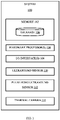
- FIG. 1 illustrates an exemplary system 100 for evaluating residual life of components made of composite materials, according to some embodiments of the present disclosure.
- the system 100 includes one or more processors 104, communication interface device(s) or Input/Output (I/O) interface(s) 106, one or more data storage devices or memory 102, an ultrasound sensor 110, a pulse echo ultrasound sensor 112, and a thermal camera 114 operatively coupled to the one or more processors 104.
- the memory 102 comprises a database 108.
- the one or more processors 104 that are hardware processors can be implemented as one or more microprocessors, microcomputers, microcontrollers, digital signal processors, central processing units, state machines, logic circuitries, and/or any devices that manipulate signals based on operational instructions.
- the processor(s) is configured to fetch and execute computer-readable instructions stored in the memory 102.
- the one or more processors 104 comprises a controller and an analysis unit.
- the controller actuates the ultrasound sensor 110, the pulse echo ultrasound sensor 112, the thermal camera 114 and a Data Acquisition unit (DAQ). Further it controls when Machine Learning (ML) driven analysis need to run and when the computed result need to be displayed on the I/O interface device(s) 106.
- DAQ is used to capture analog response of the ultrasound sensor, the pulse echo ultrasound sensor, and the thermal camera in digital form and store it in memory 102 so that it can be processed by the one or more hardware processors 104.
- the analysis unit implements the pre-trained classifier and the pre-trained machine learning model along with required data and signal processing using the hardware processors 104.
- the system 100 can be implemented in a variety of computing systems, such as laptop computers, notebooks, hand-held devices, workstations, mainframe computers, servers, a network cloud, and the like.
- the I/O interface device(s) 106 can include a variety of software and hardware interfaces, for example, a web interface, a graphical user interface, and the like and can facilitate multiple communications within a wide variety of networks N/W and protocol types, including wired networks, for example, LAN, cable, etc., and wireless networks, such as WLAN, cellular, or satellite.
- the I/O interface device(s) can include one or more ports for connecting a number of devices to one another or to another server.
- the I/O interface device(s) 106 display the defect parameters (for example, defect type, defect location and defect depth) and estimated residual life.
- the memory 102 may include any computer-readable medium known in the art including, for example, volatile memory, such as static random access memory (SRAM) and dynamic random access memory (DRAM), and/or non-volatile memory, such as read only memory (ROM), erasable programmable ROM, flash memories, hard disks, optical disks, and magnetic tapes.
- volatile memory such as static random access memory (SRAM) and dynamic random access memory (DRAM)
- non-volatile memory such as read only memory (ROM), erasable programmable ROM, flash memories, hard disks, optical disks, and magnetic tapes.
- the database 108 may store information but are not limited to, information associated with at least one of: (i) material parameters of the components, (ii) the pre-trained classifier, (iii) the pre-trained machine learning model, (iv) the defect parameters (defect location, defect type, defect depth, defect dimension) of the components and so on. Further, the database 108 stores information pertaining to inputs fed to the system
- the system 100 comprises one or more data storage devices or the memory 102 operatively coupled to the processor(s) 104 and is configured to store instructions for execution of steps of the method depicted in FIG. 2 by the processor(s) or one or more hardware processors 104.
- the steps of the method of the present disclosure will now be explained with reference to the components or blocks of the system 100 as depicted in FIG. 1 , the steps of flow diagrams as depicted in FIG. 2 , the block diagrams of FIGS. 3 , 4A and 4B and experimental results illustrated in FIGS. 5 to 9 .
- FIG. 2 is a flowchart illustrating method 200 for evaluating residual life of components made of composite materials, according to some embodiments of the present disclosure.
- a plurality of ultrasound signals are transmitted towards a test component, for example, sample, sheet, part, and the like, which comprises a defect such as damage, fault, flaw, scratch, crack, and the like, by the ultrasound sensor 110 controlled by the one or more hardware processors 104.
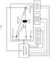
- the ultrasound sensor 110 comprises a transmitter (S T ) and one or more receivers (S 1 , S 2 ,...,S j ,...S N ) placed on the test component at locations S T (0,0), S 1 ( x 1 , y 1 ), S 2 ( x 2 , y 2 ),..., S j ( x j , y j ),..., S N ( x N , y N ) respectively as illustrated in FIG. 3 .
- each of the plurality of ultrasound signals is transmitted as a tone burst of 5 cycles with 150 kHz by the transmitter.
- the transmitter transmits each of the plurality of ultrasound signals with a frequency sweep (100 kHz to 1MHz) of 100 Hz frequency step size.
- the plurality of ultrasound signals are reflected or scattered by the test component which is received by the one or more receivers of the ultrasound sensor 110.
- the one or more hardware processors 104 are configured to extract a plurality of features comprising time-frequency and statistical features from the plurality of received ultrasound signals. From the reflected tone burst ultrasound signals, box-pierce statistic of Discrete Wavelet Transform (DWT), mean of windowed box-pierce statistic of DWT, Hjorth complexity time-domain and standard deviation of windowed box-pierce stat of DWT features are extracted.
- DWT Discrete Wavelet Transform
- mean of windowed box-pierce statistic of DWT mean of windowed box-pierce statistic of DWT
- Hjorth complexity time-domain and standard deviation of windowed box-pierce stat of DWT features are extracted.
- RMS Root Mean Square
- resonance spectrum is generated by plotting excitation frequency vs corresponding RMS values. From the plot, a plurality of features comprising resonance peak locations, amplitude of resonance peaks, width of resonance peaks and adjacent resonance peak to peak distance are extracted. Different time-frequency and statistical features maybe used in alternate embodiments.
- x ( n ) represents a reflected ultrasound signal among the plurality of reflected ultrasound signals for an ultrasound signal among the plurality of ultrasound signals transmitted as tone burst. It is passed through a low pass filter with impulse response g to perform DWT of the reflected ultrasound signal. Equation 1 gives output of the DWT p ( n ), wherein ⁇ is the convolution. Equation 2 gives the box-pierce statistic calculation, wherein ⁇ a , k 2 is the auto-correlation co-efficient at lag k of residual a t ⁇ , n is the number of terms in the x ( n ) and K is the maximum lag considered.
- ⁇ a , k 2 is given by equation 3 and hence the box-pierce statistic of DWT is calculated by equation 4.
- Equation 8 Standard deviation of windowed box-pierce statistic of DWT is calculated by equation 8, wherein w ( n ) is the windowed signal ( w signal ) determined by equation6 and BP ( k ) is determined by equation 4.
- Hjorth parameters are statistical properties used in signal processing in the time domain introduced by Bo Hjorth in 1970. The parameters are activity, mobility, and complexity.
- the Hjorth complexity parameter represents the change in frequency and is given by equation 8. It compares the signal's similarity to a pure sine wave, where the value converges to 1 if the signal is more similar.
- Complexity Mobility x n ⁇ x n ⁇ 1 Mobility x n , wherein x n is the ultrasound signal
- one or more hardware processors 104 are configured to determine type of the defect in the test component using a pre-trained classifier based on the plurality of features.
- the pre-trained classifier is ensemble adaptive boost classifier. Different classifiers maybe used in alternate embodiments.
- the pre-trained classifier is trained by first performing ultrasound test on a component without defect and a plurality of components with known defects, wherein the ultrasound test comprises transmitting a plurality of ultrasound signals to the component and recording the ultrasound signals reflected or scattered by the component. Then, the plurality of features are extracted from the results of the ultrasound test, and they are correlated with the known defects of the plurality of components. Finally, the classifier is trained using the plurality of features and corresponding defects.
- one or more hardware processors are configured to determine a location of the defect comprised in the test component based on time of flight analysis of each of the plurality of ultrasound signals.
- time of flight of the ultrasound signal is the time taken by the ultrasound signal to travel a certain distance through the test component. Calculations for one ultrasound signal among the plurality of ultrasound signals is explained herein. The location of the defect can be accurately determined by performing these calculations for the plurality of ultrasound signals in a similar way.
- V is the velocity of the ultrasound signal in the test component. The value of V can be calculated by using one transmitter and one receiver.
- ultrasonic tone burst signal (5 cycle tone burst with frequency 150 kHz) is applied on a component without any defects (undamaged component) by a transmitter (S T ) and the ultrasound signal reflected by the component is captured by a receiver placed at a known distance d.
- S T a transmitter
- d the ultrasound signal reflected by the component
- the transmitter is transmitting ultrasonic tone burst (5 cycle tone burst with 150KHz frequency).
- the ultrasound signal is reflected which is then detected at the plurality of receivers (S 1 , S 2 , ..., S N ).
- the ultrasound signal can travel in two ways to the receiver: (i) direct path from transmitter to receiver (shown as L S T -Sj in FIG. 3 ) and (ii) indirect path from transmitter to the defect ( L S T -D ) and from the defect to the receiver ( L D-S j ).
- equation 11 time difference of occurring between two consecutive received signals is computed by equation 11. It can be theoretically expressed as equation 12, wherein L S T -D is distance between transmitter of the ultrasound sensor and the defect and is calculated by equation 13, V is velocity of the ultrasound signal, L D-S j is distance between the defect and a receiver ( j ), among one or more receivers of the ultrasound sensor, calculated by equation 14, L S T -Sj is distance between the transmitter and the receiver ( j ) which is calculated by equation 15, and ⁇ t T-j is difference in time of flight of the ultrasound signal travelled via the direct path and the indirect path from the transmitter to the receiver.
- Equations 13, 14 and 15 are substituted in equation 12 to get equation 16 from which equation 17 is obtained by rearranging the terms.
- the equation 17 represents an ellipse indicating possible location of defect. It can be alternately written as equation 18. Similar equations for all the one or more receivers (say, N receivers) of the ultrasound sensor is derived. Now, ( x D , y D ) can be estimated by minimizing an objective function J as given by equation 19 to determine exact location of defect ( x D , y D ).
- one or more hardware processors 104 are configured to scan, via the pulse echo ultrasound sensor 112, the location of the defect in the test component using a pulse echo ultrasound signal to determine depth of the defect.
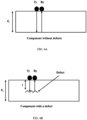
- the pulse echo ultrasound sensor 112 comprises a transmitter T y and a receiver R y and is placed near the test component as illustrated in FIGS. 3 , 4A and 4B .
- a pulse is sent by the transmitter and the reflected pulse is recorded by the receiver.
- the travel time of the pulse is calculated from the difference of pulse transmission time instant, and pulse received time instant.
- Speed of sound (v) in the component is known a prior. If there is no defect in the component then the pulse will travel the full depth ( d 1 ) as show in FIG. 4A .
- the travel time of the pulse ( T normal ) is calculated by equation 20. If there is a defect in the component (for example, the test component) then the pulse will be returned from the defect itself as shown in FIG. 4B . Suppose the defect is formed l units below the top surface (i.e. depth of defect formation is l ), then the travel time Tof the received pulse is given by equation 23. By measuring the travel time T and using known value of v, the equation 21 can be solved to determine the value of depth l as in equation 22.
- a predefined area ( ⁇ x d and ⁇ y d ) around the location of the defect ( x D , y D ) is scanned by the pulse-echo sensor.
- the number of scan points (n) can be predefined.
- each scan point (say i th point) provides a travel time (say T i ) corresponding to defect depth of l i . If ( T normal -T i ) > predefined threshold, then the depth l i is computed for that T i by equation 23.
- one or more hardware processors 104 is configured to scan, via the thermal camera 114, the location of the defect in the test component to estimate a dimension of the defect.
- the thermographic scan image is created which is centered at the location of defect ( x D , y D ).
- Image processing techniques are applied on the thermographic scan image to calculate the length and breadth of that image which in turn gives dimension of the defect. For example, a Lock-In thermography technique is used to determine the dimension of the defect.
- one or more hardware processors is configured to predict residual life of the test component using a pre-trained machine learning model based on the type of the defect, the location of the defect, the depth of the defect and the dimension of the defect.
- the pre-trained machine learning model is trained by first obtaining residual properties of a plurality of components with known defects, wherein the residual properties comprise stiffness, load bearing capacity etc.
- residual life of each of the plurality of components is determined using a material degradation mechanism and a computational method based on the defect in the component, one or more predefined loading conditions, and material properties of the component.
- the material degradation mechanism is fatigue and the computational method used is Finite Element Method (FEM).
- the machine learning model is trained using the residual life of the plurality of components, features of defects in the plurality of components for the one or more predefined loading conditions and the material properties of the plurality of components, wherein the features of defects comprise type of the defect, location of the defect, depth of the defect and dimension of the defect.
- the computational methods take a lot of time for execution and hence affects the calculation of residual life while assessing a test component.
- the time taken to assess a component will be reduced. This greatly improves the efficiency when large number of components are assessed on daily basis in industries such as aircraft or automobiles.
- the experiments are conducted using a test component (of size 460 mm x 305 mm x 2mm) and investigated for a crack as defect.
- the test component is made of G10/FR-4 composite material having short glass fibers ( ⁇ 10% volume fraction) in epoxy resin.
- FR-4 indicates Flame Retardant grade 4. This composite material is widely used as an insulator for electrical and electronic applications. It is also used for mechanical applications when outstanding strength, stiffness, and excellent creep resistance are required. Few properties of G10/FR4 material is listed in Table 1.
- the experimental setup is illustrated in FIG. 5 .
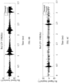
- An ultrasound signal having 5 cycle tone burst with 150kHz frequency is transmitted by the transmitter (Tx) which is reflected by the test component.
- the reflected signal is received by the receivers Rx1, Rx2 and Rx3 which is illustrated in FIGS. 6A , 6B and 6C respectively.
- the plurality of features are extracted from the reflected signals and fed into a trained adaptive boost classifier. It classifies the normal (component without defects or undamaged sample) and cracked sheet (test component) with 80% accuracy.
- the location and dimension of the defect is identified by visual inspection during the experiments. Then, residual life of the test component is predicted using the pre-trained machine learning model based on the type of the defect, the location of the defect, the depth of the defect and the dimension of the defect.
- the stress ratio is defined as the ratio of applied minimum stress to applied maximum stress.
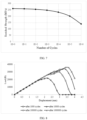
- v strength degradation parameter which is determined or derived from physical experiments. The results of applying fatigue degradation mechanism is illustrated in FIG. 7 .
- ⁇ N ⁇ ULT ⁇ ⁇ ULT ⁇ ⁇ max N N f v
- FEA is performed at a plurality of time steps by static structural analysis with element removal method, wherein any element with stress value going above residual strength is removed from the analysis in next timestep.
- the strength degradation is included in the FEA model. Instead of conducting analysis at each fatigue cycle, it is conducted at the interval of 1000 cycles. The fatigue loading is also replaced with maximum applied load.
- the element removal method is used to remove the elements having stress greater than instantaneous material strength. All these features save the simulation time with minimal loss of accuracy in prediction of load carrying capacity.
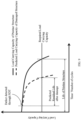
- the analysis is displacement controlled and load-displacement profile is extracted from analysis. The load carrying or bearing capacity and corresponding displacement is obtained from the load-displacement profile.
- Such computer-readable storage means contain program-code means for implementation of one or more steps of the method, when the program runs on a server or mobile device or any suitable programmable device.
- the hardware device can be any kind of device which can be programmed including e.g., any kind of computer like a server or a personal computer, or the like, or any combination thereof.
- the device may also include means which could be e.g., hardware means like e.g., an application-specific integrated circuit (ASIC), a field-programmable gate array (FPGA), or a combination of hardware and software means, e.g., an ASIC and an FPGA, or at least one microprocessor and at least one memory with software processing components located therein.
- the means can include both hardware means, and software means.
- the method embodiments described herein could be implemented in hardware and software.
- the device may also include software means. Alternatively, the embodiments may be implemented on different hardware devices, e.g., using a plurality of CPUs.
- the embodiments herein can comprise hardware and software elements.
- the embodiments that are implemented in software include but are not limited to, firmware, resident software, microcode, etc.
- the functions performed by various components described herein may be implemented in other components or combinations of other components.
- a computer-usable or computer readable medium can be any apparatus that can comprise, store, communicate, propagate, or transport the program for use by or in connection with the instruction execution system, apparatus, or device.
- a computer-readable storage medium refers to any type of physical memory on which information or data readable by a processor may be stored.
- a computer-readable storage medium may store instructions for execution by one or more processors, including instructions for causing the processor(s) to perform steps or stages consistent with the embodiments described herein.
- the term "computer-readable medium” should be understood to include tangible items and exclude carrier waves and transient signals, i.e., be non-transitory. Examples include random access memory (RAM), read-only memory (ROM), volatile memory, nonvolatile memory, hard drives, CD ROMs, DVDs, flash drives, disks, and any other known physical storage media.
Landscapes
- Physics & Mathematics (AREA)
- General Physics & Mathematics (AREA)
- Biochemistry (AREA)
- Life Sciences & Earth Sciences (AREA)
- Chemical & Material Sciences (AREA)
- Analytical Chemistry (AREA)
- General Health & Medical Sciences (AREA)
- Health & Medical Sciences (AREA)
- Immunology (AREA)
- Pathology (AREA)
- Engineering & Computer Science (AREA)
- Acoustics & Sound (AREA)
- Signal Processing (AREA)
- Mathematical Physics (AREA)
- Artificial Intelligence (AREA)
- Evolutionary Computation (AREA)
- Spectroscopy & Molecular Physics (AREA)
- Investigating Or Analyzing Materials By The Use Of Ultrasonic Waves (AREA)
- General Engineering & Computer Science (AREA)
- Theoretical Computer Science (AREA)
- Computational Linguistics (AREA)
- Data Mining & Analysis (AREA)
- Computing Systems (AREA)
- Software Systems (AREA)
Applications Claiming Priority (1)
| Application Number | Priority Date | Filing Date | Title |
|---|---|---|---|
| IN202121044015 | 2021-09-28 |
Publications (3)
| Publication Number | Publication Date |
|---|---|
| EP4160201A1 true EP4160201A1 (de) | 2023-04-05 |
| EP4160201B1 EP4160201B1 (de) | 2025-11-05 |
| EP4160201C0 EP4160201C0 (de) | 2025-11-05 |
Family
ID=83362382
Family Applications (1)
| Application Number | Title | Priority Date | Filing Date |
|---|---|---|---|
| EP22196340.8A Active EP4160201B1 (de) | 2021-09-28 | 2022-09-19 | System und verfahren zur bewertung der restlebensdauer von komponenten aus verbundwerkstoffen |
Country Status (2)
| Country | Link |
|---|---|
| US (1) | US12584887B2 (de) |
| EP (1) | EP4160201B1 (de) |
Cited By (1)
| Publication number | Priority date | Publication date | Assignee | Title |
|---|---|---|---|---|
| EP4530624A1 (de) * | 2023-09-29 | 2025-04-02 | Tata Consultancy Services Limited | Verfahren und system zur schadenslokalisierung unter verwendung einer niedrigenergiegeführten welle |
Families Citing this family (4)
| Publication number | Priority date | Publication date | Assignee | Title |
|---|---|---|---|---|
| JP2023152476A (ja) * | 2022-04-04 | 2023-10-17 | トヨタ自動車株式会社 | 検査装置、検査方法及び検査用コンピュータプログラム |
| CN119147640B (zh) * | 2024-11-15 | 2025-01-10 | 广东工业大学 | 一种基于奇异超小波的三维机织复合材料超声成像方法 |
| CN120217675B (zh) * | 2025-03-12 | 2026-03-24 | 北京航空航天大学 | 一种高温结构剩余寿命评估方法 |
| CN120294158B (zh) * | 2025-06-16 | 2025-09-12 | 中国海关科学技术研究中心 | 一种基于多模式激发源的金属材料检测方法及装置 |
Citations (1)
| Publication number | Priority date | Publication date | Assignee | Title |
|---|---|---|---|---|
| WO2021068848A1 (zh) * | 2019-10-09 | 2021-04-15 | 山东大学 | 隧道结构病害多尺度检测与智能诊断系统及方法 |
Family Cites Families (4)
| Publication number | Priority date | Publication date | Assignee | Title |
|---|---|---|---|---|
| US10473603B2 (en) | 2017-04-18 | 2019-11-12 | Saudi Arabian Oil Company | Apparatus, system and method for inspecting composite structures using quantitative infra-red thermography |
| US20220019190A1 (en) | 2020-07-14 | 2022-01-20 | Saudi Arabian Oil Company | Machine learning-based methods and systems for deffect detection and analysis using ultrasound scans |
| US20220018811A1 (en) * | 2020-07-14 | 2022-01-20 | Saudi Arabian Oil Company | Machine learning method for the denoising of ultrasound scans of composite slabs and pipes |
| CN113204923B (zh) | 2021-05-19 | 2023-04-07 | 广州大学 | 复合材料冲击后剩余强度预测方法、系统、装置及介质 |
-
2022
- 2022-09-19 EP EP22196340.8A patent/EP4160201B1/de active Active
- 2022-09-21 US US17/934,187 patent/US12584887B2/en active Active
Patent Citations (1)
| Publication number | Priority date | Publication date | Assignee | Title |
|---|---|---|---|---|
| WO2021068848A1 (zh) * | 2019-10-09 | 2021-04-15 | 山东大学 | 隧道结构病害多尺度检测与智能诊断系统及方法 |
Non-Patent Citations (1)
| Title |
|---|
| SHRIFAN NAWAF H M M ET AL: "Prospect of Using Artificial Intelligence for Microwave Nondestructive Testing Technique: A Review", IEEE ACCESS, vol. 7, 9 August 2019 (2019-08-09), pages 110628 - 110650, XP011741629, [retrieved on 20190819], DOI: 10.1109/ACCESS.2019.2934143 * |
Cited By (1)
| Publication number | Priority date | Publication date | Assignee | Title |
|---|---|---|---|---|
| EP4530624A1 (de) * | 2023-09-29 | 2025-04-02 | Tata Consultancy Services Limited | Verfahren und system zur schadenslokalisierung unter verwendung einer niedrigenergiegeführten welle |
Also Published As
| Publication number | Publication date |
|---|---|
| EP4160201B1 (de) | 2025-11-05 |
| US20230095525A1 (en) | 2023-03-30 |
| US12584887B2 (en) | 2026-03-24 |
| EP4160201C0 (de) | 2025-11-05 |
Similar Documents
| Publication | Publication Date | Title |
|---|---|---|
| EP4160201A1 (de) | System und verfahren zur bewertung der restlebensdauer von komponenten aus verbundwerkstoffen | |
| Cawley | Structural health monitoring: Closing the gap between research and industrial deployment | |
| US7333898B2 (en) | Passive structural assessment and monitoring system and associated method | |
| de la Hermosa Gonzalez et al. | Pattern recognition by wavelet transforms using macro fibre composites transducers | |
| Yanez-Borjas et al. | Statistical time features for global corrosion assessment in a truss bridge from vibration signals | |
| Bandara et al. | Damage detection of in service timber poles using Hilbert-Huang transform | |
| Luo et al. | Structural health monitoring of carbon fiber reinforced polymer composite laminates for offshore wind turbine blades based on dual maximum correlation coefficient method | |
| CN118656586A (zh) | 强震下变电站结构易损性分析与韧性评估方法及系统 | |
| CN119598611A (zh) | 用于微型无人机的航空发动机叶片无损探伤检测方法 | |
| Shinagam et al. | Development of a machine learning algorithm for efficient localization of damage in a composite structure using random forest technique | |
| CN110568083A (zh) | 一种针对钢材腐蚀疲劳损伤在线监测的声发射检测方法 | |
| CN115063337A (zh) | 埋地管道智能维修决策方法及装置 | |
| Dadashbaki et al. | Autonomous structural health monitoring of composite wind turbine blades using guided waves and machine learning | |
| Aldrin et al. | Model‐assisted probabilistic reliability assessment for structural health monitoring systems | |
| Szeleziński et al. | Analysis of ability to detect defects in welding structures with usage of dynamic characteristics spectrums | |
| Boubaker et al. | Inspection of baked carbon anodes using a combination of multi-spectral acousto-ultrasonic techniques and principal component analysis | |
| Scherr et al. | Evaluation of non-destructive impact-echo data from the national bridge inventory | |
| US20060106551A1 (en) | Method for reducing the computation resources required for determining damage in structural health management system | |
| Katam et al. | SVM-assisted damage identification in cantilever steel beam using vibration-based method | |
| Keßler et al. | „Reliability Assessment of NDT in Civil Engineering–the German Approach for Standardization (normPOD)” | |
| Karbhari et al. | Operational modal analysis for vibration-based structural health monitoring of civil structures | |
| Habbal et al. | Cracks detection using artificial intelligence to enhance inspection efficiency and analyze the critical defects | |
| Malik et al. | An Information Theory Approach for Internet of Things Enabled Damage Monitoring | |
| CN118521530B (zh) | 基于图像处理的太赫兹安全检测方法及系统 | |
| EP4530624B1 (de) | Verfahren und system zur schadenslokalisierung unter verwendung einer niedrigenergiegeführten welle |
Legal Events
| Date | Code | Title | Description |
|---|---|---|---|
| PUAI | Public reference made under article 153(3) epc to a published international application that has entered the european phase |
Free format text: ORIGINAL CODE: 0009012 |
|
| STAA | Information on the status of an ep patent application or granted ep patent |
Free format text: STATUS: THE APPLICATION HAS BEEN PUBLISHED |
|
| AK | Designated contracting states |
Kind code of ref document: A1 Designated state(s): AL AT BE BG CH CY CZ DE DK EE ES FI FR GB GR HR HU IE IS IT LI LT LU LV MC MK MT NL NO PL PT RO RS SE SI SK SM TR |
|
| STAA | Information on the status of an ep patent application or granted ep patent |
Free format text: STATUS: REQUEST FOR EXAMINATION WAS MADE |
|
| 17P | Request for examination filed |
Effective date: 20230707 |
|
| RBV | Designated contracting states (corrected) |
Designated state(s): AL AT BE BG CH CY CZ DE DK EE ES FI FR GB GR HR HU IE IS IT LI LT LU LV MC MK MT NL NO PL PT RO RS SE SI SK SM TR |
|
| STAA | Information on the status of an ep patent application or granted ep patent |
Free format text: STATUS: EXAMINATION IS IN PROGRESS |
|
| 17Q | First examination report despatched |
Effective date: 20250107 |
|
| GRAP | Despatch of communication of intention to grant a patent |
Free format text: ORIGINAL CODE: EPIDOSNIGR1 |
|
| STAA | Information on the status of an ep patent application or granted ep patent |
Free format text: STATUS: GRANT OF PATENT IS INTENDED |
|
| INTG | Intention to grant announced |
Effective date: 20250618 |
|
| GRAS | Grant fee paid |
Free format text: ORIGINAL CODE: EPIDOSNIGR3 |
|
| GRAA | (expected) grant |
Free format text: ORIGINAL CODE: 0009210 |
|
| STAA | Information on the status of an ep patent application or granted ep patent |
Free format text: STATUS: THE PATENT HAS BEEN GRANTED |
|
| AK | Designated contracting states |
Kind code of ref document: B1 Designated state(s): AL AT BE BG CH CY CZ DE DK EE ES FI FR GB GR HR HU IE IS IT LI LT LU LV MC MK MT NL NO PL PT RO RS SE SI SK SM TR |
|
| REG | Reference to a national code |
Ref country code: CH Ref legal event code: F10 Free format text: ST27 STATUS EVENT CODE: U-0-0-F10-F00 (AS PROVIDED BY THE NATIONAL OFFICE) Effective date: 20251105 Ref country code: GB Ref legal event code: FG4D Ref country code: CH Ref legal event code: R17 Free format text: ST27 STATUS EVENT CODE: U-0-0-R10-R17 (AS PROVIDED BY THE NATIONAL OFFICE) Effective date: 20251105 |
|
| REG | Reference to a national code |
Ref country code: IE Ref legal event code: FG4D |
|
| U01 | Request for unitary effect filed |
Effective date: 20251105 |
|
| U07 | Unitary effect registered |
Designated state(s): AT BE BG DE DK EE FI FR IT LT LU LV MT NL PT RO SE SI Effective date: 20251111 |
|
| PG25 | Lapsed in a contracting state [announced via postgrant information from national office to epo] |
Ref country code: ES Free format text: LAPSE BECAUSE OF FAILURE TO SUBMIT A TRANSLATION OF THE DESCRIPTION OR TO PAY THE FEE WITHIN THE PRESCRIBED TIME-LIMIT Effective date: 20251105 |
|
| PG25 | Lapsed in a contracting state [announced via postgrant information from national office to epo] |
Ref country code: NO Free format text: LAPSE BECAUSE OF FAILURE TO SUBMIT A TRANSLATION OF THE DESCRIPTION OR TO PAY THE FEE WITHIN THE PRESCRIBED TIME-LIMIT Effective date: 20260205 |
|
| PG25 | Lapsed in a contracting state [announced via postgrant information from national office to epo] |
Ref country code: HR Free format text: LAPSE BECAUSE OF FAILURE TO SUBMIT A TRANSLATION OF THE DESCRIPTION OR TO PAY THE FEE WITHIN THE PRESCRIBED TIME-LIMIT Effective date: 20251105 |
|
| PG25 | Lapsed in a contracting state [announced via postgrant information from national office to epo] |
Ref country code: RS Free format text: LAPSE BECAUSE OF FAILURE TO SUBMIT A TRANSLATION OF THE DESCRIPTION OR TO PAY THE FEE WITHIN THE PRESCRIBED TIME-LIMIT Effective date: 20260205 |
|
| PG25 | Lapsed in a contracting state [announced via postgrant information from national office to epo] |
Ref country code: IS Free format text: LAPSE BECAUSE OF FAILURE TO SUBMIT A TRANSLATION OF THE DESCRIPTION OR TO PAY THE FEE WITHIN THE PRESCRIBED TIME-LIMIT Effective date: 20260305 |