EP4160110A1 - Refrigeration cycle device - Google Patents
Refrigeration cycle device Download PDFInfo
- Publication number
- EP4160110A1 EP4160110A1 EP20939438.6A EP20939438A EP4160110A1 EP 4160110 A1 EP4160110 A1 EP 4160110A1 EP 20939438 A EP20939438 A EP 20939438A EP 4160110 A1 EP4160110 A1 EP 4160110A1
- Authority
- EP
- European Patent Office
- Prior art keywords
- refrigerant
- compressor
- refrigeration cycle
- cycle apparatus
- heat
- Prior art date
- Legal status (The legal status is an assumption and is not a legal conclusion. Google has not performed a legal analysis and makes no representation as to the accuracy of the status listed.)
- Withdrawn
Links
Images

Classifications
-
- F—MECHANICAL ENGINEERING; LIGHTING; HEATING; WEAPONS; BLASTING
- F25—REFRIGERATION OR COOLING; COMBINED HEATING AND REFRIGERATION SYSTEMS; HEAT PUMP SYSTEMS; MANUFACTURE OR STORAGE OF ICE; LIQUEFACTION SOLIDIFICATION OF GASES
- F25B—REFRIGERATION MACHINES, PLANTS OR SYSTEMS; COMBINED HEATING AND REFRIGERATION SYSTEMS; HEAT PUMP SYSTEMS
- F25B13/00—Compression machines, plants or systems, with reversible cycle
-
- F—MECHANICAL ENGINEERING; LIGHTING; HEATING; WEAPONS; BLASTING
- F25—REFRIGERATION OR COOLING; COMBINED HEATING AND REFRIGERATION SYSTEMS; HEAT PUMP SYSTEMS; MANUFACTURE OR STORAGE OF ICE; LIQUEFACTION SOLIDIFICATION OF GASES
- F25B—REFRIGERATION MACHINES, PLANTS OR SYSTEMS; COMBINED HEATING AND REFRIGERATION SYSTEMS; HEAT PUMP SYSTEMS
- F25B49/00—Arrangement or mounting of control or safety devices
- F25B49/02—Arrangement or mounting of control or safety devices for compression type machines, plants or systems
-
- F—MECHANICAL ENGINEERING; LIGHTING; HEATING; WEAPONS; BLASTING
- F25—REFRIGERATION OR COOLING; COMBINED HEATING AND REFRIGERATION SYSTEMS; HEAT PUMP SYSTEMS; MANUFACTURE OR STORAGE OF ICE; LIQUEFACTION SOLIDIFICATION OF GASES
- F25B—REFRIGERATION MACHINES, PLANTS OR SYSTEMS; COMBINED HEATING AND REFRIGERATION SYSTEMS; HEAT PUMP SYSTEMS
- F25B29/00—Combined heating and refrigeration systems, e.g. operating alternately or simultaneously
- F25B29/003—Combined heating and refrigeration systems, e.g. operating alternately or simultaneously of the compression type system
-
- F—MECHANICAL ENGINEERING; LIGHTING; HEATING; WEAPONS; BLASTING
- F25—REFRIGERATION OR COOLING; COMBINED HEATING AND REFRIGERATION SYSTEMS; HEAT PUMP SYSTEMS; MANUFACTURE OR STORAGE OF ICE; LIQUEFACTION SOLIDIFICATION OF GASES
- F25B—REFRIGERATION MACHINES, PLANTS OR SYSTEMS; COMBINED HEATING AND REFRIGERATION SYSTEMS; HEAT PUMP SYSTEMS
- F25B41/00—Fluid-circulation arrangements
- F25B41/20—Disposition of valves, e.g. of on-off valves or flow control valves
-
- F—MECHANICAL ENGINEERING; LIGHTING; HEATING; WEAPONS; BLASTING
- F25—REFRIGERATION OR COOLING; COMBINED HEATING AND REFRIGERATION SYSTEMS; HEAT PUMP SYSTEMS; MANUFACTURE OR STORAGE OF ICE; LIQUEFACTION SOLIDIFICATION OF GASES
- F25B—REFRIGERATION MACHINES, PLANTS OR SYSTEMS; COMBINED HEATING AND REFRIGERATION SYSTEMS; HEAT PUMP SYSTEMS
- F25B41/00—Fluid-circulation arrangements
- F25B41/20—Disposition of valves, e.g. of on-off valves or flow control valves
- F25B41/22—Disposition of valves, e.g. of on-off valves or flow control valves between evaporator and compressor
-
- F—MECHANICAL ENGINEERING; LIGHTING; HEATING; WEAPONS; BLASTING
- F25—REFRIGERATION OR COOLING; COMBINED HEATING AND REFRIGERATION SYSTEMS; HEAT PUMP SYSTEMS; MANUFACTURE OR STORAGE OF ICE; LIQUEFACTION SOLIDIFICATION OF GASES
- F25B—REFRIGERATION MACHINES, PLANTS OR SYSTEMS; COMBINED HEATING AND REFRIGERATION SYSTEMS; HEAT PUMP SYSTEMS
- F25B41/00—Fluid-circulation arrangements
- F25B41/30—Expansion means; Dispositions thereof
- F25B41/39—Dispositions with two or more expansion means arranged in series, i.e. multi-stage expansion, on a refrigerant line leading to the same evaporator
-
- F—MECHANICAL ENGINEERING; LIGHTING; HEATING; WEAPONS; BLASTING
- F25—REFRIGERATION OR COOLING; COMBINED HEATING AND REFRIGERATION SYSTEMS; HEAT PUMP SYSTEMS; MANUFACTURE OR STORAGE OF ICE; LIQUEFACTION SOLIDIFICATION OF GASES
- F25B—REFRIGERATION MACHINES, PLANTS OR SYSTEMS; COMBINED HEATING AND REFRIGERATION SYSTEMS; HEAT PUMP SYSTEMS
- F25B5/00—Compression machines, plants or systems, with several evaporator circuits, e.g. for varying refrigerating capacity
- F25B5/04—Compression machines, plants or systems, with several evaporator circuits, e.g. for varying refrigerating capacity arranged in series
-
- F—MECHANICAL ENGINEERING; LIGHTING; HEATING; WEAPONS; BLASTING
- F25—REFRIGERATION OR COOLING; COMBINED HEATING AND REFRIGERATION SYSTEMS; HEAT PUMP SYSTEMS; MANUFACTURE OR STORAGE OF ICE; LIQUEFACTION SOLIDIFICATION OF GASES
- F25B—REFRIGERATION MACHINES, PLANTS OR SYSTEMS; COMBINED HEATING AND REFRIGERATION SYSTEMS; HEAT PUMP SYSTEMS
- F25B9/00—Compression machines, plants or systems, in which the refrigerant is air or other gas of low boiling point
- F25B9/002—Compression machines, plants or systems, in which the refrigerant is air or other gas of low boiling point characterised by the refrigerant
-
- F—MECHANICAL ENGINEERING; LIGHTING; HEATING; WEAPONS; BLASTING
- F25—REFRIGERATION OR COOLING; COMBINED HEATING AND REFRIGERATION SYSTEMS; HEAT PUMP SYSTEMS; MANUFACTURE OR STORAGE OF ICE; LIQUEFACTION SOLIDIFICATION OF GASES
- F25B—REFRIGERATION MACHINES, PLANTS OR SYSTEMS; COMBINED HEATING AND REFRIGERATION SYSTEMS; HEAT PUMP SYSTEMS
- F25B2400/00—Component parts or details not otherwise provided for in this subclass
- F25B2400/04—Refrigeration circuit bypassing means
- F25B2400/0419—Refrigeration circuit bypassing means for superheaters
-
- F—MECHANICAL ENGINEERING; LIGHTING; HEATING; WEAPONS; BLASTING
- F25—REFRIGERATION OR COOLING; COMBINED HEATING AND REFRIGERATION SYSTEMS; HEAT PUMP SYSTEMS; MANUFACTURE OR STORAGE OF ICE; LIQUEFACTION SOLIDIFICATION OF GASES
- F25B—REFRIGERATION MACHINES, PLANTS OR SYSTEMS; COMBINED HEATING AND REFRIGERATION SYSTEMS; HEAT PUMP SYSTEMS
- F25B2400/00—Component parts or details not otherwise provided for in this subclass
- F25B2400/05—Compression system with heat exchange between particular parts of the system
- F25B2400/054—Compression system with heat exchange between particular parts of the system between the suction tube of the compressor and another part of the cycle
-
- F—MECHANICAL ENGINEERING; LIGHTING; HEATING; WEAPONS; BLASTING
- F25—REFRIGERATION OR COOLING; COMBINED HEATING AND REFRIGERATION SYSTEMS; HEAT PUMP SYSTEMS; MANUFACTURE OR STORAGE OF ICE; LIQUEFACTION SOLIDIFICATION OF GASES
- F25B—REFRIGERATION MACHINES, PLANTS OR SYSTEMS; COMBINED HEATING AND REFRIGERATION SYSTEMS; HEAT PUMP SYSTEMS
- F25B2600/00—Control issues
- F25B2600/25—Control of valves
- F25B2600/2501—Bypass valves
-
- F—MECHANICAL ENGINEERING; LIGHTING; HEATING; WEAPONS; BLASTING
- F25—REFRIGERATION OR COOLING; COMBINED HEATING AND REFRIGERATION SYSTEMS; HEAT PUMP SYSTEMS; MANUFACTURE OR STORAGE OF ICE; LIQUEFACTION SOLIDIFICATION OF GASES
- F25B—REFRIGERATION MACHINES, PLANTS OR SYSTEMS; COMBINED HEATING AND REFRIGERATION SYSTEMS; HEAT PUMP SYSTEMS
- F25B2600/00—Control issues
- F25B2600/25—Control of valves
- F25B2600/2515—Flow valves
Definitions
- the present disclosure relates to a refrigeration cycle apparatus.
- a coefficient of performance For a refrigeration cycle apparatus, a coefficient of performance (COP) is used as an index representing the performance of the refrigeration cycle apparatus.
- the COP having a larger value means that a larger refrigeration capacity is achieved with smaller consumed compression power.
- a method of improving the value of the COP for a refrigeration cycle apparatus a method of increasing the degree of superheat (the degree of suction superheat) of the refrigerant suctioned into a compressor has been known.
- R290 propane
- PTL 1 discloses a refrigeration cycle apparatus using R290 as refrigerant.
- the value of the COP is increased by increasing the degree of suction superheat.
- the degree of suction superheat is increased too high, the value of the COP tends to become smaller, with the result that the performance of the refrigeration cycle apparatus degrades.
- the present disclosure has been made in order to solve the above-described problems, and an object of the present disclosure is to provide a refrigeration cycle apparatus that can be maximized in performance by adjusting the degree of suction superheat.
- One refrigeration cycle apparatus is a refrigeration cycle apparatus using R290 as refrigerant, and includes a compressor, a condenser, an expansion valve, an evaporator, a refrigerant pipe, a heat absorber, a heat source, a branch pipe, and a flow rate regulating valve.
- the refrigerant pipe is connected to the compressor, the condenser, the expansion valve, the evaporator, and the compressor in sequential order, and the refrigerant flows through the refrigerant pipe.
- the heat absorber is provided in a portion of the refrigerant pipe, and the portion connects the evaporator and the compressor.
- the heat source is disposed in contact with the heat absorber and is higher in temperature than the refrigerant having flowed through the evaporator.
- the branch pipe is connected in parallel with the portion provided with the heat absorber in the refrigerant pipe.
- the flow rate regulating valve is provided in the branch pipe and configured to regulate a flow rate of the refrigerant.
- Another refrigeration cycle apparatus is a refrigeration cycle apparatus including a compressor, a condenser, an expansion valve, and an evaporator, and includes a refrigerant pipe, a heat absorber, a heat source, and a branch pipe.
- the refrigerant pipe is connected to the compressor, the condenser, the expansion valve, the evaporator, and the compressor in sequential order, and refrigerant flows through the refrigerant pipe.
- the heat absorber is provided in a portion of the refrigerant pipe, and the portion connects the evaporator and the compressor.
- the heat source is disposed in contact with the heat absorber.
- the branch pipe is connected in parallel with the portion provided with the heat absorber in the refrigerant pipe.
- the refrigerant has a property that, as a degree of superheat of the refrigerant having flowed through the heat absorber increases, a coefficient of performance increases and subsequently decreases.
- the branch pipe is provided with a flow rate regulating valve configured to regulate a flow rate of the refrigerant.
- a heat absorber is provided in the portion between the evaporator and the compressor in the refrigerant pipe.
- the heat absorber is disposed in contact with the heat source.
- a branch pipe is connected in parallel with the portion provided with the heat absorber in the refrigerant pipe.
- the branch pipe is provided with a flow rate regulating valve configured to regulate a flow rate of the refrigerant.
- a heat absorber is provided in a portion between the evaporator and the compressor in the refrigerant pipe.
- the heat absorber is disposed in contact with the heat source.
- a branch pipe is connected in parallel with the portion provided with the heat absorber in the refrigerant pipe.
- the branch pipe is provided with a flow rate regulating valve configured to regulate a flow rate of the refrigerant.
- the refrigerant has a property that, as the degree of superheat of the refrigerant having flowed through the heat absorber increases, the coefficient of performance increases and subsequently decreases.
- the flow rate of the refrigerant flowing through the heat absorber can be regulated by the flow rate regulating valve, and thus, the degree of suction superheat of the refrigerant suctioned into the compressor can be adjusted. As a result, the value of the COP of the refrigeration cycle apparatus can be improved.
- FIG. 1 shows an example of a refrigerant circuit of a refrigeration cycle apparatus 1.
- refrigeration cycle apparatus 1 includes a compressor 3, a four-way valve 15, a first heat exchanger 5, an expansion valve 9, and a second heat exchanger 11.
- Refrigeration cycle apparatus 1 further includes a flow rate regulating valve 21, a heat absorber 17, and a heat source 19.
- a first blower 7 is disposed in first heat exchanger 5.
- a second blower 13 is disposed in second heat exchanger 11.
- an electric component 19a is disposed that accommodates a control circuit and the like for controlling the operation of refrigeration cycle apparatus 1.
- Compressor 3 four-way valve 15, first heat exchanger 5 (a condenser/an evaporator), expansion valve 9, second heat exchanger 11 (an evaporator /a condenser), and compressor 3 are connected sequentially in this order by a refrigerant pipe 31 through which refrigerant flows.
- R290 propane is used as refrigerant flowing through refrigerant pipe 31 and the like.
- Heat absorber 17 is provided in a portion of refrigerant pipe 31 between the evaporator (first heat exchanger 5 or second heat exchanger 11) and compressor 3. Heat absorber 17 is disposed in contact with electric component 19a serving as a heat source. More specifically, heat absorber 17 is provided in a portion of refrigerant pipe 31 that connects four-way valve 15 and compressor 3. A branch pipe 33 is connected in parallel with the portion provided with heat absorber 17 in refrigerant pipe 31. Branch pipe 33 is provided with a flow rate regulating valve 21 configured to regulate the flow rate of the refrigerant. Refrigeration cycle apparatus 1 according to the present embodiment is configured as described above.
- compressor 3 four-way valve 15, second heat exchanger 11, expansion valve 9, first heat exchanger 5, four-way valve 15, heat absorber 17, and compressor 3 are connected sequentially in this order by refrigerant pipe 31.
- compressor 3 high-temperature and high-pressure gas refrigerant is discharged from compressor 3.
- the discharged high-temperature and high-pressure gas refrigerant flows into second heat exchanger 11 through four-way valve 15.
- second heat exchanger 11 functions as a condenser.
- second heat exchanger 11 functioning as a condenser, heat exchange is performed between the incoming gas refrigerant and the air supplied by second blower 13.
- the high-temperature and high-pressure gas refrigerant is condensed into high-pressure liquid refrigerant (of a single phase).
- high-pressure liquid refrigerant for example, a room is heated.
- the high-pressure liquid refrigerant delivered from second heat exchanger 11 is converted by expansion valve 9 into low-pressure gas-liquid two-phase refrigerant.
- the two-phase refrigerant flows into first heat exchanger 5.
- first heat exchanger 5 functions as an evaporator.
- first heat exchanger 5 functioning as an evaporator, heat exchange is performed between the incoming two-phase refrigerant and the air supplied by first blower 7. Then, liquid refrigerant is evaporated from the two-phase refrigerant, which results in low-pressure gas refrigerant (of a single phase).
- the low-pressure gas refrigerant delivered from first heat exchanger 5 passes through four-way valve 15 and flows into compressor 3 through heat absorber 17 or flow rate regulating valve 21.
- the low-pressure gas refrigerant flowing into compressor 3 is compressed into high-temperature and high-pressure gas refrigerant, and then discharged from compressor 3 again. This cycle is thereafter repeated.
- the functions of flow rate regulating valve 21 and heat absorber 17 will be described later.
- compressor 3, four-way valve 15, first heat exchanger 5, expansion valve 9, second heat exchanger 11, four-way valve 15, heat absorber 17, and compressor 3 are connected sequentially in this order by refrigerant pipe 31.
- high-temperature and high-pressure gas refrigerant is discharged from compressor 3.
- the discharged high-temperature and high-pressure gas refrigerant (of a single phase) flows into first heat exchanger 5 through four-way valve 15.
- first heat exchanger 5 functions as a condenser.
- first heat exchanger 5 functioning as a condenser heat exchange is performed between the incoming refrigerant and the air supplied by first blower 7.
- the high-temperature and high-pressure gas refrigerant is condensed into high-pressure liquid refrigerant (of a single phase).
- the high-pressure liquid refrigerant delivered from first heat exchanger 5 is converted by expansion valve 9 into low-pressure gas-liquid two-phase refrigerant.
- the two-phase refrigerant flows into second heat exchanger 11.
- second heat exchanger 11 heat exchange is performed between the incoming two-phase refrigerant and the air supplied by second blower 13. Then, liquid refrigerant is evaporated from the two-phase refrigerant, which results in low-pressure gas refrigerant (of a single phase).
- this heat exchange for example, a room is cooled.
- the low-pressure gas refrigerant delivered from second heat exchanger 11 passes through four-way valve 15 and flows into compressor 3 through heat absorber 17 or flow rate regulating valve 21.
- the low-pressure gas refrigerant flowing into compressor 3 is compressed into high-temperature and high-pressure gas refrigerant, and then discharged from compressor 3 again. This cycle is thereafter repeated.
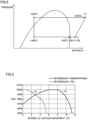
- Fig. 2 shows the relation (a Mollier diagram) between the refrigerant pressure and the enthalpy (specific enthalpy) when refrigeration cycle apparatus 1 is operated to perform a cooling operation.
- the Mollier diagram also shows flow path points P1, P2, P3, P4, P5, P6, P7, and P8 in refrigerant pipe 31 shown in Fig. 1 . Note that each of the flow path points in parentheses indicates a flow path point set when refrigeration cycle apparatus 1 is operated to perform a heating operation.
- the opening degree of expansion valve 9 provided upstream of the flow of the refrigerant with respect to the evaporator is adjusted such that the degree of dryness of the refrigerant having flowed out of the evaporator becomes approximately 1 (one).
- the refrigerant having flowed out of the evaporator and having a degree of dryness of approximately 1 passes through four-way valve 15 and flows through branch pipe 33 into heat absorber 17.
- Heat absorber 17 is in contact with electric component 19a as heat source 19.
- heat absorber 17 heat exchange is performed between the incoming refrigerant and electric component 19a (heat).
- the enthalpy rises while the refrigerant flows from flow path point P6 to flow path point P8, and then, the degree of superheat of the refrigerant having flowed out of heat absorber 17 increases.
- the refrigerant increased in degree of superheat with the degree of dryness of approximately 1 is suctioned into compressor 3.
- Fig. 3 shows the relation between the degree of suction superheat and the value of the COP.
- the horizontal axis represents the degree of suction superheat of the refrigerant suctioned into compressor 3.
- the vertical axis represents the COP of refrigeration cycle apparatus 1.
- a solid line graph A is a graph shown in the case of R290 (propane).
- a dotted line graph B is a graph shown in the case of R32 as a comparative example.
- the COP is represented by a ratio (%) with a score of 100 representing the peak value of the value of the COP in each refrigerant.
- the graph shows that the COP reaches a maximum value, for example, when the degree of suction superheat is about 7 (K), whereas the value of the COP becomes smaller as the degree of suction superheat increases beyond about 7 (K).
- the performance of refrigeration cycle apparatus 1 can be improved by increasing the degree of suction superheat.
- the degree of suction superheat becomes too high, the COP becomes smaller, with the result that the performance of refrigeration cycle apparatus 1 degrades.
- the degree of suction superheat at which the COP reaches a maximum value depends on, for example, the efficiency or the like of compressor 3.
- the flow rate of the refrigerant flowing through heat absorber 17 is regulated by flow rate regulating valve 21 provided in branch pipe 33, and thereby, the degree of suction superheat is adjusted.
- flow rate regulating valve 21 is narrowed to increase the flow rate of the refrigerant that flows into heat absorber 17. This increases the amount of heat exchange between electric component 19a (a heat source) and the refrigerant in heat absorber 17, so that the degree of superheat of the refrigerant having flowed through heat absorber 17 can be increased to the target degree of suction superheat.
- flow rate regulating valve 21 is opened to decrease the flow rate of the refrigerant that flows into heat absorber 17. This decreases the amount of heat exchange between electric component 19a (a heat source) and the refrigerant in heat absorber 17, so that the degree of superheat of the refrigerant having flowed through heat absorber 17 can be decreased to the target degree of suction superheat.
- the degree of suction superheat of the refrigerant suctioned into compressor 3 is regulated by flow rate regulating valve 21, and thereby, the performance of refrigeration cycle apparatus 1 can be maximized.
- heat source 19 is not limited to electric component 19a as long as it is higher in temperature than the refrigerant having flowed through the evaporator (first heat exchanger 5 or second heat exchanger 11).
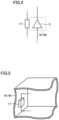
- a compressor housing body 19b that accommodates compressor 3 may be applied as heat source 19.
- a housing 19c that accommodates first heat exchanger 5, second heat exchanger 11 or the like may be applied as heat source 19.
- R290 propane
- the refrigerant is not limited to R290 and any type of refrigerant is applicable as long as the refrigerant has a property that, as the degree of superheat of the refrigerant having flowed through heat absorber 17 increases, the value of the COP of refrigeration cycle apparatus 1 increases and subsequently decreases.
- the flow rate of the refrigerant flowing through heat absorber 17 is regulated by flow rate regulating valve 21, and thereby, the performance of refrigeration cycle apparatus 1 can be maximized.
- the present disclosure is effectively utilized for a refrigeration cycle apparatus using R290 or the like as refrigerant.
- 1 refrigeration cycle apparatus 3 compressor, 5 first heat exchanger, 7 first blower, 9 expansion valve, 11 second heat exchanger, 13 second blower, 15 four-way valve, 17 heat absorber, 19 heat source, 19a electric component, 19b compressor housing body, 19c housing, 21 flow rate regulating valve, 31 refrigerant pipe, 33 branch pipe, P1, P2, P3, P4, P5, P6, P7, P8 flow path point.
Landscapes
- Engineering & Computer Science (AREA)
- Physics & Mathematics (AREA)
- Mechanical Engineering (AREA)
- Thermal Sciences (AREA)
- General Engineering & Computer Science (AREA)
- Compression-Type Refrigeration Machines With Reversible Cycles (AREA)
Abstract
Description
- The present disclosure relates to a refrigeration cycle apparatus.
- For a refrigeration cycle apparatus, a coefficient of performance (COP) is used as an index representing the performance of the refrigeration cycle apparatus. The COP having a larger value means that a larger refrigeration capacity is achieved with smaller consumed compression power. As a method of improving the value of the COP for a refrigeration cycle apparatus, a method of increasing the degree of superheat (the degree of suction superheat) of the refrigerant suctioned into a compressor has been known.
- There has conventionally been a refrigeration cycle apparatus using R32 as refrigerant. In the refrigeration cycle apparatus using R32, however, the value of the COP tends to decrease when the degree of suction superheat is increased.
- In order to solve such a problem, a refrigeration cycle apparatus using R290 (propane) as refrigerant has been proposed. It is considered that R290 allows the degree of suction superheat to increase and also allows the value of the COP to be improved. For example, PTL 1 discloses a refrigeration cycle apparatus using R290 as refrigerant.
- PTL 1:
WO2019/176053 - In the refrigeration cycle apparatus using R290 (propane) as refrigerant, the value of the COP is increased by increasing the degree of suction superheat. However, if the degree of suction superheat is increased too high, the value of the COP tends to become smaller, with the result that the performance of the refrigeration cycle apparatus degrades.
- The present disclosure has been made in order to solve the above-described problems, and an object of the present disclosure is to provide a refrigeration cycle apparatus that can be maximized in performance by adjusting the degree of suction superheat.
- One refrigeration cycle apparatus according to the present disclosure is a refrigeration cycle apparatus using R290 as refrigerant, and includes a compressor, a condenser, an expansion valve, an evaporator, a refrigerant pipe, a heat absorber, a heat source, a branch pipe, and a flow rate regulating valve. The refrigerant pipe is connected to the compressor, the condenser, the expansion valve, the evaporator, and the compressor in sequential order, and the refrigerant flows through the refrigerant pipe. The heat absorber is provided in a portion of the refrigerant pipe, and the portion connects the evaporator and the compressor. The heat source is disposed in contact with the heat absorber and is higher in temperature than the refrigerant having flowed through the evaporator. The branch pipe is connected in parallel with the portion provided with the heat absorber in the refrigerant pipe. The flow rate regulating valve is provided in the branch pipe and configured to regulate a flow rate of the refrigerant.
- Another refrigeration cycle apparatus according to the present disclosure is a refrigeration cycle apparatus including a compressor, a condenser, an expansion valve, and an evaporator, and includes a refrigerant pipe, a heat absorber, a heat source, and a branch pipe. The refrigerant pipe is connected to the compressor, the condenser, the expansion valve, the evaporator, and the compressor in sequential order, and refrigerant flows through the refrigerant pipe. The heat absorber is provided in a portion of the refrigerant pipe, and the portion connects the evaporator and the compressor. The heat source is disposed in contact with the heat absorber. The branch pipe is connected in parallel with the portion provided with the heat absorber in the refrigerant pipe. The refrigerant has a property that, as a degree of superheat of the refrigerant having flowed through the heat absorber increases, a coefficient of performance increases and subsequently decreases. The branch pipe is provided with a flow rate regulating valve configured to regulate a flow rate of the refrigerant.
- According to one refrigeration cycle apparatus of the present disclosure, a heat absorber is provided in the portion between the evaporator and the compressor in the refrigerant pipe. The heat absorber is disposed in contact with the heat source. A branch pipe is connected in parallel with the portion provided with the heat absorber in the refrigerant pipe. The branch pipe is provided with a flow rate regulating valve configured to regulate a flow rate of the refrigerant. Thereby, the flow rate of the refrigerant flowing through the heat absorber can be regulated by the flow rate regulating valve, and thus, the degree of suction superheat of the refrigerant suctioned into the compressor can be adjusted. As a result, the value of the COP of the refrigeration cycle apparatus can be improved.
- According to another refrigeration cycle apparatus of the present disclosure, a heat absorber is provided in a portion between the evaporator and the compressor in the refrigerant pipe. The heat absorber is disposed in contact with the heat source. A branch pipe is connected in parallel with the portion provided with the heat absorber in the refrigerant pipe. The branch pipe is provided with a flow rate regulating valve configured to regulate a flow rate of the refrigerant. The refrigerant has a property that, as the degree of superheat of the refrigerant having flowed through the heat absorber increases, the coefficient of performance increases and subsequently decreases. Thereby, the flow rate of the refrigerant flowing through the heat absorber can be regulated by the flow rate regulating valve, and thus, the degree of suction superheat of the refrigerant suctioned into the compressor can be adjusted. As a result, the value of the COP of the refrigeration cycle apparatus can be improved.
-
-
Fig. 1 is a diagram showing an example of a refrigerant circuit of a refrigeration cycle apparatus according to an embodiment. -
Fig. 2 is a Mollier diagram showing a relation between a refrigerant pressure and an enthalpy in the present embodiment. -
Fig. 3 is a graph showing a relation between a COP and a degree of suction superheat in the present embodiment. -
Fig. 4 is a diagram schematically showing an example of a heat source provided with a heat absorber in the present embodiment. -
Fig. 5 is a diagram schematically showing another example of the heat source provided with the heat absorber in the present embodiment. - A refrigeration cycle apparatus according to an embodiment will be hereinafter described.
Fig. 1 shows an example of a refrigerant circuit of a refrigeration cycle apparatus 1. As shown inFig. 1 , refrigeration cycle apparatus 1 includes acompressor 3, a four-way valve 15, afirst heat exchanger 5, anexpansion valve 9, and asecond heat exchanger 11. Refrigeration cycle apparatus 1 further includes a flowrate regulating valve 21, a heat absorber 17, and a heat source 19. Afirst blower 7 is disposed infirst heat exchanger 5. Asecond blower 13 is disposed insecond heat exchanger 11. Further, as heat source 19, an electric component 19a is disposed that accommodates a control circuit and the like for controlling the operation of refrigeration cycle apparatus 1. -
Compressor 3, four-way valve 15, first heat exchanger 5 (a condenser/an evaporator),expansion valve 9, second heat exchanger 11 (an evaporator /a condenser), andcompressor 3 are connected sequentially in this order by arefrigerant pipe 31 through which refrigerant flows. R290 (propane) is used as refrigerant flowing throughrefrigerant pipe 31 and the like. -
Heat absorber 17 is provided in a portion ofrefrigerant pipe 31 between the evaporator (first heat exchanger 5 or second heat exchanger 11) andcompressor 3.Heat absorber 17 is disposed in contact with electric component 19a serving as a heat source. More specifically,heat absorber 17 is provided in a portion ofrefrigerant pipe 31 that connects four-way valve 15 andcompressor 3. Abranch pipe 33 is connected in parallel with the portion provided with heat absorber 17 inrefrigerant pipe 31.Branch pipe 33 is provided with a flowrate regulating valve 21 configured to regulate the flow rate of the refrigerant. Refrigeration cycle apparatus 1 according to the present embodiment is configured as described above. - As an operation of refrigeration cycle apparatus 1 described above, a heating operation (see dotted arrows) will be first described. In this case,
compressor 3, four-way valve 15,second heat exchanger 11,expansion valve 9,first heat exchanger 5, four-way valve 15,heat absorber 17, andcompressor 3 are connected sequentially in this order byrefrigerant pipe 31. By drivingcompressor 3, high-temperature and high-pressure gas refrigerant is discharged fromcompressor 3. The discharged high-temperature and high-pressure gas refrigerant (of a single phase) flows intosecond heat exchanger 11 through four-way valve 15. In this case,second heat exchanger 11 functions as a condenser. - In
second heat exchanger 11 functioning as a condenser, heat exchange is performed between the incoming gas refrigerant and the air supplied bysecond blower 13. The high-temperature and high-pressure gas refrigerant is condensed into high-pressure liquid refrigerant (of a single phase). By this heat exchange, for example, a room is heated. The high-pressure liquid refrigerant delivered fromsecond heat exchanger 11 is converted byexpansion valve 9 into low-pressure gas-liquid two-phase refrigerant. The two-phase refrigerant flows intofirst heat exchanger 5. In this case,first heat exchanger 5 functions as an evaporator. - In
first heat exchanger 5 functioning as an evaporator, heat exchange is performed between the incoming two-phase refrigerant and the air supplied byfirst blower 7. Then, liquid refrigerant is evaporated from the two-phase refrigerant, which results in low-pressure gas refrigerant (of a single phase). The low-pressure gas refrigerant delivered fromfirst heat exchanger 5 passes through four-way valve 15 and flows intocompressor 3 throughheat absorber 17 or flowrate regulating valve 21. The low-pressure gas refrigerant flowing intocompressor 3 is compressed into high-temperature and high-pressure gas refrigerant, and then discharged fromcompressor 3 again. This cycle is thereafter repeated. The functions of flowrate regulating valve 21 andheat absorber 17 will be described later. - The following describes the case of a cooling operation (see solid arrows). In this case,
compressor 3, four-way valve 15,first heat exchanger 5,expansion valve 9,second heat exchanger 11, four-way valve 15,heat absorber 17, andcompressor 3 are connected sequentially in this order byrefrigerant pipe 31. By drivingcompressor 3, high-temperature and high-pressure gas refrigerant is discharged fromcompressor 3. The discharged high-temperature and high-pressure gas refrigerant (of a single phase) flows intofirst heat exchanger 5 through four-way valve 15. In this case,first heat exchanger 5 functions as a condenser. Infirst heat exchanger 5 functioning as a condenser, heat exchange is performed between the incoming refrigerant and the air supplied byfirst blower 7. The high-temperature and high-pressure gas refrigerant is condensed into high-pressure liquid refrigerant (of a single phase). - The high-pressure liquid refrigerant delivered from
first heat exchanger 5 is converted byexpansion valve 9 into low-pressure gas-liquid two-phase refrigerant. The two-phase refrigerant flows intosecond heat exchanger 11. Insecond heat exchanger 11, heat exchange is performed between the incoming two-phase refrigerant and the air supplied bysecond blower 13. Then, liquid refrigerant is evaporated from the two-phase refrigerant, which results in low-pressure gas refrigerant (of a single phase). By this heat exchange, for example, a room is cooled. - The low-pressure gas refrigerant delivered from
second heat exchanger 11 passes through four-way valve 15 and flows intocompressor 3 throughheat absorber 17 or flowrate regulating valve 21. The low-pressure gas refrigerant flowing intocompressor 3 is compressed into high-temperature and high-pressure gas refrigerant, and then discharged fromcompressor 3 again. This cycle is thereafter repeated. - In the above-described refrigeration cycle apparatus 1 using R290 (propane) as refrigerant, the degree of suction superheat of the refrigerant suctioned into
compressor 3 is adjusted, and thereby, the value of the COP can be improved, which will be hereinafter described. - First,
Fig. 2 shows the relation (a Mollier diagram) between the refrigerant pressure and the enthalpy (specific enthalpy) when refrigeration cycle apparatus 1 is operated to perform a cooling operation. The Mollier diagram also shows flow path points P1, P2, P3, P4, P5, P6, P7, and P8 inrefrigerant pipe 31 shown inFig. 1 . Note that each of the flow path points in parentheses indicates a flow path point set when refrigeration cycle apparatus 1 is operated to perform a heating operation. - During each of the heating operation and the cooling operation, in order to maintain the heat exchange performance of the evaporator (
first heat exchanger 5/second heat exchanger 11), the opening degree ofexpansion valve 9 provided upstream of the flow of the refrigerant with respect to the evaporator is adjusted such that the degree of dryness of the refrigerant having flowed out of the evaporator becomes approximately 1 (one). - The refrigerant having flowed out of the evaporator and having a degree of dryness of approximately 1 passes through four-
way valve 15 and flows throughbranch pipe 33 intoheat absorber 17.Heat absorber 17 is in contact with electric component 19a as heat source 19. Inheat absorber 17, heat exchange is performed between the incoming refrigerant and electric component 19a (heat). Thereby, the enthalpy rises while the refrigerant flows from flow path point P6 to flow path point P8, and then, the degree of superheat of the refrigerant having flowed out ofheat absorber 17 increases. Thus, the refrigerant increased in degree of superheat with the degree of dryness of approximately 1 is suctioned intocompressor 3. -
Fig. 3 shows the relation between the degree of suction superheat and the value of the COP. The horizontal axis represents the degree of suction superheat of the refrigerant suctioned intocompressor 3. The vertical axis represents the COP of refrigeration cycle apparatus 1. A solid line graph A is a graph shown in the case of R290 (propane). A dotted line graph B is a graph shown in the case of R32 as a comparative example. The COP is represented by a ratio (%) with a score of 100 representing the peak value of the value of the COP in each refrigerant. - As shown by graph A, when the refrigerant is R290, the value of the COP gradually increases as the degree of suction superheat increases from 0 (K). On the other hand, as shown by graph B, when the refrigerant is R32, the value of the COP decreases as the degree of suction superheat increases from 0 (K). This shows that, in the case where the refrigerant is R290, the degree of suction superheat is increased and thereby the value of the COP can be improved. Examples of the refrigerant showing the same tendency as that of refrigerant R32 shown by graph B include HFC refrigerant.
- In the case where the refrigerant is R290, however, the graph shows that the COP reaches a maximum value, for example, when the degree of suction superheat is about 7 (K), whereas the value of the COP becomes smaller as the degree of suction superheat increases beyond about 7 (K). In other words, in the case of R290, the performance of refrigeration cycle apparatus 1 can be improved by increasing the degree of suction superheat. However, when the degree of suction superheat becomes too high, the COP becomes smaller, with the result that the performance of refrigeration cycle apparatus 1 degrades. In actual refrigeration cycle apparatus 1, the degree of suction superheat at which the COP reaches a maximum value depends on, for example, the efficiency or the like of
compressor 3. - Thus, in refrigeration cycle apparatus 1 as described above, the flow rate of the refrigerant flowing through
heat absorber 17 is regulated by flowrate regulating valve 21 provided inbranch pipe 33, and thereby, the degree of suction superheat is adjusted. - When the degree of superheat of the refrigerant having flowed through
heat absorber 17 is lower than the target degree of suction superheat at which the COP reaches the maximum value, flowrate regulating valve 21 is narrowed to increase the flow rate of the refrigerant that flows intoheat absorber 17. This increases the amount of heat exchange between electric component 19a (a heat source) and the refrigerant inheat absorber 17, so that the degree of superheat of the refrigerant having flowed throughheat absorber 17 can be increased to the target degree of suction superheat. - On the other hand, when the degree of superheat of the refrigerant having flowed through
heat absorber 17 is higher than the target degree of suction superheat at which the COP reaches the maximum value, flowrate regulating valve 21 is opened to decrease the flow rate of the refrigerant that flows intoheat absorber 17. This decreases the amount of heat exchange between electric component 19a (a heat source) and the refrigerant inheat absorber 17, so that the degree of superheat of the refrigerant having flowed throughheat absorber 17 can be decreased to the target degree of suction superheat. - Thus, in refrigeration cycle apparatus 1 as described above, the degree of suction superheat of the refrigerant suctioned into
compressor 3 is regulated by flowrate regulating valve 21, and thereby, the performance of refrigeration cycle apparatus 1 can be maximized. - In refrigeration cycle apparatus 1 as described above, electric component 19a is cited as an example of heat source 19. Heat source 19 is not limited to electric component 19a as long as it is higher in temperature than the refrigerant having flowed through the evaporator (
first heat exchanger 5 or second heat exchanger 11). For example, as shown inFig. 4 , a compressor housing body 19b that accommodatescompressor 3 may be applied as heat source 19. Alternatively, as shown inFig. 5 , a housing 19c that accommodatesfirst heat exchanger 5,second heat exchanger 11 or the like may be applied as heat source 19. - Further, in the above description of refrigeration cycle apparatus 1, R290 (propane) is cited as an example of refrigerant. The refrigerant is not limited to R290 and any type of refrigerant is applicable as long as the refrigerant has a property that, as the degree of superheat of the refrigerant having flowed through
heat absorber 17 increases, the value of the COP of refrigeration cycle apparatus 1 increases and subsequently decreases. Also, the flow rate of the refrigerant flowing throughheat absorber 17 is regulated by flowrate regulating valve 21, and thereby, the performance of refrigeration cycle apparatus 1 can be maximized. - The embodiments disclosed herein are merely by way of example and not limited thereto. The present disclosure is defined by the scope of the claims, rather than the scope described above, and is intended to include any modifications within the meaning and scope equivalent to the terms of the claims.
- The present disclosure is effectively utilized for a refrigeration cycle apparatus using R290 or the like as refrigerant.
- 1 refrigeration cycle apparatus, 3 compressor, 5 first heat exchanger, 7 first blower, 9 expansion valve, 11 second heat exchanger, 13 second blower, 15 four-way valve, 17 heat absorber, 19 heat source, 19a electric component, 19b compressor housing body, 19c housing, 21 flow rate regulating valve, 31 refrigerant pipe, 33 branch pipe, P1, P2, P3, P4, P5, P6, P7, P8 flow path point.
Claims (7)
- A refrigeration cycle apparatus using R290 as refrigerant, the refrigeration cycle apparatus comprising:a compressor, a condenser, an expansion valve, and an evaporator;a refrigerant pipe connected to the compressor, the condenser, the expansion valve, the evaporator, and the compressor in sequential order, the refrigerant flowing through the refrigerant pipe;a heat absorber provided in a portion of the refrigerant pipe, the portion connecting the evaporator and the compressor;a heat source disposed in contact with the heat absorber, the heat source being higher in temperature than the refrigerant having flowed through the evaporator;a branch pipe connected in parallel with the portion provided with the heat absorber in the refrigerant pipe; anda flow rate regulating valve provided in the branch pipe and configured to regulate a flow rate of the refrigerant.
- The refrigeration cycle apparatus according to claim 1, wherein the heat source has an electric component box that accommodates an electric component.
- The refrigeration cycle apparatus according to claim 1, wherein the heat source comprises the compressor.
- The refrigeration cycle apparatus according to claim 1, comprising a housing that accommodates the compressor, wherein
the heat source has the housing. - The refrigeration cycle apparatus according to any one of claims 1 to 4, whereinthe condenser and the evaporator are provided as a first heat exchanger and a second heat exchanger,the refrigeration cycle apparatus comprises a four-way valve configured to switch an operation betweena first operation in which the first heat exchanger is operated as the condenser and the second heat exchanger is operated as the evaporator, anda second operation in which the second heat exchanger is operated as the condenser and the first heat exchanger is operated as the evaporator, andthe portion provided with the heat absorber in the refrigerant pipe is disposed between the four-way valve and the compressor.
- A refrigeration cycle apparatus comprising a compressor, a condenser, an expansion valve, and an evaporator, the refrigeration cycle apparatus comprising:a refrigerant pipe connected to the compressor, the condenser, the expansion valve, the evaporator, and the compressor in sequential order, refrigerant flowing through the refrigerant pipe;a heat absorber provided in a portion of the refrigerant pipe, the portion connecting the evaporator and the compressor;a heat source disposed in contact with the heat absorber; anda branch pipe connected in parallel with the portion provided with the heat absorber in the refrigerant pipe, whereinthe refrigerant has a property that, as a degree of superheat of the refrigerant having flowed through the heat absorber increases, a coefficient of performance increases and subsequently decreases, andthe branch pipe is provided with a flow rate regulating valve configured to regulate a flow rate of the refrigerant.
- The refrigeration cycle apparatus according to claim 6, wherein the refrigerant contains R290.
Applications Claiming Priority (1)
| Application Number | Priority Date | Filing Date | Title |
|---|---|---|---|
| PCT/JP2020/021779 WO2021245789A1 (en) | 2020-06-02 | 2020-06-02 | Refrigeration cycle device |
Publications (2)
| Publication Number | Publication Date |
|---|---|
| EP4160110A1 true EP4160110A1 (en) | 2023-04-05 |
| EP4160110A4 EP4160110A4 (en) | 2023-09-20 |
Family
ID=78830172
Family Applications (1)
| Application Number | Title | Priority Date | Filing Date |
|---|---|---|---|
| EP20939438.6A Withdrawn EP4160110A4 (en) | 2020-06-02 | 2020-06-02 | REFRIGERANT CIRCUIT DEVICE |
Country Status (5)
| Country | Link |
|---|---|
| US (1) | US12140357B2 (en) |
| EP (1) | EP4160110A4 (en) |
| JP (1) | JP7367213B2 (en) |
| CN (1) | CN115552186A (en) |
| WO (1) | WO2021245789A1 (en) |
Family Cites Families (12)
| Publication number | Priority date | Publication date | Assignee | Title |
|---|---|---|---|---|
| JPH11193967A (en) * | 1997-12-26 | 1999-07-21 | Zexel:Kk | Refrigerating cycle |
| JP4687093B2 (en) | 2004-12-13 | 2011-05-25 | ダイキン工業株式会社 | Air conditioner |
| CN101666559B (en) * | 2006-03-27 | 2012-04-04 | 三菱电机株式会社 | Refrigerating and air-conditioning plant |
| JP2008057875A (en) * | 2006-08-31 | 2008-03-13 | Mitsubishi Electric Corp | Refrigeration cycle equipment |
| JP2009264710A (en) | 2008-04-30 | 2009-11-12 | Daikin Ind Ltd | Heat pump device |
| JP2012167824A (en) | 2009-06-19 | 2012-09-06 | Daikin Industries Ltd | Refrigerator |
| JP2011122779A (en) | 2009-12-11 | 2011-06-23 | Toshiba Carrier Corp | Refrigerating cycle device |
| CN103162475B (en) * | 2013-03-22 | 2015-04-15 | 青岛海信日立空调系统有限公司 | Heat dissipation circulating system of air conditioner |
| JP6005024B2 (en) * | 2013-11-12 | 2016-10-12 | 三菱電機株式会社 | Refrigeration cycle equipment |
| JP6902390B2 (en) | 2017-04-27 | 2021-07-14 | 日立ジョンソンコントロールズ空調株式会社 | Refrigeration cycle equipment |
| SG11202008625TA (en) | 2018-03-09 | 2020-10-29 | Mitsubishi Electric Corp | Refrigeration cycle apparatus |
| JP6945722B2 (en) | 2018-03-15 | 2021-10-06 | 三菱電機株式会社 | Refrigeration cycle equipment |
-
2020
- 2020-06-02 CN CN202080100684.6A patent/CN115552186A/en active Pending
- 2020-06-02 EP EP20939438.6A patent/EP4160110A4/en not_active Withdrawn
- 2020-06-02 WO PCT/JP2020/021779 patent/WO2021245789A1/en not_active Ceased
- 2020-06-02 US US17/920,092 patent/US12140357B2/en active Active
- 2020-06-02 JP JP2022529176A patent/JP7367213B2/en active Active
Also Published As
| Publication number | Publication date |
|---|---|
| US20230160616A1 (en) | 2023-05-25 |
| WO2021245789A1 (en) | 2021-12-09 |
| EP4160110A4 (en) | 2023-09-20 |
| CN115552186A (en) | 2022-12-30 |
| JP7367213B2 (en) | 2023-10-23 |
| US12140357B2 (en) | 2024-11-12 |
| JPWO2021245789A1 (en) | 2021-12-09 |
Similar Documents
| Publication | Publication Date | Title |
|---|---|---|
| CN110337570B (en) | Air conditioner | |
| EP3144606B1 (en) | Air conditioner | |
| JPH07234038A (en) | Multi-room air conditioner and its operating method | |
| JP5386141B2 (en) | Heat pump device control method, heat pump device outdoor unit and heat pump device | |
| CN109869941B (en) | Heat pump system, air suction superheat degree and vapor-liquid separator accumulated liquid evaporation control method | |
| JP2006300370A (en) | Air conditioner | |
| US11041667B2 (en) | Refrigeration cycle apparatus | |
| KR100822432B1 (en) | Air Conditioner with Auxiliary Heat Exchanger | |
| CN114087718B (en) | Air conditioner, air conditioner control method, control device and readable storage medium | |
| WO2014129361A1 (en) | Air conditioner | |
| JPH11270918A (en) | Refrigeration equipment | |
| WO2023190140A1 (en) | Air conditioner | |
| KR100505238B1 (en) | Air-conditioner | |
| US12140357B2 (en) | Refrigeration cycle apparatus and method for controlling refrigeration cycle apparatus | |
| EP4589215A1 (en) | Air conditioner | |
| CN115962529B (en) | Air conditioning system, spray enthalpy control method of air conditioning system, and readable storage medium | |
| EP4467893A1 (en) | Air conditioner | |
| JP7750099B2 (en) | air conditioner | |
| KR101321543B1 (en) | Air conditioning system | |
| JP2000213819A (en) | Refrigerating cycle | |
| US12339026B2 (en) | Air-conditioner | |
| KR100826027B1 (en) | Refrigerant circulation system | |
| JP7474911B1 (en) | Refrigeration Cycle Equipment | |
| JP2012017878A (en) | Air conditioning device | |
| CN119164026A (en) | An air conditioning system |
Legal Events
| Date | Code | Title | Description |
|---|---|---|---|
| STAA | Information on the status of an ep patent application or granted ep patent |
Free format text: STATUS: THE INTERNATIONAL PUBLICATION HAS BEEN MADE |
|
| PUAI | Public reference made under article 153(3) epc to a published international application that has entered the european phase |
Free format text: ORIGINAL CODE: 0009012 |
|
| STAA | Information on the status of an ep patent application or granted ep patent |
Free format text: STATUS: REQUEST FOR EXAMINATION WAS MADE |
|
| 17P | Request for examination filed |
Effective date: 20221025 |
|
| AK | Designated contracting states |
Kind code of ref document: A1 Designated state(s): AL AT BE BG CH CY CZ DE DK EE ES FI FR GB GR HR HU IE IS IT LI LT LU LV MC MK MT NL NO PL PT RO RS SE SI SK SM TR |
|
| DAV | Request for validation of the european patent (deleted) | ||
| DAX | Request for extension of the european patent (deleted) | ||
| A4 | Supplementary search report drawn up and despatched |
Effective date: 20230821 |
|
| RIC1 | Information provided on ipc code assigned before grant |
Ipc: F25B 41/39 20210101ALI20230815BHEP Ipc: F25B 41/22 20210101ALI20230815BHEP Ipc: F25B 5/04 20060101ALI20230815BHEP Ipc: F25B 1/00 20060101ALI20230815BHEP Ipc: F25B 13/00 20060101AFI20230815BHEP |
|
| STAA | Information on the status of an ep patent application or granted ep patent |
Free format text: STATUS: THE APPLICATION HAS BEEN WITHDRAWN |
|
| 18W | Application withdrawn |
Effective date: 20250210 |