EP4160102A1 - Oil return control method for multi-split system - Google Patents
Oil return control method for multi-split system Download PDFInfo
- Publication number
- EP4160102A1 EP4160102A1 EP21800140.2A EP21800140A EP4160102A1 EP 4160102 A1 EP4160102 A1 EP 4160102A1 EP 21800140 A EP21800140 A EP 21800140A EP 4160102 A1 EP4160102 A1 EP 4160102A1
- Authority
- EP
- European Patent Office
- Prior art keywords
- oil return
- opening degree
- expansion valve
- indoor unit
- smax
- Prior art date
- Legal status (The legal status is an assumption and is not a legal conclusion. Google has not performed a legal analysis and makes no representation as to the accuracy of the status listed.)
- Granted
Links
Images

Classifications
-
- F—MECHANICAL ENGINEERING; LIGHTING; HEATING; WEAPONS; BLASTING
- F24—HEATING; RANGES; VENTILATING
- F24F—AIR-CONDITIONING; AIR-HUMIDIFICATION; VENTILATION; USE OF AIR CURRENTS FOR SCREENING
- F24F11/00—Control or safety arrangements
- F24F11/30—Control or safety arrangements for purposes related to the operation of the system, e.g. for safety or monitoring
-
- F—MECHANICAL ENGINEERING; LIGHTING; HEATING; WEAPONS; BLASTING
- F25—REFRIGERATION OR COOLING; COMBINED HEATING AND REFRIGERATION SYSTEMS; HEAT PUMP SYSTEMS; MANUFACTURE OR STORAGE OF ICE; LIQUEFACTION SOLIDIFICATION OF GASES
- F25B—REFRIGERATION MACHINES, PLANTS OR SYSTEMS; COMBINED HEATING AND REFRIGERATION SYSTEMS; HEAT PUMP SYSTEMS
- F25B31/00—Compressor arrangements
- F25B31/002—Lubrication
- F25B31/004—Lubrication oil recirculating arrangements
-
- F—MECHANICAL ENGINEERING; LIGHTING; HEATING; WEAPONS; BLASTING
- F24—HEATING; RANGES; VENTILATING
- F24F—AIR-CONDITIONING; AIR-HUMIDIFICATION; VENTILATION; USE OF AIR CURRENTS FOR SCREENING
- F24F11/00—Control or safety arrangements
- F24F11/50—Control or safety arrangements characterised by user interfaces or communication
- F24F11/61—Control or safety arrangements characterised by user interfaces or communication using timers
-
- F—MECHANICAL ENGINEERING; LIGHTING; HEATING; WEAPONS; BLASTING
- F24—HEATING; RANGES; VENTILATING
- F24F—AIR-CONDITIONING; AIR-HUMIDIFICATION; VENTILATION; USE OF AIR CURRENTS FOR SCREENING
- F24F11/00—Control or safety arrangements
- F24F11/62—Control or safety arrangements characterised by the type of control or by internal processing, e.g. using fuzzy logic, adaptive control or estimation of values
- F24F11/63—Electronic processing
- F24F11/64—Electronic processing using pre-stored data
-
- F—MECHANICAL ENGINEERING; LIGHTING; HEATING; WEAPONS; BLASTING
- F24—HEATING; RANGES; VENTILATING
- F24F—AIR-CONDITIONING; AIR-HUMIDIFICATION; VENTILATION; USE OF AIR CURRENTS FOR SCREENING
- F24F11/00—Control or safety arrangements
- F24F11/70—Control systems characterised by their outputs; Constructional details thereof
-
- F—MECHANICAL ENGINEERING; LIGHTING; HEATING; WEAPONS; BLASTING
- F25—REFRIGERATION OR COOLING; COMBINED HEATING AND REFRIGERATION SYSTEMS; HEAT PUMP SYSTEMS; MANUFACTURE OR STORAGE OF ICE; LIQUEFACTION SOLIDIFICATION OF GASES
- F25B—REFRIGERATION MACHINES, PLANTS OR SYSTEMS; COMBINED HEATING AND REFRIGERATION SYSTEMS; HEAT PUMP SYSTEMS
- F25B49/00—Arrangement or mounting of control or safety devices
- F25B49/02—Arrangement or mounting of control or safety devices for compression type machines, plants or systems
-
- F—MECHANICAL ENGINEERING; LIGHTING; HEATING; WEAPONS; BLASTING
- F25—REFRIGERATION OR COOLING; COMBINED HEATING AND REFRIGERATION SYSTEMS; HEAT PUMP SYSTEMS; MANUFACTURE OR STORAGE OF ICE; LIQUEFACTION SOLIDIFICATION OF GASES
- F25B—REFRIGERATION MACHINES, PLANTS OR SYSTEMS; COMBINED HEATING AND REFRIGERATION SYSTEMS; HEAT PUMP SYSTEMS
- F25B2500/00—Problems to be solved
- F25B2500/16—Lubrication
-
- F—MECHANICAL ENGINEERING; LIGHTING; HEATING; WEAPONS; BLASTING
- F25—REFRIGERATION OR COOLING; COMBINED HEATING AND REFRIGERATION SYSTEMS; HEAT PUMP SYSTEMS; MANUFACTURE OR STORAGE OF ICE; LIQUEFACTION SOLIDIFICATION OF GASES
- F25B—REFRIGERATION MACHINES, PLANTS OR SYSTEMS; COMBINED HEATING AND REFRIGERATION SYSTEMS; HEAT PUMP SYSTEMS
- F25B2600/00—Control issues
- F25B2600/25—Control of valves
- F25B2600/2513—Expansion valves
-
- F—MECHANICAL ENGINEERING; LIGHTING; HEATING; WEAPONS; BLASTING
- F25—REFRIGERATION OR COOLING; COMBINED HEATING AND REFRIGERATION SYSTEMS; HEAT PUMP SYSTEMS; MANUFACTURE OR STORAGE OF ICE; LIQUEFACTION SOLIDIFICATION OF GASES
- F25B—REFRIGERATION MACHINES, PLANTS OR SYSTEMS; COMBINED HEATING AND REFRIGERATION SYSTEMS; HEAT PUMP SYSTEMS
- F25B5/00—Compression machines, plants or systems, with several evaporator circuits, e.g. for varying refrigerating capacity
- F25B5/02—Compression machines, plants or systems, with several evaporator circuits, e.g. for varying refrigerating capacity arranged in parallel
Definitions
- the present disclosure belongs to the technical field of air conditioning, and specifically provides an oil return control method for a multi-connection system.
- a multi-connection system usually consists of a plurality of indoor units and at least one outdoor unit. During the actual operation, some indoor units are in a shutdown or standby state. If an expansion valve of the shutdown or standby indoor unit is closed, a lubricating oil in connecting pipes and heat exchanger of the indoor unit cannot be circulated into the system. As the time elapses, there will be more and more lubricating oil in the indoor unit, causing the compressor to suffer severe wear due to lack of the lubricating oil or causing damage to the compressor due to overheating. In order to ensure a normal operation of the multi-connection system, oil return control is required so that the lubricating oil can be normally circulated into the system.
- the oil is usually returned according to a fixed cycle.
- the expansion valve is opened by a fixed opening degree, and the system terminates the oil return after an oil return operation time is reached.
- the traditional oil return control methods have not fundamentally solved the problem of insufficient lubricating oil in the compressor, and may also cause the problem of poor overall heat exchange performance of the system due to the insufficient amount of refrigerant in the normally turned-on indoor units. That is, the traditional oil return control methods cannot give considerations to both the oil return effect and the heat exchange performance of the system.
- the present disclosure provides an oil return control method for a multi-connection system.
- the multi-connection system includes a plurality of indoor units, at least one of which is not turned on, and the oil return control method includes: determining an oil storage quantity q of the indoor units; determining a system oil return time T of the multi-connection system; determining a current opening degree k of an expansion valve of one indoor unit that is not turned on according to the oil storage quantity q and the system oil return time T; comparing the current opening degree k with a maximum opening degree threshold k smax and a minimum opening degree threshold k smin ; selectively adjusting the opening degree of the expansion valve according to a comparison result, and keeping the expansion valve operating at the adjusted opening degree for the system oil return time T.
- the step of "selectively adjusting the opening degree of the expansion valve according to a comparison result, and keeping the expansion valve operating at the adjusted opening degree for the system oil return time T" specifically includes: keeping the expansion valve operating at the current opening degree k for the system oil return time T if k smin ⁇ k ⁇ k smax , and then returning to the step of determining q.
- the step of "selectively adjusting the opening degree of the expansion valve according to a comparison result, and keeping the expansion valve operating at the adjusted opening degree for the system oil return time T" specifically includes: adjusting the opening degree of the expansion valve to k smax if k>k smax , keeping the expansion valve operating at the adjusted opening degree for the system oil return time T, and then returning to the step of determining q.
- the expansion valve before returning to the step of determining q, the expansion valve is kept operating at the adjusted opening degree for an oil return interval time Ti.
- the step of "keeping the expansion valve operating at the adjusted opening degree for an oil return interval time T i " specifically includes: acquiring a shutdown time t sp of the indoor unit; and judging whether the shutdown time t sp is larger than a maximum shutdown time threshold t spmax ; if yes, it means that the expansion valve has operated at the adjusted opening degree for the oil return interval time Ti.
- the oil return control method for the multi-connection system includes: determining an oil storage quantity q of the indoor units; determining a system oil return time T of the multi-connection system; determining a current opening degree k of an expansion valve of one indoor unit that is not turned on according to the oil storage quantity q and the system oil return time T; comparing the current opening degree k with a maximum opening degree threshold k smax and a minimum opening degree threshold k smin ; selectively adjusting the opening degree of the expansion valve according to a comparison result, and keeping the expansion valve operating at the adjusted opening degree for the system oil return time T.
- the oil return control method of the present disclosure can precisely control the opening degree of the expansion valve and the oil return time of each indoor unit that is not turned on, so that at the same time of providing sufficient lubricating oil to the compressor, it can also be ensured that there is sufficient amount of refrigerant in the normally turned-on indoor units, thus giving considerations to both the oil return effect and the heat exchange performance of the system.
- a “controller” may include hardware, software, or a combination thereof.
- a module may include hardware circuits, various suitable sensors, communication ports and memories, and may also include software parts, such as program codes, or a combination of software and hardware.
- FIG. 1 a typical structure of a multi-connection system will be first briefly introduced with reference to FIG. 1 .
- the dotted line “- - - " in FIG. 1 represents liquid pipes
- the solid line “-" in FIG. 1 represents gas pipes.
- a multi-connection system includes an outdoor unit and n indoor units.
- Each of the indoor units is connected to the outdoor unit through a gas pipe and a liquid pipe to form a refrigerant circulation system, and each of the indoor units further includes an expansion valve VE.
- the expansion valve VE is arranged on the liquid pipe between the outdoor unit and the corresponding indoor unit, and is configured to adjust the amount of refrigerant flowing through the indoor unit.
- the lubricating oil also circulates with the refrigerant in the system so as to lubricate and cool inner components of a compressor.
- indoor units in the shutdown or standby state are collectively referred to as indoor units that are not turned on herein.
- an opening degree of the expansion valves VE of the indoor units that are not turned on is adjusted to a fixed value within a preset period of time, so that the lubricating oil accumulated in the indoor units that are not turned on flows back into the compressor with the refrigerant, which is called an oil return control process of the multi-connection system.
- the present disclosure provides an oil return control method for a multi-connection system, which can precisely control the opening degree of the expansion valve of each indoor unit that is not turned on and the oil return time thereof, so that at the same time of providing sufficient lubricating oil to the compressor, it can also be ensured that there is sufficient amount of refrigerant in the normally turned-on indoor units, thus giving considerations to both the oil return effect and the heat exchange performance of the system.
- the main step flow of the oil return control method of the present disclosure includes:
- the expansion valve of the turned-on indoor unit is always in an open state before the oil is returned.
- the opening degrees of the expansion valves of all the turned-on indoor units are normally adjusted according to a control logic before the oil return.
- a detailed step flow of the oil return control method of the present disclosure includes the following steps.
- Step S100 determining an oil storage quantity q of all the indoor units.
- step S 100 the oil storage quantity q of the indoor units is determined according to formula (1).
- q P ⁇ t sp ⁇ P d ⁇ P s ⁇ R o
- P represents a capacity horsepower of the indoor unit
- t sp represents the shutdown time of the indoor unit
- P d represents a system high pressure of the multi-connection system
- P s represents a system low pressure of the multi-connection system
- R o represents an oil storage coefficient of the indoor unit.
- P represents the capacity horsepower of the indoor unit. This value is a performance parameter of the indoor unit, which has been clearly set at the factory and can be acquired directly when needed, without additional calculation.
- t sp represents the shutdown time of the indoor unit. The shutdown time t sp of each indoor unit is stored in a controller of the multi-connection system, and can be read directly when needed.
- P d and P s represent the system high pressure and system low pressure of the multi-connection system respectively. These two specific values can be collected by two pressure sensors installed on the outdoor unit, and then transmitted to the controller in a wired or wireless manner for storage. Also, they can be read directly when needed.
- R o represents the oil storage coefficient of the indoor unit, and this value depends on an ambient temperature T ai of the indoor unit, a saturation temperature T pd corresponding to the system high pressure and a saturation temperature T ps corresponding to the system low pressure under different working conditions of the system.
- Table 1 shows the oil storage coefficient R o obtained under different working conditions of the indoor unit through experimental verification, and an appropriate value can be chosen from Table 1 according to the actual working conditions of the indoor unit during calculation.
- Step S200 determining a system oil return time T of the multi-connection system.
- step S200 specifically includes: Step S201: acquiring the maximum oil storage quantity q max of the indoor unit.
- the controller of the multi-connection system calculates and stores the oil storage quantity q of each indoor unit according to the aforementioned formula (1).
- the oil storage quantity q of the indoor unit varies according to the different working condition of the indoor unit.
- the controller traverses all the oil storage quantities q of the indoor unit that have been stored, finds out the maximum oil storage quantity q max therefrom and reads it directly.
- Step S202 judging whether the maximum oil storage quantity q max is larger than the maximum oil storage quantity threshold q smax ; if yes, the process proceeds to step S203; otherwise, the process proceeds to step S204.
- Step S203 determining the system oil return time T as the maximum oil return time threshold T smax .
- the values of the maximum oil storage quantity threshold q smax and the maximum oil return time threshold T smax depend on various performance parameters of the indoor unit, and they can be set by those skilled in the art according to the specific performance parameters of the indoor unit.
- step S300 After the oil storage quantity q of the indoor unit and the system oil return time T are determined, with continued reference to FIG. 2 , the oil return control method proceeds to step S300.
- q smax , k smax and a minimum opening degree threshold k smin that will appear in subsequent steps depend on various performance parameters of the indoor unit, and they can be set by those skilled in the art according to the specific performance parameters of the indoor unit.
- T smax depends on the actual working parameters of the multi-connection system, and it can be set by those skilled in the art according to the actual situation.
- Step S400 comparing the current opening degree k with the maximum opening degree threshold k smax and a minimum opening degree threshold k smin .
- Step S500 selectively adjusting the opening degree of the expansion valve according to a comparison result, and keeping the expansion valve operating at the adjusted opening degree for the system oil return time T.
- Step S502 adjusting the opening degree of the expansion valve to k smin , and keeping the expansion valve operating at the adjusted opening degree for the indoor unit oil return time t.
- Step S503 adjusting the opening degree of the expansion valve to zero, and keeping the expansion valve operating at the adjusted opening degree for a time T-t; then the process returns to the step of determining q.
- step S504 the process proceeds to step S504 of keeping the expansion valve operating at the current opening degree k for the system oil return time T, and then the process returns to the step of determining q.
- step S505 the process proceeds to step S505 of adjusting the opening degree of the expansion valve to k smax and keeping the expansion valve operating at the adjusted opening degree for the system oil return time T, and then the process returns to the step of determining q.
- the oil return control method further includes: Step S600: keeping the expansion valve operating at the adjusted opening degree for an oil return interval time Ti.
- the present disclosure will provide two methods of judging whether the expansion valve has operated at the adjusted opening degree for the oil return interval time T i , and the two methods will be described in detail below with reference to FIGS. 5 and 6 . It should be noted that in order to improve readability, the following two methods are distinguished by different step labels. Specifically, steps of the first method are denoted by a label S600, and steps of the second method are denoted by a label S600'.
- step S600 of the first method specifically includes:
- Step S602 judging whether the total oil storage quantity Q is larger than a maximum total oil storage quantity threshold Q smax ; if yes, the process proceeds to step S603; otherwise, the process returns to step S601.
- Step S603 meaning that the expansion valve has operated at the adjusted opening degree for the oil return interval time Ti.
- step S600' of the second method specifically includes:
- the method for judging whether the expansion valve has operated at the adjusted opening degree for the oil return interval time T i is not limited to the above two methods, and those skilled in the art can also use other conventional means to judge.
- the present disclosure also provides a multi-connection air conditioning system including a controller, and the controller is configured to be capable of executing the above refrigerant flow control method.
- the basic functional components constituting the multi-connection air conditioning system and the working principle are basically the same as those in the prior art, and can be realized by those skilled in the art completely based on the prior art, so a repeated description thereof will not be given herein.
Landscapes
- Engineering & Computer Science (AREA)
- Mechanical Engineering (AREA)
- General Engineering & Computer Science (AREA)
- Chemical & Material Sciences (AREA)
- Combustion & Propulsion (AREA)
- Physics & Mathematics (AREA)
- Signal Processing (AREA)
- Thermal Sciences (AREA)
- Human Computer Interaction (AREA)
- Fuzzy Systems (AREA)
- Mathematical Physics (AREA)
- Air Conditioning Control Device (AREA)
Abstract
Description
- The present disclosure belongs to the technical field of air conditioning, and specifically provides an oil return control method for a multi-connection system.
- A multi-connection system usually consists of a plurality of indoor units and at least one outdoor unit. During the actual operation, some indoor units are in a shutdown or standby state. If an expansion valve of the shutdown or standby indoor unit is closed, a lubricating oil in connecting pipes and heat exchanger of the indoor unit cannot be circulated into the system. As the time elapses, there will be more and more lubricating oil in the indoor unit, causing the compressor to suffer severe wear due to lack of the lubricating oil or causing damage to the compressor due to overheating. In order to ensure a normal operation of the multi-connection system, oil return control is required so that the lubricating oil can be normally circulated into the system.
- In traditional oil return control methods, the oil is usually returned according to a fixed cycle. During the oil return process, the expansion valve is opened by a fixed opening degree, and the system terminates the oil return after an oil return operation time is reached.
- However, since the actual working condition of each indoor unit is different, after the oil return of the system is completed, the lubricating oil stored in some indoor units may have returned to the system long ago, but their expansion valves are still in the open state, so that a refrigerant can continue to flow in these indoor units, which will not only generate noise, but also lead to problems such as insufficient refrigerant and poor heat exchange performance of the system in normally turned-on indoor units; even worse, when the opening degree of the expansion valve is too large, there will be a liquid hammer phenomenon in the compressor. However, there may still be a large amount of lubricating oil left in some other shutdown or standby indoor units that has not yet returned to the system, and there is still a problem of insufficient lubricating oil in the compressor.
- As can be seen from the above, the traditional oil return control methods have not fundamentally solved the problem of insufficient lubricating oil in the compressor, and may also cause the problem of poor overall heat exchange performance of the system due to the insufficient amount of refrigerant in the normally turned-on indoor units. That is, the traditional oil return control methods cannot give considerations to both the oil return effect and the heat exchange performance of the system.
- Accordingly, there is an urgent need in the art for a new oil return control method to solve the above technical problem existing in the traditional oil return control methods.
- In order to solve the above technical problem existing in the traditional oil return control methods, the present disclosure provides an oil return control method for a multi-connection system.
- In the oil return control method for the multi-connection system, the multi-connection system includes a plurality of indoor units, at least one of which is not turned on, and the oil return control method includes: determining an oil storage quantity q of the indoor units; determining a system oil return time T of the multi-connection system; determining a current opening degree k of an expansion valve of one indoor unit that is not turned on according to the oil storage quantity q and the system oil return time T; comparing the current opening degree k with a maximum opening degree threshold ksmax and a minimum opening degree threshold ksmin; selectively adjusting the opening degree of the expansion valve according to a comparison result, and keeping the expansion valve operating at the adjusted opening degree for the system oil return time T.
- In a preferred technical solution of the above oil return control method, the step of "determining a current opening degree k of an expansion valve of the one indoor unit that is not turned on according to the oil storage quantity q and the system oil return time T" specifically includes calculating the current opening degree k using the following formula:

- In a preferred technical solution of the above oil return control method, the step of "selectively adjusting the opening degree of the expansion valve according to a comparison result, and keeping the expansion valve operating at the adjusted opening degree for the system oil return time T" specifically includes: determining an indoor unit oil return time t of the one indoor unit that is not turned on according to the following formula if k<ksmin:

- In a preferred technical solution of the above oil return control method, the step of "selectively adjusting the opening degree of the expansion valve according to a comparison result, and keeping the expansion valve operating at the adjusted opening degree for the system oil return time T" specifically includes: keeping the expansion valve operating at the current opening degree k for the system oil return time T if ksmin≤ k≤ksmax, and then returning to the step of determining q.
- In a preferred technical solution of the above oil return control method, the step of "selectively adjusting the opening degree of the expansion valve according to a comparison result, and keeping the expansion valve operating at the adjusted opening degree for the system oil return time T" specifically includes: adjusting the opening degree of the expansion valve to ksmax if k>ksmax, keeping the expansion valve operating at the adjusted opening degree for the system oil return time T, and then returning to the step of determining q.
- In a preferred technical solution of the above oil return control method, before returning to the step of determining q, the expansion valve is kept operating at the adjusted opening degree for an oil return interval time Ti.
- In a preferred technical solution of the above oil return control method, the step of "keeping the expansion valve operating at the adjusted opening degree for an oil return interval time Ti" specifically includes: determining a total oil storage quantity Q of the multi-connection system according to formula (5):

judging whether the total oil storage quantity is larger than a maximum total oil storage quantity threshold Qsmax; if yes, it means that the expansion valve has operated at the adjusted opening degree for the oil return interval time Ti. - In a preferred technical solution of the above oil return control method, the step of "keeping the expansion valve operating at the adjusted opening degree for an oil return interval time Ti" specifically includes: acquiring a shutdown time tsp of the indoor unit; and judging whether the shutdown time tsp is larger than a maximum shutdown time threshold tspmax; if yes, it means that the expansion valve has operated at the adjusted opening degree for the oil return interval time Ti.
- In a preferred technical solution of the above oil return control method, the oil storage quantity q of the indoor unit is determined according to the following formula in the oil return control method:

- In a preferred technical solution of the above oil return control method, the step of "determining a system oil return time T of the multi-connection system" includes: acquiring a maximum oil storage quantity qmax of the indoor unit; judging whether the maximum oil storage quantity qmax is larger than the maximum oil storage quantity threshold qsmax; if yes, determining the system oil return time T as the maximum oil return time threshold Tsmax; otherwise, determining the system oil return time T according to the following formula:

- The oil return control method for the multi-connection system provided by the present disclosure includes: determining an oil storage quantity q of the indoor units; determining a system oil return time T of the multi-connection system; determining a current opening degree k of an expansion valve of one indoor unit that is not turned on according to the oil storage quantity q and the system oil return time T; comparing the current opening degree k with a maximum opening degree threshold ksmax and a minimum opening degree threshold ksmin; selectively adjusting the opening degree of the expansion valve according to a comparison result, and keeping the expansion valve operating at the adjusted opening degree for the system oil return time T.
- The oil return control method of the present disclosure can precisely control the opening degree of the expansion valve and the oil return time of each indoor unit that is not turned on, so that at the same time of providing sufficient lubricating oil to the compressor, it can also be ensured that there is sufficient amount of refrigerant in the normally turned-on indoor units, thus giving considerations to both the oil return effect and the heat exchange performance of the system.
-
-
FIG. 1 is the typical schematic structural view of a multi-connection system; -
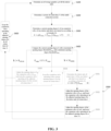
FIG. 2 is a flowchart illustrating main steps of an oil return control method for a multi-connection system of the present disclosure; -
FIG. 3 is a flowchart illustrating detailed steps of the oil return control method for the multi-connection system of the present disclosure; -
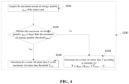
FIG. 4 is a flowchart illustrating detailed steps of step S200 inFIG. 3 ; -
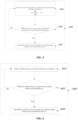
FIG. 5 is a flowchart illustrating detailed steps of an embodiment of step S600 inFIG. 3 ; and -
FIG. 6 is a flowchart illustrating detailed steps of another embodiment of step S600 inFIG. 3 . - Preferred embodiments of the present disclosure will be described below with reference to the accompanying drawings. It should be understood by those skilled in the art that these embodiments are only used to explain the technical principle of the present disclosure, and are not intended to limit the scope of protection of the present disclosure.
- In the description of the present application, a "controller" may include hardware, software, or a combination thereof. A module may include hardware circuits, various suitable sensors, communication ports and memories, and may also include software parts, such as program codes, or a combination of software and hardware.
- In order to facilitate understanding, in the following, a typical structure of a multi-connection system will be first briefly introduced with reference to
FIG. 1 . It should be noted that the dotted line "- - - " inFIG. 1 represents liquid pipes, and the solid line "-" inFIG. 1 represents gas pipes. - Referring to
FIG. 1 , a multi-connection system includes an outdoor unit and n indoor units. Each of the indoor units is connected to the outdoor unit through a gas pipe and a liquid pipe to form a refrigerant circulation system, and each of the indoor units further includes an expansion valve VE. The expansion valve VE is arranged on the liquid pipe between the outdoor unit and the corresponding indoor unit, and is configured to adjust the amount of refrigerant flowing through the indoor unit. When the refrigerant circulates between the outdoor unit and individual indoor units of the multi-connection system, the lubricating oil also circulates with the refrigerant in the system so as to lubricate and cool inner components of a compressor. - When some of the indoor units of the multi-connection system are turned on and working, some other indoor units are in a shutdown or standby state. Therefore, in order to improve readability, the indoor units in the shutdown or standby state are collectively referred to as indoor units that are not turned on herein. In order to prevent the problem of insufficient lubricating oil in the compressor caused by the accumulation of lubricating oil in the indoor units that are not turned on, generally, an opening degree of the expansion valves VE of the indoor units that are not turned on is adjusted to a fixed value within a preset period of time, so that the lubricating oil accumulated in the indoor units that are not turned on flows back into the compressor with the refrigerant, which is called an oil return control process of the multi-connection system.
- However, due to the difference in the actual working conditions of various indoor units that are not turned on, after the oil return control process of the system is completed, a large amount of lubricating oil is still accumulated in some indoor units, causing the compressor to still have the problem of insufficient lubricating oil, and the lubricating oil in some other indoor units has completely flowed back into the compressor before the oil return control process is completed, but the expansion valves VE thereof still maintain a fixed opening degree. When the opening degree of the expansion valves VE is too large, a large amount of refrigerant in the system continues to flow in these indoor units, which will not only cause the liquid hammer phenomenon in the compressor, but also will cause the problems of insufficient amount of the refrigerant in the normally turned-on indoor units and poor heat exchange performance of the system.
- For this reason, the present disclosure provides an oil return control method for a multi-connection system, which can precisely control the opening degree of the expansion valve of each indoor unit that is not turned on and the oil return time thereof, so that at the same time of providing sufficient lubricating oil to the compressor, it can also be ensured that there is sufficient amount of refrigerant in the normally turned-on indoor units, thus giving considerations to both the oil return effect and the heat exchange performance of the system.
- In order to facilitate understanding the oil return control method, a main step flow of the oil return control method for the multi-connection system of the present disclosure will be described hereinafter with reference to
FIG. 2 . - Referring to
FIG. 2 , the main step flow of the oil return control method of the present disclosure includes: - Step S100: determining an oil storage quantity q of all the indoor units;
- Step S200: determining a system oil return time T of the multi-connection system;
- Step S300: determining a current opening degree k of an expansion valve of one indoor unit that is not turned on according to the oil storage quantity q and the system oil return time T;
- Step S400: comparing the current opening degree k with a maximum opening degree threshold ksmax and a minimum opening degree threshold ksmin; and
- Step S500: selectively adjusting the opening degree of the expansion valve according to a comparison result, and keeping the expansion valve operating at the adjusted opening degree for the system oil return time T.
- It should be noted that the expansion valve of the turned-on indoor unit is always in an open state before the oil is returned. In order to ensure the heat exchange effect of the multi-connection system, the opening degrees of the expansion valves of all the turned-on indoor units are normally adjusted according to a control logic before the oil return.
- Further, in order to better understand the oil return control method of the present disclosure, a control flow of the detailed steps of the oil return control method of the present disclosure will described in detail below with reference to
FIG. 3 . - Referring to
FIG. 3 , a detailed step flow of the oil return control method of the present disclosure includes the following steps. - Step S100: determining an oil storage quantity q of all the indoor units.
- Specifically, in step S 100, the oil storage quantity q of the indoor units is determined according to formula (1).

- It should be noted that P represents the capacity horsepower of the indoor unit. This value is a performance parameter of the indoor unit, which has been clearly set at the factory and can be acquired directly when needed, without additional calculation. tsp represents the shutdown time of the indoor unit. The shutdown time tsp of each indoor unit is stored in a controller of the multi-connection system, and can be read directly when needed. Pd and Ps represent the system high pressure and system low pressure of the multi-connection system respectively. These two specific values can be collected by two pressure sensors installed on the outdoor unit, and then transmitted to the controller in a wired or wireless manner for storage. Also, they can be read directly when needed.
- Ro represents the oil storage coefficient of the indoor unit, and this value depends on an ambient temperature Tai of the indoor unit, a saturation temperature Tpd corresponding to the system high pressure and a saturation temperature Tps corresponding to the system low pressure under different working conditions of the system. Table 1 shows the oil storage coefficient Ro obtained under different working conditions of the indoor unit through experimental verification, and an appropriate value can be chosen from Table 1 according to the actual working conditions of the indoor unit during calculation.
Table 1 cooling heating Tai - Tps (°C) Ro Tai - Tpd (°C) Ro >=30 0.5 >=30 0.7 [25,30) 0.7 [25,30) 0.9 [20,25) 1.0 [20,25) 1.1 [15,20) 1.2 [15,20) 1.5 [10,15) 1.4 [10,15) 1.7 <=10 1.8 <=10 2.0 - Step S200: determining a system oil return time T of the multi-connection system.
- Referring to the detailed step flow chart of step S200 in
FIG. 4 , step S200 specifically includes:
Step S201: acquiring the maximum oil storage quantity qmax of the indoor unit. - The controller of the multi-connection system calculates and stores the oil storage quantity q of each indoor unit according to the aforementioned formula (1). The oil storage quantity q of the indoor unit varies according to the different working condition of the indoor unit. In step S201, the controller traverses all the oil storage quantities q of the indoor unit that have been stored, finds out the maximum oil storage quantity qmax therefrom and reads it directly.
- Step S202: judging whether the maximum oil storage quantity qmax is larger than the maximum oil storage quantity threshold qsmax; if yes, the process proceeds to step S203; otherwise, the process proceeds to step S204.
- Step S203: determining the system oil return time T as the maximum oil return time threshold Tsmax.
- Step S204: determining the system oil return time T according to formula (2):

- It should be noted that the values of the maximum oil storage quantity threshold qsmax and the maximum oil return time threshold Tsmax depend on various performance parameters of the indoor unit, and they can be set by those skilled in the art according to the specific performance parameters of the indoor unit.
- After the oil storage quantity q of the indoor unit and the system oil return time T are determined, with continued reference to
FIG. 2 , the oil return control method proceeds to step S300. - Step S300: determining the current opening degree k of the expansion valve of the indoor unit that is not turned on using the formula (3) according to the oil storage quantity q and the system oil return time T:

- Step S400: comparing the current opening degree k with the maximum opening degree threshold ksmax and a minimum opening degree threshold ksmin.
- Step S500: selectively adjusting the opening degree of the expansion valve according to a comparison result, and keeping the expansion valve operating at the adjusted opening degree for the system oil return time T.
- In detail, step S500 specifically includes:
proceeding to step S501 if k<ksmin, and determining the indoor unit oil return time t of the indoor unit according to formula (4):
- Step S502: adjusting the opening degree of the expansion valve to ksmin, and keeping the expansion valve operating at the adjusted opening degree for the indoor unit oil return time t.
- Step S503: adjusting the opening degree of the expansion valve to zero, and keeping the expansion valve operating at the adjusted opening degree for a time T-t; then the process returns to the step of determining q.
- If ksmin ≤ k ≤ ksmax, the process proceeds to step S504 of keeping the expansion valve operating at the current opening degree k for the system oil return time T, and then the process returns to the step of determining q.
- If k>ksmax, then the process proceeds to step S505 of adjusting the opening degree of the expansion valve to ksmax and keeping the expansion valve operating at the adjusted opening degree for the system oil return time T, and then the process returns to the step of determining q.
- Further, referring to
FIG. 3 , in order to enable the oil return control method to run periodically, before returning to the step of determining q, the oil return control method further includes:
Step S600: keeping the expansion valve operating at the adjusted opening degree for an oil return interval time Ti. - In detail, the present disclosure will provide two methods of judging whether the expansion valve has operated at the adjusted opening degree for the oil return interval time Ti, and the two methods will be described in detail below with reference to
FIGS. 5 and 6 . It should be noted that in order to improve readability, the following two methods are distinguished by different step labels. Specifically, steps of the first method are denoted by a label S600, and steps of the second method are denoted by a label S600'. - Referring to
FIG. 5 , step S600 of the first method specifically includes: - Step S601: determining a total oil storage quantity Q of the multi-connection system according to formula (5):

- Step S602: judging whether the total oil storage quantity Q is larger than a maximum total oil storage quantity threshold Qsmax; if yes, the process proceeds to step S603; otherwise, the process returns to step S601.
- Step S603: meaning that the expansion valve has operated at the adjusted opening degree for the oil return interval time Ti.
- Referring to
FIG. 6 , step S600' of the second method specifically includes: - Step S601': acquiring a shutdown time tsp of the indoor unit;
- Step S602': judging whether the shutdown time tsp is larger than a maximum shutdown time threshold tspmax; if yes, the process proceeds to step S603'; otherwise, the process returns to step S601'.
- Step S603': meaning that the expansion valve has operated at the adjusted opening degree for the oil return interval time Ti.
- It can be understood that the method for judging whether the expansion valve has operated at the adjusted opening degree for the oil return interval time Ti is not limited to the above two methods, and those skilled in the art can also use other conventional means to judge.
- In addition, the present disclosure also provides a multi-connection air conditioning system including a controller, and the controller is configured to be capable of executing the above refrigerant flow control method. It should be noted that the basic functional components constituting the multi-connection air conditioning system and the working principle are basically the same as those in the prior art, and can be realized by those skilled in the art completely based on the prior art, so a repeated description thereof will not be given herein.
- Hitherto, the technical solutions of the present disclosure have been described in connection with the preferred embodiments shown in the accompanying drawings, but it is easily understood by those skilled in the art that the scope of protection of the present disclosure is obviously not limited to these specific embodiments. Without departing from the principles of the present disclosure, those skilled in the art can make equivalent changes or replacements to relevant technical features, and all the technical solutions after these changes or replacements will fall within the scope of protection of the present disclosure.
Claims (10)
- An oil return control method for a multi-connection system, the multi-connection system comprising a plurality of indoor units, at least one of which is not turned on, wherein the oil return control method comprises:determining an oil storage quantity q of all the indoor units;determining a system oil return time T of the multi-connection system;determining a current opening degree k of an expansion valve of one indoor unit that is not turned on according to the oil storage quantity q and the system oil return time T;comparing the current opening degree k with a maximum opening degree threshold ksmax and a minimum opening degree threshold ksmin; andselectively adjusting the opening degree of the expansion valve of the one indoor unit that is not turned on according to a comparison result, and keeping the expansion valve operating at the adjusted opening degree for the system oil return time T.
- The oil return control method according to claim 1, wherein the step of "determining a current opening degree k of an expansion valve of the one indoor unit that is not turned on according to the oil storage quantity q and the system oil return time T" specifically comprises calculating the current opening degree k using the following formula:

- The oil return control method according to claim 2, wherein the step of "selectively adjusting the opening degree of the expansion valve of the one indoor unit that is not turned on according to a comparison result, and keeping the expansion valve operating at the adjusted opening degree for the system oil return time T" specifically comprises:determining an indoor unit oil return time t of the one indoor unit that is not turned on according to the following formula if k<ksmin:
 adjusting the opening degree of the expansion valve of the one indoor unit that is not turned on to ksmin, and keeping the expansion valve operating at the adjusted opening degree for the time t; andadjusting the opening degree of the expansion valve to zero, keeping the expansion valve operating at the adjusted opening degree for a time T-t, and then returning to the step of determining q.
 - The oil return control method according to claim 2, wherein the step of "selectively adjusting the opening degree of the expansion valve of the one indoor unit that is not turned on according to a comparison result, and keeping the expansion valve operating at the adjusted opening degree for the system oil return time T" specifically comprises:
keeping the expansion valve operating at the current opening degree k for the system oil return time T if ksmin≤k≤ksmax, and then returning to the step of determining q. - The oil return control method according to claim 2, wherein the step of "selectively adjusting the opening degree of the expansion valve of the one indoor unit that is not turned on according to a comparison result, and keeping the expansion valve operating at the adjusted opening degree for the system oil return time T" specifically comprises:
adjusting the opening degree of the expansion valve to ksmax if k>ksmax, keeping the expansion valve operating at the adjusted opening degree for the system oil return time T, and then returning to the step of determining q. - The oil return control method according to any one of claims 3 to 5, wherein before returning to the step of determining q, the expansion valve is kept operating at the adjusted opening degree for an oil return interval time Ti.
- The oil return control method according to claim 6, wherein the oil return interval time Ti is determined through the following steps:determining a total oil storage quantity Q of the multi-connection system according to the following formula:
 judging whether the total oil storage quantity Q is larger than a maximum total oil storage quantity threshold Qsmax;if yes, it means that the expansion valve has operated at the adjusted opening degree for the oil return interval time Ti;where n represents the number of the indoor units, and qi represents the oil storage quantity of the ith indoor unit.
 - The oil return control method according to claim 6, wherein the oil return interval time Ti is determined through the following steps:acquiring a shutdown time tsp of the one indoor unit that is not turned on; andjudging whether the shutdown time tsp is larger than or equal to a maximum shutdown time threshold tspmax;if yes, it means that the expansion valve has operated at the adjusted opening degree for the oil return interval time Ti.
- The oil return control method according to any one of claims 1 to 8, wherein the oil storage quantity q of the indoor unit is determined according to the following formula in the oil return control method:

- The oil return control method according to claim 9, wherein the step of "determining a system oil return time T of the multi-connection system" comprises:acquiring a maximum oil storage quantity qmax of the indoor unit;judging whether the maximum oil storage quantity qmax is larger than the maximum oil storage quantity threshold qsmax;if yes, determining the system oil return time T as the maximum oil return time threshold Tsmax; otherwise, determining the system oil return time T according to the following formula:

Applications Claiming Priority (2)
| Application Number | Priority Date | Filing Date | Title |
|---|---|---|---|
| CN202010449608.8A CN113719963B (en) | 2020-05-25 | 2020-05-25 | Oil return control method of multi-split air conditioning system |
| PCT/CN2021/075909 WO2021223481A1 (en) | 2020-05-25 | 2021-02-08 | Oil return control method for multi-split system |
Publications (3)
| Publication Number | Publication Date |
|---|---|
| EP4160102A1 true EP4160102A1 (en) | 2023-04-05 |
| EP4160102A4 EP4160102A4 (en) | 2023-12-06 |
| EP4160102B1 EP4160102B1 (en) | 2025-01-08 |
Family
ID=78467790
Family Applications (1)
| Application Number | Title | Priority Date | Filing Date |
|---|---|---|---|
| EP21800140.2A Active EP4160102B1 (en) | 2020-05-25 | 2021-02-08 | Oil return control method for multi-split system |
Country Status (3)
| Country | Link |
|---|---|
| EP (1) | EP4160102B1 (en) |
| CN (1) | CN113719963B (en) |
| WO (1) | WO2021223481A1 (en) |
Families Citing this family (3)
| Publication number | Priority date | Publication date | Assignee | Title |
|---|---|---|---|---|
| CN114135973B (en) * | 2021-11-15 | 2023-02-03 | 珠海格力电器股份有限公司 | Multi-split air conditioner control method and device and multi-split air conditioner |
| CN115789995B (en) * | 2022-10-18 | 2025-06-20 | 青岛海尔空调电子有限公司 | Control method and device for compressor oil return, compressor system |
| IT202200022080A1 (en) * | 2022-10-26 | 2024-04-26 | Ariston Spa | Heat pump with extended modulation of the expansion device |
Family Cites Families (14)
| Publication number | Priority date | Publication date | Assignee | Title |
|---|---|---|---|---|
| JPH102626A (en) * | 1996-06-12 | 1998-01-06 | Mitsubishi Heavy Ind Ltd | Air conditioner |
| CN100520208C (en) * | 2006-07-12 | 2009-07-29 | 松下电器产业株式会社 | Multi-room type air-conditioning device |
| JP4877052B2 (en) * | 2006-07-12 | 2012-02-15 | パナソニック株式会社 | Multi-room air conditioner |
| JP5484930B2 (en) * | 2010-01-25 | 2014-05-07 | 三菱重工業株式会社 | Air conditioner |
| JP5798830B2 (en) * | 2011-07-29 | 2015-10-21 | 三菱重工業株式会社 | Supercritical cycle heat pump |
| JP6790115B2 (en) * | 2016-11-25 | 2020-11-25 | 三菱電機株式会社 | Refrigeration cycle equipment |
| CN106839330B (en) * | 2017-03-03 | 2020-01-07 | 广东美的暖通设备有限公司 | Oil balance control method and oil balance control device, multi-line air conditioning system |
| CN108224850A (en) * | 2017-12-29 | 2018-06-29 | 广东美的制冷设备有限公司 | Method for controlling oil return, device, air conditioner and computer readable storage medium |
| CN109357440B (en) * | 2018-10-26 | 2019-11-05 | 宁波奥克斯电气股份有限公司 | A kind of multi-connected machine heating method for controlling oil return and multi-gang air-conditioner device |
| CN109631248B (en) * | 2018-11-16 | 2021-05-25 | 青岛海尔空调电子有限公司 | Multi-split air conditioner refrigeration oil return noise reduction control method and system |
| CN109612021B (en) * | 2018-11-28 | 2021-04-20 | 宁波奥克斯电气股份有限公司 | Multi-connected air conditioning system abnormal sound control method and multi-connected air conditioning system |
| CN110296547B (en) * | 2019-07-04 | 2020-04-21 | 宁波奥克斯电气股份有限公司 | A kind of multi-line oil return control method, system and air conditioner |
| CN110542255B (en) * | 2019-09-06 | 2020-07-07 | 珠海格力电器股份有限公司 | Compressor oil return method, refrigeration system and air conditioner |
| CN111141074B (en) * | 2020-01-06 | 2022-06-24 | 宁波奥克斯电气股份有限公司 | Air conditioner control method and device, air conditioner and storage medium |
-
2020
- 2020-05-25 CN CN202010449608.8A patent/CN113719963B/en active Active
-
2021
- 2021-02-08 EP EP21800140.2A patent/EP4160102B1/en active Active
- 2021-02-08 WO PCT/CN2021/075909 patent/WO2021223481A1/en not_active Ceased
Also Published As
| Publication number | Publication date |
|---|---|
| WO2021223481A1 (en) | 2021-11-11 |
| EP4160102B1 (en) | 2025-01-08 |
| CN113719963A (en) | 2021-11-30 |
| EP4160102A4 (en) | 2023-12-06 |
| CN113719963B (en) | 2022-12-27 |
Similar Documents
| Publication | Publication Date | Title |
|---|---|---|
| EP3748266B1 (en) | Vrv oil return control method and system | |
| EP4160102B1 (en) | Oil return control method for multi-split system | |
| CN107218741B (en) | Oil return control method for multi-split air conditioning system | |
| CN116428762B (en) | A refrigerant bias flow control method, device and multi-connected system | |
| JP5201183B2 (en) | Air conditioner and method of operating refrigerator | |
| KR102114174B1 (en) | Heat pump based automatic control geothermal system and the control method thereof | |
| CN108592297A (en) | Air conditioner defrosting control method | |
| CN114427741A (en) | Air conditioner cold water system control method and device, electronic equipment and storage medium | |
| JP2010025466A (en) | Heat source system | |
| CN117053406A (en) | Heat pump multi-split air conditioner with natural fluoride hot water and control method thereof | |
| CN103791658B (en) | Oil quantity regulating and controlling method for multi-connected air conditioning unit | |
| CN104613667A (en) | Combined air-conditioning system as well as control method thereof | |
| JP2016121861A (en) | Snow and ice air conditioning system and its control device | |
| EP3862661B1 (en) | Air conditioning apparatus and method for controlling an air conditioning apparatus | |
| JP4513545B2 (en) | Refrigeration unit control system and cooling supply system | |
| CN105546890A (en) | Air conditioner energy output regulating method and air conditioner | |
| JP5913066B2 (en) | Heat source system | |
| CN120760364A (en) | Refrigerant replenishment control method, device, refrigeration equipment and computer-readable storage medium | |
| CN108692425B (en) | Air conditioner defrosting control method | |
| KR20240113211A (en) | Superheating control method of heat pump system | |
| CN111854206B (en) | Refrigerator equipment, refrigerating system and control method of refrigerating system | |
| CN108800451A (en) | air conditioner defrosting control method | |
| CN115218309A (en) | Gas heat pump water chiller-heater unit, control method and air conditioner | |
| CN114909724A (en) | Method and device for cooling outdoor unit of air conditioner, air conditioner and storage medium | |
| CN113686036B (en) | Cooling system and control method for regulating temperature of cooling equipment |
Legal Events
| Date | Code | Title | Description |
|---|---|---|---|
| STAA | Information on the status of an ep patent application or granted ep patent |
Free format text: STATUS: THE INTERNATIONAL PUBLICATION HAS BEEN MADE |
|
| PUAI | Public reference made under article 153(3) epc to a published international application that has entered the european phase |
Free format text: ORIGINAL CODE: 0009012 |
|
| STAA | Information on the status of an ep patent application or granted ep patent |
Free format text: STATUS: REQUEST FOR EXAMINATION WAS MADE |
|
| 17P | Request for examination filed |
Effective date: 20220330 |
|
| AK | Designated contracting states |
Kind code of ref document: A1 Designated state(s): AL AT BE BG CH CY CZ DE DK EE ES FI FR GB GR HR HU IE IS IT LI LT LU LV MC MK MT NL NO PL PT RO RS SE SI SK SM TR |
|
| DAV | Request for validation of the european patent (deleted) | ||
| DAX | Request for extension of the european patent (deleted) | ||
| A4 | Supplementary search report drawn up and despatched |
Effective date: 20231108 |
|
| RIC1 | Information provided on ipc code assigned before grant |
Ipc: F25B 49/02 20060101ALI20231102BHEP Ipc: F25B 5/02 20060101ALI20231102BHEP Ipc: F25B 31/00 20060101ALI20231102BHEP Ipc: F24F 11/70 20180101ALI20231102BHEP Ipc: F24F 11/64 20180101ALI20231102BHEP Ipc: F24F 11/32 20180101AFI20231102BHEP |
|
| GRAP | Despatch of communication of intention to grant a patent |
Free format text: ORIGINAL CODE: EPIDOSNIGR1 |
|
| GRAJ | Information related to disapproval of communication of intention to grant by the applicant or resumption of examination proceedings by the epo deleted |
Free format text: ORIGINAL CODE: EPIDOSDIGR1 |
|
| GRAP | Despatch of communication of intention to grant a patent |
Free format text: ORIGINAL CODE: EPIDOSNIGR1 |
|
| STAA | Information on the status of an ep patent application or granted ep patent |
Free format text: STATUS: GRANT OF PATENT IS INTENDED |
|
| GRAJ | Information related to disapproval of communication of intention to grant by the applicant or resumption of examination proceedings by the epo deleted |
Free format text: ORIGINAL CODE: EPIDOSDIGR1 |
|
| STAA | Information on the status of an ep patent application or granted ep patent |
Free format text: STATUS: REQUEST FOR EXAMINATION WAS MADE |
|
| GRAP | Despatch of communication of intention to grant a patent |
Free format text: ORIGINAL CODE: EPIDOSNIGR1 |
|
| STAA | Information on the status of an ep patent application or granted ep patent |
Free format text: STATUS: GRANT OF PATENT IS INTENDED |
|
| GRAS | Grant fee paid |
Free format text: ORIGINAL CODE: EPIDOSNIGR3 |
|
| INTG | Intention to grant announced |
Effective date: 20241106 |
|
| GRAA | (expected) grant |
Free format text: ORIGINAL CODE: 0009210 |
|
| STAA | Information on the status of an ep patent application or granted ep patent |
Free format text: STATUS: THE PATENT HAS BEEN GRANTED |
|
| AK | Designated contracting states |
Kind code of ref document: B1 Designated state(s): AL AT BE BG CH CY CZ DE DK EE ES FI FR GB GR HR HU IE IS IT LI LT LU LV MC MK MT NL NO PL PT RO RS SE SI SK SM TR |
|
| REG | Reference to a national code |
Ref country code: GB Ref legal event code: FG4D |
|
| REG | Reference to a national code |
Ref country code: CH Ref legal event code: EP |
|
| REG | Reference to a national code |
Ref country code: DE Ref legal event code: R096 Ref document number: 602021024742 Country of ref document: DE |
|
| REG | Reference to a national code |
Ref country code: IE Ref legal event code: FG4D |
|
| PGFP | Annual fee paid to national office [announced via postgrant information from national office to epo] |
Ref country code: AT Payment date: 20250417 Year of fee payment: 5 |
|
| REG | Reference to a national code |
Ref country code: LT Ref legal event code: MG9D |
|
| REG | Reference to a national code |
Ref country code: NL Ref legal event code: MP Effective date: 20250108 |
|
| REG | Reference to a national code |
Ref country code: AT Ref legal event code: MK05 Ref document number: 1758556 Country of ref document: AT Kind code of ref document: T Effective date: 20250108 |
|
| PG25 | Lapsed in a contracting state [announced via postgrant information from national office to epo] |
Ref country code: NL Free format text: LAPSE BECAUSE OF FAILURE TO SUBMIT A TRANSLATION OF THE DESCRIPTION OR TO PAY THE FEE WITHIN THE PRESCRIBED TIME-LIMIT Effective date: 20250108 |
|
| PG25 | Lapsed in a contracting state [announced via postgrant information from national office to epo] |
Ref country code: RS Free format text: LAPSE BECAUSE OF FAILURE TO SUBMIT A TRANSLATION OF THE DESCRIPTION OR TO PAY THE FEE WITHIN THE PRESCRIBED TIME-LIMIT Effective date: 20250408 |
|
| PG25 | Lapsed in a contracting state [announced via postgrant information from national office to epo] |
Ref country code: FI Free format text: LAPSE BECAUSE OF FAILURE TO SUBMIT A TRANSLATION OF THE DESCRIPTION OR TO PAY THE FEE WITHIN THE PRESCRIBED TIME-LIMIT Effective date: 20250108 |
|
| PG25 | Lapsed in a contracting state [announced via postgrant information from national office to epo] |
Ref country code: PL Free format text: LAPSE BECAUSE OF FAILURE TO SUBMIT A TRANSLATION OF THE DESCRIPTION OR TO PAY THE FEE WITHIN THE PRESCRIBED TIME-LIMIT Effective date: 20250108 |
|
| PG25 | Lapsed in a contracting state [announced via postgrant information from national office to epo] |
Ref country code: ES Free format text: LAPSE BECAUSE OF FAILURE TO SUBMIT A TRANSLATION OF THE DESCRIPTION OR TO PAY THE FEE WITHIN THE PRESCRIBED TIME-LIMIT Effective date: 20250108 |
|
| PG25 | Lapsed in a contracting state [announced via postgrant information from national office to epo] |
Ref country code: NO Free format text: LAPSE BECAUSE OF FAILURE TO SUBMIT A TRANSLATION OF THE DESCRIPTION OR TO PAY THE FEE WITHIN THE PRESCRIBED TIME-LIMIT Effective date: 20250408 Ref country code: IS Free format text: LAPSE BECAUSE OF FAILURE TO SUBMIT A TRANSLATION OF THE DESCRIPTION OR TO PAY THE FEE WITHIN THE PRESCRIBED TIME-LIMIT Effective date: 20250508 |
|
| PG25 | Lapsed in a contracting state [announced via postgrant information from national office to epo] |
Ref country code: HR Free format text: LAPSE BECAUSE OF FAILURE TO SUBMIT A TRANSLATION OF THE DESCRIPTION OR TO PAY THE FEE WITHIN THE PRESCRIBED TIME-LIMIT Effective date: 20250108 |
|
| PG25 | Lapsed in a contracting state [announced via postgrant information from national office to epo] |
Ref country code: PT Free format text: LAPSE BECAUSE OF FAILURE TO SUBMIT A TRANSLATION OF THE DESCRIPTION OR TO PAY THE FEE WITHIN THE PRESCRIBED TIME-LIMIT Effective date: 20250508 Ref country code: LV Free format text: LAPSE BECAUSE OF FAILURE TO SUBMIT A TRANSLATION OF THE DESCRIPTION OR TO PAY THE FEE WITHIN THE PRESCRIBED TIME-LIMIT Effective date: 20250108 |
|
| PG25 | Lapsed in a contracting state [announced via postgrant information from national office to epo] |
Ref country code: BG Free format text: LAPSE BECAUSE OF FAILURE TO SUBMIT A TRANSLATION OF THE DESCRIPTION OR TO PAY THE FEE WITHIN THE PRESCRIBED TIME-LIMIT Effective date: 20250108 Ref country code: GR Free format text: LAPSE BECAUSE OF FAILURE TO SUBMIT A TRANSLATION OF THE DESCRIPTION OR TO PAY THE FEE WITHIN THE PRESCRIBED TIME-LIMIT Effective date: 20250409 |
|
| PG25 | Lapsed in a contracting state [announced via postgrant information from national office to epo] |
Ref country code: AT Free format text: LAPSE BECAUSE OF FAILURE TO SUBMIT A TRANSLATION OF THE DESCRIPTION OR TO PAY THE FEE WITHIN THE PRESCRIBED TIME-LIMIT Effective date: 20250108 |
|
| REG | Reference to a national code |
Ref country code: DE Ref legal event code: R119 Ref document number: 602021024742 Country of ref document: DE |
|
| PG25 | Lapsed in a contracting state [announced via postgrant information from national office to epo] |
Ref country code: SE Free format text: LAPSE BECAUSE OF FAILURE TO SUBMIT A TRANSLATION OF THE DESCRIPTION OR TO PAY THE FEE WITHIN THE PRESCRIBED TIME-LIMIT Effective date: 20250108 |
|
| REG | Reference to a national code |
Ref country code: CH Ref legal event code: PL |
|
| PG25 | Lapsed in a contracting state [announced via postgrant information from national office to epo] |
Ref country code: SM Free format text: LAPSE BECAUSE OF FAILURE TO SUBMIT A TRANSLATION OF THE DESCRIPTION OR TO PAY THE FEE WITHIN THE PRESCRIBED TIME-LIMIT Effective date: 20250108 |
|
| PG25 | Lapsed in a contracting state [announced via postgrant information from national office to epo] |
Ref country code: DK Free format text: LAPSE BECAUSE OF FAILURE TO SUBMIT A TRANSLATION OF THE DESCRIPTION OR TO PAY THE FEE WITHIN THE PRESCRIBED TIME-LIMIT Effective date: 20250108 |
|
| PG25 | Lapsed in a contracting state [announced via postgrant information from national office to epo] |
Ref country code: MC Free format text: LAPSE BECAUSE OF FAILURE TO SUBMIT A TRANSLATION OF THE DESCRIPTION OR TO PAY THE FEE WITHIN THE PRESCRIBED TIME-LIMIT Effective date: 20250108 |
|
| PG25 | Lapsed in a contracting state [announced via postgrant information from national office to epo] |
Ref country code: LU Free format text: LAPSE BECAUSE OF NON-PAYMENT OF DUE FEES Effective date: 20250208 |
|
| PG25 | Lapsed in a contracting state [announced via postgrant information from national office to epo] |
Ref country code: CH Free format text: LAPSE BECAUSE OF NON-PAYMENT OF DUE FEES Effective date: 20250228 |
|
| PG25 | Lapsed in a contracting state [announced via postgrant information from national office to epo] |
Ref country code: EE Free format text: LAPSE BECAUSE OF FAILURE TO SUBMIT A TRANSLATION OF THE DESCRIPTION OR TO PAY THE FEE WITHIN THE PRESCRIBED TIME-LIMIT Effective date: 20250108 Ref country code: CZ Free format text: LAPSE BECAUSE OF FAILURE TO SUBMIT A TRANSLATION OF THE DESCRIPTION OR TO PAY THE FEE WITHIN THE PRESCRIBED TIME-LIMIT Effective date: 20250108 |
|
| PG25 | Lapsed in a contracting state [announced via postgrant information from national office to epo] |
Ref country code: RO Free format text: LAPSE BECAUSE OF FAILURE TO SUBMIT A TRANSLATION OF THE DESCRIPTION OR TO PAY THE FEE WITHIN THE PRESCRIBED TIME-LIMIT Effective date: 20250108 |
|
| PG25 | Lapsed in a contracting state [announced via postgrant information from national office to epo] |
Ref country code: SK Free format text: LAPSE BECAUSE OF FAILURE TO SUBMIT A TRANSLATION OF THE DESCRIPTION OR TO PAY THE FEE WITHIN THE PRESCRIBED TIME-LIMIT Effective date: 20250108 |
|
| PLBE | No opposition filed within time limit |
Free format text: ORIGINAL CODE: 0009261 |
|
| STAA | Information on the status of an ep patent application or granted ep patent |
Free format text: STATUS: NO OPPOSITION FILED WITHIN TIME LIMIT |
|
| REG | Reference to a national code |
Ref country code: BE Ref legal event code: MM Effective date: 20250228 |
|
| 26N | No opposition filed |
Effective date: 20251009 |
|
| PG25 | Lapsed in a contracting state [announced via postgrant information from national office to epo] |
Ref country code: DE Free format text: LAPSE BECAUSE OF NON-PAYMENT OF DUE FEES Effective date: 20250902 |
|
| PG25 | Lapsed in a contracting state [announced via postgrant information from national office to epo] |
Ref country code: IT Free format text: LAPSE BECAUSE OF NON-PAYMENT OF DUE FEES Effective date: 20250208 |
|
| PG25 | Lapsed in a contracting state [announced via postgrant information from national office to epo] |
Ref country code: BE Free format text: LAPSE BECAUSE OF NON-PAYMENT OF DUE FEES Effective date: 20250228 |
|
| PG25 | Lapsed in a contracting state [announced via postgrant information from national office to epo] |
Ref country code: IE Free format text: LAPSE BECAUSE OF NON-PAYMENT OF DUE FEES Effective date: 20250208 |
|
| PGFP | Annual fee paid to national office [announced via postgrant information from national office to epo] |
Ref country code: GB Payment date: 20260220 Year of fee payment: 6 |
|
| PGFP | Annual fee paid to national office [announced via postgrant information from national office to epo] |
Ref country code: FR Payment date: 20260219 Year of fee payment: 6 |
|
| PG25 | Lapsed in a contracting state [announced via postgrant information from national office to epo] |
Ref country code: CY Free format text: LAPSE BECAUSE OF FAILURE TO SUBMIT A TRANSLATION OF THE DESCRIPTION OR TO PAY THE FEE WITHIN THE PRESCRIBED TIME-LIMIT Effective date: 20250108 |
|
| PG25 | Lapsed in a contracting state [announced via postgrant information from national office to epo] |
Ref country code: TR Free format text: LAPSE BECAUSE OF FAILURE TO SUBMIT A TRANSLATION OF THE DESCRIPTION OR TO PAY THE FEE WITHIN THE PRESCRIBED TIME-LIMIT Effective date: 20250108 |
|
| PG25 | Lapsed in a contracting state [announced via postgrant information from national office to epo] |
Ref country code: LT Free format text: LAPSE BECAUSE OF FAILURE TO SUBMIT A TRANSLATION OF THE DESCRIPTION OR TO PAY THE FEE WITHIN THE PRESCRIBED TIME-LIMIT Effective date: 20250108 |