EP4160036B1 - Ball-hinged transmission shaft with straight shaft - Google Patents
Ball-hinged transmission shaft with straight shaft Download PDFInfo
- Publication number
- EP4160036B1 EP4160036B1 EP21857494.5A EP21857494A EP4160036B1 EP 4160036 B1 EP4160036 B1 EP 4160036B1 EP 21857494 A EP21857494 A EP 21857494A EP 4160036 B1 EP4160036 B1 EP 4160036B1
- Authority
- EP
- European Patent Office
- Prior art keywords
- ball
- shaft
- rolling element
- straight
- socket
- Prior art date
- Legal status (The legal status is an assumption and is not a legal conclusion. Google has not performed a legal analysis and makes no representation as to the accuracy of the status listed.)
- Active
Links
Images




Classifications
-
- F—MECHANICAL ENGINEERING; LIGHTING; HEATING; WEAPONS; BLASTING
- F16—ENGINEERING ELEMENTS AND UNITS; GENERAL MEASURES FOR PRODUCING AND MAINTAINING EFFECTIVE FUNCTIONING OF MACHINES OR INSTALLATIONS; THERMAL INSULATION IN GENERAL
- F16D—COUPLINGS FOR TRANSMITTING ROTATION; CLUTCHES; BRAKES
- F16D3/00—Yielding couplings, i.e. with means permitting movement between the connected parts during the drive
- F16D3/16—Universal joints in which flexibility is produced by means of pivots or sliding or rolling connecting parts
- F16D3/26—Hooke's joints or other joints with an equivalent intermediate member to which each coupling part is pivotally or slidably connected
- F16D3/44—Hooke's joints or other joints with an equivalent intermediate member to which each coupling part is pivotally or slidably connected the intermediate member being connected to the coupling parts by ridges, pins, balls, or the like guided in grooves or between cogs
-
- F—MECHANICAL ENGINEERING; LIGHTING; HEATING; WEAPONS; BLASTING
- F16—ENGINEERING ELEMENTS AND UNITS; GENERAL MEASURES FOR PRODUCING AND MAINTAINING EFFECTIVE FUNCTIONING OF MACHINES OR INSTALLATIONS; THERMAL INSULATION IN GENERAL
- F16D—COUPLINGS FOR TRANSMITTING ROTATION; CLUTCHES; BRAKES
- F16D3/00—Yielding couplings, i.e. with means permitting movement between the connected parts during the drive
- F16D3/16—Universal joints in which flexibility is produced by means of pivots or sliding or rolling connecting parts
- F16D3/26—Hooke's joints or other joints with an equivalent intermediate member to which each coupling part is pivotally or slidably connected
Definitions
- the present invention relates to the field of mechanical equipment, in particular, to a ball-hinged transmission shaft with a straight shaft.
- the present invention is deemed as a further optimization and improvement on the Chinese Patent Application No. CN 201710956327.X (filed on October 16, 2017 , with publication No. CN 107605980 A ) and the Chinese Patent Application No. CN 201721322884.8 (filed on October 16, 2017 , with publication No. CN 207333486 U ).
- the large contact stress between a straight shaft and a transmission hole during transmission is distributed unreasonably and is mainly concentrated at the mouth of the transmission hole, resulting in the mouth of the transmission hole being abraded quickly to affect the service life of the product.
- the present invention is intended to overcome the above shortages to prolong the service life of the product.
- the main objective of the present invention is to provide a ball-hinged transmission shaft with a straight shaft to solve the problem that the large contact stress between a straight shaft and a transmission hole is distributed unreasonably to abrade the mouth of the transmission hole quickly to affect the service life of the product in the prior art.
- a ball-hinged transmission shaft with a straight shaft includes a socket, a ball, and a straight shaft.
- An outer spherical surface of the ball is positioned and limited in an inner positioning spherical surface of the socket to form a sliding fit pair.
- a transmission hole is formed in the ball.
- the straight shaft is hinged into a bearing hole of the socket through a bearing.
- a rolling element is further coaxially provided on the straight shaft.
- the rolling element is a rotator with an axis of the straight shaft as the center of rotation.
- the rolling element is externally connected to the bearing.
- the mouth-shaped surface is further respectively provided at two ends of the transmission hole of the ball.
- the mouth-shaped surface is a curved surface matching the shape of the rolling element.
- the rolling element is fit and provided in the mouth-shaped surface at the two ends of the transmission hole of the ball.
- the ball is restricted by the inner positioning spherical surface of the socket, the straight shaft, and the rolling element at the same time.
- the rolling element may rotate around the axis of the straight shaft, while rolling along the mouth-shaped surface of the transmission hole, thereby transmitting a power and a rotational speed between the ball and the socket in a state where a certain included angle is formed between the axis of the ball handle and the axis of the socket.
- the outer surface of the rolling element matching the mouth-shaped surface is a tapered surface, and a contact generatrix between the tapered surface and the mouth-shaped surface is a straight line.
- an extended line of the contact generatrix passes through the center of the inner spherical surface of the socket.
- an outer surface of the rolling element matching the mouth-shaped surface is a revolution curved surface
- a contact generatrix between the revolution curved surface and the mouth-shaped surface is a curved line.
- contact generatrix is an arc, a hyperbolic curve, or an involute.
- bearing is a tapered roller bearing (TRB).
- the bearing is a TRB, and the rolling element and an inner ring of the bearing are of an integral structure.
- the socket is of an integral or split structure.
- the transmission shaft includes a spline shaft and a spline housing, and the transmission shaft is stretched and retracted through cooperation between the spline shaft and the spline housing.
- two sockets are connected oppositely and symmetrically and integrated for use.
- Q ball
- Q-1 transmission hole
- Q-2 outer spherical surface of ball
- Q-3 ball handle
- Q-4 mouth-shaped surface
- S straight shaft
- W socket
- W-1 inner positioning spherical surface
- W-2 bearing hole
- Z bearing
- M rolling element
- M-1 contact generatrix
- G dust cover
- C transmission shaft
- a ball-hinged transmission shaft with a straight shaft includes socket W, ball Q, and straight shaft S.
- Outer spherical surface Q-2 of the ball is positioned and limited in inner positioning spherical surface W-1 of the socket to form a sliding fit pair.
- Transmission hole Q-1 is formed in the ball.
- Mouth-shaped surface Q-4 is further respectively provided at two ends of the transmission hole, as shown in FIG. 1 .
- Rolling element M is further coaxially provided on the straight shaft.
- the rolling element is a tapered element with an axis of the straight shaft as the center of rotation.
- the straight shaft passes through the transmission hole of the ball with two ends each hinged into bearing hole W-2 of the socket through bearing Z and limiting an axial position of the rolling element.
- An outer tapered surface of the rolling element matches the mouth-shaped surface at the two ends of the transmission hole of the ball.
- Contact generatrix M-1 between the rolling element and the mouth-shaped surface is a straight line with an extended line passing through the center of
- the ball Q is restricted by the inner positioning spherical surface W-1 of the socket, the straight shaft S, and the rolling element M at the same time.
- Ball handle Q-3 of the ball Q may swing around the center of the inner positioning spherical surface of the socket.
- the rolling element may rotate around the axis of the straight shaft, while rolling along the mouth-shaped surface of the transmission hole, thereby transmitting a power or a rotational speed between the ball and the socket in a state where a certain included angle is formed between an axis of the ball handle and an axis of the socket, as shown in FIG. 15 .
- the rolling element is the tapered element, and the extended line of the contact generatrix between the rolling element and the mouth-shaped surface passes through the center of the ball.
- the rolling element can keep rolling on the mouth-shaped surface, which reduces or prevents sliding friction between the rolling element and the mouth-shaped contact surface, reduces abrasion and heating of the mouth-shaped surface and the rolling element, and prolongs the service life of the product.
- Embodiment 2 is a variation of Embodiment 1 with the following main differences:
- the rolling element has a different shape.
- the outer surface of the rolling element matching the mouth-shaped surface of the transmission hole is a revolution curved surface
- a contact generatrix between the revolution curved surface and the mouth-shaped surface of the transmission hole is a curved line.
- the curved line may be an arc, a hyperbolic curve, an involute, and so on as required. In this way, the effective contact area between the rolling element and the mouth-shaped surface of the transmission hole of the ball in power transmission can be increased, the contact stress can be reduced, and the service life of the product can be prolonged.
- the socket may be of an integral structure or a split structure.
- FIG. 5 , FIG. 9, and FIG. 10 show the integral structure
- FIG. 6 , FIG. 11, and FIG. 12 show the split structure.
- Other descriptions are similar to the above and will not be repeated herein.
- the bearing may be a TRB.
- the rolling element may be integrated with an inner ring of the TRB to use fewer components and achieve a simpler structure, a better quality and a lower cost. Other descriptions are similar to the above and will not be repeated herein.
- FIG. 13 is a schematic view illustrating that two fit pairs of ball and socket are paired for use.
- Two sockets are respectively arranged at two ends of a transmission shaft C assembly.
- the transmission shaft may be stretched and retracted in the length direction through cooperation between a spline shaft and a spline housing to adapt to a mounting distance of the transmission shaft.
- Dust cover G is sleeved on the spline shaft and the spline housing and configured to prevent dust and seal a lubricant.
- the extension or retraction of the transmission shaft may also be realized in other manners and is not limited to the above manner. To make the transmission more stable, the straight shaft must keep the same mounting direction. Other descriptions are similar to the above and will not be repeated herein.
- FIG. 14 is a schematic view illustrating that two back-to-back sockets are integrated for use. Two balls are respectively at two ends of a transmission shaft assembly and are docked with a transmission system through ball handles. Other descriptions are similar to the above and will not be repeated herein.
- orientations or position relationships indicated by terms such as “front end”, “rear end”, “left”, “right”, “upper”, “lower”, and “horizontal” are shown in the drawings. These terms are merely used to facilitate and simplify the description, rather than to indicate or imply that the mentioned apparatus or elements must have a specific orientation and must be established and operated in a specific orientation. Therefore, these terms should not be understood as a limitation of the present disclosure.
- connection may be a fixed, removable, or integral connection; a mechanical or an electrical connection; may be a direct or an indirect connection by using an intermediate medium; or intercommunication between two components.
- connection may be a fixed, removable, or integral connection; a mechanical or an electrical connection; may be a direct or an indirect connection by using an intermediate medium; or intercommunication between two components.
Landscapes
- Engineering & Computer Science (AREA)
- General Engineering & Computer Science (AREA)
- Mechanical Engineering (AREA)
- Pivots And Pivotal Connections (AREA)
- Rolling Contact Bearings (AREA)
Description
- The present invention relates to the field of mechanical equipment, in particular, to a ball-hinged transmission shaft with a straight shaft.
- The present invention is deemed as a further optimization and improvement on the Chinese Patent Application No.
CN 201710956327.X (filed on October 16, 2017 CN 107605980 A ) and the Chinese Patent Application No.CN 201721322884.8 (filed on October 16, 2017 CN 207333486 U ). According to the above-mentioned patented technologies, the large contact stress between a straight shaft and a transmission hole during transmission is distributed unreasonably and is mainly concentrated at the mouth of the transmission hole, resulting in the mouth of the transmission hole being abraded quickly to affect the service life of the product. Further, when the cylindrical straight shaft rolls on the surface of the transmission hole, the contact generatrix of the cylindrical straight shaft slides largely relative to the contact surface of the transmission hole, which accelerates abrasion of the contact surface to shorten the service life of the product. The present invention is intended to overcome the above shortages to prolong the service life of the product. - Other ball-hinged transmissions are disclosed in the documents:
CN 106 969 058 A ,GB 458 006 A GB 2 139 319 A - The main objective of the present invention is to provide a ball-hinged transmission shaft with a straight shaft to solve the problem that the large contact stress between a straight shaft and a transmission hole is distributed unreasonably to abrade the mouth of the transmission hole quickly to affect the service life of the product in the prior art.
- To achieve the above objective, the present invention adopts the following technical solutions:
A ball-hinged transmission shaft with a straight shaft includes a socket, a ball, and a straight shaft. An outer spherical surface of the ball is positioned and limited in an inner positioning spherical surface of the socket to form a sliding fit pair. A transmission hole is formed in the ball. After passing through the transmission hole of the ball, the straight shaft is hinged into a bearing hole of the socket through a bearing. A rolling element is further coaxially provided on the straight shaft. The rolling element is a rotator with an axis of the straight shaft as the center of rotation. The rolling element is externally connected to the bearing. The mouth-shaped surface is further respectively provided at two ends of the transmission hole of the ball. The mouth-shaped surface is a curved surface matching the shape of the rolling element. The rolling element is fit and provided in the mouth-shaped surface at the two ends of the transmission hole of the ball. The ball is restricted by the inner positioning spherical surface of the socket, the straight shaft, and the rolling element at the same time. When a ball handle of the ball swings around the center of the inner positioning spherical surface of the socket, the rolling element may rotate around the axis of the straight shaft, while rolling along the mouth-shaped surface of the transmission hole, thereby transmitting a power and a rotational speed between the ball and the socket in a state where a certain included angle is formed between the axis of the ball handle and the axis of the socket. - Further, the outer surface of the rolling element matching the mouth-shaped surface is a tapered surface, and a contact generatrix between the tapered surface and the mouth-shaped surface is a straight line.
- Further, an extended line of the contact generatrix passes through the center of the inner spherical surface of the socket.
- Further, an outer surface of the rolling element matching the mouth-shaped surface is a revolution curved surface, and a contact generatrix between the revolution curved surface and the mouth-shaped surface is a curved line.
- Further, the contact generatrix is an arc, a hyperbolic curve, or an involute.
- Further, the bearing is a tapered roller bearing (TRB).
- Further, the bearing is a TRB, and the rolling element and an inner ring of the bearing are of an integral structure.
- Further, the socket is of an integral or split structure.
- Further, two fit pairs of ball and socket are paired for use. Two sockets are respectively arranged at two ends of a transmission shaft assembly. The transmission shaft includes a spline shaft and a spline housing, and the transmission shaft is stretched and retracted through cooperation between the spline shaft and the spline housing.
- Further, two sockets are connected oppositely and symmetrically and integrated for use.
- The present invention has the following beneficial effects:
- (1) With the rolling element and the mouth-shaped surface of the transmission hole, the present disclosure improves the stress state of the transmission hole, reduces stress concentration, and prolongs the service life of the product.
- (2) The outer surface of the rolling element matching the mouth-shaped surface of the transmission hole is the tapered surface or the revolution curved surface, which increases contact and stressed areas in transmission and reduces contact stress in the transmission.
- (3) The present disclosure reduces or eliminates a relative slip between the rolling element and the mouth-shaped contact surface of the transmission hole during transmission of the straight shaft, minimizes loss due to sliding friction, and decreases the sliding abrasion of the contact surface.
- (4) The maintenance is convenient. After the rolling element is abraded, only the rolling element, rather than the straight shaft, is replaced to save the maintenance cost.
-
-
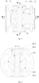
FIG. 1 is a schematic structural view according toEmbodiment 1 of the present disclosure; -
FIG. 2 is a sectional view along A-A inFIG. 1 ; -
FIG. 3 is a schematic structural view according toEmbodiment 2 of the present disclosure; -
FIG. 4 is a sectional view along C-C inFIG. 3 ; -
FIG. 5 is a sectional view along B-B inFIG. 1 ; -
FIG. 6 is a sectional view along D-D inFIG. 3 ; -
FIG. 7 is a schematic view illustrating an integral structure of a rolling element and an inner ring of a TRB in a split socket; -
FIG. 8 is a schematic view illustrating an integral structure of a rolling element and an inner ring of a TRB in an integral socket; -
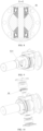
FIG. 9 is a perspective view of an integral ball-and-socket structure; -
FIG. 10 is an exploded view of an integral ball-and-socket structure; -
FIG. 11 is a perspective view of a split ball-and-socket structure; -
FIG. 12 is an exploded view of a split ball-and-socket structure; -
FIG. 13 is a schematic view illustrating that two fit pairs of ball and socket are paired for use, where a transmission shaft is stretched and retracted along a length direction; -
FIG. 14 is a schematic view illustrating that two sockets are integrated oppositely and symmetrically for use; and -
FIG. 15 is a schematic view illustrating a state that a ball of a transmission shaft rotates in a socket for a certain angle for transmission, where an included angle is formed between an axis of a ball handle and an axis of a socket. - In the figures: Q: ball, Q-1: transmission hole, Q-2: outer spherical surface of ball, Q-3:ball handle, Q-4: mouth-shaped surface, S: straight shaft, W: socket, W-1: inner positioning spherical surface, W-2: bearing hole, Z: bearing, M: rolling element, M-1: contact generatrix, G: dust cover, and C: transmission shaft.
- The present invention is further described below by referring to the accompanying drawings.
- As shown in
FIGS. 1-2 , a ball-hinged transmission shaft with a straight shaft includes socket W, ball Q, and straight shaft S. Outer spherical surface Q-2 of the ball is positioned and limited in inner positioning spherical surface W-1 of the socket to form a sliding fit pair. Transmission hole Q-1 is formed in the ball. Mouth-shaped surface Q-4 is further respectively provided at two ends of the transmission hole, as shown inFIG. 1 . Rolling element M is further coaxially provided on the straight shaft. The rolling element is a tapered element with an axis of the straight shaft as the center of rotation. The straight shaft passes through the transmission hole of the ball with two ends each hinged into bearing hole W-2 of the socket through bearing Z and limiting an axial position of the rolling element. An outer tapered surface of the rolling element matches the mouth-shaped surface at the two ends of the transmission hole of the ball. Contact generatrix M-1 between the rolling element and the mouth-shaped surface is a straight line with an extended line passing through the center of the ball. - As shown in
FIG. 2 , the ball Q is restricted by the inner positioning spherical surface W-1 of the socket, the straight shaft S, and the rolling element M at the same time. Ball handle Q-3 of the ball Q may swing around the center of the inner positioning spherical surface of the socket. The rolling element may rotate around the axis of the straight shaft, while rolling along the mouth-shaped surface of the transmission hole, thereby transmitting a power or a rotational speed between the ball and the socket in a state where a certain included angle is formed between an axis of the ball handle and an axis of the socket, as shown inFIG. 15 . - In the embodiment, the rolling element is the tapered element, and the extended line of the contact generatrix between the rolling element and the mouth-shaped surface passes through the center of the ball. When the specific included angle is kept between the axis of the ball handle and the axis of the socket to transmit the power, the rolling element can keep rolling on the mouth-shaped surface, which reduces or prevents sliding friction between the rolling element and the mouth-shaped contact surface, reduces abrasion and heating of the mouth-shaped surface and the rolling element, and prolongs the service life of the product.
- As shown in
FIGS. 3-4 ,Embodiment 2 is a variation ofEmbodiment 1 with the following main differences: The rolling element has a different shape. InEmbodiment 2, the outer surface of the rolling element matching the mouth-shaped surface of the transmission hole is a revolution curved surface, and a contact generatrix between the revolution curved surface and the mouth-shaped surface of the transmission hole is a curved line. The curved line may be an arc, a hyperbolic curve, an involute, and so on as required. In this way, the effective contact area between the rolling element and the mouth-shaped surface of the transmission hole of the ball in power transmission can be increased, the contact stress can be reduced, and the service life of the product can be prolonged. - As shown in
FIG. 5, FIG. 6 , andFIGS. 9-12 , the socket may be of an integral structure or a split structure.FIG. 5 ,FIG. 9, and FIG. 10 show the integral structure, whileFIG. 6 ,FIG. 11, and FIG. 12 show the split structure. Other descriptions are similar to the above and will not be repeated herein. - As shown in
FIG. 7 andFIG. 8 , the bearing may be a TRB. The rolling element may be integrated with an inner ring of the TRB to use fewer components and achieve a simpler structure, a better quality and a lower cost. Other descriptions are similar to the above and will not be repeated herein. -
FIG. 13 is a schematic view illustrating that two fit pairs of ball and socket are paired for use. Two sockets are respectively arranged at two ends of a transmission shaft C assembly. The transmission shaft may be stretched and retracted in the length direction through cooperation between a spline shaft and a spline housing to adapt to a mounting distance of the transmission shaft. Dust cover G is sleeved on the spline shaft and the spline housing and configured to prevent dust and seal a lubricant. Certainly, the extension or retraction of the transmission shaft may also be realized in other manners and is not limited to the above manner. To make the transmission more stable, the straight shaft must keep the same mounting direction. Other descriptions are similar to the above and will not be repeated herein. -
FIG. 14 is a schematic view illustrating that two back-to-back sockets are integrated for use. Two balls are respectively at two ends of a transmission shaft assembly and are docked with a transmission system through ball handles. Other descriptions are similar to the above and will not be repeated herein. - In the description of the present disclosure, orientations or position relationships indicated by terms such as "front end", "rear end", "left", "right", "upper", "lower", and "horizontal" are shown in the drawings. These terms are merely used to facilitate and simplify the description, rather than to indicate or imply that the mentioned apparatus or elements must have a specific orientation and must be established and operated in a specific orientation. Therefore, these terms should not be understood as a limitation of the present disclosure.
- In the description of the present disclosure, it should be noted that, unless otherwise clearly specified and defined, meanings of the terms "arrange", "install", "connected with", "connected to", and "communicate" should be understood in a broad sense. For example, the connection may be a fixed, removable, or integral connection; a mechanical or an electrical connection; may be a direct or an indirect connection by using an intermediate medium; or intercommunication between two components. Those of ordinary skill in the art may deduce specific meanings of the foregoing terms in the present disclosure based on a specific situation.
Claims (10)
- A ball-hinged transmission shaft with a straight shaft, comprising a socket (W), a ball (Q), and a straight shaft (S), wherein an outer spherical surface (Q-2) of the ball is positioned and limited in an inner positioning spherical surface (W-1) of the socket (W) to form a sliding fit pair; a transmission hole (Q-1) is formed in the ball (Q); after passing through the transmission hole (Q-1) of the ball (Q), the straight shaft (S) is hinged into a bearing hole (W-2) of the socket (W) through a bearing (Z); a rolling element (M) is further coaxially provided on the straight shaft (S); the rolling element (M) is a rotator with an axis of the straight shaft (S) as a center of rotation; an outside of the rolling element (M) is connected to the bearing (Z); a mouth-shaped surface (Q-4) is further provided at two ends of the transmission hole (Q-1) of the ball (Q); the mouth-shaped surface (Q-4) is a curved surface matching a shape of the rolling element (M); the rolling element (M) is fit and provided in the mouth-shaped surface (Q-4) at the two ends of the transmission hole (Q-1) of the ball (Q); and the ball (Q) is restricted by the inner positioning spherical surface (W-1) of the socket (W), the straight shaft (S), and the rolling element (M) at the same time.
- The ball-hinged transmission shaft with a straight shaft according to claim 1, wherein an outer surface of the rolling element (M) matching the mouth-shaped surface (Q-4) is a tapered surface, and a contact generatrix (M-1) between the tapered surface and the mouth-shaped surface (Q-4) is a straight line.
- The ball-hinged transmission shaft with a straight shaft according to claim 2, wherein an extended line of the contact generatrix (M-1) passes through a center of the inner spherical surface of the socket (W).
- The ball-hinged transmission shaft with a straight shaft according to claim 1, wherein an outer surface of the rolling element (M) matching the mouth-shaped surface (Q-4) is a revolution curved surface, and a contact generatrix (M-1) between the revolution curved surface and the mouth-shaped surface (Q-4) is a curved line.
- The ball-hinged transmission shaft with a straight shaft according to claim 4, wherein the contact generatrix (M-1) is an arc, a hyperbolic curve, or an involute.
- The ball-hinged transmission shaft with a straight shaft according to any one of claims 1 to 5, wherein the bearing (Z) is a tapered roller bearing (TRB).
- The ball-hinged transmission shaft with a straight shaft according to any one of claims 1 to 5, wherein the bearing (Z) is a TRB, and the rolling element (M) and an inner ring of the bearing (Z) are of an integral structure.
- The ball-hinged transmission shaft with a straight shaft according to claim 1, wherein the socket (W) is of an integral or split structure.
- The ball-hinged transmission shaft with a straight shaft according to claim 1, wherein two fit pairs of ball (Q) and socket (W) are paired for use, two sockets (W) are respectively arranged at two ends of a transmission shaft (C) assembly, the transmission shaft (C) comprises a spline shaft and a spline housing, and the transmission shaft is stretched and retracted through a cooperation between the spline shaft and the spline housing.
- The ball-hinged transmission shaft with a straight shaft according to claim 1, wherein two sockets (W) are connected oppositely and symmetrically, and integrated for use.
Applications Claiming Priority (2)
| Application Number | Priority Date | Filing Date | Title |
|---|---|---|---|
| CN202021793026.3U CN213176523U (en) | 2020-08-20 | 2020-08-20 | Straight-shaft type spherical hinge transmission shaft |
| PCT/CN2021/109954 WO2022037399A1 (en) | 2020-08-20 | 2021-08-02 | Rod-shaped shaft-type ball joint transmission shaft |
Publications (4)
| Publication Number | Publication Date |
|---|---|
| EP4160036A1 EP4160036A1 (en) | 2023-04-05 |
| EP4160036A4 EP4160036A4 (en) | 2023-10-18 |
| EP4160036B1 true EP4160036B1 (en) | 2024-05-01 |
| EP4160036C0 EP4160036C0 (en) | 2024-05-01 |
Family
ID=75767540
Family Applications (1)
| Application Number | Title | Priority Date | Filing Date |
|---|---|---|---|
| EP21857494.5A Active EP4160036B1 (en) | 2020-08-20 | 2021-08-02 | Ball-hinged transmission shaft with straight shaft |
Country Status (5)
| Country | Link |
|---|---|
| US (1) | US11761491B2 (en) |
| EP (1) | EP4160036B1 (en) |
| JP (1) | JP7325153B2 (en) |
| CN (1) | CN213176523U (en) |
| WO (1) | WO2022037399A1 (en) |
Families Citing this family (2)
| Publication number | Priority date | Publication date | Assignee | Title |
|---|---|---|---|---|
| CN213176523U (en) * | 2020-08-20 | 2021-05-11 | 青岛极致创新科技有限公司 | Straight-shaft type spherical hinge transmission shaft |
| US20250146538A1 (en) * | 2022-01-28 | 2025-05-08 | Qingdao Acme Innovation Technology Co., Ltd. | Lightweight universal joint, splined pair, and propeller shaft |
Family Cites Families (25)
| Publication number | Priority date | Publication date | Assignee | Title |
|---|---|---|---|---|
| FR355120A (en) * | 1905-06-09 | 1905-10-24 | Electric & Train Lighting Syndicate Limited | Universal joint |
| GB458006A (en) * | 1935-04-17 | 1936-12-10 | Alexander Petrus Antonius Ten | Improvements in universal couplings |
| US2305594A (en) * | 1941-05-15 | 1942-12-22 | Earl R Backus | Roll mill impact equalizer for flexible couplings |
| US2709901A (en) * | 1953-03-18 | 1955-06-07 | Charles E Forsythe | Flexible coupling |
| SE336935B (en) * | 1966-06-21 | 1971-07-19 | Skf Svenska Kullagerfab Ab | |
| US3609994A (en) * | 1969-10-01 | 1971-10-05 | Trw Inc | Universal joint |
| ES186733Y (en) * | 1972-12-13 | 1974-06-01 | Granell Vercher, Rovira Bayo | PERFECTED CARDANIC JOINT. |
| US4114401A (en) * | 1977-01-24 | 1978-09-19 | Hoose William E Van | Universal joint embodying oscillating drive pin |
| US4151728A (en) | 1978-01-16 | 1979-05-01 | Kimball Brian E | Universal coupling |
| EP0048564A3 (en) | 1980-09-23 | 1982-10-20 | Automotive Products Public Limited Company | Universal joints |
| GB2094440A (en) * | 1981-03-05 | 1982-09-15 | Granway Engineering Ltd | Universal joints |
| GB2139319B (en) * | 1983-05-04 | 1987-12-16 | Tokai Trw & Co | Universal joint |
| DE19843333A1 (en) | 1998-09-22 | 2000-06-15 | Armatec Fts Armaturen | Universal ball joint for pump operation has clutch capable of angular movement forming a link between power plant and power take-off point with bolt fitted through the hole |
| TW201026975A (en) * | 2009-01-06 | 2010-07-16 | Hou-Fei Hu | Universal joint |
| CN202360621U (en) | 2011-11-17 | 2012-08-01 | 资阳南车传动有限公司 | Cross shaft type universal coupling for large-sized rolling and grinding machine |
| CN102518689A (en) | 2011-12-29 | 2012-06-27 | 江苏大学 | High-precision spherical hinge structure for parallel machine tools |
| US20150094157A1 (en) * | 2013-09-27 | 2015-04-02 | Kenneth A. Lock | Rotational connector device |
| US9664237B2 (en) * | 2014-10-31 | 2017-05-30 | Steering Solutions Ip Holding Corporation | Sector journal bearing |
| GB2556235B (en) * | 2015-06-11 | 2019-08-21 | Punk Couplings Ltd | Coupling seal |
| CN106969058A (en) * | 2016-06-22 | 2017-07-21 | 朱德伟 | A kind of ball pivot power transmission shaft |
| CN107605980A (en) * | 2017-07-27 | 2018-01-19 | 朱德伟 | One word shaft type power transmission shaft |
| CN207333486U (en) | 2017-07-27 | 2018-05-08 | 朱德伟 | One word shaft type transmission shaft |
| US20190293112A1 (en) * | 2018-03-26 | 2019-09-26 | Jhih-Sheng TSAI | Universal joint socket |
| US11629760B2 (en) * | 2019-10-04 | 2023-04-18 | Angle X, Inc. | Mechanical joints and applications |
| CN213176523U (en) | 2020-08-20 | 2021-05-11 | 青岛极致创新科技有限公司 | Straight-shaft type spherical hinge transmission shaft |
-
2020
- 2020-08-20 CN CN202021793026.3U patent/CN213176523U/en active Active
-
2021
- 2021-08-02 WO PCT/CN2021/109954 patent/WO2022037399A1/en not_active Ceased
- 2021-08-02 US US18/009,992 patent/US11761491B2/en active Active
- 2021-08-02 JP JP2023502729A patent/JP7325153B2/en active Active
- 2021-08-02 EP EP21857494.5A patent/EP4160036B1/en active Active
Also Published As
| Publication number | Publication date |
|---|---|
| US11761491B2 (en) | 2023-09-19 |
| CN213176523U (en) | 2021-05-11 |
| EP4160036A4 (en) | 2023-10-18 |
| JP2023527589A (en) | 2023-06-29 |
| JP7325153B2 (en) | 2023-08-14 |
| EP4160036A1 (en) | 2023-04-05 |
| US20230213069A1 (en) | 2023-07-06 |
| WO2022037399A1 (en) | 2022-02-24 |
| EP4160036C0 (en) | 2024-05-01 |
Similar Documents
| Publication | Publication Date | Title |
|---|---|---|
| EP4160036A1 (en) | Rod-shaped shaft-type ball joint transmission shaft | |
| US4203511A (en) | Device for moving objects along a predetermined path | |
| EP1413787A3 (en) | Tripod type constant velocity joint | |
| US20220407273A1 (en) | Electrical contact arrangement | |
| DE502006000297D1 (en) | DRIVE SPINDLE FOR THE MAIN DRIVE OF A WHEEL RACK | |
| CN210461621U (en) | Steering box body | |
| CN220410080U (en) | Printing rubber roll quick change structure and printing equipment | |
| CN117463440A (en) | Can eliminate three-roller machine of swing arm bearing oil clearance | |
| US4480454A (en) | Skew-rolling mill for reducing solid and hollow cross-sections | |
| CN209765081U (en) | Communication pipeline burial depth detection device | |
| CN220540120U (en) | Two-way balance shaft sleeve for gear motor | |
| US2580669A (en) | Continuous change-speed gear | |
| CN222142643U (en) | An adjustable mounting mechanism for a digital differential pressure gauge | |
| CN218207694U (en) | Novel side plate single pulley or coaxial double pulleys for increasing rotation friction force | |
| CN220706235U (en) | Double-station rotary transmission ball spline | |
| CN219975264U (en) | Rotating shaft fastening mechanism | |
| KR100428049B1 (en) | Pulley Type Constant Velocity Joint | |
| CN220452539U (en) | Novel ball cage type synchronous universal coupling | |
| CN219013055U (en) | Supporting shaft of hydraulic motor | |
| CN214324808U (en) | A luggage pulley with increased stability | |
| CN214639124U (en) | A rolling mill and its electric roll gap adjustment device | |
| CN215596235U (en) | Cross axle universal joint convenient to adjust installation | |
| CN217837907U (en) | Guide wheel structure with adjustable size for cable production | |
| CN214578423U (en) | Detachable inner ball cage | |
| CA2393822A1 (en) | Roller head for a planetary rolling mill |
Legal Events
| Date | Code | Title | Description |
|---|---|---|---|
| STAA | Information on the status of an ep patent application or granted ep patent |
Free format text: STATUS: THE INTERNATIONAL PUBLICATION HAS BEEN MADE |
|
| PUAI | Public reference made under article 153(3) epc to a published international application that has entered the european phase |
Free format text: ORIGINAL CODE: 0009012 |
|
| STAA | Information on the status of an ep patent application or granted ep patent |
Free format text: STATUS: REQUEST FOR EXAMINATION WAS MADE |
|
| 17P | Request for examination filed |
Effective date: 20221229 |
|
| AK | Designated contracting states |
Kind code of ref document: A1 Designated state(s): AL AT BE BG CH CY CZ DE DK EE ES FI FR GB GR HR HU IE IS IT LI LT LU LV MC MK MT NL NO PL PT RO RS SE SI SK SM TR |
|
| A4 | Supplementary search report drawn up and despatched |
Effective date: 20230914 |
|
| RIC1 | Information provided on ipc code assigned before grant |
Ipc: F16D 3/16 20060101ALI20230908BHEP Ipc: F16D 3/26 20060101AFI20230908BHEP |
|
| DAV | Request for validation of the european patent (deleted) | ||
| DAX | Request for extension of the european patent (deleted) | ||
| GRAP | Despatch of communication of intention to grant a patent |
Free format text: ORIGINAL CODE: EPIDOSNIGR1 |
|
| STAA | Information on the status of an ep patent application or granted ep patent |
Free format text: STATUS: GRANT OF PATENT IS INTENDED |
|
| INTG | Intention to grant announced |
Effective date: 20240110 |
|
| GRAS | Grant fee paid |
Free format text: ORIGINAL CODE: EPIDOSNIGR3 |
|
| GRAA | (expected) grant |
Free format text: ORIGINAL CODE: 0009210 |
|
| STAA | Information on the status of an ep patent application or granted ep patent |
Free format text: STATUS: THE PATENT HAS BEEN GRANTED |
|
| AK | Designated contracting states |
Kind code of ref document: B1 Designated state(s): AL AT BE BG CH CY CZ DE DK EE ES FI FR GB GR HR HU IE IS IT LI LT LU LV MC MK MT NL NO PL PT RO RS SE SI SK SM TR |
|
| REG | Reference to a national code |
Ref country code: GB Ref legal event code: FG4D |
|
| REG | Reference to a national code |
Ref country code: CH Ref legal event code: EP |
|
| REG | Reference to a national code |
Ref country code: IE Ref legal event code: FG4D |
|
| REG | Reference to a national code |
Ref country code: DE Ref legal event code: R096 Ref document number: 602021012870 Country of ref document: DE |
|
| U01 | Request for unitary effect filed |
Effective date: 20240507 |
|
| U07 | Unitary effect registered |
Designated state(s): AT BE BG DE DK EE FI FR IT LT LU LV MT NL PT SE SI Effective date: 20240522 |
|
| U20 | Renewal fee for the european patent with unitary effect paid |
Year of fee payment: 4 Effective date: 20240731 |
|
| PG25 | Lapsed in a contracting state [announced via postgrant information from national office to epo] |
Ref country code: IS Free format text: LAPSE BECAUSE OF FAILURE TO SUBMIT A TRANSLATION OF THE DESCRIPTION OR TO PAY THE FEE WITHIN THE PRESCRIBED TIME-LIMIT Effective date: 20240901 |
|
| PG25 | Lapsed in a contracting state [announced via postgrant information from national office to epo] |
Ref country code: HR Free format text: LAPSE BECAUSE OF FAILURE TO SUBMIT A TRANSLATION OF THE DESCRIPTION OR TO PAY THE FEE WITHIN THE PRESCRIBED TIME-LIMIT Effective date: 20240501 |
|
| PG25 | Lapsed in a contracting state [announced via postgrant information from national office to epo] |
Ref country code: GR Free format text: LAPSE BECAUSE OF FAILURE TO SUBMIT A TRANSLATION OF THE DESCRIPTION OR TO PAY THE FEE WITHIN THE PRESCRIBED TIME-LIMIT Effective date: 20240802 |
|
| PG25 | Lapsed in a contracting state [announced via postgrant information from national office to epo] |
Ref country code: ES Free format text: LAPSE BECAUSE OF FAILURE TO SUBMIT A TRANSLATION OF THE DESCRIPTION OR TO PAY THE FEE WITHIN THE PRESCRIBED TIME-LIMIT Effective date: 20240501 |
|
| PG25 | Lapsed in a contracting state [announced via postgrant information from national office to epo] |
Ref country code: PL Free format text: LAPSE BECAUSE OF FAILURE TO SUBMIT A TRANSLATION OF THE DESCRIPTION OR TO PAY THE FEE WITHIN THE PRESCRIBED TIME-LIMIT Effective date: 20240501 |
|
| PG25 | Lapsed in a contracting state [announced via postgrant information from national office to epo] |
Ref country code: PL Free format text: LAPSE BECAUSE OF FAILURE TO SUBMIT A TRANSLATION OF THE DESCRIPTION OR TO PAY THE FEE WITHIN THE PRESCRIBED TIME-LIMIT Effective date: 20240501 Ref country code: NO Free format text: LAPSE BECAUSE OF FAILURE TO SUBMIT A TRANSLATION OF THE DESCRIPTION OR TO PAY THE FEE WITHIN THE PRESCRIBED TIME-LIMIT Effective date: 20240801 Ref country code: IS Free format text: LAPSE BECAUSE OF FAILURE TO SUBMIT A TRANSLATION OF THE DESCRIPTION OR TO PAY THE FEE WITHIN THE PRESCRIBED TIME-LIMIT Effective date: 20240901 Ref country code: HR Free format text: LAPSE BECAUSE OF FAILURE TO SUBMIT A TRANSLATION OF THE DESCRIPTION OR TO PAY THE FEE WITHIN THE PRESCRIBED TIME-LIMIT Effective date: 20240501 Ref country code: GR Free format text: LAPSE BECAUSE OF FAILURE TO SUBMIT A TRANSLATION OF THE DESCRIPTION OR TO PAY THE FEE WITHIN THE PRESCRIBED TIME-LIMIT Effective date: 20240802 Ref country code: ES Free format text: LAPSE BECAUSE OF FAILURE TO SUBMIT A TRANSLATION OF THE DESCRIPTION OR TO PAY THE FEE WITHIN THE PRESCRIBED TIME-LIMIT Effective date: 20240501 Ref country code: RS Free format text: LAPSE BECAUSE OF FAILURE TO SUBMIT A TRANSLATION OF THE DESCRIPTION OR TO PAY THE FEE WITHIN THE PRESCRIBED TIME-LIMIT Effective date: 20240801 |
|
| PG25 | Lapsed in a contracting state [announced via postgrant information from national office to epo] |
Ref country code: CZ Free format text: LAPSE BECAUSE OF FAILURE TO SUBMIT A TRANSLATION OF THE DESCRIPTION OR TO PAY THE FEE WITHIN THE PRESCRIBED TIME-LIMIT Effective date: 20240501 |
|
| PG25 | Lapsed in a contracting state [announced via postgrant information from national office to epo] |
Ref country code: RO Free format text: LAPSE BECAUSE OF FAILURE TO SUBMIT A TRANSLATION OF THE DESCRIPTION OR TO PAY THE FEE WITHIN THE PRESCRIBED TIME-LIMIT Effective date: 20240501 Ref country code: SK Free format text: LAPSE BECAUSE OF FAILURE TO SUBMIT A TRANSLATION OF THE DESCRIPTION OR TO PAY THE FEE WITHIN THE PRESCRIBED TIME-LIMIT Effective date: 20240501 |
|
| PG25 | Lapsed in a contracting state [announced via postgrant information from national office to epo] |
Ref country code: SM Free format text: LAPSE BECAUSE OF FAILURE TO SUBMIT A TRANSLATION OF THE DESCRIPTION OR TO PAY THE FEE WITHIN THE PRESCRIBED TIME-LIMIT Effective date: 20240501 |
|
| PG25 | Lapsed in a contracting state [announced via postgrant information from national office to epo] |
Ref country code: SM Free format text: LAPSE BECAUSE OF FAILURE TO SUBMIT A TRANSLATION OF THE DESCRIPTION OR TO PAY THE FEE WITHIN THE PRESCRIBED TIME-LIMIT Effective date: 20240501 Ref country code: SK Free format text: LAPSE BECAUSE OF FAILURE TO SUBMIT A TRANSLATION OF THE DESCRIPTION OR TO PAY THE FEE WITHIN THE PRESCRIBED TIME-LIMIT Effective date: 20240501 Ref country code: RO Free format text: LAPSE BECAUSE OF FAILURE TO SUBMIT A TRANSLATION OF THE DESCRIPTION OR TO PAY THE FEE WITHIN THE PRESCRIBED TIME-LIMIT Effective date: 20240501 Ref country code: CZ Free format text: LAPSE BECAUSE OF FAILURE TO SUBMIT A TRANSLATION OF THE DESCRIPTION OR TO PAY THE FEE WITHIN THE PRESCRIBED TIME-LIMIT Effective date: 20240501 |
|
| REG | Reference to a national code |
Ref country code: DE Ref legal event code: R097 Ref document number: 602021012870 Country of ref document: DE |
|
| PLBE | No opposition filed within time limit |
Free format text: ORIGINAL CODE: 0009261 |
|
| STAA | Information on the status of an ep patent application or granted ep patent |
Free format text: STATUS: NO OPPOSITION FILED WITHIN TIME LIMIT |
|
| REG | Reference to a national code |
Ref country code: CH Ref legal event code: PL |
|
| 26N | No opposition filed |
Effective date: 20250204 |
|
| PG25 | Lapsed in a contracting state [announced via postgrant information from national office to epo] |
Ref country code: MC Free format text: LAPSE BECAUSE OF FAILURE TO SUBMIT A TRANSLATION OF THE DESCRIPTION OR TO PAY THE FEE WITHIN THE PRESCRIBED TIME-LIMIT Effective date: 20240501 Ref country code: CH Free format text: LAPSE BECAUSE OF NON-PAYMENT OF DUE FEES Effective date: 20240831 |
|
| PG25 | Lapsed in a contracting state [announced via postgrant information from national office to epo] |
Ref country code: IE Free format text: LAPSE BECAUSE OF NON-PAYMENT OF DUE FEES Effective date: 20240802 |
|
| U20 | Renewal fee for the european patent with unitary effect paid |
Year of fee payment: 5 Effective date: 20250826 |
|
| PGFP | Annual fee paid to national office [announced via postgrant information from national office to epo] |
Ref country code: GB Payment date: 20250826 Year of fee payment: 5 |
|
| PG25 | Lapsed in a contracting state [announced via postgrant information from national office to epo] |
Ref country code: CY Free format text: LAPSE BECAUSE OF FAILURE TO SUBMIT A TRANSLATION OF THE DESCRIPTION OR TO PAY THE FEE WITHIN THE PRESCRIBED TIME-LIMIT; INVALID AB INITIO Effective date: 20210802 |
|
| PG25 | Lapsed in a contracting state [announced via postgrant information from national office to epo] |
Ref country code: HU Free format text: LAPSE BECAUSE OF FAILURE TO SUBMIT A TRANSLATION OF THE DESCRIPTION OR TO PAY THE FEE WITHIN THE PRESCRIBED TIME-LIMIT; INVALID AB INITIO Effective date: 20210802 |