EP4160024A1 - Pump casing and pump device - Google Patents
Pump casing and pump device Download PDFInfo
- Publication number
- EP4160024A1 EP4160024A1 EP21814159.6A EP21814159A EP4160024A1 EP 4160024 A1 EP4160024 A1 EP 4160024A1 EP 21814159 A EP21814159 A EP 21814159A EP 4160024 A1 EP4160024 A1 EP 4160024A1
- Authority
- EP
- European Patent Office
- Prior art keywords
- suction
- suction nozzle
- pump casing
- impeller
- pump
- Prior art date
- Legal status (The legal status is an assumption and is not a legal conclusion. Google has not performed a legal analysis and makes no representation as to the accuracy of the status listed.)
- Pending
Links
- 239000007788 liquid Substances 0.000 claims description 112
- 230000002093 peripheral effect Effects 0.000 claims description 13
- 238000007789 sealing Methods 0.000 description 43
- 239000002002 slurry Substances 0.000 description 18
- 239000012530 fluid Substances 0.000 description 9
- XLYOFNOQVPJJNP-UHFFFAOYSA-N water Substances O XLYOFNOQVPJJNP-UHFFFAOYSA-N 0.000 description 9
- 238000001816 cooling Methods 0.000 description 6
- 230000000694 effects Effects 0.000 description 6
- 239000008399 tap water Substances 0.000 description 5
- 235000020679 tap water Nutrition 0.000 description 5
- 238000004140 cleaning Methods 0.000 description 4
- 230000000052 comparative effect Effects 0.000 description 4
- 230000005484 gravity Effects 0.000 description 4
- 238000004804 winding Methods 0.000 description 3
- 239000008235 industrial water Substances 0.000 description 2
- 230000000717 retained effect Effects 0.000 description 2
- 239000002699 waste material Substances 0.000 description 2
- 239000008186 active pharmaceutical agent Substances 0.000 description 1
- 230000002411 adverse Effects 0.000 description 1
- 238000007664 blowing Methods 0.000 description 1
- 238000005260 corrosion Methods 0.000 description 1
- 230000007797 corrosion Effects 0.000 description 1
- 238000007599 discharging Methods 0.000 description 1
- 230000001050 lubricating effect Effects 0.000 description 1
- 238000012423 maintenance Methods 0.000 description 1
- 239000000463 material Substances 0.000 description 1
- 238000000034 method Methods 0.000 description 1
- 239000000203 mixture Substances 0.000 description 1
- 238000012986 modification Methods 0.000 description 1
- 230000004048 modification Effects 0.000 description 1
- 238000005086 pumping Methods 0.000 description 1
- 229910001220 stainless steel Inorganic materials 0.000 description 1
- 239000010935 stainless steel Substances 0.000 description 1
Images






Classifications
-
- F—MECHANICAL ENGINEERING; LIGHTING; HEATING; WEAPONS; BLASTING
- F04—POSITIVE - DISPLACEMENT MACHINES FOR LIQUIDS; PUMPS FOR LIQUIDS OR ELASTIC FLUIDS
- F04D—NON-POSITIVE-DISPLACEMENT PUMPS
- F04D29/00—Details, component parts, or accessories
- F04D29/40—Casings; Connections of working fluid
- F04D29/42—Casings; Connections of working fluid for radial or helico-centrifugal pumps
- F04D29/426—Casings; Connections of working fluid for radial or helico-centrifugal pumps especially adapted for liquid pumps
- F04D29/4293—Details of fluid inlet or outlet
-
- F—MECHANICAL ENGINEERING; LIGHTING; HEATING; WEAPONS; BLASTING
- F04—POSITIVE - DISPLACEMENT MACHINES FOR LIQUIDS; PUMPS FOR LIQUIDS OR ELASTIC FLUIDS
- F04D—NON-POSITIVE-DISPLACEMENT PUMPS
- F04D13/00—Pumping installations or systems
- F04D13/02—Units comprising pumps and their driving means
- F04D13/06—Units comprising pumps and their driving means the pump being electrically driven
-
- F—MECHANICAL ENGINEERING; LIGHTING; HEATING; WEAPONS; BLASTING
- F04—POSITIVE - DISPLACEMENT MACHINES FOR LIQUIDS; PUMPS FOR LIQUIDS OR ELASTIC FLUIDS
- F04D—NON-POSITIVE-DISPLACEMENT PUMPS
- F04D29/00—Details, component parts, or accessories
- F04D29/40—Casings; Connections of working fluid
- F04D29/42—Casings; Connections of working fluid for radial or helico-centrifugal pumps
- F04D29/426—Casings; Connections of working fluid for radial or helico-centrifugal pumps especially adapted for liquid pumps
-
- F—MECHANICAL ENGINEERING; LIGHTING; HEATING; WEAPONS; BLASTING
- F04—POSITIVE - DISPLACEMENT MACHINES FOR LIQUIDS; PUMPS FOR LIQUIDS OR ELASTIC FLUIDS
- F04D—NON-POSITIVE-DISPLACEMENT PUMPS
- F04D29/00—Details, component parts, or accessories
- F04D29/60—Mounting; Assembling; Disassembling
- F04D29/605—Mounting; Assembling; Disassembling specially adapted for liquid pumps
-
- F—MECHANICAL ENGINEERING; LIGHTING; HEATING; WEAPONS; BLASTING
- F04—POSITIVE - DISPLACEMENT MACHINES FOR LIQUIDS; PUMPS FOR LIQUIDS OR ELASTIC FLUIDS
- F04D—NON-POSITIVE-DISPLACEMENT PUMPS
- F04D29/00—Details, component parts, or accessories
- F04D29/60—Mounting; Assembling; Disassembling
- F04D29/62—Mounting; Assembling; Disassembling of radial or helico-centrifugal pumps
- F04D29/628—Mounting; Assembling; Disassembling of radial or helico-centrifugal pumps especially adapted for liquid pumps
-
- F—MECHANICAL ENGINEERING; LIGHTING; HEATING; WEAPONS; BLASTING
- F04—POSITIVE - DISPLACEMENT MACHINES FOR LIQUIDS; PUMPS FOR LIQUIDS OR ELASTIC FLUIDS
- F04D—NON-POSITIVE-DISPLACEMENT PUMPS
- F04D7/00—Pumps adapted for handling specific fluids, e.g. by selection of specific materials for pumps or pump parts
- F04D7/02—Pumps adapted for handling specific fluids, e.g. by selection of specific materials for pumps or pump parts of centrifugal type
- F04D7/06—Pumps adapted for handling specific fluids, e.g. by selection of specific materials for pumps or pump parts of centrifugal type the fluids being hot or corrosive, e.g. liquid metals
-
- F—MECHANICAL ENGINEERING; LIGHTING; HEATING; WEAPONS; BLASTING
- F05—INDEXING SCHEMES RELATING TO ENGINES OR PUMPS IN VARIOUS SUBCLASSES OF CLASSES F01-F04
- F05D—INDEXING SCHEME FOR ASPECTS RELATING TO NON-POSITIVE-DISPLACEMENT MACHINES OR ENGINES, GAS-TURBINES OR JET-PROPULSION PLANTS
- F05D2260/00—Function
- F05D2260/60—Fluid transfer
- F05D2260/602—Drainage
Definitions
- the present invention relates to a pump casing and a pump apparatus.
- a pump apparatus includes a rotational shaft, an impeller fixed to the rotational shaft, a motor that rotates the impeller together with the rotational shaft, and a pump casing having a suction port and a discharge port and housing the impeller (see for example Patent Document 1).
- the pump apparatus is periodically disassembled and cleaned in order to maintain the quality of the liquid to be conveyed.
- the pump is removed from a pipe and an inside of the pump casing is cleaned, it is necessary to completely remove a liquid remaining in the pump casing.
- the removed pump is moved, there is a concern that the liquid remaining in the pump casing will contaminate the surroundings.
- a pump casing having a suction port connected to a horizontally extending suction pipe, comprising: a suction nozzle with formed the suction port, and the suction nozzle sloping downward toward the suction port.
- the suction port is a bottom portion in the pump casing.
- the pump casing comprises a volute portion connecting to the suction nozzle, and the suction nozzle has a straight shape extending diagonally downward from the volute portion.
- the suction port is arranged below the volute portion, and a work space for connecting the suction nozzle to the suction pipe is formed between the volute portion and the suction nozzle.
- a pump casing having a suction port and a discharge port, comprising: a suction nozzle with formed the suction port, and the suction nozzle having a drain port at a bottom portion of the suction nozzle.
- a pump apparatus comprising: an impeller; a rotational shaft fixing to the impeller; a motor configured to rotate the rotational shaft; and a pump casing according to above described, the pump casing housing the impeller.
- the pump apparatus comprising a leg portion connected to the pump casing.
- the leg portion forms a space below a suction flange portion having the suction port, the space arranging a drain pan configured to catch a liquid discharged from the suction port.
- the pump casing comprises a suction nozzle with formed the suction port, the suction nozzle has a drain port at a bottom portion of the suction nozzle, and the leg portion forms a space below the drain port, the space arranging a drain pan configured to catch the liquid discharged from the suction port.
- the pump casing comprises a suction nozzle with formed the suction port, the suction nozzle has a drain port at a bottom portion of the suction nozzle, and the leg portion forms a space arranging a pipe connectable to the drain port.
- a pump apparatus comprising: an impeller; a rotational shaft fixing to the impeller; a motor configured to rotate the rotational shaft; and a pump casing housing the impeller, the motor comprises: a bearing configured to rotatably support the rotational shaft; a motor casing having a bearing support portion configured to support the bearing; and a bearing retainer configured to restrict a movement of the bearing in an axial direction of the rotational shaft.
- the bearing retainer is fixed to the bearing support portion.
- the bearing retainer has an annular shape.
- the pump apparatus is a vertical pump apparatus.
- a vertical pump apparatus comprising: an impeller; a rotational shaft fixing to the impeller; an impeller housing structure configured to house the impeller; and a gap adjustment structure configured to adjust a size of a gap between the impeller and the impeller housing structure.
- the gap adjustment structure comprises: a distance piece attached to a stepped portion of the rotational shaft; and at least one shim arranged between the distance piece and the impeller.
- a pump casing comprising: a suction nozzle having a suction port; and a volute portion connecting to the suction nozzle, and the suction nozzle slopes downward from a connection portion connected to the volute portion toward the suction port, and has a flow path whose cross-sectional area increases from the suction port to the connection portion.
- the suction nozzle has a wide portion arranged between the suction port and the connection portion.
- the wide portion extends horizontally.
- a cross-sectional area of the flow path increases at a constant rate of change from the suction port toward the connection portion.
- a pump casing comprising: a suction nozzle having a suction port; and a volute portion connected to a connection portion of the suction nozzle, and the volute portion having a volute chamber, a bottom surface of the volute chamber slopes downward from a peripheral portion of the volute chamber toward the connection portion.
- the suction nozzle slopes downward from the connection portion toward the suction port.
- the suction port is arranged at a position lower than a discharge port of the pump casing.
- the pump casing includes a suction nozzle that can discharge an inside liquid at the bottom portion of the flow path of the pump casing. Therefore, the liquid in the pump casing is discharged outside from the suction nozzle by the action of gravity.
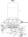
- FIG. 1 is a view showing one embodiment of a pump apparatus.
- the pump apparatus includes a rotational shaft 1 for pressurizing a liquid to be handled (transferred liquid), an impeller 3 fixed to the rotational shaft 1, a pump casing 5 housing the impeller 3, a motor 7 for rotating the rotational shaft 1, an intermediate bracket 50 arranged between the pump casing 5 and the motor 7, and a shaft sealing device 30 for preventing leakage of high-pressure liquid.
- the pump casing 5 includes a suction port 12 and a discharge port 13, and is made of a corrosion-resistant material (e.g., stainless steel).
- a corrosion-resistant material e.g., stainless steel
- the rotational shaft 1 is arranged vertically (see a direction of an axis line CL in FIG. 1 ).
- the intermediate bracket 50 has an opening 50a through which the rotational shaft 1 penetrates, and the shaft sealing device 30 seals the transferred liquid leaking to the outside (i.e., the outside is the motor 7) from the opening 50a through which the rotational shaft 1 penetrates.
- the impeller 3 When the motor 7 is driven, a rotation of the motor 7 is transmitted to the rotational shaft 1, and the rotational shaft 1 and the impeller 3 rotate.
- the impeller 3 rotates, the liquid flows into the pump casing 5 through the suction port 12, and is pressurized as the impeller 3 rotates.
- the pressurized liquid is discharged from the discharge port 13.
- the impeller 3 is a semi-open impeller.
- the impeller 3 may be a vortex impeller or a closed impeller.
- the shaft sealing device 30 is a device that seals a gap between the rotational shaft 1 and the intermediate bracket 50.
- An example of the shaft sealing device 30 includes a double mechanical seal.
- the shaft sealing device 30 includes a rotary side seal member (not shown) fixed to the rotational shaft 1, and a stationary side seal member (not shown) fixed to the intermediate bracket 50. Therefore, when the rotational shaft 1 rotates, the rotary side seal member comes into sliding contact with the stationary side seal member, and the shaft sealing device 30 generates heat.
- the temperature of the liquid to be handled may range from low temperature (e.g., -25°C) to high temperature (e.g., 140°C).
- low temperature e.g., -25°C
- high temperature e.g. 140°C
- the temperature of the liquid to be handled is higher than an allowable temperature of the shaft sealing device 30, if the hot liquid to be handled directly contacts the shaft sealing device 30, the temperature of the shaft sealing device 30 generated by the sliding heat rises further.
- the liquid to be handled includes a slurry liquid containing a slurry of about 0.05 mm.
- the liquid to be handled may include clean water or dirty water.
- the shaft sealing device 30 becomes very hot due to the sliding of the rotary side seal member and the stationary side seal member, and contact with the high-temperature liquid to be handled, and the shaft sealing device 30 may fail.
- the shaft sealing device 30 cannot fully exhibit its function, and the liquid may leak to the motor 7 side, and the motor 7 may be submerged in water. Therefore, in the pump apparatus, a structure capable of reliably preventing failure of the shaft sealing device 30 is desired.
- the pump apparatus includes a normal temperature flow path 60 that keeps the liquid flowing through the shaft sealing device 30 within a predetermined temperature range.
- the pump apparatus includes the normal temperature flow path 60 (second flow path) that keeps the liquid to be handled in the flow path 90 within a predetermined temperature range.
- the opening 50a forms the flow path 90 (first flow path) through which the liquid to be handled flows into the shaft sealing device 30.
- the normal temperature flow path 60 is formed in the intermediate bracket 50. More specifically, the intermediate bracket 50 includes a cover portion 51 covering an opening end 5a of the pump casing 5, and a bracket portion 52 connected to the cover portion 51.
- the normal temperature flow path 60 is formed in at least one of the cover portion 51 and the bracket portion 52.
- the normal temperature flow path 60 is formed in both the cover portion 51 and the bracket portion 52, but in one embodiment, the normal temperature flow path 60 may be formed only in the cover portion 51, or may be formed in the bracket portion 52. That is, the opening 50a is formed at an opening 51a in the cover portion 51 through which the rotational shaft 1 passes and/or the opening 52a in the bracket portion 52 through which the rotational shaft 1 passes.
- the opening 50a forms the flow path 90
- the normal temperature channel 60 is formed adjacent to at least a portion of the opening 50a so that the liquid to be handled in the flow path 90 can be kept within a predetermined temperature range.
- the shaft sealing device 30 determines an allowable temperature range according to its product specifications.
- the predetermined temperature range described as "the liquid to be handled in the flow path 90 can be kept within a predetermined temperature range” means that the temperature of the shaft sealing device 30 is within the allowable range even if the shaft sealing device 30 generates heat due to sliding.
- the normal temperature flow path 60 is arranged radially outward of the flow path 90 formed by an outer peripheral surface of the rotational shaft 1 and an inner peripheral surface (opening 50a) of the intermediate bracket 50.
- the liquid to be handled pressurized by the rotation of the impeller 3 contacts the shaft sealing device 30 after being heat-exchanged by the fluid in the normal temperature flow path 60 separated by a side wall 60a when flowing through the flow path 90.
- the liquid to be handled in the flow path 90 that has been brought to an appropriate temperature by the fluid in the normal temperature flow path 60 can be used for lubricating the shaft sealing device 30. Therefore, the shaft sealing device 30 can prevent leakage to the motor 7 side even if the liquid to be handled is out of the allowable range.
- the normal temperature flow path 60 communicates with a liquid inlet 61 and a liquid outlet 62.
- the liquid e.g., tap water
- the normal temperature liquid e.g., clear water of 0°C to 65°C
- the normal temperature liquid keeps the temperature of the liquid present in the flow path 90 arranged radially inside the normal temperature flow path 60 within a predetermined range (e.g., 0°C to 65°C).
- the high-temperature liquid to be handled is cold by the liquid flowing through the normal temperature flow path 60 (e.g., tap water or industrial water of the normal temperature of 0°C to 35°C).
- the temperature of the liquid to be handled is lower than the allowable range of the shaft sealing device 30 (e.g., minus 25°C)
- the low-temperature liquid to be handled is heated by the liquid flowing through the normal flow path 60 (e.g., tap water or industrial water of the normal temperature of 0°C to 35°C).
- the temperature of the shaft sealing device 30 can be kept within the allowable range.
- the liquid that has flowed into the normal temperature flow path 60 is discharged from the liquid outlet 62.
- the liquid flowing through the normal temperature flow path 60 is an example of a fluid, and examples of the fluid may be tap water, factory water, or gas.
- the fluid in the normal temperature flow path 60 used for adjusting the temperature of the shaft sealing device 30 does not mix with the liquid to be handled pressurized by the impeller 3. Therefore, the temperature of the shaft sealing device 30 can be kept within the allowable range by using a fluid different from the liquid to be handled.
- a user can select the fluid for the normal temperature flow path 60 depending on an equipment and an environment. Therefore, the pump apparatus of this embodiment is particularly effective when the transferred liquid is a special liquid containing slurry or the like.
- the intermediate bracket 50 includes a throttle portion 65 that throttles the flow path of the liquid (i.e., the liquid to be handled) flowing through the shaft sealing device 30.
- the throttle portion 65 shown in FIG. 1 is a member (e.g., a bush) having an annular shape.
- the throttle portion 65 is fixed to the inner peripheral surface of the cover portion 51 which is the inlet of the flow path 90, and arranged concentrically with the rotational shaft 1.
- the throttle portion 65 reduces a flow rate of the liquid to be handled through the flow path 90 by reducing the flow path 90 (i.e., the gap between the throttle portion 65 and the impeller 3) to the shaft sealing device 30.
- the time for heat exchange with the fluid in the room temperature flow path 60 is lengthened, and a cooling effect can be expected.
- a retaining chamber 66 for liquid flowing to the shaft sealing device 30 is formed between the shaft sealing device 30 and the throttle portion 65.
- the retaining chamber 66 is an annular chamber formed between an outer peripheral surface of the rotational shaft 1 and the inner peripheral surface of the cover portion 51, and the liquid that has passed through the gap between the throttle portion 65 and the impeller 3 retains in the retaining chamber 66.
- the liquid to be handled that has flowed into the pump casing 5 due to the rotation of the impeller 3 passes through the small gap between the impeller 3 and the throttle portion 65, and flows into the retaining chamber 66.
- the liquid once flowing into the retaining chamber 66 continues to stay in the retaining chamber 66 until the pressure inside the pump casing 5 is sufficiently lowered.
- the normal temperature flow path 60 is arranged outside the retaining chamber 66, and the retaining chamber 66 communicates with the shaft sealing device 30. More specifically, the normal temperature flow path 60 is an annular flow path surrounding the retaining chamber 66. Therefore, the liquid existing in the retaining chamber 66 is more actively heat-exchanged with the liquid flowing through the normal temperature flow path 60.
- the liquid in contact with the shaft sealing device 30 is retained in the retaining chamber 66 for a long time, and heat is exchanged with the liquid flowing through the normal temperature flow path 60.
- the temperature of the shaft sealing device 30 falls within the allowable range. That is, the liquid to be handled within a predetermined temperature range that allows the temperature of the shaft sealing device 30 to remain in the retaining chamber 66, and the liquid retained in the retaining chamber 66 is used to lubricate the shaft sealing device 30.
- the liquid existing in the retaining chamber 66 prevents the contact of the high-temperature or low-temperature liquid outside the predetermined temperature range with the shaft sealing device 30. As a result, the shaft sealing device 30 can be prevented from failing due to contact with the high-temperature or low-temperature liquid.
- the pump apparatus includes the normal temperature flow path 60 that keeps the liquid flowing through the shaft sealing device 30 within a predetermined temperature range, but means for protecting the shaft sealing device 30 is not limited to this embodiment. In one embodiment, the pump apparatus does not need to include at least one of the normal temperature flow path 60, the throttle portion 65, the retaining chamber 66, etc., as long as the shaft sealing device 30 can be protected.
- the pump apparatus is periodically disassembled and cleaned depending on the intended use. During this disassembly and cleaning, it is necessary to completely remove the liquid inside the pump apparatus. However, since an internal flow path of the pump casing 5 has a complicated shape, it is troublesome to remove the remaining liquid.
- a slurry liquid is included as the liquid to be handled, and the slurry liquid tends to remain in the pump casing 5 when disassembly and cleaning of the pump apparatus. Therefore, in the embodiment described below, the structure of the pump casing 5, which has a simple structure and can be easily washed, will be described with reference to the drawings.
- the pump casing 5 has a suction nozzle 100 with the suction port 12 formed therein.
- the suction port 12 is flange-connected to a horizontally extending a suction pipe S
- the discharge port 13 is flange-connected to a horizontally extending a discharge pipe D by fasteners (e.g., bolts and nuts).
- the pump apparatus is operated in that state.
- the suction nozzle 100 slopes downward toward the suction port 12. More specifically, the pump casing 5 further includes a volute portion 101 to which the suction nozzle 100 is connected, and the suction nozzle 100 slopes downward from the volute portion 101 toward the suction port 12.
- the volute portion 101 forms a volute chamber 102 around the impeller 3 housed in the pump casing 5.
- the transferred liquid pressurized by the impeller 3 in the volute chamber 102 is discharged from the discharge port 13 laterally extending from the volute chamber 102.
- the suction nozzle 100 is connected to the center of a bottom of the volute portion 101, and extends downward from the volute portion 101.
- the suction nozzle 100 includes a connection portion 100a connected to the volute portion 101, a suction flange portion 100b having the suction port 12, and a nozzle portion 100c connected to the connection portion 100a and the suction flange portion 100b.
- the nozzle portion 100c extends obliquely downward from the connection portion 100a toward the suction flange portion 100b, and the suction port 12 of the suction nozzle 100 is arranged below the connection portion 100a of the suction nozzle 100. That is, the suction port 12 is a bottom portion of the flow path inside the pump casing 5.
- the liquid in the suction nozzle 100 does not remain in the nozzle portion 100c as indicated by the arrow in FIG. 1 , smoothly flows from the flow path on the discharge side of the impeller 3 and the volute portion 101 toward the suction port 12.
- the pump apparatus is disassembled and cleaned, the liquid in the pump casing 5 flows through the downwardly inclined suction nozzle 100, and is discharged to the outside through the suction port 12 without requiring special work.
- the pump apparatus of this embodiment has a simple structure in which the suction nozzle 100 extends obliquely downward.
- the pump apparatus can cause the liquid to flow out of the pump casing 5 when the suction-side pipe (suction pipe S) is removed.
- suction pipe S suction pipe S
- a drain work for removing the liquid from the pump casing 5 can be simplified, and the operator can disassemble and clean the pump apparatus without much trouble.
- FIG. 2 is a view for explaining an effect of the pump casing 5 including the suction nozzle 100.
- FIG. 2 shows a suction nozzle 100 (see a lower drawing in FIG. 2 ) according to the embodiment shown in FIG. 1 and a conventional suction nozzle 1000 (see an upper drawing in FIG. 2 ) as a comparative example.
- the conventional suction nozzle 1000 includes a connection portion 1000a connected to the volute portion 101, and a suction flange portion 1000b having the suction port 12 that is approximately the same height as the discharge port 13, and a U-shaped nozzle portion 1000c connected to the portion 1000a and the suction flange portion 1000b. That is, in the conventional suction nozzle 1000, the suction port 12 and the discharge port 13 have substantially the same height. Therefore, the nozzle portion 1000c extending obliquely downward from the connection portion 1000a is curved obliquely upward, a lowest bottom portion 1000d within the pump casing 5 is formed in the curved portion.
- the suction flange portion 1000b when the suction flange portion 1000b is removed from the suction pipe S, the liquid inside the pump casing 5 may remain on the bottom portion 1000d.
- the operator in order to completely remove the liquid in the pump casing 5 at the suction nozzle 1000 shown in the comparative example, it is necessary for the operator to perform the draining work shown in the example below.
- the nozzle portion 100c has a linear shape extending obliquely downward from the connection portion 1000a, so that the suction port 12 is a lowest bottom portion 100d of the flow path in the pump casing 5. Therefore, when the suction pipe S is removed from the suction flange portion 100b, the liquid in the pump casing 5 is discharged outside through the suction port 12, which is the bottom portion 100d, by the action of gravity, and hardly remains in the nozzle portion 100c. As a result, the above-described draining work can be omitted, and a cleaning work in the pump casing 5 can be simplified.
- the suction nozzle 100 (more specifically, the nozzle portion 100c) extends obliquely downward in a straight line from the connection portion 100a to the suction port 12. Therefore, the operator can easily see the inside of the suction nozzle 100 through the suction port 12. As a result, the operator can easily inspect the inside of the suction nozzle 100 (e.g., whether there is residue).
- the upper portion of the suction flange portion 1000b is arranged side by side with the volute portion 101. Therefore, the suction nozzle 1000 extends outward such that a working space WSa is formed between the volute portion 101 and the suction flange portion 1000b.
- the work space WSa is a space necessary for a work of a flange-connecting the pump apparatus and the suction pipe S by means of a fastener (e.g., a bolt and nut combination) 110.
- the suction flange portion 100b of the suction nozzle 100 of the embodiment is arranged at a position lower than the volute portion 101, the work space WSa can be formed between the volute portion 101 and the nozzle portion 100c.
- the work space WSa can be secured below the volute portion 101 as well.
- a distance D1 between a center line CL of the pump apparatus and the suction flange portion 100b can be made smaller by a difference DS than a distance D2 between the center line CL of the pump apparatus and the suction flange portion 1000b.
- the length of the suction nozzle 100 extending outward from the volute portion 101 can be shortened as compared with the comparative example. Therefore, the pump apparatus including the suction nozzle 100 according to the embodiment can be compact in overall size.
- FIG. 3 is a view showing another embodiment of the pump apparatus.
- the pump apparatus includes leg portions 150 and 151 connected to the pump casing 5. By providing the leg portions 150 and 151, the pump apparatus can stand on its own, so that the operator can easily carry the pump apparatus.
- the leg portions 150 and 151 form a space having a height H between the suction flange portion 100b and the floor FL.
- a drain pan 155 for collecting waste liquid can be arranged directly below the suction flange portion 100b.
- a drain pan 156 may be arranged directly below the discharge port 13. It is possible to easily collect a waste liquid that flows out when the pipe is removed.
- FIG. 4 is a view seen from a direction of a line A in FIG. 3 .
- the suction flange portion 100b has a ground plane, and the two leg portions 151 are formed at the ground plane of the suction flange portion 100b.
- the suction flange portion 100b and the leg portion 151 are integrally molded member.
- the drain pan 155 is arranged between two leg portions 151 adjacent to each other.
- the suction flange portion 100b is not limited to the shape shown in the drawing as long as it has a ground surface. Any shape may be used as long as it can be flange-connected to the suction pipe S.
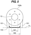
- FIG. 5 is a view showing another embodiment of the suction flange portion 100b.
- the suction flange 100b has a circular shape, and the two leg portions 151 extend downward from the bottom of the suction flange 100b.
- the distance W2 between the leg portions 151 adjacent to each other is greater than the diameter W1 of the suction port 12 (W2 > W1).
- W2 > W1 the diameter W1 of the suction port 12
- the liquid in the suction nozzle 100 flows from the volute portion 101 toward the suction port 12 and out of the suction port 12 by the action of gravity without remaining in the nozzle portion 100c.
- the drain pan 155 arranged directly below the suction flange portion 100b can receive the liquid flowing out from the suction port 12.
- the suction port 12 is the lowest bottom portion 100d of the flow path in the pump casing 5
- the bottom portion of the suction flange portion 100b is arranged at the lowest position in the pump apparatus. Therefore, as shown in FIGS. 4 and 5 , the suction flange portion 100b and the leg portion 151 can be easily used together.
- a work space WSc can be formed below the suction flange portion 100b.
- the work space WSc is a space for connecting the suction nozzle 100 to the suction pipe with the fastener 110. By forming the work space WSc, the operator can easily attach and detach the suction nozzle 100 and the suction pipe.
- FIG. 6 is a view showing another embodiment of the leg portion.
- the pump apparatus may also include a leg portion 160 connected to the intermediate bracket 50 via the pump casing 5.
- a protrusion 161 projecting outward from the cover portion 51 is formed on the cover portion 51 of the intermediate bracket 50.
- a protrusion 162 projecting outside from the pump casing 5 is formed on the pump casing 5.
- the protrusion 161 of the cover portion 51 and the protrusion 162 of the pump casing 5 are coupled to each other by fasteners (e.g., bolts) 165.
- the leg portion 160 includes a base portion 166 , a wall portion 167 extending vertically from the base portion 166, and a connection portion 168 fixed to the wall portion 167 and connectable to the protrusion 162 of the pump casing 5.
- the protrusion 162 and the connection portion 168 are connected to each other by fasteners (e.g., bolts) 170.
- the intermediate bracket 50 and the pump casing 5 are connected to each other by the fasteners 165, and the pump casing 5 and the leg portion 160 are connected to each other by fasteners 170 .
- the drain pans 155 and 156 can be arranged below the pump casing 5, and the work space WSc (see FIG. 3 ) for connecting the suction nozzle 100 to the suction pipe can be secured.
- FIG. 7 is a view showing another embodiment of the suction nozzle 100.
- the pump apparatus also includes the leg portions 150 and 151.
- the suction nozzle 100 includes a U-shaped nozzle portion 100c.
- the nozzle portion 100c has a drain port 181 at its bottom portion 180.
- the drain port 181 is a through hole for discharging the liquid inside the nozzle portion 100c to the outside. Normally, the drain port 181 is closed with a lid (not shown) during operation of the pump apparatus. When disassembling and cleaning the pump casing 5, the lid is removed and the liquid inside the pump casing 5 is drained through the drain port 181.
- the leg portions 150 and 151 form a space of the height H between the bottom portion 180 of the nozzle portion 100c and the floor FL.
- a drain pan (not shown) can be arranged directly below the drain port 181 or a drain pipe can be connected to the drain port 181.
- leg portions 150 and 151 it is possible to achieve the effect of making the pump apparatus easier to carry and the effect of being able to form the working space WSc below the suction flange portion 100b.
- the pump apparatus is a vertical pump apparatus capable of transferring the liquid (i.e., slurry liquid) containing slurry (i.e., light slurry) of about 0.05 mm.
- the impeller 3 is preferably a semi-open impeller for transferring the slurry liquid. By adopting the semi-open impeller, it is possible to suppress the slurry from being caught between the pump casing 5 and the impeller 3.
- the pump apparatus includes the impeller 3 having a larger diameter than that of a general impeller in order to obtain a large head relative to the flow rate, and rotates the rotational shaft 1 at a low speed (e.g., 1500 min -1 ).
- the suction pressure of the pump increases, and as a result, a large thrust force that pushes the impeller 3 upward (i.e., toward the cover portion 51) is generated. If the size of the gap between the impeller 3 and the cover portion 51 changes due to this thrust force, there is a risk that the pump apparatus will not be able to exhibit the desired performance, or that the slurry will be trapped to the gap between the impeller 3 and the cover portion 51. Therefore, in the embodiment described below, the pump apparatus has a structure capable of restricting the upward movement of the impeller 3 even if the large thrust force is generated.
- FIG. 8 is a view showing one embodiment of the motor 7.
- the motor 7 includes a first bearing 201A and a second bearing 201B that rotatably support the rotational shaft 1, a motor casing 203 having a first bearing support portion 202A and a second bearing support portion 202B that support the first bearing 201A and the second bearing 201B, and a bearing retainer 205 for restricting a movement of the first bearing 201A in the direction of the axis CL of the rotational shaft 1.
- the rotational shaft 1 extends through the motor casing 203, and a cooling fan 206 is fixed to an end portion 1a of the rotational shaft 1.
- the cooling fan 206 is housed in a fan cover 209 connected to the motor casing 203.
- the second bearing 201B is an anti-load side bearing arranged adjacent to the cooling fan 206.
- the first bearing 201A is a load side bearing spaced apart from the cooling fan 206.
- a rotor 210 and a stator 211 for rotating the rotational shaft 1 are arranged between the first bearing 201A and the second bearing 201B.
- the rotor 210 is fixed to the rotational shaft 1, and the stator 211 surrounds the rotor 210, and in the stator 211, a winding (coil) 211b receives the electric power to form a rotating magnetic field.
- the stator 211 includes a stator core 211a, and a plurality of windings 211b wound around the stator core 211a.
- the rotor 210 is rotated by the rotating magnetic field formed between the rotor 210 and the stator 211, and the rotational shaft 1 to which the rotor 210 is fixed rotates together with the rotor 210.
- the first bearing 201A is supported by the first bearing support portion 202A
- the second bearing 201B is supported by the second bearing support portion 202B.
- the motor 7 includes the bearing retainer 205 that receives the thrust force acting on the first bearing 201A.
- FIG. 9 is a view showing the bearing retainer 205.
- the bearing retainer 205 is fixed to the first bearing support portion 202A by a plurality of fasteners 212.
- the bearing retainer 205 has an annular shape, and is arranged concentrically with the rotational shaft 1.
- the fasteners 212 are preferably arranged at regular intervals along the circumferential direction of the bearing retainer 205.
- the bearing retainer 205 has a through hole 207 into which the fastener 212 can be inserted.
- the first bearing support portion 202A has a fastening hole 208 into which the fastener 212 can be inserted. By inserting the fastener 212 into the through hole 207 and the fastening hole 208 and tightening the fastener 212, the bearing retainer 205 is fixed to the first bearing support portion 202A.
- the bearing retainer 205 can reliably receive the thrust force acting on the first bearing 201A. Therefore, the pump apparatus can maintain a desired size of the gap between the impeller 3 and the cover portion 51 even if a large upward thrust force is generated in the impeller 3.
- the pump apparatus is capable of pumping the slurry liquid, including the light slurry. If the slurry liquid is continuously transferred, the components (the impeller 3, the pump casing 5, and the cover portion 51, etc.) of the pump apparatus that come into contact with the slurry liquid may be worn. This wear changes the size of the gap between the impeller 3 and its peripheral members (e.g., the pump casing 5 and the cover portion 51), which may adversely affect the performance of the pump apparatus. Furthermore, the pump apparatus is capable of transferring hot liquids to be handled. In this case, the components of the pump apparatus thermally expand under the influence of the heat of the liquid to be handled, and as a result, there is a risk that the size of the gap between the impeller 3 and its peripheral members will change. Therefore, in the embodiments described below, the pump apparatus includes a gap adjustment structure for adjusting the size of the gap.
- FIG. 10 is a view showing the gap adjustment structure.
- peripheral members of the impeller 3 e.g., the pump casing 5 and the cover portion 51
- the pump apparatus includes the impeller housing structure 300 housing the impeller 3, and a gap adjustment structure 305 for adjusting the size of the gap between the impeller 3 and the impeller housing structure 300.
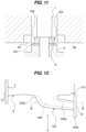
- FIG. 11 is an enlarged view of the gap adjustment structure 305.
- the gap adjustment structure 305 includes a distance piece 306 attached to a stepped portion 1b of the rotational shaft 1, and at least one shim 307 arranged between the distance piece 306 and the impeller 3.
- Each of the distance piece 306 and the shim 307 has an annular shape, and is arranged concentrically with rotational shaft 1.
- the shim 307 has a minute thickness (e.g., 0.1 mm). The operator adjusts the size of the gap between the impeller 3 and the impeller housing structure 300 by arranging one or more shims 307 with the distance piece 306 attached.
- the operator When transferring a high-temperature liquid to be handled, the operator considers the thermal expansion of the impeller 3 and the impeller housing structure 300, and determines the number of shims 307 to be arranged.
- the size of the gap between the impeller 3 and the impeller housing structure 300 can be freely adjusted by a simple method of adjusting the number of shims 307.
- the pump apparatus has a structure in which the impeller 3 is directly fixed to the rotational shaft 1 extending from the motor 7. Therefore, it is particularly effective to provide the gap adjustment structure 305 that allows the gap to be adjusted without requiring a complex structure.
- the operator adds the shim 307 during maintenance of the pump apparatus.
- the size of the gap between the impeller 3 and the impeller housing structure 300 can be adjusted to an appropriate size. Therefore, the cost of the pump apparatus can be reduced.
- the pump apparatus does not need to have a special structure for transferring the slurry liquid by including the gap adjustment structure 305, and can also transfer the liquid to be handled such as clean water. More specifically, the operator may remove the gap adjustment structure 305 when transferring the liquid to be handled such as clear water, and may attach the gap adjustment structure 305 when transferring the slurry liquid.
- FIG. 12 is a view showing another embodiment of the pump apparatus.
- the suction nozzle 100 slopes downward from the volute portion 101 toward the suction port 12.
- a length of the suction nozzle 100 extending outward from the volute portion 101 can be shortened, and as a result, the overall size of the pump apparatus can be made compact (see FIG. 2 ).
- the size of the suction nozzle 100 in the height direction is reduced, and the width direction (more specifically, a direction from the centerline CL of the pump apparatus to the suction flange 100b) of the suction nozzle 100 is desirable. Also, it is important to minimize the change in the shape of the suction nozzle 100 and increase a cross-sectional area (cross-sectional area in the height direction) of the flow path of the suction nozzle 100 at a constant rate of change. This is because the pump casing 5 generally causes problems such as cavitation when the flow rate on the suction side is largely throttled. Therefore, it is desirable that the suction nozzle 100 has a shape that suppresses pressure loss while ensuring a predetermined cross-sectional area in the flow path.
- FIG. 13 is a cross-sectional view taken along a line B-B of FIG. 12 .
- FIG. 14 is a view seen from a direction of a line C in FIG. 12 .
- the suction nozzle 100 has a flow path 400 that slopes downward from the volute portion 101 (more specifically, a connection portion 100a connected to the volute portion 101) toward the suction port 12, and a wide portion 100d arranged between the suction port 12 and the connection portion 100a so that the cross-sectional area of the flow path 400 increases at a constant rate of change from the suction port 12 toward the connection portion 100a.
- the wide portion 100d extends horizontally in order to reduce the size of the suction nozzle 100 in the height direction, and realize a compact pump apparatus.
- the flow rate of the liquid to be handled in the wide portion 100d increases. Therefore, by providing the wide portion 100d, the suction nozzle 100 can increase the cross-sectional area of the flow path 400 at a constant rate of change. As a result, the pump apparatus can ensure the necessary flow rate while preventing cavitation from occurring.
- the suction nozzle 100 can be tilted at an optimum angle to reduce pressure loss.
- FIG. 15 is a view showing another embodiment of the pump casing.
- the pump casing 5 may have a drain structure. More specifically, the volute portion 101 of the pump casing 5 has the volute chamber 102 in which the impeller 3 is housed.
- the volute chamber 102 has a bottom surface 102a arranged below the impeller 3, and an outer peripheral portion 102b arranged outside the impeller 3.
- the bottom surface 102a of the volute chamber 102 slopes downward from the outer peripheral portion 102b of the volute chamber 102 toward the connection portion 100a.
- the liquid to be handled that remains in the volute chamber 102 after stopping the operation of the pump apparatus flows down the bottom surface 102a due to the action of gravity, and is smoothly discharged from the volute chamber 102.
- the suction nozzle 100 is sloped downward toward the suction portion 12. Therefore, the liquid to be handled discharged from the volute chamber 102 flows down the nozzle portion 100c, which extends diagonally downward from the connection portion 100a to the suction flange portion 100b, and is smoothly discharged from the suction port 12.
- the suction port 12 is arranged at a position lower than the discharge port 13, and is arranged on the side of the suction flange portion 100b. Therefore, the liquid to be handled remaining in the volute chamber 102 is reliably directed to the suction nozzle 100 without flowing to the discharge port 13 side.
- drain structure applied to the pump casing 5 according to the embodiment shown in FIG. 1 has been described in the embodiment shown in FIG. 15 , such a drain structure can also be applied to the pump casing 5 according to the embodiment shown in FIG. 12 .
- the present invention is applicable to a pump casing and a pump apparatus.
Landscapes
- Engineering & Computer Science (AREA)
- Mechanical Engineering (AREA)
- General Engineering & Computer Science (AREA)
- Structures Of Non-Positive Displacement Pumps (AREA)
Abstract
Description
- The present invention relates to a pump casing and a pump apparatus.
- A pump apparatus is known that includes a rotational shaft, an impeller fixed to the rotational shaft, a motor that rotates the impeller together with the rotational shaft, and a pump casing having a suction port and a discharge port and housing the impeller (see for example Patent Document 1).
- When the motor is driven, the rotational shaft and impeller rotate. When the impeller rotates, a liquid flows through the suction port into the pump casing and is pressurized as the impeller rotates. The pressurized liquid is discharged from the discharge port.
-
- Patent document 1:
Japanese laid-open patent publication No. 2017-96374 - Patent document 2:
Japanese laid-open patent publication No. 2017-89839 - Depending on the intended use, the pump apparatus is periodically disassembled and cleaned in order to maintain the quality of the liquid to be conveyed. When the pump is removed from a pipe and an inside of the pump casing is cleaned, it is necessary to completely remove a liquid remaining in the pump casing. When the removed pump is moved, there is a concern that the liquid remaining in the pump casing will contaminate the surroundings.
- It is therefore an object of the present invention to provide a pump casing and a pump apparatus including the pump casing, which have a simple structure and can be easily cleaned in an internal flow path.
- In an embodiment, there is provided a pump casing having a suction port connected to a horizontally extending suction pipe, comprising: a suction nozzle with formed the suction port, and the suction nozzle sloping downward toward the suction port.
- In an embodiment, the suction port is a bottom portion in the pump casing.
- In an embodiment, the pump casing comprises a volute portion connecting to the suction nozzle, and the suction nozzle has a straight shape extending diagonally downward from the volute portion.
- In an embodiment, the suction port is arranged below the volute portion, and a work space for connecting the suction nozzle to the suction pipe is formed between the volute portion and the suction nozzle.
- In an embodiment, there is provided a pump casing having a suction port and a discharge port, comprising: a suction nozzle with formed the suction port, and the suction nozzle having a drain port at a bottom portion of the suction nozzle.
- In an embodiment, there is provided a pump apparatus comprising: an impeller; a rotational shaft fixing to the impeller; a motor configured to rotate the rotational shaft; and a pump casing according to above described, the pump casing housing the impeller.
- In an embodiment, the pump apparatus comprising a leg portion connected to the pump casing.
- In an embodiment, the leg portion forms a space below a suction flange portion having the suction port, the space arranging a drain pan configured to catch a liquid discharged from the suction port.
- In an embodiment, the pump casing comprises a suction nozzle with formed the suction port, the suction nozzle has a drain port at a bottom portion of the suction nozzle, and the leg portion forms a space below the drain port, the space arranging a drain pan configured to catch the liquid discharged from the suction port.
- In an embodiment, the pump casing comprises a suction nozzle with formed the suction port, the suction nozzle has a drain port at a bottom portion of the suction nozzle, and the leg portion forms a space arranging a pipe connectable to the drain port.
- In an embodiment, there is provided a pump apparatus comprising: an impeller; a rotational shaft fixing to the impeller; a motor configured to rotate the rotational shaft; and a pump casing housing the impeller, the motor comprises: a bearing configured to rotatably support the rotational shaft; a motor casing having a bearing support portion configured to support the bearing; and a bearing retainer configured to restrict a movement of the bearing in an axial direction of the rotational shaft.
- In an embodiment, the bearing retainer is fixed to the bearing support portion.
- In an embodiment, the bearing retainer has an annular shape.
- In an embodiment, the pump apparatus is a vertical pump apparatus.
- In an embodiment, there is provided a vertical pump apparatus comprising: an impeller; a rotational shaft fixing to the impeller; an impeller housing structure configured to house the impeller; and a gap adjustment structure configured to adjust a size of a gap between the impeller and the impeller housing structure.
- In an embodiment, the gap adjustment structure comprises: a distance piece attached to a stepped portion of the rotational shaft; and at least one shim arranged between the distance piece and the impeller.
- In an embodiment, there is provided a pump casing comprising: a suction nozzle having a suction port; and a volute portion connecting to the suction nozzle, and the suction nozzle slopes downward from a connection portion connected to the volute portion toward the suction port, and has a flow path whose cross-sectional area increases from the suction port to the connection portion.
- In an embodiment, the suction nozzle has a wide portion arranged between the suction port and the connection portion.
- In an embodiment, the wide portion extends horizontally.
- In an embodiment, a cross-sectional area of the flow path increases at a constant rate of change from the suction port toward the connection portion.
- In an embodiment, there is provided a pump casing comprising: a suction nozzle having a suction port; and a volute portion connected to a connection portion of the suction nozzle, and the volute portion having a volute chamber, a bottom surface of the volute chamber slopes downward from a peripheral portion of the volute chamber toward the connection portion.
- In an embodiment, the suction nozzle slopes downward from the connection portion toward the suction port.
- In an embodiment, the suction port is arranged at a position lower than a discharge port of the pump casing.
- The pump casing includes a suction nozzle that can discharge an inside liquid at the bottom portion of the flow path of the pump casing. Therefore, the liquid in the pump casing is discharged outside from the suction nozzle by the action of gravity.
-
- [
FIG. 1] FIG. 1 is a view showing one embodiment of a pump apparatus; - [
FIG. 2] FIG. 2 is a view for explaining an effect of a pump casing including a suction nozzle; - [
FIG. 3] FIG. 3 is a view showing another embodiment of the pump apparatus; - [
FIG. 4] FIG. 4 is a view seen from a direction of a line A inFIG. 3 ; - [
FIG. 5] FIG. 5 is a view showing another embodiment of a suction flange portion; - [
FIG. 6] FIG. 6 is a view showing another embodiment of the leg portion; - [
FIG. 7] FIG. 7 is a view showing another embodiment of the suction nozzle; - [
FIG. 8] FIG. 8 is a view showing one embodiment of a motor; - [
FIG. 9] FIG. 9 is a view showing a bearing retainer; - [
FIG. 10] FIG. 10 is a view showing a gap adjustment structure; - [
FIG. 11] FIG. 11 is an enlarged view of the gap adjustment structure; - [
FIG. 12] FIG. 12 is a view showing another embodiment of the pump apparatus; - [
FIG. 13] FIG. 13 is a cross-sectional view taken along a line B-B ofFIG. 12 ; - [
FIG. 14] FIG. 14 is a view seen from a direction of a line C inFIG. 12 ; and - [
FIG. 15] FIG. 15 is a view showing another embodiment of the pump casing. - Embodiments of the present invention will be described with reference to the drawings.
FIG. 1 is a view showing one embodiment of a pump apparatus. As shown inFIG. 1 , the pump apparatus includes arotational shaft 1 for pressurizing a liquid to be handled (transferred liquid), animpeller 3 fixed to therotational shaft 1, apump casing 5 housing theimpeller 3, amotor 7 for rotating therotational shaft 1, anintermediate bracket 50 arranged between thepump casing 5 and themotor 7, and ashaft sealing device 30 for preventing leakage of high-pressure liquid. Thepump casing 5 includes asuction port 12 and adischarge port 13, and is made of a corrosion-resistant material (e.g., stainless steel). In the embodiment shown inFIG. 1 , therotational shaft 1 is arranged vertically (see a direction of an axis line CL inFIG. 1 ). Theintermediate bracket 50 has an opening 50a through which therotational shaft 1 penetrates, and theshaft sealing device 30 seals the transferred liquid leaking to the outside (i.e., the outside is the motor 7) from the opening 50a through which therotational shaft 1 penetrates. - When the
motor 7 is driven, a rotation of themotor 7 is transmitted to therotational shaft 1, and therotational shaft 1 and theimpeller 3 rotate. When theimpeller 3 rotates, the liquid flows into thepump casing 5 through thesuction port 12, and is pressurized as theimpeller 3 rotates. The pressurized liquid is discharged from thedischarge port 13. In the embodiment shown inFIG. 1 , theimpeller 3 is a semi-open impeller. In one embodiment, theimpeller 3 may be a vortex impeller or a closed impeller. - The
shaft sealing device 30 is a device that seals a gap between therotational shaft 1 and theintermediate bracket 50. An example of theshaft sealing device 30 includes a double mechanical seal. Theshaft sealing device 30 includes a rotary side seal member (not shown) fixed to therotational shaft 1, and a stationary side seal member (not shown) fixed to theintermediate bracket 50. Therefore, when therotational shaft 1 rotates, the rotary side seal member comes into sliding contact with the stationary side seal member, and theshaft sealing device 30 generates heat. - Further, in such pump apparatus, the temperature of the liquid to be handled may range from low temperature (e.g., -25°C) to high temperature (e.g., 140°C). For example, when the temperature of the liquid to be handled is higher than an allowable temperature of the
shaft sealing device 30, if the hot liquid to be handled directly contacts theshaft sealing device 30, the temperature of theshaft sealing device 30 generated by the sliding heat rises further. In this embodiment, the liquid to be handled includes a slurry liquid containing a slurry of about 0.05 mm. In one embodiment, the liquid to be handled may include clean water or dirty water. - In this manner, the
shaft sealing device 30 becomes very hot due to the sliding of the rotary side seal member and the stationary side seal member, and contact with the high-temperature liquid to be handled, and theshaft sealing device 30 may fail. As a result, theshaft sealing device 30 cannot fully exhibit its function, and the liquid may leak to themotor 7 side, and themotor 7 may be submerged in water. Therefore, in the pump apparatus, a structure capable of reliably preventing failure of theshaft sealing device 30 is desired. - The pump apparatus includes a normal
temperature flow path 60 that keeps the liquid flowing through theshaft sealing device 30 within a predetermined temperature range. In other words, the pump apparatus includes the normal temperature flow path 60 (second flow path) that keeps the liquid to be handled in theflow path 90 within a predetermined temperature range. Theopening 50a forms the flow path 90 (first flow path) through which the liquid to be handled flows into theshaft sealing device 30. In the embodiment, the normaltemperature flow path 60 is formed in theintermediate bracket 50. More specifically, theintermediate bracket 50 includes acover portion 51 covering anopening end 5a of thepump casing 5, and abracket portion 52 connected to thecover portion 51. The normaltemperature flow path 60 is formed in at least one of thecover portion 51 and thebracket portion 52. - The normal
temperature flow path 60 is formed in both thecover portion 51 and thebracket portion 52, but in one embodiment, the normaltemperature flow path 60 may be formed only in thecover portion 51, or may be formed in thebracket portion 52. That is, theopening 50a is formed at anopening 51a in thecover portion 51 through which therotational shaft 1 passes and/or theopening 52a in thebracket portion 52 through which therotational shaft 1 passes. Theopening 50a forms theflow path 90, and thenormal temperature channel 60 is formed adjacent to at least a portion of theopening 50a so that the liquid to be handled in theflow path 90 can be kept within a predetermined temperature range. Theshaft sealing device 30 determines an allowable temperature range according to its product specifications. The predetermined temperature range described as "the liquid to be handled in theflow path 90 can be kept within a predetermined temperature range" means that the temperature of theshaft sealing device 30 is within the allowable range even if theshaft sealing device 30 generates heat due to sliding. - The normal
temperature flow path 60 is arranged radially outward of theflow path 90 formed by an outer peripheral surface of therotational shaft 1 and an inner peripheral surface (opening 50a) of theintermediate bracket 50. The liquid to be handled pressurized by the rotation of theimpeller 3 contacts theshaft sealing device 30 after being heat-exchanged by the fluid in the normaltemperature flow path 60 separated by aside wall 60a when flowing through theflow path 90. In other words, the liquid to be handled in theflow path 90 that has been brought to an appropriate temperature by the fluid in the normaltemperature flow path 60 can be used for lubricating theshaft sealing device 30. Therefore, theshaft sealing device 30 can prevent leakage to themotor 7 side even if the liquid to be handled is out of the allowable range. - The normal
temperature flow path 60 communicates with aliquid inlet 61 and aliquid outlet 62. The liquid (e.g., tap water) flows from a liquid supply source (not shown) through theliquid inlet 61 into the normaltemperature flow path 60. The normal temperature liquid (e.g., clear water of 0°C to 65°C) that has flowed into the normaltemperature flow path 60 keeps the temperature of the liquid present in theflow path 90 arranged radially inside the normaltemperature flow path 60 within a predetermined range (e.g., 0°C to 65°C). - For example, when the temperature of the liquid to be handled is higher than the allowable range of the shaft sealing device 30 (e.g., 140°C), the high-temperature liquid to be handled is cold by the liquid flowing through the normal temperature flow path 60 (e.g., tap water or industrial water of the normal temperature of 0°C to 35°C). Conversely, when the temperature of the liquid to be handled is lower than the allowable range of the shaft sealing device 30 (e.g., minus 25°C), the low-temperature liquid to be handled is heated by the liquid flowing through the normal flow path 60 (e.g., tap water or industrial water of the normal temperature of 0°C to 35°C). Thereby, the temperature of the
shaft sealing device 30 can be kept within the allowable range. After that, the liquid that has flowed into the normaltemperature flow path 60 is discharged from theliquid outlet 62. The liquid flowing through the normaltemperature flow path 60 is an example of a fluid, and examples of the fluid may be tap water, factory water, or gas. - In this manner, clean water (tap water, factory pumped water, etc.), which is easy to handle, is used as a fluid for keeping the temperature of the
shaft sealing device 30 within the allowable range while avoiding theshaft sealing device 30 from coming into contact with the liquid to be handled whose temperature is outside the allowable range. In the embodiment, the fluid in the normaltemperature flow path 60 used for adjusting the temperature of theshaft sealing device 30 does not mix with the liquid to be handled pressurized by theimpeller 3. Therefore, the temperature of theshaft sealing device 30 can be kept within the allowable range by using a fluid different from the liquid to be handled. In other words, a user can select the fluid for the normaltemperature flow path 60 depending on an equipment and an environment. Therefore, the pump apparatus of this embodiment is particularly effective when the transferred liquid is a special liquid containing slurry or the like. - Further, it is preferable that the
intermediate bracket 50 includes athrottle portion 65 that throttles the flow path of the liquid (i.e., the liquid to be handled) flowing through theshaft sealing device 30. Thethrottle portion 65 shown inFIG. 1 is a member (e.g., a bush) having an annular shape. Thethrottle portion 65 is fixed to the inner peripheral surface of thecover portion 51 which is the inlet of theflow path 90, and arranged concentrically with therotational shaft 1. Thethrottle portion 65 reduces a flow rate of the liquid to be handled through theflow path 90 by reducing the flow path 90 (i.e., the gap between thethrottle portion 65 and the impeller 3) to theshaft sealing device 30. As a result, the time for heat exchange with the fluid in the roomtemperature flow path 60 is lengthened, and a cooling effect can be expected. - Furthermore, it is preferable that a retaining
chamber 66 for liquid flowing to theshaft sealing device 30 is formed between theshaft sealing device 30 and thethrottle portion 65. The retainingchamber 66 is an annular chamber formed between an outer peripheral surface of therotational shaft 1 and the inner peripheral surface of thecover portion 51, and the liquid that has passed through the gap between thethrottle portion 65 and theimpeller 3 retains in the retainingchamber 66. - During an initial operation of the pump apparatus, the liquid to be handled that has flowed into the
pump casing 5 due to the rotation of theimpeller 3 passes through the small gap between theimpeller 3 and thethrottle portion 65, and flows into the retainingchamber 66. The liquid once flowing into the retainingchamber 66 continues to stay in the retainingchamber 66 until the pressure inside thepump casing 5 is sufficiently lowered. - The normal
temperature flow path 60 is arranged outside the retainingchamber 66, and the retainingchamber 66 communicates with theshaft sealing device 30. More specifically, the normaltemperature flow path 60 is an annular flow path surrounding the retainingchamber 66. Therefore, the liquid existing in the retainingchamber 66 is more actively heat-exchanged with the liquid flowing through the normaltemperature flow path 60. - In this manner, the liquid in contact with the
shaft sealing device 30 is retained in the retainingchamber 66 for a long time, and heat is exchanged with the liquid flowing through the normaltemperature flow path 60. The temperature of theshaft sealing device 30 falls within the allowable range. That is, the liquid to be handled within a predetermined temperature range that allows the temperature of theshaft sealing device 30 to remain in the retainingchamber 66, and the liquid retained in the retainingchamber 66 is used to lubricate theshaft sealing device 30. With such a configuration, the liquid existing in the retainingchamber 66 prevents the contact of the high-temperature or low-temperature liquid outside the predetermined temperature range with theshaft sealing device 30. As a result, theshaft sealing device 30 can be prevented from failing due to contact with the high-temperature or low-temperature liquid. - In this embodiment, the pump apparatus includes the normal
temperature flow path 60 that keeps the liquid flowing through theshaft sealing device 30 within a predetermined temperature range, but means for protecting theshaft sealing device 30 is not limited to this embodiment. In one embodiment, the pump apparatus does not need to include at least one of the normaltemperature flow path 60, thethrottle portion 65, the retainingchamber 66, etc., as long as theshaft sealing device 30 can be protected. - As described above, the pump apparatus is periodically disassembled and cleaned depending on the intended use. During this disassembly and cleaning, it is necessary to completely remove the liquid inside the pump apparatus. However, since an internal flow path of the
pump casing 5 has a complicated shape, it is troublesome to remove the remaining liquid. - In particular, in the pump apparatus according to the present embodiment, a slurry liquid is included as the liquid to be handled, and the slurry liquid tends to remain in the
pump casing 5 when disassembly and cleaning of the pump apparatus. Therefore, in the embodiment described below, the structure of thepump casing 5, which has a simple structure and can be easily washed, will be described with reference to the drawings. - The
pump casing 5 has asuction nozzle 100 with thesuction port 12 formed therein. In the pump apparatus, thesuction port 12 is flange-connected to a horizontally extending a suction pipe S, and thedischarge port 13 is flange-connected to a horizontally extending a discharge pipe D by fasteners (e.g., bolts and nuts). The pump apparatus is operated in that state. Thesuction nozzle 100 slopes downward toward thesuction port 12. More specifically, thepump casing 5 further includes avolute portion 101 to which thesuction nozzle 100 is connected, and thesuction nozzle 100 slopes downward from thevolute portion 101 toward thesuction port 12. - The
volute portion 101 forms avolute chamber 102 around theimpeller 3 housed in thepump casing 5. The transferred liquid pressurized by theimpeller 3 in thevolute chamber 102 is discharged from thedischarge port 13 laterally extending from thevolute chamber 102. Thesuction nozzle 100 is connected to the center of a bottom of thevolute portion 101, and extends downward from thevolute portion 101. - The
suction nozzle 100 includes aconnection portion 100a connected to thevolute portion 101, asuction flange portion 100b having thesuction port 12, and anozzle portion 100c connected to theconnection portion 100a and thesuction flange portion 100b. Thenozzle portion 100c extends obliquely downward from theconnection portion 100a toward thesuction flange portion 100b, and thesuction port 12 of thesuction nozzle 100 is arranged below theconnection portion 100a of thesuction nozzle 100. That is, thesuction port 12 is a bottom portion of the flow path inside thepump casing 5. - Therefore, when the operator stops the pump apparatus, and removes the
suction nozzle 100 from the suction pipe S, the liquid in thesuction nozzle 100 does not remain in thenozzle portion 100c as indicated by the arrow inFIG. 1 , smoothly flows from the flow path on the discharge side of theimpeller 3 and thevolute portion 101 toward thesuction port 12. As a result, when the pump apparatus is disassembled and cleaned, the liquid in thepump casing 5 flows through the downwardlyinclined suction nozzle 100, and is discharged to the outside through thesuction port 12 without requiring special work. - In this manner, the pump apparatus of this embodiment has a simple structure in which the
suction nozzle 100 extends obliquely downward. The pump apparatus can cause the liquid to flow out of thepump casing 5 when the suction-side pipe (suction pipe S) is removed. With such a structure, a drain work for removing the liquid from thepump casing 5 can be simplified, and the operator can disassemble and clean the pump apparatus without much trouble. -
FIG. 2 is a view for explaining an effect of thepump casing 5 including thesuction nozzle 100.FIG. 2 shows a suction nozzle 100 (see a lower drawing inFIG. 2 ) according to the embodiment shown inFIG. 1 and a conventional suction nozzle 1000 (see an upper drawing inFIG. 2 ) as a comparative example. - As shown in the upper drawing of
FIG. 2 , theconventional suction nozzle 1000 includes aconnection portion 1000a connected to thevolute portion 101, and asuction flange portion 1000b having thesuction port 12 that is approximately the same height as thedischarge port 13, and aU-shaped nozzle portion 1000c connected to theportion 1000a and thesuction flange portion 1000b. That is, in theconventional suction nozzle 1000, thesuction port 12 and thedischarge port 13 have substantially the same height. Therefore, thenozzle portion 1000c extending obliquely downward from theconnection portion 1000a is curved obliquely upward, alowest bottom portion 1000d within thepump casing 5 is formed in the curved portion. - Therefore, when the
suction flange portion 1000b is removed from the suction pipe S, the liquid inside thepump casing 5 may remain on thebottom portion 1000d. In other words, in order to completely remove the liquid in thepump casing 5 at thesuction nozzle 1000 shown in the comparative example, it is necessary for the operator to perform the draining work shown in the example below. - (1) Draining work for blowing off the liquid remaining at the bottom 1000d by jetting high-pressure gas.
- (2) Draining work by tilting the
pump casing 5 and lowering thesuction port 12 below thebottom 1000d. - (3) Draining work using another device (e.g., pump apparatus, tool, etc.).
- In the embodiment, the
nozzle portion 100c has a linear shape extending obliquely downward from theconnection portion 1000a, so that thesuction port 12 is alowest bottom portion 100d of the flow path in thepump casing 5. Therefore, when the suction pipe S is removed from thesuction flange portion 100b, the liquid in thepump casing 5 is discharged outside through thesuction port 12, which is thebottom portion 100d, by the action of gravity, and hardly remains in thenozzle portion 100c. As a result, the above-described draining work can be omitted, and a cleaning work in thepump casing 5 can be simplified. - In the embodiment of lower side of
FIG. 2 , the suction nozzle 100 (more specifically, thenozzle portion 100c) extends obliquely downward in a straight line from theconnection portion 100a to thesuction port 12. Therefore, the operator can easily see the inside of thesuction nozzle 100 through thesuction port 12. As a result, the operator can easily inspect the inside of the suction nozzle 100 (e.g., whether there is residue). - In the comparative example, the upper portion of the
suction flange portion 1000b is arranged side by side with thevolute portion 101. Therefore, thesuction nozzle 1000 extends outward such that a working space WSa is formed between thevolute portion 101 and thesuction flange portion 1000b. The work space WSa is a space necessary for a work of a flange-connecting the pump apparatus and the suction pipe S by means of a fastener (e.g., a bolt and nut combination) 110. - Since the
suction flange portion 100b of thesuction nozzle 100 of the embodiment is arranged at a position lower than thevolute portion 101, the work space WSa can be formed between thevolute portion 101 and thenozzle portion 100c. - In the
suction nozzle 100, the work space WSa can be secured below thevolute portion 101 as well. With such a structure, a distance D1 between a center line CL of the pump apparatus and thesuction flange portion 100b can be made smaller by a difference DS than a distance D2 between the center line CL of the pump apparatus and thesuction flange portion 1000b. In this embodiment, the length of thesuction nozzle 100 extending outward from thevolute portion 101 can be shortened as compared with the comparative example. Therefore, the pump apparatus including thesuction nozzle 100 according to the embodiment can be compact in overall size. -
FIG. 3 is a view showing another embodiment of the pump apparatus. In the embodiment shown inFIG. 3 the pump apparatus includesleg portions pump casing 5. By providing theleg portions - Furthermore, it is preferable that the
leg portions suction flange portion 100b and the floor FL. By forming the space of the height H, adrain pan 155 for collecting waste liquid can be arranged directly below thesuction flange portion 100b. As shown inFIG. 3 , adrain pan 156 may be arranged directly below thedischarge port 13. It is possible to easily collect a waste liquid that flows out when the pipe is removed. -
FIG. 4 is a view seen from a direction of a line A inFIG. 3 . InFIG. 4 , thesuction flange portion 100b has a ground plane, and the twoleg portions 151 are formed at the ground plane of thesuction flange portion 100b. Thesuction flange portion 100b and theleg portion 151 are integrally molded member. Thedrain pan 155 is arranged between twoleg portions 151 adjacent to each other. In the embodiment, thesuction flange portion 100b is not limited to the shape shown in the drawing as long as it has a ground surface. Any shape may be used as long as it can be flange-connected to the suction pipe S. -
FIG. 5 is a view showing another embodiment of thesuction flange portion 100b. In the embodiment shown inFIG. 5 , thesuction flange 100b has a circular shape, and the twoleg portions 151 extend downward from the bottom of thesuction flange 100b. As shown inFIG. 5 , in order to arrange thedrain pan 155 below thesuction port 12, the distance W2 between theleg portions 151 adjacent to each other is greater than the diameter W1 of the suction port 12 (W2 > W1). With such a configuration, thedrain pan 155 is arranged below thesuction port 12, and the twoleg portions 151 are arranged on both sides of thedrain pan 155. - By removing the suction pipe from the
suction nozzle 100, the liquid in thesuction nozzle 100 flows from thevolute portion 101 toward thesuction port 12 and out of thesuction port 12 by the action of gravity without remaining in thenozzle portion 100c. Thedrain pan 155 arranged directly below thesuction flange portion 100b can receive the liquid flowing out from thesuction port 12. - Since the
suction port 12 is thelowest bottom portion 100d of the flow path in thepump casing 5, the bottom portion of thesuction flange portion 100b is arranged at the lowest position in the pump apparatus. Therefore, as shown inFIGS. 4 and5 , thesuction flange portion 100b and theleg portion 151 can be easily used together. By providing theleg portions suction flange portion 100b. The work space WSc is a space for connecting thesuction nozzle 100 to the suction pipe with thefastener 110. By forming the work space WSc, the operator can easily attach and detach thesuction nozzle 100 and the suction pipe. -
FIG. 6 is a view showing another embodiment of the leg portion. As shown inFIG. 6 , instead of theleg portions leg portion 160 connected to theintermediate bracket 50 via thepump casing 5. In the embodiment shown inFIG. 6 , aprotrusion 161 projecting outward from thecover portion 51 is formed on thecover portion 51 of theintermediate bracket 50. Similarly, aprotrusion 162 projecting outside from thepump casing 5 is formed on thepump casing 5. Theprotrusion 161 of thecover portion 51 and theprotrusion 162 of thepump casing 5 are coupled to each other by fasteners (e.g., bolts) 165. - The
leg portion 160 includes abase portion 166 , awall portion 167 extending vertically from thebase portion 166, and aconnection portion 168 fixed to thewall portion 167 and connectable to theprotrusion 162 of thepump casing 5. Theprotrusion 162 and theconnection portion 168 are connected to each other by fasteners (e.g., bolts) 170. - With such a configuration, the
intermediate bracket 50 and thepump casing 5 are connected to each other by thefasteners 165, and thepump casing 5 and theleg portion 160 are connected to each other byfasteners 170 . Also in the embodiment shown inFIG. 6 , by providing theleg portion 160, the drain pans 155 and 156 (seeFIG. 3 ) can be arranged below thepump casing 5, and the work space WSc (seeFIG. 3 ) for connecting thesuction nozzle 100 to the suction pipe can be secured. -
FIG. 7 is a view showing another embodiment of thesuction nozzle 100. In the embodiment shown inFIG. 7 , the pump apparatus also includes theleg portions FIG. 7 , thesuction nozzle 100 includes aU-shaped nozzle portion 100c. As shown inFIG. 7 , thenozzle portion 100c has adrain port 181 at itsbottom portion 180. Thedrain port 181 is a through hole for discharging the liquid inside thenozzle portion 100c to the outside. Normally, thedrain port 181 is closed with a lid (not shown) during operation of the pump apparatus. When disassembling and cleaning thepump casing 5, the lid is removed and the liquid inside thepump casing 5 is drained through thedrain port 181. - In the embodiment shown in
FIG. 7 , theleg portions bottom portion 180 of thenozzle portion 100c and the floor FL. By forming a space of the height H, when the liquid is discharged, a drain pan (not shown) can be arranged directly below thedrain port 181 or a drain pipe can be connected to thedrain port 181. - Furthermore, by providing the
leg portions suction flange portion 100b. - The pump apparatus according to the embodiment described above is a vertical pump apparatus capable of transferring the liquid (i.e., slurry liquid) containing slurry (i.e., light slurry) of about 0.05 mm. The
impeller 3 is preferably a semi-open impeller for transferring the slurry liquid. By adopting the semi-open impeller, it is possible to suppress the slurry from being caught between thepump casing 5 and theimpeller 3. Furthermore, the pump apparatus includes theimpeller 3 having a larger diameter than that of a general impeller in order to obtain a large head relative to the flow rate, and rotates therotational shaft 1 at a low speed (e.g., 1500 min-1). - With such a structure, the suction pressure of the pump increases, and as a result, a large thrust force that pushes the
impeller 3 upward (i.e., toward the cover portion 51) is generated. If the size of the gap between theimpeller 3 and thecover portion 51 changes due to this thrust force, there is a risk that the pump apparatus will not be able to exhibit the desired performance, or that the slurry will be trapped to the gap between theimpeller 3 and thecover portion 51. Therefore, in the embodiment described below, the pump apparatus has a structure capable of restricting the upward movement of theimpeller 3 even if the large thrust force is generated. -
FIG. 8 is a view showing one embodiment of themotor 7. As shown inFIG. 8 , themotor 7 includes afirst bearing 201A and asecond bearing 201B that rotatably support therotational shaft 1, amotor casing 203 having a firstbearing support portion 202A and a secondbearing support portion 202B that support thefirst bearing 201A and thesecond bearing 201B, and a bearingretainer 205 for restricting a movement of thefirst bearing 201A in the direction of the axis CL of therotational shaft 1. - The
rotational shaft 1 extends through themotor casing 203, and a coolingfan 206 is fixed to anend portion 1a of therotational shaft 1. The coolingfan 206 is housed in afan cover 209 connected to themotor casing 203. Thesecond bearing 201B is an anti-load side bearing arranged adjacent to the coolingfan 206. Thefirst bearing 201A is a load side bearing spaced apart from the coolingfan 206. - A
rotor 210 and astator 211 for rotating therotational shaft 1 are arranged between thefirst bearing 201A and thesecond bearing 201B. Therotor 210 is fixed to therotational shaft 1, and thestator 211 surrounds therotor 210, and in thestator 211, a winding (coil) 211b receives the electric power to form a rotating magnetic field. Thestator 211 includes astator core 211a, and a plurality ofwindings 211b wound around thestator core 211a. Therotor 210 is rotated by the rotating magnetic field formed between therotor 210 and thestator 211, and therotational shaft 1 to which therotor 210 is fixed rotates together with therotor 210. - The
first bearing 201A is supported by the firstbearing support portion 202A, and thesecond bearing 201B is supported by the secondbearing support portion 202B. As described above, when the thrust force that pushes up theimpeller 3 is generated, the thrust force acts on thefirst bearing 201A and thesecond bearing 201B through therotational shaft 1. The thrust force acting on thesecond bearing 201B is received by the secondbearing support portion 202B, while the thrust force acting on thefirst bearing 201A is not received by the firstbearing support portion 202A. Therefore, themotor 7 includes the bearingretainer 205 that receives the thrust force acting on thefirst bearing 201A. -
FIG. 9 is a view showing the bearingretainer 205. As shown inFIG. 9 , the bearingretainer 205 is fixed to the firstbearing support portion 202A by a plurality offasteners 212. The bearingretainer 205 has an annular shape, and is arranged concentrically with therotational shaft 1. Thefasteners 212 are preferably arranged at regular intervals along the circumferential direction of the bearingretainer 205. The bearingretainer 205 has a throughhole 207 into which thefastener 212 can be inserted. The firstbearing support portion 202A has afastening hole 208 into which thefastener 212 can be inserted. By inserting thefastener 212 into the throughhole 207 and thefastening hole 208 and tightening thefastener 212, the bearingretainer 205 is fixed to the firstbearing support portion 202A. - According to this embodiment, the bearing
retainer 205 can reliably receive the thrust force acting on thefirst bearing 201A. Therefore, the pump apparatus can maintain a desired size of the gap between theimpeller 3 and thecover portion 51 even if a large upward thrust force is generated in theimpeller 3. - As described above, the pump apparatus is capable of pumping the slurry liquid, including the light slurry. If the slurry liquid is continuously transferred, the components (the
impeller 3, thepump casing 5, and thecover portion 51, etc.) of the pump apparatus that come into contact with the slurry liquid may be worn. This wear changes the size of the gap between theimpeller 3 and its peripheral members (e.g., thepump casing 5 and the cover portion 51), which may adversely affect the performance of the pump apparatus. Furthermore, the pump apparatus is capable of transferring hot liquids to be handled. In this case, the components of the pump apparatus thermally expand under the influence of the heat of the liquid to be handled, and as a result, there is a risk that the size of the gap between theimpeller 3 and its peripheral members will change. Therefore, in the embodiments described below, the pump apparatus includes a gap adjustment structure for adjusting the size of the gap. -
FIG. 10 is a view showing the gap adjustment structure. In the embodiments described below, peripheral members of the impeller 3 (e.g., thepump casing 5 and the cover portion 51) may be collectively referred to as animpeller housing structure 300. As shown inFIG. 10 , the pump apparatus includes theimpeller housing structure 300 housing theimpeller 3, and agap adjustment structure 305 for adjusting the size of the gap between theimpeller 3 and theimpeller housing structure 300. -
FIG. 11 is an enlarged view of thegap adjustment structure 305. As shown inFIG. 11 , thegap adjustment structure 305 includes adistance piece 306 attached to a steppedportion 1b of therotational shaft 1, and at least oneshim 307 arranged between thedistance piece 306 and theimpeller 3. - Each of the
distance piece 306 and theshim 307 has an annular shape, and is arranged concentrically withrotational shaft 1. Theshim 307 has a minute thickness (e.g., 0.1 mm). The operator adjusts the size of the gap between theimpeller 3 and theimpeller housing structure 300 by arranging one ormore shims 307 with thedistance piece 306 attached. - When transferring a high-temperature liquid to be handled, the operator considers the thermal expansion of the
impeller 3 and theimpeller housing structure 300, and determines the number ofshims 307 to be arranged. According to this embodiment, the size of the gap between theimpeller 3 and theimpeller housing structure 300 can be freely adjusted by a simple method of adjusting the number ofshims 307. In particular, in the embodiment, the pump apparatus has a structure in which theimpeller 3 is directly fixed to therotational shaft 1 extending from themotor 7. Therefore, it is particularly effective to provide thegap adjustment structure 305 that allows the gap to be adjusted without requiring a complex structure. - According to the embodiment, even if the
impeller 3 and theimpeller housing structure 300 are worn due to transfer the slurry liquid, the operator adds theshim 307 during maintenance of the pump apparatus. Thereby, the size of the gap between theimpeller 3 and theimpeller housing structure 300 can be adjusted to an appropriate size. Therefore, the cost of the pump apparatus can be reduced. - According to the embodiment, the pump apparatus does not need to have a special structure for transferring the slurry liquid by including the
gap adjustment structure 305, and can also transfer the liquid to be handled such as clean water. More specifically, the operator may remove thegap adjustment structure 305 when transferring the liquid to be handled such as clear water, and may attach thegap adjustment structure 305 when transferring the slurry liquid. -
FIG. 12 is a view showing another embodiment of the pump apparatus. As shown inFIG. 12 , thesuction nozzle 100 slopes downward from thevolute portion 101 toward thesuction port 12. With such a structure, a length of thesuction nozzle 100 extending outward from thevolute portion 101 can be shortened, and as a result, the overall size of the pump apparatus can be made compact (seeFIG. 2 ). - In order to make the size of the pump apparatus compact, the size of the
suction nozzle 100 in the height direction is reduced, and the width direction (more specifically, a direction from the centerline CL of the pump apparatus to thesuction flange 100b) of thesuction nozzle 100 is desirable. Also, it is important to minimize the change in the shape of thesuction nozzle 100 and increase a cross-sectional area (cross-sectional area in the height direction) of the flow path of thesuction nozzle 100 at a constant rate of change. This is because thepump casing 5 generally causes problems such as cavitation when the flow rate on the suction side is largely throttled. Therefore, it is desirable that thesuction nozzle 100 has a shape that suppresses pressure loss while ensuring a predetermined cross-sectional area in the flow path. -
FIG. 13 is a cross-sectional view taken along a line B-B ofFIG. 12 .FIG. 14 is a view seen from a direction of a line C inFIG. 12 . As shown inFIGS. 13 and14 , thesuction nozzle 100 has aflow path 400 that slopes downward from the volute portion 101 (more specifically, aconnection portion 100a connected to the volute portion 101) toward thesuction port 12, and awide portion 100d arranged between thesuction port 12 and theconnection portion 100a so that the cross-sectional area of theflow path 400 increases at a constant rate of change from thesuction port 12 toward theconnection portion 100a. - The
wide portion 100d extends horizontally in order to reduce the size of thesuction nozzle 100 in the height direction, and realize a compact pump apparatus. The flow rate of the liquid to be handled in thewide portion 100d increases. Therefore, by providing thewide portion 100d, thesuction nozzle 100 can increase the cross-sectional area of theflow path 400 at a constant rate of change. As a result, the pump apparatus can ensure the necessary flow rate while preventing cavitation from occurring. Furthermore, thesuction nozzle 100 can be tilted at an optimum angle to reduce pressure loss. -
FIG. 15 is a view showing another embodiment of the pump casing. As shown inFIG. 15 , thepump casing 5 may have a drain structure. More specifically, thevolute portion 101 of thepump casing 5 has thevolute chamber 102 in which theimpeller 3 is housed. Thevolute chamber 102 has a bottom surface 102a arranged below theimpeller 3, and an outerperipheral portion 102b arranged outside theimpeller 3. The bottom surface 102a of thevolute chamber 102 slopes downward from the outerperipheral portion 102b of thevolute chamber 102 toward theconnection portion 100a. - By forming the bottom surface 102a, the liquid to be handled that remains in the
volute chamber 102 after stopping the operation of the pump apparatus flows down the bottom surface 102a due to the action of gravity, and is smoothly discharged from thevolute chamber 102. In the embodiment shown inFIG. 15 , thesuction nozzle 100 is sloped downward toward thesuction portion 12. Therefore, the liquid to be handled discharged from thevolute chamber 102 flows down thenozzle portion 100c, which extends diagonally downward from theconnection portion 100a to thesuction flange portion 100b, and is smoothly discharged from thesuction port 12. - As shown in
FIG. 15 , thesuction port 12 is arranged at a position lower than thedischarge port 13, and is arranged on the side of thesuction flange portion 100b. Therefore, the liquid to be handled remaining in thevolute chamber 102 is reliably directed to thesuction nozzle 100 without flowing to thedischarge port 13 side. - Although the drain structure applied to the
pump casing 5 according to the embodiment shown inFIG. 1 has been described in the embodiment shown inFIG. 15 , such a drain structure can also be applied to thepump casing 5 according to the embodiment shown inFIG. 12 . - The previous description of embodiments is provided to enable a person skilled in the art to make and use the present invention. Moreover, various modifications to these embodiments will be readily apparent to those skilled in the art, and the generic principles and specific examples defined herein may be applied to other embodiments. Therefore, the present invention is not intended to be limited to the embodiments described herein but is to be accorded the widest scope as defined by limitation of the claims.
- The present invention is applicable to a pump casing and a pump apparatus.
-
- 1
- rotational shaft
- 1a
- end portion
- 1b
- stepped portion
- 3
- impeller
- 5
- pump casing
- 5a
- opening end
- 7
- motor
- 12
- suction port
- 13
- discharge port
- 30
- shaft sealing device
- 50
- intermediate bracket
- 50a
- opening
- 51
- cover portion
- 51a
- opening
- 52
- bracket portion
- 52a
- opening
- 60
- normal temperature flow path (second flow path)
- 60a
- side wall
- 61
- liquid inlet
- 62
- liquid outlet
- 65
- throttle portion
- 90
- flow path (first flow path)
- 100
- suction nozzle
- 100a
- connection portion
- 100b
- flange portion
- 100c
- nozzle portion
- 100d
- wide portion
- 101
- volute portion
- 102
- volute chamber
- 102a
- bottom surface
- 102b
- outer peripheral surface
- 150,151
- leg portion
- 155,156
- drain pan
- 160
- leg portion
- 161,162
- protrusion
- 165
- fastener
- 166
- base portion
- 167
- wall portion
- 168
- connection portion
- 170
- fastener
- 180
- bottom portion
- 181
- drain port
- 201A
- first bearing
- 201B
- second bearing
- 202A
- first bearing support portion
- 202B
- second bearing support portion
- 203
- motor casing
- 205
- bearing retainer
- 206
- cooling fan
- 207
- through hole
- 208
- fastening hole
- 209
- fan cover
- 210
- rotor
- 211
- stator
- 211a
- stator core
- 211b
- winding
- 212
- fastener
- 300
- impeller housing structure
- 305
- gap adjustment structure
- 306
- distance piece
- 307
- shim
- 400
- flow path
- 1000
- suction nozzle
- 1000a
- connection portion
- 1000b
- flange portion
- 1000c
- nozzle portion
Claims (23)
- A pump casing having a suction port connected to a horizontally extending suction pipe, comprising:
a suction nozzle with formed the suction port, and the suction nozzle sloping downward toward the suction port. - The pump casing according to claim 1, wherein the suction port is a bottom portion in the pump casing.
- The pump casing according to claim 1 or 2, wherein the pump casing comprises a volute portion connecting to the suction nozzle, and
wherein the suction nozzle has a straight shape extending diagonally downward from the volute portion. - The pump casing according to claim 3, wherein the suction port is arranged below the volute portion, and
wherein a work space for connecting the suction nozzle to the suction pipe is formed between the volute portion and the suction nozzle. - A pump casing having a suction port and a discharge port, comprising:
a suction nozzle with formed the suction port, and the suction nozzle having a drain port at a bottom portion of the suction nozzle. - A pump apparatus comprising:an impeller;a rotational shaft fixing to the impeller;a motor configured to rotate the rotational shaft; anda pump casing according to any one of claims 1 to 5, the pump casing housing the impeller.
- The pump apparatus according to claim 6, comprising a leg portion connected to the pump casing.
- The pump apparatus according to claim 7, wherein the leg portion forms a space below a suction flange portion having the suction port, the space arranging a drain pan configured to catch a liquid discharged from the suction port.
- The pump apparatus according to claim 8, wherein the pump casing comprises a suction nozzle with formed the suction port,wherein the suction nozzle has a drain port at a bottom portion of the suction nozzle, andwherein the leg portion forms a space below the drain port, the space arranging a drain pan configured to catch the liquid discharged from the suction port.
- The pump apparatus according to claim 7, wherein the pump casing comprises a suction nozzle with formed the suction port,wherein the suction nozzle has a drain port at a bottom portion of the suction nozzle, andwherein the leg portion forms a space arranging a pipe connectable to the drain port.
- A pump apparatus comprising:an impeller;a rotational shaft fixing to the impeller;a motor configured to rotate the rotational shaft; anda pump casing housing the impeller,wherein the motor comprises:a bearing configured to rotatably support the rotational shaft;a motor casing having a bearing support portion configured to support the bearing; anda bearing retainer configured to restrict a movement of the bearing in an axial direction of the rotational shaft.
- The pump apparatus according to claim 11, wherein the bearing retainer is fixed to the bearing support portion.
- The pump apparatus according to claim 11 or 12, wherein the bearing retainer has an annular shape.
- The pump apparatus according to any one of claims 11 to 13, wherein the pump apparatus is a vertical pump apparatus.
- A vertical pump apparatus comprising:an impeller;a rotational shaft fixing to the impeller;an impeller housing structure configured to house the impeller; anda gap adjustment structure configured to adjust a size of a gap between the impeller and the impeller housing structure.
- The pump apparatus according to claim 15, wherein the gap adjustment structure comprises:a distance piece attached to a stepped portion of the rotational shaft; andat least one shim arranged between the distance piece and the impeller.
- A pump casing comprising:a suction nozzle having a suction port; anda volute portion connecting to the suction nozzle, andwherein the suction nozzle slopes downward from a connection portion connected to the volute portion toward the suction port, and has a flow path whose cross-sectional area increases from the suction port to the connection portion.
- The pump casing according to claim 17, wherein the suction nozzle has a wide portion arranged between the suction port and the connection portion.
- The pump casing according to claim 18, wherein the wide portion extends horizontally.
- The pump casing according to any one of claims 17 to 19, wherein a cross-sectional area of the flow path increases at a constant rate of change from the suction port toward the connection portion.
- A pump casing comprising:a suction nozzle having a suction port; anda volute portion connected to a connection portion of the suction nozzle, and the volute portion having a volute chamber,wherein a bottom surface of the volute chamber slopes downward from a peripheral portion of the volute chamber toward the connection portion.
- The pump casing according to claim 21, wherein the suction nozzle slopes downward from the connection portion toward the suction port.
- The pump casing according to claim 21 or 22, wherein the suction port is arranged at a position lower than a discharge port of the pump casing.
Applications Claiming Priority (3)
| Application Number | Priority Date | Filing Date | Title |
|---|---|---|---|
| JP2020091475 | 2020-05-26 | ||
| JP2021004159A JP7705714B2 (en) | 2020-05-26 | 2021-01-14 | Pump casing and pump device |
| PCT/JP2021/016045 WO2021241081A1 (en) | 2020-05-26 | 2021-04-20 | Pump casing and pump device |
Publications (2)
| Publication Number | Publication Date |
|---|---|
| EP4160024A1 true EP4160024A1 (en) | 2023-04-05 |
| EP4160024A4 EP4160024A4 (en) | 2024-06-05 |
Family
ID=78744338
Family Applications (1)
| Application Number | Title | Priority Date | Filing Date |
|---|---|---|---|
| EP21814159.6A Pending EP4160024A4 (en) | 2020-05-26 | 2021-04-20 | Pump casing and pump device |
Country Status (4)
| Country | Link |
|---|---|
| US (1) | US20230287899A1 (en) |
| EP (1) | EP4160024A4 (en) |
| CN (1) | CN115667731A (en) |
| WO (1) | WO2021241081A1 (en) |
Family Cites Families (37)
| Publication number | Priority date | Publication date | Assignee | Title |
|---|---|---|---|---|
| CH183291A (en) * | 1935-04-11 | 1936-03-31 | Schneeberger Ferdinand | Centrifugal pump. |
| US3324798A (en) * | 1965-07-28 | 1967-06-13 | Union Pump Co | Vertical in-line centrifugal pump |
| US4177008A (en) * | 1973-01-26 | 1979-12-04 | Klein, Schanzlin & Becker Aktiengesellschaft | Centrifugal pump |
| DE2554544B2 (en) * | 1975-12-04 | 1978-01-12 | Hanning Elektro-Werke Gmbh & Co, 4800 Bielefeld | DRAIN PUMP, ESPECIALLY FOR WASHING AND DISHWASHING MACHINES |
| JPS5669497A (en) * | 1979-10-26 | 1981-06-10 | Anretsuto:Kk | Vertical self-suction type sewage pump |
| JPS6039799U (en) * | 1983-08-26 | 1985-03-19 | ジヤパン・ハムワ−ジ株式会社 | volute pump |
| JPS60122596U (en) * | 1984-01-27 | 1985-08-19 | 新明和工業株式会社 | underwater pump |
| JPS62189392A (en) * | 1986-02-14 | 1987-08-19 | Ube Ind Ltd | Pump |
| JPH01125590A (en) * | 1987-11-09 | 1989-05-18 | Matsushita Electric Ind Co Ltd | fugal jet pump |
| DE3813654A1 (en) * | 1988-04-22 | 1989-11-02 | Licentia Gmbh | Circulation pump |
| JP3098864B2 (en) * | 1992-06-23 | 2000-10-16 | 株式会社関水社 | Vertical pull-out type self-priming pump |
| JP3306461B2 (en) * | 1993-11-30 | 2002-07-24 | 株式会社日立製作所 | Sewage pump system |
| CN2350566Y (en) * | 1998-09-22 | 1999-11-24 | 宜兴市宙斯泵用密封研究所 | Improved self-suction centrifugal pump |
| JP2002242873A (en) * | 2001-02-16 | 2002-08-28 | Saginomiya Seisakusho Inc | Drain pump for air conditioner |
| CN2525287Y (en) * | 2001-07-12 | 2002-12-11 | 耿兴平 | Micro pipeline pressure increasing automatic pump |
| JP2004027980A (en) * | 2002-06-26 | 2004-01-29 | Mitsubishi Motors Corp | Cooling water pump |
| US7938631B2 (en) * | 2005-05-20 | 2011-05-10 | Itt Manufacturing Enterprises, Inc. | Pump rotation adapter (360 degrees rotation) |
| US7748965B2 (en) * | 2005-10-17 | 2010-07-06 | Itt Manufacturing Enterprises, Inc. | Livewell/baitwell pump featuring rotating transom pickup tube |
| CN102072161B (en) * | 2009-10-23 | 2012-07-04 | 广东永力泵业有限公司 | Pipeline pump formed by stamping and welding |
| CN201650867U (en) * | 2010-01-12 | 2010-11-24 | 上海连成(集团)有限公司 | Pump body with supporting function |
| SE534906C2 (en) * | 2010-06-09 | 2012-02-14 | Itt Mfg Enterprises Inc | Suction connection for connecting a suction line to a dry set centrifugal pump |
| EP2711550B1 (en) * | 2012-09-25 | 2018-07-18 | Roy E. Roth Company | Drain vent for petrochemical/chemical fluid pumping device and method of making the same |
| CN203394828U (en) * | 2013-08-06 | 2014-01-15 | 山东科源化工有限公司 | Recovery device for residues in centrifugal pump |
| JP6163561B2 (en) * | 2013-11-12 | 2017-07-12 | 川崎重工業株式会社 | Engine supercharger rotation unit and its balance adjustment method |
| JP2016037885A (en) * | 2014-08-06 | 2016-03-22 | 株式会社川本製作所 | Pump device |
| US10001131B2 (en) * | 2014-09-24 | 2018-06-19 | Aisin Seiki Kabushiki Kaisha | Water pump |
| JP2016108951A (en) * | 2014-12-02 | 2016-06-20 | 株式会社川本製作所 | Pump device |
| JP2017089839A (en) | 2015-11-16 | 2017-05-25 | 株式会社荏原製作所 | Cartridge type mechanical seal, pump device, and method of manufacturing cartridge type mechanical seal |
| JP2017096374A (en) | 2015-11-20 | 2017-06-01 | 株式会社荏原製作所 | Shaft seal device and pump device |
| JP6637773B2 (en) * | 2016-01-27 | 2020-01-29 | 株式会社川本製作所 | Pump casing and pump device |
| JP2018091160A (en) * | 2016-11-30 | 2018-06-14 | 株式会社荏原製作所 | Submersible pump and malodor prevention type drainage facility |
| JP2018115570A (en) * | 2017-01-17 | 2018-07-26 | 株式会社荏原製作所 | Offensive odor preventive drainage facility |
| CN207377813U (en) * | 2017-08-16 | 2018-05-18 | 大连力动流体设备制造有限公司 | Centrifugal pump and chemical industry equipment |
| CN208138147U (en) * | 2018-02-23 | 2018-11-23 | 武安市宏泰机械泵业有限公司 | A kind of high-reliability vertical Piping Centrifugal Pumps |
| JP7057225B2 (en) * | 2018-06-05 | 2022-04-19 | 株式会社荏原製作所 | How to adjust the impeller clearance of the pump device |
| CN108708860A (en) * | 2018-07-19 | 2018-10-26 | 重庆水泵厂有限责任公司 | A kind of vertical submerged pump with automatic liquid-drainage function |
| CN111005879B (en) * | 2019-12-27 | 2020-10-27 | 江苏盐邦泵业制造有限公司 | Novel vertical mixed flow pump |
-
2021
- 2021-04-20 US US17/927,315 patent/US20230287899A1/en active Pending
- 2021-04-20 EP EP21814159.6A patent/EP4160024A4/en active Pending
- 2021-04-20 CN CN202180037238.XA patent/CN115667731A/en active Pending
- 2021-04-20 WO PCT/JP2021/016045 patent/WO2021241081A1/en not_active Ceased
Also Published As
| Publication number | Publication date |
|---|---|
| WO2021241081A1 (en) | 2021-12-02 |
| CN115667731A (en) | 2023-01-31 |
| EP4160024A4 (en) | 2024-06-05 |
| US20230287899A1 (en) | 2023-09-14 |
Similar Documents
| Publication | Publication Date | Title |
|---|---|---|
| US5494413A (en) | High speed fluid pump powered by an integral canned electrical motor | |
| KR960010654B1 (en) | Back pressure valve | |
| JP7281388B2 (en) | Bearing device and vacuum pump device | |
| KR101771621B1 (en) | Device for lubricating a vertical pump | |
| US20230287899A1 (en) | Pump casing and pump apparatus | |
| JP6316624B2 (en) | Bearing device and vertical shaft pump provided with the same | |
| JP7705714B2 (en) | Pump casing and pump device | |
| EP3936751A1 (en) | Active sealing ring, in particular for an auto coupling | |
| CN112096615A (en) | High-temperature molten salt pump | |
| JP6234257B2 (en) | Pump and water resistant motor | |
| JPS614897A (en) | Method of lubricating and cooling rotatory bearing for axialfan and axial fan for executing said method | |
| US12270416B2 (en) | Pump arrangement with a temperature controllable housing part | |
| US7828530B2 (en) | Electric motor pump for swimming pool maintenance | |
| RU2563054C2 (en) | Shell, piston compressor and method of lubrication of internal part of casing | |
| JP2012026308A (en) | Underwater rotary unit | |
| EP1693573A2 (en) | Industrial pump and manufacturing method thereof | |
| JP2007263124A (en) | Pump | |
| US6270316B1 (en) | Pump with suction and delivery opening along the same axis easy to dismantle | |
| JP2013130079A (en) | Shaft seal device and pump device | |
| US4396350A (en) | Pump isolation valve | |
| KR101432547B1 (en) | Reactor coolant pump | |
| EP4405589A1 (en) | Self-priming centrifugal pump assembly with multifunctional sealing system | |
| CN115076107A (en) | Cantilever vertical screw vacuum pump | |
| KR102700695B1 (en) | Pump with improved head and efficiency by circulating flow blocker | |
| US5419270A (en) | Arrangement of a submersible pump |
Legal Events
| Date | Code | Title | Description |
|---|---|---|---|
| STAA | Information on the status of an ep patent application or granted ep patent |
Free format text: STATUS: THE INTERNATIONAL PUBLICATION HAS BEEN MADE |
|
| PUAI | Public reference made under article 153(3) epc to a published international application that has entered the european phase |
Free format text: ORIGINAL CODE: 0009012 |
|
| STAA | Information on the status of an ep patent application or granted ep patent |
Free format text: STATUS: REQUEST FOR EXAMINATION WAS MADE |
|
| 17P | Request for examination filed |
Effective date: 20221219 |
|
| AK | Designated contracting states |
Kind code of ref document: A1 Designated state(s): AL AT BE BG CH CY CZ DE DK EE ES FI FR GB GR HR HU IE IS IT LI LT LU LV MC MK MT NL NO PL PT RO RS SE SI SK SM TR |
|
| RAP3 | Party data changed (applicant data changed or rights of an application transferred) |
Owner name: EBARA CORPORATION |
|
| DAV | Request for validation of the european patent (deleted) | ||
| DAX | Request for extension of the european patent (deleted) | ||
| REG | Reference to a national code |
Ref country code: DE Ref legal event code: R079 Free format text: PREVIOUS MAIN CLASS: F04D0013000000 Ipc: F04D0007060000 |
|
| A4 | Supplementary search report drawn up and despatched |
Effective date: 20240503 |
|
| RIC1 | Information provided on ipc code assigned before grant |
Ipc: F04D 29/62 20060101ALI20240427BHEP Ipc: F04D 29/60 20060101ALI20240427BHEP Ipc: F04D 29/42 20060101ALI20240427BHEP Ipc: F04D 13/06 20060101ALI20240427BHEP Ipc: F04D 7/06 20060101AFI20240427BHEP |