EP4159972B1 - Poröser zylinder, gasstromregelventil und montageverfahren für gasstromregelventil - Google Patents
Poröser zylinder, gasstromregelventil und montageverfahren für gasstromregelventil Download PDFInfo
- Publication number
- EP4159972B1 EP4159972B1 EP21811773.7A EP21811773A EP4159972B1 EP 4159972 B1 EP4159972 B1 EP 4159972B1 EP 21811773 A EP21811773 A EP 21811773A EP 4159972 B1 EP4159972 B1 EP 4159972B1
- Authority
- EP
- European Patent Office
- Prior art keywords
- flow control
- seepage
- gas
- control valve
- gas flow
- Prior art date
- Legal status (The legal status is an assumption and is not a legal conclusion. Google has not performed a legal analysis and makes no representation as to the accuracy of the status listed.)
- Active
Links
Images




Classifications
-
- F—MECHANICAL ENGINEERING; LIGHTING; HEATING; WEAPONS; BLASTING
- F16—ENGINEERING ELEMENTS AND UNITS; GENERAL MEASURES FOR PRODUCING AND MAINTAINING EFFECTIVE FUNCTIONING OF MACHINES OR INSTALLATIONS; THERMAL INSULATION IN GENERAL
- F16K—VALVES; TAPS; COCKS; ACTUATING-FLOATS; DEVICES FOR VENTING OR AERATING
- F16K47/00—Means in valves for absorbing fluid energy
- F16K47/08—Means in valves for absorbing fluid energy for decreasing pressure or noise level and having a throttling member separate from the closure member, e.g. screens, slots, labyrinths
-
- F—MECHANICAL ENGINEERING; LIGHTING; HEATING; WEAPONS; BLASTING
- F15—FLUID-PRESSURE ACTUATORS; HYDRAULICS OR PNEUMATICS IN GENERAL
- F15D—FLUID DYNAMICS, i.e. METHODS OR MEANS FOR INFLUENCING THE FLOW OF GASES OR LIQUIDS
- F15D1/00—Influencing flow of fluids
- F15D1/02—Influencing flow of fluids in pipes or conduits
- F15D1/025—Influencing flow of fluids in pipes or conduits by means of orifice or throttle elements
-
- E—FIXED CONSTRUCTIONS
- E21—EARTH OR ROCK DRILLING; MINING
- E21B—EARTH OR ROCK DRILLING; OBTAINING OIL, GAS, WATER, SOLUBLE OR MELTABLE MATERIALS OR A SLURRY OF MINERALS FROM WELLS
- E21B34/00—Valve arrangements for boreholes or wells
- E21B34/02—Valve arrangements for boreholes or wells in well heads
-
- E—FIXED CONSTRUCTIONS
- E21—EARTH OR ROCK DRILLING; MINING
- E21B—EARTH OR ROCK DRILLING; OBTAINING OIL, GAS, WATER, SOLUBLE OR MELTABLE MATERIALS OR A SLURRY OF MINERALS FROM WELLS
- E21B43/00—Methods or apparatus for obtaining oil, gas, water, soluble or meltable materials or a slurry of minerals from wells
- E21B43/16—Enhanced recovery methods for obtaining hydrocarbons
- E21B43/164—Injecting CO2 or carbonated water
-
- E—FIXED CONSTRUCTIONS
- E21—EARTH OR ROCK DRILLING; MINING
- E21B—EARTH OR ROCK DRILLING; OBTAINING OIL, GAS, WATER, SOLUBLE OR MELTABLE MATERIALS OR A SLURRY OF MINERALS FROM WELLS
- E21B43/00—Methods or apparatus for obtaining oil, gas, water, soluble or meltable materials or a slurry of minerals from wells
- E21B43/16—Enhanced recovery methods for obtaining hydrocarbons
- E21B43/166—Injecting a gaseous medium; Injecting a gaseous medium and a liquid medium
-
- E—FIXED CONSTRUCTIONS
- E21—EARTH OR ROCK DRILLING; MINING
- E21B—EARTH OR ROCK DRILLING; OBTAINING OIL, GAS, WATER, SOLUBLE OR MELTABLE MATERIALS OR A SLURRY OF MINERALS FROM WELLS
- E21B43/00—Methods or apparatus for obtaining oil, gas, water, soluble or meltable materials or a slurry of minerals from wells
- E21B43/16—Enhanced recovery methods for obtaining hydrocarbons
- E21B43/166—Injecting a gaseous medium; Injecting a gaseous medium and a liquid medium
- E21B43/168—Injecting a gaseous medium
-
- F—MECHANICAL ENGINEERING; LIGHTING; HEATING; WEAPONS; BLASTING
- F15—FLUID-PRESSURE ACTUATORS; HYDRAULICS OR PNEUMATICS IN GENERAL
- F15D—FLUID DYNAMICS, i.e. METHODS OR MEANS FOR INFLUENCING THE FLOW OF GASES OR LIQUIDS
- F15D1/00—Influencing flow of fluids
- F15D1/002—Influencing flow of fluids by influencing the boundary layer
- F15D1/0065—Influencing flow of fluids by influencing the boundary layer using active means, e.g. supplying external energy or injecting fluid
- F15D1/008—Influencing flow of fluids by influencing the boundary layer using active means, e.g. supplying external energy or injecting fluid comprising fluid injection or suction means
-
- F—MECHANICAL ENGINEERING; LIGHTING; HEATING; WEAPONS; BLASTING
- F15—FLUID-PRESSURE ACTUATORS; HYDRAULICS OR PNEUMATICS IN GENERAL
- F15D—FLUID DYNAMICS, i.e. METHODS OR MEANS FOR INFLUENCING THE FLOW OF GASES OR LIQUIDS
- F15D1/00—Influencing flow of fluids
- F15D1/02—Influencing flow of fluids in pipes or conduits
- F15D1/06—Influencing flow of fluids in pipes or conduits by influencing the boundary layer
-
- F—MECHANICAL ENGINEERING; LIGHTING; HEATING; WEAPONS; BLASTING
- F16—ENGINEERING ELEMENTS AND UNITS; GENERAL MEASURES FOR PRODUCING AND MAINTAINING EFFECTIVE FUNCTIONING OF MACHINES OR INSTALLATIONS; THERMAL INSULATION IN GENERAL
- F16K—VALVES; TAPS; COCKS; ACTUATING-FLOATS; DEVICES FOR VENTING OR AERATING
- F16K27/00—Construction of housing; Use of materials therefor
-
- F—MECHANICAL ENGINEERING; LIGHTING; HEATING; WEAPONS; BLASTING
- F16—ENGINEERING ELEMENTS AND UNITS; GENERAL MEASURES FOR PRODUCING AND MAINTAINING EFFECTIVE FUNCTIONING OF MACHINES OR INSTALLATIONS; THERMAL INSULATION IN GENERAL
- F16K—VALVES; TAPS; COCKS; ACTUATING-FLOATS; DEVICES FOR VENTING OR AERATING
- F16K37/00—Special means in or on valves or other cut-off apparatus for indicating or recording operation thereof, or for enabling an alarm to be given
-
- F—MECHANICAL ENGINEERING; LIGHTING; HEATING; WEAPONS; BLASTING
- F15—FLUID-PRESSURE ACTUATORS; HYDRAULICS OR PNEUMATICS IN GENERAL
- F15D—FLUID DYNAMICS, i.e. METHODS OR MEANS FOR INFLUENCING THE FLOW OF GASES OR LIQUIDS
- F15D1/00—Influencing flow of fluids
- F15D1/02—Influencing flow of fluids in pipes or conduits
-
- F—MECHANICAL ENGINEERING; LIGHTING; HEATING; WEAPONS; BLASTING
- F16—ENGINEERING ELEMENTS AND UNITS; GENERAL MEASURES FOR PRODUCING AND MAINTAINING EFFECTIVE FUNCTIONING OF MACHINES OR INSTALLATIONS; THERMAL INSULATION IN GENERAL
- F16K—VALVES; TAPS; COCKS; ACTUATING-FLOATS; DEVICES FOR VENTING OR AERATING
- F16K27/00—Construction of housing; Use of materials therefor
- F16K27/08—Guiding yokes for spindles; Means for closing housings; Dust caps, e.g. for tyre valves
-
- F—MECHANICAL ENGINEERING; LIGHTING; HEATING; WEAPONS; BLASTING
- F16—ENGINEERING ELEMENTS AND UNITS; GENERAL MEASURES FOR PRODUCING AND MAINTAINING EFFECTIVE FUNCTIONING OF MACHINES OR INSTALLATIONS; THERMAL INSULATION IN GENERAL
- F16L—PIPES; JOINTS OR FITTINGS FOR PIPES; SUPPORTS FOR PIPES, CABLES OR PROTECTIVE TUBING; MEANS FOR THERMAL INSULATION IN GENERAL
- F16L55/00—Devices or appurtenances for use in, or in connection with, pipes or pipe systems
- F16L55/02—Energy absorbers; Noise absorbers
- F16L55/027—Throttle passages
- F16L55/02763—Throttle passages using an element with multiple tubes
Definitions
- the present application relates to the technical field of oilfield development, and in particular to a porous cylinder, a gas flow control valve, and a mounting method for the gas flow control valve.
- Q represents flow rate.
- the flow rate in the laboratory is low, so the unit of the flow rate is usually mL/min.
- the flow rate in the industrial site is high, so the unit of the flow rate is usually m 3 /d.
- ⁇ P denotes the pressure difference between two ends of the cylinder
- A denotes the cross-sectional area of the cylinder
- L denotes the length of the cylinder
- ⁇ denotes gas viscosity
- K denotes the permeability of the cylinder.
- Darcy's formula is generally applied to fluid seepage in the condition of porous media.
- the permeability values calculated by the Darcy's formula are stable by measuring the permeability Kw (water-measured permeability) or Ko (oil-measured permeability) of rock (porous media) with liquid (water or oil).
- Kw water-measured permeability
- Ko oil-measured permeability
- the permeability value calculated by the Darcy's formula has obvious linear gradient under different pressure test conditions, and only values measured under low pressure conditions and corrected are determined as gas-measured permeability values for the rock.
- the gas injection technology in some areas is gradually applied in multiple types of oil reservoirs, thus higher requirements are put forward for the gas injection technology.
- the pipe network with the same gas injection pressure supplies gas to multiple gas injection wells in the block. Therefore, a quantitative distribution method and process are required to inject the gas with different flow rates into the corresponding gas injection wells.
- the current situation is that a single gas injection well can achieve quantitative flow control by controlling injection pressure.
- the simultaneous gas injection of multiple wells depends entirely on the different permeability of the reservoir to carry out uncontrolled regulation, and the higher the permeability of the formation is, the greater its flow rate is, which is usually contrary to the gas injection design.
- the temperature is 40 °C to 90 °C
- the pressure is 10 MPa to 40 MPa
- the daily water injection volume is 5 m 3 to 50 m 3 MPa.
- the diameter of the pipe at the far end of the water injection pipeline is usually only 3 mm, 5 mm, 8 mm, etc., so it is feasible to control the effective diameter of the pipe by a valve.
- the diameter of the gas pipe is only 0.03 times the diameter of the water pipe under the same pressure difference (head loss), flow velocity and length conditions, i.e., the diameter of the gas pipe is 100 ⁇ m.
- the use of existing valve to regulate the gas flow is not operable and does not allow for a stable gas flow.
- the method in the prior art is not effective in achieving a stable gas flow in the gas injection channel.
- Patent application CN103398747A discloses a kind of gas meter, including a flow-guiding and filtering element, a laminar flow generator that are sequentially disposed in a tubular housing and in a gas flow direction.
- the main body of the laminar flow generator is a plurality of microporous channels with a grid-like cross-section.
- the microporous channels are parallel to each other and isolated from each other to allow the to-be-measured gas flow to pass through the laminar flow generator in a laminar flow state.
- Patent application JPH08063235A discloses an extremely precise mass flow control device that simultaneously controls the mass and flow rate of gases such as gas.
- the housing body is perforated with a first output hole and a second output hole, each of which connects the gas passage to the outside.
- the first insertion cylinder and second insertion cylinder of the differential pressure detector 10 described below are fitted into these output holes through packing, and a laminar flow element is inserted into the gas passage 4 between the first output hole 8 and second output hole 9.
- This laminar flow element 16 has, as an example, a structure in which a number of capillary tubes 18 with extremely small diameters are tightly bundled in the outer cylinder 17, and works to keep the number of lay nozzles sufficiently low, for example, below 2000, so that the gas flow in the gas passage 4 becomes laminar when passing through this element.
- the present application provides a porous cylinder, a gas flow control valve, and a mounting method for the gas flow control valve, which can effectively realize the stable flow of the gas in the gas injection channel and play an auxiliary role in improving the application effect of the gas injection technology.
- the present application provides the following technical solution.
- the present application provides a gas flow control valve including a tubular valve body, two valve caps respectively provided at both ends of the valve body, and two flanges respectively provided at both ends of the valve body, wherein one side of the flange is communicated with the gas injection channel, and the other side of the flange is connected to the valve cap;
- the valve body is provided therein with a plurality of tubular passages arranged in sequence along the horizontal direction of the valve body, and the tubular passages includes a pipe flow passage and a plurality of seepage passages;
- the porous cylinder is mounted in each of the seepage passages; each porous cylinder includes a pipe, and a plurality of pipe bundles filled inside the pipe along a length direction of the pipe, wherein a single flow passage is formed in each of the pipe bundles, such that the seepage passage is formed inside the pipe; wherein an inner diameter, a length and a permeability of the pipe bundle are determined in advance based on a Reynolds number for characterizing the flow state of the
- porous cylinders there are two porous cylinders, an interior of one of which forms a first seepage passage and an interior of the other of which forms a second seepage passage.
- a communication hole is provided between the first seepage passage and the second seepage passage; a pressure measuring hole is provided between the second seepage passage and the valve body, and a pressurization and depressurization hole is provided between the second seepage passage and the valve body.
- the gas flow control valve includes a pressure gauge and a pressurizer which are provided on an outer surface of the valve body; the pressure gauge is connected to the pressure measuring hole, and the pressurizer is connected to the pressurization and depressurization hole.
- a sealing ring is provided at the connection between a port of the valve body and the valve cap.
- a rubber cylinder arranged in the length direction of the seepage passage is provided in the seepage passage, and a sealing ring is provided between the rubber cylinder and inner surfaces of both ports of the seepage passage, such that a confining pressure annulus is formed between the rubber cylinder and an inner surface of the seepage passage; the rubber cylinder is provided therein with supporting short pipes respectively close to two ports of the seepage passage; the porous cylinder is connected between the two supporting short pipes.
- a sealing circle is provided on a side of the sealing ring that is close to the port of the seepage passage.
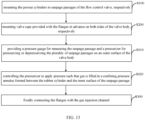
- the present application provides a mounting method for the gas flow control valve, including:
- mounting the porous cylinders in seepage passages of the flow control valve includes:
- the mounting method further includes:
- the present application provides a porous cylinder, a gas flow control valve, and a mounting method for the gas flow control valve.
- the porous cylinder includes a pipe and a plurality of pipe bundles filled inside the pipe along a length direction of the pipe. A single flow passage is formed in each of the pipe bundles, such that a seepage passage is formed inside the pipe.
- the inner diameter, the length and the permeability of the pipe bundle are determined in advance based on a Reynolds number for characterizing the flow state of the gas flowing through the pipe, and the Reynolds number is a positive number smaller than 2300.
- Embodiments of the present disclosure provide a method for characterizing the stability of gas seepage, by which the limits of geometric parameters of porous media under different temperature and pressure conditions are determined, which provides a theoretical basis for application, and effectively realizes stable gas flow in the gas injection channel, thus playing an auxiliary role in improving the application effect of the gas injection technology.
- Embodiments of the present disclosure further provide two porous cylinders. Firstly, the method for characterizing the stability of gas seepage is understood, and then the porous cylinder is designed by the method, so as to be able to effectively realize the stable gas flow in the gas injection channel, thereby playing an auxiliary role in improving the application effect of the gas injection technology.
- Embodiments of the present disclosure further provide a gas flow control valve and a mounting method thereof, which can effectively realize the stable gas flow in the gas injection channel, enable stable gas flow, and can implement flow regulation in a certain range, thus effectively controlling the gas flow rate in the gas injection channel.
- the gas flow control valve capable of adjusting the flow rate is convenient to use and easy to adjust.
- a gas flow control valve with stable gas flow condition is designed by the method, so as to play an auxiliary role in improving the application effect of the gas injection technology.
- the Reynolds number is used as a standard to establish the method for characterizing stable gas seepage, and determine the adjustment parameters to realize the feasibility of application.
- the "slippage effect” or “Klinkenberg effect” of the gas is expressed as below: the gas permeability measured with the same rock and the same gas at different average pressures is different. There is a good linear relationship between the permeability and the reciprocal of the evaluation pressure. Taking the measurement of the air permeability of a rock sample as an example, referring to FIG. 1 , P average is an average of the inlet pressure and the outlet pressure. The air permeability value corresponding to the original position in FIG. 1 denotes the liquid equivalent permeability.
- the porous media flow state can also be regarded as the state when the pipe gradually shrinks to the level of a tiny pore, and a pipe flow equation is first used for analysis as below.
- the flow state of pipe flow is usually characterized by Reynolds number, which is a dimensionless number.
- R e ⁇ vd ⁇
- v, ⁇ and ⁇ respectively denote the flow rate, density, and viscosity coefficient of the fluid
- d denotes the characteristic length, which is the equivalent diameter of the pipe in the case of a round pipe
- d denotes.
- the Reynolds number is usually used as a basis for judging the flow characteristics, and in pipe flow, Re ⁇ 2300 denotes laminar flow, Re denotes transitional state in the range of 2300 ⁇ 4000, and Re > 4000 denotes turbulent flow.
- the Reynolds number is small, the viscous force is the main factor, and the pressure term is balanced mainly with the viscous force term; if the Reynolds number is large, the viscous force term becomes the minor factor, and the pressure term is balanced mainly with the inertial force term.
- resistance is proportional to speed, viscosity, and characteristic length.
- resistance is substantially proportional to the square of velocity, the square of the density, and the square of the characteristic length.
- the seepage is essentially using the large resistance of the porous structure to reduce the pipe flow with high-velocity and conforms to the Darcy's law, so the laminar flow is taken as the boundary of stable flow, that is, it is feasible to use Re ⁇ 2300 in pipe flow as the boundary value of the seepage state.
- the following procedure is performed to convert an unstable flow into a stable flow with the flow rate remaining unchanged.
- This can be achieved by using porous structure with tiny pores in the rock structure.
- the resistance can be adjusted by changing the degree of density and length of the porous structure.
- the degree of density is reflected by the number of pores per unit area of rock structure and the diameter of pores. Obviously, the greater the number of the pores is and the smaller the diameter of the pores is, the lower the Reynolds number Re in a single pipe is.
- Changing the length can also achieve the purpose of changing the resistance under the condition that the degree of density is constant. As the length and the resistance increases, the Reynolds number Re decreases, and it is known that there is a length limit value L lim , so that the flow state becomes a stable laminar flow state.
- the pipe bundles with an inner diameter of 3 mm are used, and if the flow rate is calculated in the unit of 100 pieces of pipe bundles, the flow rate of a single pipe bundle is reduced by 100 times, then the flow rate Re is about 67,000, and the unstable state is reduced, but is still serious.
- an embodiment of the present application provides a porous cylinder.
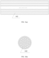
- the porous cylinder 1 specifically including: a pipe 11 for being provided within a gas injection channel and a plurality of pipe bundles 12 filled inside the pipe11 along a length direction of the pipe 11.
- a single flow passage 13 is formed in each of the pipe bundles 12, such that a seepage passage 25 is formed within the pipe 11.
- the inner diameter, length and permeability of the pipe bundle 12 are determined in advance based on a Reynolds number for characterizing the flow state of the gas flowing through the pipe 11, and the Reynolds number is a positive number smaller than 2300.
- the pore diameter is analyzed above, and the length limit value L lim of the porous media (porous cylinder) is related to the specific pressure value, pressure difference and pore density (permeability), however, the actual test adjustment is very simple.
- a gas flow control valve 2 is provided in the middle of the pipe 11.
- the core component of the gas flow control valve 2 is the porous cylinder 1, which is a porous structure.
- the pore density (permeability) of the porous cylinder 1 needs to be specifically designed, and the length of the porous cylinder 1 is not lower than the limit value L lim .
- the flow rate of the gas flowing into the pipe 11 is Q tin
- the flow rate of the gas flowing through the porous structure is Q po
- the flow rate of the gas flowing out of the pipe 11 is Q tout , which are obviously equal to each other.
- FIG. 5 (b) is a section A-A' of the pipe 11 connected to the gas flow control valve 2 illustrated in FIG. 5 (a), FIG.
- the gas flow direction in FIG. 5 (d) is from the left pipe towards the right pipe.
- the gas in the left pipe is in an unstable flow state.
- the flow state of the gas changes gradually to become a stable flow state, and maintains the stable flow state over an effective length.
- the gas gradually changes from the stable flow state to become unstable, and changes to the unstable flow state again after flowing for a certain distance in the right pipe.
- the gas flow control valve 2 specifically includes: a tubular valve body 21, two valve caps 22 respectively provided at both ends of the valve body 21, and two flanges 23 respectively provided at both ends of the valve body 21. One side of each flange 23 is communicated with the gas injection channel 3, and the other side of each flange 23 is connected to the valve cap 22.
- the valve body 21 is provided therein with a plurality of tubular passages arranged in sequence along the horizontal direction of the valve body 21.
- the tubular passages include a pipe flow passage 24 and a plurality of seepage passages 25.
- the porous cylinder 1 is mounted in each of the seepage passages 25.
- connection channels 221 are provided in the valve cap 22, one end of each of the connection channels 221 communicates with the interior of each of the tubular passages, and the other end of each of the connection channels 221 is provided respectively with a valve stem 222, such that the gas in the gas injection channel 3 flows through the connection channel 221 corresponding to the valve stem 222 in an open state, and then flows into the tubular passage communicating with the connection channel 221.
- a sealing surface 223 on one side of the vacap 22 is used to connect to the valve body 21, and a pipe connecting surface 224 on the other side of the valve cap 22 is used to connect to the gas injection channel 3.
- An O-shaped ring groove 225 is provided at the connection channel 221.
- porous cylinders there are two porous cylinders 1, the interior of one of which forms a first seepage passage 251 and the interior of the other of which forms a second seepage passage 252.
- the interior of the valve body 21 is provided with three passages, namely, a pipe flow passage 24, a first seepage passage 251, and a second seepage passage 252 in this order.
- the seepage passages 25 communicate with each other, and a pressure measuring hole 254 and a pressurization and depressurization hole 255 are provided at the bottom of the second flow passage 252.
- a communication hole 253 is provided between the first seepage passage 251 and the second seepage passage 252.
- the pressure measuring hole 254 is provided between the second seepage passage 252 and the valve body 21.
- the pressurization and depressurization hole 255 is provided between the second seepage passage 252 and the valve body 21.
- a rubber cylinder 256 arranged in the length direction of the seepage passage 25 is provided in the seepage passage 25, and a sealing ring 257 is provided between the rubber cylinder 256 and the inner surface of each of the two ports of the seepage passage 25, such that a confining pressure annulus 258 is formed between the rubber cylinder 256 and the inner surface of the seepage passage 25.
- the rubber cylinder 256 is provided therein with supporting short pipes 259 respectively close to two ports of the seepage passage 25, and the porous cylinder 1 is connected between the two supporting short pipes 259.
- a sealing circle is provided on a side of the sealing ring 257 that is close to the port of the seepage passage 25, and the sealing circle may be an O-shaped ring 28.
- the porous cylinder is made of metal nanoparticles, with good pore size and distribution uniformity, and good pressure resistance (working pressure can reach 40 MPa).
- the description parameters of the porous cylinder are permeability, diameter and length.
- the pressurizer 27 is similar in structure to a hydraulic jack and can be manually operated to pressurize the confining pressure annulus 258. The details will not be repeated.
- the maximum daily gas production of a high-pressure nitrogen compressor is 10,000 Nm 3 /d, and the maximum output pressure is 25 MPa.
- the pressure is 20 to 23 MPa, and the daily gas production is 7000 to 9000 Nm3/d.
- Single well injection shall be implemented on the premise that the valve adjustment is ineffective.
- the pressure is 20 MPa
- the flow rate is 7,500 Nm 3 /d
- the flow rate still can not be adjusted to realize a constant injection effect.
- 19 hours of continuous injection has to be performed to achieve a design of 6,000 Nm 3 /d, and the injection is continued for 19 hours on the second day until the injection volume of this cycle is completed.
- the embodiment of the present application further provides a mounting method for a gas flow control valve 2.
- the mounting method for the gas flow control valve 2 specifically including:
- the step S100 of the mounting method for the gas flow control valve 2 specifically includes:
- the mounting method for the gas flow control valve 2 further specifically includes:
- a porous cylinder is preferably determined according to a working pressure of 21 MPa.
- the description parameters of the cylinder are permeability, diameter, and length.
- the diameter of the gas flow control valve 2 after processing is fixed, so that only the permeability and the length are preferably determined.
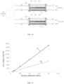
- FIG. 15 shows the relationship between gas volume and pressure difference for samples with a length of 7 cm and different permeabilities.
- FIG. 16 shows the relationship between gas volume and pressure difference for samples with a pressure difference of 0.05 MPa and different lengths.
- valve cap 22 is installed as below: a valve cap 22 with flanges 23 is mounted on both sides of the valve body 21 to ensure that the sealing circles are accurately positioned.
- a pressure gauge 26 and a pressurizer 27 are installed. After installation, the pressurizer 27 is used to pressurize the confining pressure annulus 258 to 0.1 MPa, so that the confining pressure annulus 258 is filled with gas and the inner parts such as the rubber cylinder 256 are fixed.
- the passage valves i.e., a first passage valve t11 and a second passage valve t21, of both of the gas flow control valves 2 are opened when the gas injection is started.
- the valves on both sides of the seepage passage k12 of the first gas flow control valve 2 are opened, and then the valves on both sides of the seepage passage k22 of the two gas flow control valves 2 are opened, and thereafter, the valves on both sides of the first passage valve t11 and the second passage valve t21 are slowly closed.
- the flow rate ratio Qout1: Qout2 output from the two gas flow control valves 2 approaches 2:1.
- this step may employ a paired combination of the seepage passage k13 and the seepage passage k23.
- the porous cylinder, the gas flow control valve and the mounting method for the gas flow control valve provided in the above embodiments of the present application has the following advantages:
- connection may be a fixed connection, a detachable connection or an integrated connection, or may be a mechanical connection or an electrical connection, or may be a direct connection, or may be an indirect connection through an intermediary, or an internal communication between two elements.
- connection may be a fixed connection, a detachable connection or an integrated connection, or may be a mechanical connection or an electrical connection, or may be a direct connection, or may be an indirect connection through an intermediary, or an internal communication between two elements.
Landscapes
- Engineering & Computer Science (AREA)
- General Engineering & Computer Science (AREA)
- Life Sciences & Earth Sciences (AREA)
- Geology (AREA)
- Mining & Mineral Resources (AREA)
- Physics & Mathematics (AREA)
- Fluid Mechanics (AREA)
- Mechanical Engineering (AREA)
- Geochemistry & Mineralogy (AREA)
- General Life Sciences & Earth Sciences (AREA)
- Environmental & Geological Engineering (AREA)
- Chemical & Material Sciences (AREA)
- Chemical Kinetics & Catalysis (AREA)
- Filling Or Discharging Of Gas Storage Vessels (AREA)
- Valve Housings (AREA)
- Pipe Accessories (AREA)
Claims (10)
- Gasstromregelventil (2), dadurch gekennzeichnet, dass das Gasstromregelventil (2) einen röhrenförmigen Ventilkörper (21), zwei Ventilkappen (22), die jeweils an beiden Enden des Ventilkörpers (21) bereitgestellt sind, und zwei Flansche (23), die jeweils an beiden Enden des Ventilkörpers (21) bereitgestellt sind, umfasst;wobei eine Seite des Flansches (23) mit einem Gasinjektionskanal (3) in Verbindung steht, und die andere Seite des Flansches (23) mit der Ventilkappe (22) verbunden ist;der Ventilkörper (21) darin mit einer Vielzahl von röhrenförmigen Durchgängen bereitgestellt ist, die in Folge entlang der horizontalen Richtung des Ventilkörpers (21) angeordnet sind, und die röhrenförmigen Durchgänge einen Rohrströmungsdurchgang (24) und eine Vielzahl von Sickerdurchgängen (25) umfassen;ein poröser Zylinder (1) in jedem der Sickerdurchgänge (25) montiert ist, jeder poröse Zylinder (1) ein Rohr (11) und eine Vielzahl von Rohrbündeln (12) umfasst, die in das Rohr (11) entlang einer Längsrichtung des Rohrs (11) gefüllt sind, wobei in jedem der Rohrbündel (12) ein einzelner Strömungsdurchgang (13) gebildet ist, sodass der Sickerdurchgang (25) im Inneren des Rohres (11) gebildet ist; wobei ein Innendurchmesser, eine Länge und eine Durchlässigkeit des Rohrbündels (12) im Voraus basierend auf einer Reynolds-Zahl zum Kennzeichnen des Strömungszustands des durch das Rohr (11) strömenden Gases bestimmt werden, und die Reynolds-Zahl eine positive Zahl kleiner als 2300 ist;eine Vielzahl von Verbindungskanälen (221) in der Ventilkappe (22) bereitgestellt sind, ein Ende jedes der Verbindungskanäle (221) mit einem Inneren eines jeden der röhrenförmigen Durchgänge in Verbindung steht, und das andere Ende jedes der Verbindungskanäle (221) jeweils mit einem Ventilschaft (222) bereitgestellt ist, sodass das Gas in dem Gasinjektionskanal durch den Verbindungskanal (221) strömt, der dem Ventilschaft (222) in einem offenen Zustand entspricht, und in den röhrenförmigen Durchgang strömt, der mit dem Verbindungskanal (221) in Verbindung steht.
- Gasstromregelventil nach Anspruch 1, wobei zwei poröse Zylinder (1) vorhanden sind, von denen das Innere des einen ersten Sickerdurchgang (251) und ein Inneres des anderen einen zweiten Sickerdurchgang (252) bildet.
- Gasstromregelventil nach Anspruch 2, wobei zwischen dem ersten Sickerdurchgang (251) und dem zweiten Sickerdurchgang (252) ein Verbindungsloch (253) bereitgestellt ist;
zwischen dem zweiten Sickerdurchgang (252) und dem Ventilkörper (21) ein Druckmessloch (254) bereitgestellt ist, und zwischen dem zweiten Sickerdurchgang (252) und dem Ventilkörper (21) ein Druckbeaufschlagungs- und Druckentlastungsloch (255) bereitgestellt ist. - Gasstromregelventil nach Anspruch 3, das weiter ein Druckmessgerät (26) und einen Druckhalter (27) umfasst, die an einer Außenoberfläche des Ventilkörpers (21) bereitgestellt sind;
wobei das Druckmessgerät (26) mit dem Druckmessloch (254) verbunden ist und der Druckhalter (27) mit dem Druckbeaufschlagungs- und Druckentlastungsloch (255) verbunden ist. - Gasstromregelventil nach Anspruch 1, wobei an der Verbindung zwischen einem Anschluss des Ventilkörpers (21) und der Ventilkappe (22) ein Dichtring bereitgestellt ist.
- Gasstromregelventil nach Anspruch 1, wobei ein in der Längsrichtung des Sickerdurchgangs angeordneter Gummizylinder (256) in dem Sickerdurchgang bereitgestellt ist, und ein Dichtring (257) zwischen dem Gummizylinder (256) und Innenoberflächen beider Anschlüsse des Sickerdurchgangs bereitgestellt ist, sodass zwischen dem Gummizylinder (256) und einer Innenoberfläche des Sickerdurchgangs ein begrenzender Niederdruckringraum (258) gebildet wird;der Gummizylinder (256) darin mit stützenden Kurzrohren (259) jeweils in der Nähe von zwei Anschlüssen des Sickerdurchgangs bereitgestellt ist;der poröse Zylinder (1) zwischen den beiden stützenden Kurzrohren (259) verbunden ist.
- Gasstromregelventil nach Anspruch 6, wobei ein Dichtkreis auf einer Seite des Dichtrings (257) bereitgestellt ist, der nahe dem Anschluss des Sickerdurchgangs liegt.
- Montageverfahren für ein Gasstromregelventil (2) nach einem der Ansprüche 1 bis 7, umfassend:Montieren der porösen Zylinder (1) jeweils in Sickerdurchgängen des Stromregelventils (1);Montieren von Ventilkappen (22), die mit den Flanschen (23) bereitgestellt sind, im Voraus auf beiden Seiten des Ventilkörpers (21); undfestes Verbinden der Flansche (23) mit dem Gasinjektionskanal (3).
- Montageverfahren für ein Gasstromregelventil nach Anspruch 8, wobei Montieren der porösen Zylinder (1) jeweils in Sickerdurchgängen des Stromregelventils (2) umfasst:Montieren jedes der porösen Zylinder (1) in einem Gummizylinder (256);Bereitstellen von stützenden Kurzrohren (259) in Lücken zwischen den porösen Zylindern (1) und Anschlüssen des Gummizylinders (256);Montieren von Dichtringen (257) jeweils auf beiden Seiten des Gummizylinders (256); undMontieren des Gummizylinders (256) in den Sickerdurchgang.
- Montageverfahren für ein Gasstromregelventil nach Anspruch 9, wobei nach dem Montieren von mit den Flanschen (23) bereitgestellten Ventilkappen (22) im Voraus jeweils auf beiden Seiten des Ventilkörpers (21) das Montageverfahren weiter umfasst:Bereitstellen eines Druckmessgerätes (26) zum Messen des Sickerdurchgangs und eines Druckhalters (27) zum Unterdrucksetzen oder Druckentlasten der Vielzahl von Sickerdurchgängen auf einer Außenoberfläche des Ventilkörpers (21);Steuern des Druckhalters (27), um Druck anzulegen, sodass Gas in einen zwischen dem Gummizylinder (256) und der Innenoberfläche des Sickerdurchgangs gebildeten begrenzenden Niederdruckringraum (258) gefüllt wird.
Applications Claiming Priority (2)
| Application Number | Priority Date | Filing Date | Title |
|---|---|---|---|
| CN202010446644.9A CN113719500B (zh) | 2020-05-25 | 2020-05-25 | 孔隙柱体、气体流量控制阀及气体流量控制阀的安装方法 |
| PCT/CN2021/094784 WO2021238754A1 (zh) | 2020-05-25 | 2021-05-20 | 孔隙柱体、气体流量控制阀及气体流量控制阀的安装方法 |
Publications (3)
| Publication Number | Publication Date |
|---|---|
| EP4159972A1 EP4159972A1 (de) | 2023-04-05 |
| EP4159972A4 EP4159972A4 (de) | 2023-11-15 |
| EP4159972B1 true EP4159972B1 (de) | 2025-02-26 |
Family
ID=78671503
Family Applications (1)
| Application Number | Title | Priority Date | Filing Date |
|---|---|---|---|
| EP21811773.7A Active EP4159972B1 (de) | 2020-05-25 | 2021-05-20 | Poröser zylinder, gasstromregelventil und montageverfahren für gasstromregelventil |
Country Status (4)
| Country | Link |
|---|---|
| US (1) | US12098783B2 (de) |
| EP (1) | EP4159972B1 (de) |
| CN (1) | CN113719500B (de) |
| WO (1) | WO2021238754A1 (de) |
Families Citing this family (5)
| Publication number | Priority date | Publication date | Assignee | Title |
|---|---|---|---|---|
| CN114575799A (zh) * | 2022-03-08 | 2022-06-03 | 西南石油大学 | 一种基于纳米-微纳米孔道结构驱替过程的实验装置 |
| US12091955B2 (en) | 2022-12-21 | 2024-09-17 | Scout Surface Solutions Llc | Fluid coupling assemblies for a manifold of a hydraulic fracturing system and related methods |
| CN117006417B (zh) * | 2023-09-01 | 2025-12-12 | 中石油深圳新能源研究院有限公司 | 一种减阻加压输油管道及输油系统 |
| CN117219409A (zh) * | 2023-10-09 | 2023-12-12 | 天津工业大学 | 一种油道不等宽的波纹式变压器散热器 |
| US12492625B1 (en) | 2025-02-20 | 2025-12-09 | Scout Surface Solutions Llc | Integrated junction and check valve assemblies for hydraulic fracturing system manifolds and related methods |
Family Cites Families (33)
| Publication number | Priority date | Publication date | Assignee | Title |
|---|---|---|---|---|
| US3327628A (en) * | 1965-10-22 | 1967-06-27 | Thiokol Chemical Corp | Method of and apparatus for quenching detonations |
| US3556157A (en) * | 1968-11-22 | 1971-01-19 | Corning Glass Works | Linear fluid restrictor having a variable coefficient of restriction and method for making the same |
| US5299453A (en) | 1993-01-28 | 1994-04-05 | Mobil Oil Corporation | Method for determining oil and water saturation of core samples at overburden pressure |
| US5307830A (en) * | 1993-05-18 | 1994-05-03 | Welker Engineering Company | Flow distribution method and apparatus reducing downstream turbulence |
| JPH0863235A (ja) * | 1994-08-24 | 1996-03-08 | Burutsukusu Instr Kk | 差圧式質量流量コントロール装置 |
| US6527050B1 (en) | 2000-07-31 | 2003-03-04 | David Sask | Method and apparatus for formation damage removal |
| WO2004010087A2 (en) * | 2002-07-19 | 2004-01-29 | Celerity Group, Inc | Flow sensor |
| US20040167726A1 (en) * | 2003-02-25 | 2004-08-26 | Rouss Gino James | Method of flow control |
| DE10317166A1 (de) * | 2003-04-15 | 2004-11-04 | Abb Research Ltd. | Gaszähleranordnung mit verbesserter Strömungsgeometrie |
| DE102006001417A1 (de) * | 2006-01-10 | 2007-07-12 | Endress + Hauser Flowtec Ag | Vorrichtung zur Umlenkung eines in einer Rohrleitung strömenden Mediums |
| TW200834275A (en) * | 2006-09-05 | 2008-08-16 | Celerity Inc | Multi-gas flow device |
| CN101994501B (zh) * | 2009-08-24 | 2013-07-31 | 中国石油天然气股份有限公司 | 一种注氢气采油方法 |
| CN101818637B (zh) * | 2010-04-26 | 2012-11-21 | 中国石油天然气股份有限公司 | 一种通过控制火烧注气速度提高厚层块状稠油油藏采收率的方法 |
| CN102053054A (zh) * | 2010-11-12 | 2011-05-11 | 清华大学 | 一种现场测量填埋堆体气体渗透系数的方法 |
| CA2847609C (en) | 2011-09-08 | 2016-10-11 | Statoil Petroleum As | A method and an arrangement for controlling fluid flow into a production pipe |
| US9068870B2 (en) * | 2013-02-27 | 2015-06-30 | Daniel Measurement And Control, Inc. | Ultrasonic flow metering with laminar to turbulent transition flow control |
| CN103398747B (zh) * | 2013-08-07 | 2016-04-13 | 陕西天仪智能仪表有限公司 | 一种气体流量计及其应用方法 |
| CN105092446B (zh) | 2014-05-08 | 2018-03-23 | 中国海洋石油总公司 | 一种模拟层内非均质性的二维可视渗流实验方法 |
| CN205049188U (zh) | 2015-09-23 | 2016-02-24 | 西安若水电气设备有限公司 | 一种层流流量计 |
| CN105651574B (zh) | 2016-01-13 | 2018-12-25 | 中国石油天然气股份有限公司 | 定性分析多孔介质中毛细作用的微米级毛细管束模型及制法 |
| CN105823517B (zh) * | 2016-05-09 | 2019-05-10 | 西北工业大学 | 差压线性流量计 |
| CN105953848B (zh) * | 2016-05-23 | 2019-07-05 | 西北工业大学 | 一种差压线性流量计 |
| CN106979918B (zh) | 2017-04-20 | 2020-02-07 | 中国石油大学(北京) | 一种获取致密油藏岩心的液体渗透率的方法及装置 |
| CN108729874A (zh) * | 2017-04-24 | 2018-11-02 | 陕西星海控制设备有限公司 | 一种智能恒流稳压配气阀组装置 |
| CN206757417U (zh) * | 2017-04-25 | 2017-12-15 | 北京七星华创流量计有限公司 | 质量流量控制器及流量控制系统 |
| CN107525746B (zh) | 2017-08-11 | 2020-06-30 | 中国石油大学(北京) | 一种表征致密油藏低速非达西渗流特征的方法及装置 |
| US20200248838A1 (en) * | 2017-10-27 | 2020-08-06 | S.P.M. Flow Control, Inc. | Flow restrictor for a plug valve |
| CN108345322A (zh) * | 2018-04-16 | 2018-07-31 | 成都正升能源技术开发有限公司 | 一种无线注气流量控制一体化装置 |
| CN110185407B (zh) * | 2019-04-28 | 2024-03-26 | 南京伟业机械有限公司 | 一种带安全阀及控制系统的注气井口装置 |
| CN110309611B (zh) | 2019-07-08 | 2020-09-29 | 中国石油大学(北京) | 基于气水厚度分布的气水两相渗流规律预测方法及系统 |
| CN110441205A (zh) | 2019-07-25 | 2019-11-12 | 太原理工大学 | 一种基于直毛管模型的弱胶结砂岩渗透率评估方法 |
| CN110567858B (zh) | 2019-10-17 | 2020-11-03 | 西南石油大学 | 一种基于分形理论的预测页岩纳米孔隙渗透率的方法 |
| CN113719501B (zh) * | 2020-05-25 | 2024-06-25 | 中国石油天然气股份有限公司 | 气体流量调控管、气体流量稳定控制阀、系统及安装方法 |
-
2020
- 2020-05-25 CN CN202010446644.9A patent/CN113719500B/zh active Active
-
2021
- 2021-05-20 WO PCT/CN2021/094784 patent/WO2021238754A1/zh not_active Ceased
- 2021-05-20 US US17/999,722 patent/US12098783B2/en active Active
- 2021-05-20 EP EP21811773.7A patent/EP4159972B1/de active Active
Also Published As
| Publication number | Publication date |
|---|---|
| CN113719500A (zh) | 2021-11-30 |
| US20230258282A1 (en) | 2023-08-17 |
| WO2021238754A1 (zh) | 2021-12-02 |
| CN113719500B (zh) | 2022-10-04 |
| EP4159972A4 (de) | 2023-11-15 |
| US12098783B2 (en) | 2024-09-24 |
| EP4159972A1 (de) | 2023-04-05 |
Similar Documents
| Publication | Publication Date | Title |
|---|---|---|
| EP4159972B1 (de) | Poröser zylinder, gasstromregelventil und montageverfahren für gasstromregelventil | |
| CN109001243B (zh) | 一种采用低场核磁共振评价煤的动态水锁效应的方法与装置 | |
| CN103712834B (zh) | 基于深井取样的室内保真取样、存样与分析装置及方法 | |
| CN104713812B (zh) | 一种基于岩心气测渗透率测量装置的校正方法 | |
| CN111237485B (zh) | 一种实时监测气体流量的阀门及阀门流量测量方法 | |
| CN113866069B (zh) | 一种页岩岩心渗透率实验装置和方法 | |
| WO2007060386A8 (en) | Isokinetic sampling method and system for multiphase flow from subterranean wells | |
| CN103969165A (zh) | 瞬态稳态同时测试致密岩石渗透率的装置及方法 | |
| CN203929584U (zh) | 一种瞬态稳态同时测试致密岩石渗透率的装置 | |
| CN112683748B (zh) | 一种压裂物理模拟过程中煤岩动态渗透率测试装置及方法 | |
| CN112557276B (zh) | 一种同时测量多孔介质渗透率和孔隙率的方法 | |
| KR101384386B1 (ko) | 저 투과성 암체의 물성 측정 시스템 | |
| CN113916744B (zh) | 一种总应力下泡沫土渗透系数测试方法及系统 | |
| CN107014698A (zh) | 一种岩石高温压缩系数和渗透率的测量装置及测量方法 | |
| CN112818513A (zh) | 裂缝性页岩渗透率的评价方法和评估模型及其构建方法 | |
| US8695414B2 (en) | High pressure and flow rate pump useful in formation fluid sample testing | |
| CN111720111A (zh) | 一种基于定产量生产的产水气井生产模拟装置及方法 | |
| RU2810389C1 (ru) | Клапан управления потоком газа и способ установки клапана управления потоком газа | |
| CN113719501A (zh) | 气体流量调控管、气体流量稳定控制阀、系统及安装方法 | |
| CN215413867U (zh) | 一种油田气体流量测量装置 | |
| CN114577702B (zh) | 一种持续冻融型水合物储层渗透性气体测量装置及方法 | |
| CN206339467U (zh) | 岩心孔隙度测量装置 | |
| CN112561223B (zh) | 油气井增产潜力的定量评价方法 | |
| CN116106192A (zh) | 纹层状页岩气测渗透率测试方法 | |
| CN209102578U (zh) | 用于裂隙表面粗糙度表征的渗流试验系统 |
Legal Events
| Date | Code | Title | Description |
|---|---|---|---|
| STAA | Information on the status of an ep patent application or granted ep patent |
Free format text: STATUS: THE INTERNATIONAL PUBLICATION HAS BEEN MADE |
|
| PUAI | Public reference made under article 153(3) epc to a published international application that has entered the european phase |
Free format text: ORIGINAL CODE: 0009012 |
|
| STAA | Information on the status of an ep patent application or granted ep patent |
Free format text: STATUS: REQUEST FOR EXAMINATION WAS MADE |
|
| 17P | Request for examination filed |
Effective date: 20221222 |
|
| AK | Designated contracting states |
Kind code of ref document: A1 Designated state(s): AL AT BE BG CH CY CZ DE DK EE ES FI FR GB GR HR HU IE IS IT LI LT LU LV MC MK MT NL NO PL PT RO RS SE SI SK SM TR |
|
| DAV | Request for validation of the european patent (deleted) | ||
| DAX | Request for extension of the european patent (deleted) | ||
| A4 | Supplementary search report drawn up and despatched |
Effective date: 20231016 |
|
| RIC1 | Information provided on ipc code assigned before grant |
Ipc: F16L 55/027 20060101ALI20231010BHEP Ipc: F16K 21/00 20060101ALI20231010BHEP Ipc: F16K 47/08 20060101ALI20231010BHEP Ipc: G05D 7/01 20060101ALI20231010BHEP Ipc: F15D 1/02 20060101ALI20231010BHEP Ipc: E21B 34/02 20060101ALI20231010BHEP Ipc: E21B 43/16 20060101AFI20231010BHEP |
|
| GRAP | Despatch of communication of intention to grant a patent |
Free format text: ORIGINAL CODE: EPIDOSNIGR1 |
|
| STAA | Information on the status of an ep patent application or granted ep patent |
Free format text: STATUS: GRANT OF PATENT IS INTENDED |
|
| INTG | Intention to grant announced |
Effective date: 20241004 |
|
| GRAS | Grant fee paid |
Free format text: ORIGINAL CODE: EPIDOSNIGR3 |
|
| GRAA | (expected) grant |
Free format text: ORIGINAL CODE: 0009210 |
|
| STAA | Information on the status of an ep patent application or granted ep patent |
Free format text: STATUS: THE PATENT HAS BEEN GRANTED |
|
| AK | Designated contracting states |
Kind code of ref document: B1 Designated state(s): AL AT BE BG CH CY CZ DE DK EE ES FI FR GB GR HR HU IE IS IT LI LT LU LV MC MK MT NL NO PL PT RO RS SE SI SK SM TR |
|
| REG | Reference to a national code |
Ref country code: GB Ref legal event code: FG4D |
|
| REG | Reference to a national code |
Ref country code: CH Ref legal event code: EP |
|
| REG | Reference to a national code |
Ref country code: DE Ref legal event code: R096 Ref document number: 602021026874 Country of ref document: DE |
|
| REG | Reference to a national code |
Ref country code: IE Ref legal event code: FG4D |
|
| REG | Reference to a national code |
Ref country code: NL Ref legal event code: MP Effective date: 20250226 |
|
| PG25 | Lapsed in a contracting state [announced via postgrant information from national office to epo] |
Ref country code: RS Free format text: LAPSE BECAUSE OF FAILURE TO SUBMIT A TRANSLATION OF THE DESCRIPTION OR TO PAY THE FEE WITHIN THE PRESCRIBED TIME-LIMIT Effective date: 20250526 |
|
| PG25 | Lapsed in a contracting state [announced via postgrant information from national office to epo] |
Ref country code: FI Free format text: LAPSE BECAUSE OF FAILURE TO SUBMIT A TRANSLATION OF THE DESCRIPTION OR TO PAY THE FEE WITHIN THE PRESCRIBED TIME-LIMIT Effective date: 20250226 |
|
| PG25 | Lapsed in a contracting state [announced via postgrant information from national office to epo] |
Ref country code: PL Free format text: LAPSE BECAUSE OF FAILURE TO SUBMIT A TRANSLATION OF THE DESCRIPTION OR TO PAY THE FEE WITHIN THE PRESCRIBED TIME-LIMIT Effective date: 20250226 |
|
| PG25 | Lapsed in a contracting state [announced via postgrant information from national office to epo] |
Ref country code: ES Free format text: LAPSE BECAUSE OF FAILURE TO SUBMIT A TRANSLATION OF THE DESCRIPTION OR TO PAY THE FEE WITHIN THE PRESCRIBED TIME-LIMIT Effective date: 20250226 |
|
| REG | Reference to a national code |
Ref country code: LT Ref legal event code: MG9D |
|
| PG25 | Lapsed in a contracting state [announced via postgrant information from national office to epo] |
Ref country code: NO Free format text: LAPSE BECAUSE OF FAILURE TO SUBMIT A TRANSLATION OF THE DESCRIPTION OR TO PAY THE FEE WITHIN THE PRESCRIBED TIME-LIMIT Effective date: 20250526 Ref country code: IS Free format text: LAPSE BECAUSE OF FAILURE TO SUBMIT A TRANSLATION OF THE DESCRIPTION OR TO PAY THE FEE WITHIN THE PRESCRIBED TIME-LIMIT Effective date: 20250626 |
|
| PG25 | Lapsed in a contracting state [announced via postgrant information from national office to epo] |
Ref country code: NL Free format text: LAPSE BECAUSE OF FAILURE TO SUBMIT A TRANSLATION OF THE DESCRIPTION OR TO PAY THE FEE WITHIN THE PRESCRIBED TIME-LIMIT Effective date: 20250226 |
|
| PG25 | Lapsed in a contracting state [announced via postgrant information from national office to epo] |
Ref country code: HR Free format text: LAPSE BECAUSE OF FAILURE TO SUBMIT A TRANSLATION OF THE DESCRIPTION OR TO PAY THE FEE WITHIN THE PRESCRIBED TIME-LIMIT Effective date: 20250226 |
|
| PG25 | Lapsed in a contracting state [announced via postgrant information from national office to epo] |
Ref country code: PT Free format text: LAPSE BECAUSE OF FAILURE TO SUBMIT A TRANSLATION OF THE DESCRIPTION OR TO PAY THE FEE WITHIN THE PRESCRIBED TIME-LIMIT Effective date: 20250626 Ref country code: LV Free format text: LAPSE BECAUSE OF FAILURE TO SUBMIT A TRANSLATION OF THE DESCRIPTION OR TO PAY THE FEE WITHIN THE PRESCRIBED TIME-LIMIT Effective date: 20250226 |
|
| PG25 | Lapsed in a contracting state [announced via postgrant information from national office to epo] |
Ref country code: BG Free format text: LAPSE BECAUSE OF FAILURE TO SUBMIT A TRANSLATION OF THE DESCRIPTION OR TO PAY THE FEE WITHIN THE PRESCRIBED TIME-LIMIT Effective date: 20250226 Ref country code: GR Free format text: LAPSE BECAUSE OF FAILURE TO SUBMIT A TRANSLATION OF THE DESCRIPTION OR TO PAY THE FEE WITHIN THE PRESCRIBED TIME-LIMIT Effective date: 20250527 |
|
| REG | Reference to a national code |
Ref country code: AT Ref legal event code: MK05 Ref document number: 1770782 Country of ref document: AT Kind code of ref document: T Effective date: 20250226 |
|
| PG25 | Lapsed in a contracting state [announced via postgrant information from national office to epo] |
Ref country code: SE Free format text: LAPSE BECAUSE OF FAILURE TO SUBMIT A TRANSLATION OF THE DESCRIPTION OR TO PAY THE FEE WITHIN THE PRESCRIBED TIME-LIMIT Effective date: 20250226 |
|
| PG25 | Lapsed in a contracting state [announced via postgrant information from national office to epo] |
Ref country code: SM Free format text: LAPSE BECAUSE OF FAILURE TO SUBMIT A TRANSLATION OF THE DESCRIPTION OR TO PAY THE FEE WITHIN THE PRESCRIBED TIME-LIMIT Effective date: 20250226 |
|
| PG25 | Lapsed in a contracting state [announced via postgrant information from national office to epo] |
Ref country code: DK Free format text: LAPSE BECAUSE OF FAILURE TO SUBMIT A TRANSLATION OF THE DESCRIPTION OR TO PAY THE FEE WITHIN THE PRESCRIBED TIME-LIMIT Effective date: 20250226 |
|
| PG25 | Lapsed in a contracting state [announced via postgrant information from national office to epo] |
Ref country code: IT Free format text: LAPSE BECAUSE OF FAILURE TO SUBMIT A TRANSLATION OF THE DESCRIPTION OR TO PAY THE FEE WITHIN THE PRESCRIBED TIME-LIMIT Effective date: 20250226 |
|
| PG25 | Lapsed in a contracting state [announced via postgrant information from national office to epo] |
Ref country code: AT Free format text: LAPSE BECAUSE OF FAILURE TO SUBMIT A TRANSLATION OF THE DESCRIPTION OR TO PAY THE FEE WITHIN THE PRESCRIBED TIME-LIMIT Effective date: 20250226 |
|
| PG25 | Lapsed in a contracting state [announced via postgrant information from national office to epo] |
Ref country code: EE Free format text: LAPSE BECAUSE OF FAILURE TO SUBMIT A TRANSLATION OF THE DESCRIPTION OR TO PAY THE FEE WITHIN THE PRESCRIBED TIME-LIMIT Effective date: 20250226 Ref country code: CZ Free format text: LAPSE BECAUSE OF FAILURE TO SUBMIT A TRANSLATION OF THE DESCRIPTION OR TO PAY THE FEE WITHIN THE PRESCRIBED TIME-LIMIT Effective date: 20250226 |
|
| PG25 | Lapsed in a contracting state [announced via postgrant information from national office to epo] |
Ref country code: RO Free format text: LAPSE BECAUSE OF FAILURE TO SUBMIT A TRANSLATION OF THE DESCRIPTION OR TO PAY THE FEE WITHIN THE PRESCRIBED TIME-LIMIT Effective date: 20250226 |
|
| PG25 | Lapsed in a contracting state [announced via postgrant information from national office to epo] |
Ref country code: SK Free format text: LAPSE BECAUSE OF FAILURE TO SUBMIT A TRANSLATION OF THE DESCRIPTION OR TO PAY THE FEE WITHIN THE PRESCRIBED TIME-LIMIT Effective date: 20250226 |
|
| REG | Reference to a national code |
Ref country code: DE Ref legal event code: R097 Ref document number: 602021026874 Country of ref document: DE |
|
| REG | Reference to a national code |
Ref country code: DE Ref legal event code: R119 Ref document number: 602021026874 Country of ref document: DE |
|
| REG | Reference to a national code |
Ref country code: CH Ref legal event code: H13 Free format text: ST27 STATUS EVENT CODE: U-0-0-H10-H13 (AS PROVIDED BY THE NATIONAL OFFICE) Effective date: 20251223 |
|
| PLBE | No opposition filed within time limit |
Free format text: ORIGINAL CODE: 0009261 |
|
| STAA | Information on the status of an ep patent application or granted ep patent |
Free format text: STATUS: NO OPPOSITION FILED WITHIN TIME LIMIT |
|
| PG25 | Lapsed in a contracting state [announced via postgrant information from national office to epo] |
Ref country code: LU Free format text: LAPSE BECAUSE OF NON-PAYMENT OF DUE FEES Effective date: 20250520 |
|
| PG25 | Lapsed in a contracting state [announced via postgrant information from national office to epo] |
Ref country code: CH Free format text: LAPSE BECAUSE OF NON-PAYMENT OF DUE FEES Effective date: 20250531 |
|
| GBPC | Gb: european patent ceased through non-payment of renewal fee |
Effective date: 20250526 |
|
| REG | Reference to a national code |
Ref country code: BE Ref legal event code: MM Effective date: 20250531 |
|
| PG25 | Lapsed in a contracting state [announced via postgrant information from national office to epo] |
Ref country code: MC Free format text: LAPSE BECAUSE OF FAILURE TO SUBMIT A TRANSLATION OF THE DESCRIPTION OR TO PAY THE FEE WITHIN THE PRESCRIBED TIME-LIMIT Effective date: 20250226 |
|
| 26N | No opposition filed |
Effective date: 20251127 |
|
| PG25 | Lapsed in a contracting state [announced via postgrant information from national office to epo] |
Ref country code: GB Free format text: LAPSE BECAUSE OF NON-PAYMENT OF DUE FEES Effective date: 20250526 |
|
| PG25 | Lapsed in a contracting state [announced via postgrant information from national office to epo] |
Ref country code: DE Free format text: LAPSE BECAUSE OF NON-PAYMENT OF DUE FEES Effective date: 20251202 Ref country code: IE Free format text: LAPSE BECAUSE OF NON-PAYMENT OF DUE FEES Effective date: 20250520 |
|
| PG25 | Lapsed in a contracting state [announced via postgrant information from national office to epo] |
Ref country code: BE Free format text: LAPSE BECAUSE OF NON-PAYMENT OF DUE FEES Effective date: 20250531 |
|
| PGFP | Annual fee paid to national office [announced via postgrant information from national office to epo] |
Ref country code: FR Payment date: 20260309 Year of fee payment: 6 |