EP4159970B1 - Verfahren und system zum elektroimpulsbohren - Google Patents
Verfahren und system zum elektroimpulsbohren Download PDFInfo
- Publication number
- EP4159970B1 EP4159970B1 EP21199973.5A EP21199973A EP4159970B1 EP 4159970 B1 EP4159970 B1 EP 4159970B1 EP 21199973 A EP21199973 A EP 21199973A EP 4159970 B1 EP4159970 B1 EP 4159970B1
- Authority
- EP
- European Patent Office
- Prior art keywords
- drill head
- electrodes
- electric arcs
- drilling
- gap distance
- Prior art date
- Legal status (The legal status is an assumption and is not a legal conclusion. Google has not performed a legal analysis and makes no representation as to the accuracy of the status listed.)
- Active
Links
Images


Classifications
-
- E—FIXED CONSTRUCTIONS
- E21—EARTH OR ROCK DRILLING; MINING
- E21B—EARTH OR ROCK DRILLING; OBTAINING OIL, GAS, WATER, SOLUBLE OR MELTABLE MATERIALS OR A SLURRY OF MINERALS FROM WELLS
- E21B7/00—Special methods or apparatus for drilling
- E21B7/007—Drilling by use of explosives
-
- E—FIXED CONSTRUCTIONS
- E21—EARTH OR ROCK DRILLING; MINING
- E21B—EARTH OR ROCK DRILLING; OBTAINING OIL, GAS, WATER, SOLUBLE OR MELTABLE MATERIALS OR A SLURRY OF MINERALS FROM WELLS
- E21B7/00—Special methods or apparatus for drilling
- E21B7/14—Drilling by use of heat, e.g. flame drilling
- E21B7/15—Drilling by use of heat, e.g. flame drilling of electrically generated heat
-
- E—FIXED CONSTRUCTIONS
- E21—EARTH OR ROCK DRILLING; MINING
- E21C—MINING OR QUARRYING
- E21C37/00—Other methods or devices for dislodging with or without loading
- E21C37/18—Other methods or devices for dislodging with or without loading by electricity
Definitions
- the invention relates to a method for drilling by means of a drill head with an end portion, wherein at least two electrodes are arranged at the end portion.
- the invention also relates to a system for performing pulsed drilling operations.
- the invention relates to an optical sensor for use in a system for performing pulsed drilling operations.
- the invention relates to a computer program product.
- Electro-pulse drilling employs pulsed-power technology for drilling into materials such as rock formations, mineral lumps, etc.
- a conduction path is created inside the material which can result in breaking of the material.
- the electro-pulse drill head has at least two electrodes.
- An electrical potential is applied across the electrodes which contact the material, generating a high electric field, which results in the formation of an arc or plasma inside the material (e.g. rock).
- the arc travels from a high voltage electrode to a low voltage electrode of the electro-pulse drill head.
- the electrical current flows through the conduction path, or arc, through the surface and inside the material, and results in the expansion inside the material which can create high stress or pressures.
- These induced high pressures and generated tensions can result in structural failure of the material, thus effectively fracturing the surrounding material and creating fragments (e.g. fragmented rock).
- the fragments can be carried away from the drill head, for instance by means of drilling fluid, and the drill head can be advanced further in the borehole.
- the arcs may be repeatedly generated arcs for incremental fracturing of the material during the drilling process.
- the invention provides for a method of drilling by means of a drill head with an end portion, wherein at least two electrodes are arranged at the end portion, the method comprising: moving, by means of an actuation system, the drill head adjacent to a surface to be broken up; applying, by means of a voltage generator, a voltage between the electrodes resulting in one or more electric discharges between the electrodes, the one or more discharges resulting in one or more electric arcs for breaking up the surface; and wherein a gap distance is provided between the at least two electrodes of the drill head and the surface during generation of the one or more electric arcs.
- the electro-pulse boring/drilling can be significantly improved.
- the drill head is better capable of breaking up the surface opposite to the drill head.
- larger debris broken off of the surface may be obtained.
- the separation between the extending electrodes of the drill head and the opposite surface to be broken up enables more easy removal of larger pieces of the surface broken off (i.e. debris).
- the boring/drilling speed and/or the rate of penetration achieved by the electro-pulse drill head can be significantly improved.
- the rate of penetration can be seen as the speed at which the drill head can be moved forward during drilling/boring.
- the rate of penetration provides an indication of the efficiency of the drill head in drilling/boring rock or the like, which can be improved by providing a gap distance between the at least two electrodes of the drill head and the surface during generation of the one or more electric arcs.
- the method comprises: measuring, by means of a sensor measurement system, at least one value indicative of a property of the generated one or more electric arcs; and controlling, by means of a control system, one or more operational parameters of the actuation system such as to adjust the gap distance between the drill head and the surface based on the at least one value.
- the sensor measurement system may be used for determining the effectiveness of the electro-pulse drilling/boring. This provides a way faster approach than for instance measuring a value indicative of debris (e.g. weighing debris), since flushing debris may be a slower process, making it less interesting for use for control. For example, it can take some time for the debris to be flushed away out of the drill hole.
- a value indicative of debris e.g. weighing debris
- the sensor measurement system comprises an optical sensor configured to measure a value indicative of a length of time of the one or more electric arcs.
- the length of time (cf. duration) of an electric arc provides an efficient way of determining whether the electric arc has passed through the surface (e.g. rock) properly.
- the duration of the electric arc can be measured in different ways.
- the gap distance may be in a predetermined range, and within said predetermined range, one or more operational parameters may be further adjusted to obtain better electric arcs. For this a feedback loop may be provided.
- the gap distance may be variably adjusted within the predetermined range, further taking into account values provided by the sensor measurement system, such as for instance a value indicative or related to a duration of the generated individual electric arcs.
- a longer pulse duration may be an indication that the arc has travelled through the drilling fluid.
- a shorter pulse duration may indicate that the arc has travelled through the surface (e.g. rock) being bored.
- the pulse duration is very small, for example smaller than 1 microsecond. This may be difficult to measure. However, an optical sensor may provide the ability to accurately measure such small lengths of time.
- the pulse durations may be in a range between 100-3000 nanoseconds, more preferably between 300-2000 nanoseconds.
- the gap distance is not measured, but it is checked whether the generated electric arcs or pulses have certain properties, providing an indication of the gap distance.
- the gap distance may be optimal in a predetermined range. In this way, by monitoring parameters indicative of properties of the generated electric arcs or pulses, it can indirectly be determined whether the electrodes are suitable distanced from the surface being drilled.
- control system is configured to operate one or more actuators to dynamically optimize the gap distance based on the sensory data obtained by means of the sensor measurement system.
- the optical sensor is arranged at the voltage generator.
- properties related to the generated arcs at the electrodes of the drill head can be effectively measured at the voltage generator. This may provide in more robust and reliable monitoring.
- control system may be configured to control electrical parameters in the voltage generator based on the at least one value indicative of the property of the generated one or more electric arcs. Additionally or alternatively, the control system may be configured to control the flushing speed based on the at least one value. Since, it can be expected that less debris are produced due to the generated arcs, when the generated arcs fail to travel through the surface being drilled.
- the voltage generator is integrated with the drill head.
- the optical sensor is arranged at the drill head.
- the generated arcs at the electrodes of the drill head can be sensed by means of the optical sensor. It is also possible to have multiple optical sensors, for example arranged at the voltage generator and at the electrodes of the drill head.
- an acoustic sensor and/or a vibrational sensor e.g. accelerometer
- an optical sensor may provide significant advantages.
- an aggressive electromagnetic interference (EMI) environment may be obtained. This can make it challenging to effectively use sensors with electronics, such as electronic sensors.
- additional shielding is provided in order to protect such sensors against the electromagnetic radiation.
- the effect of electromagnetic interference may be reduced by placing the sensors at a sufficient distance from the source of electromagnetic radiation.
- the optical sensors are not affected by the aggressive EMI environment and may thus not require such additional measures. The signals measured by means of the optical sensor may be measured without interference, even when employed in the aggressive EMI environment.
- the voltage generator charges and discharges sequentially, wherein the one or more electric arcs are generated during discharge.
- the voltage generator is a Marx generator.
- a voltage generator can create high-voltage pulse from a low voltage DC supply.
- the Marx generator may have a circuit which generates a high-voltage pulse by charging a number of capacitors in parallel, then suddenly connecting them in series. It will be appreciated that other types of high voltage generators for producing an arc/pulse may be used.
- the senor operates synchronous with the voltage generator.
- the senor is selectively disconnected based on the operation of the voltage generator.
- the sensor in case the voltage generator is charging, the sensor is operated such as to perform measurements, and in case the voltage generator is discharging (cf. generation of the one or more electric arcs), the sensor is disconnected. This may be performed by a switching circuit. In this way, electromagnetic interference resulting from the generated electric arcs may be effectively reduced or even prevented.
- sensors are employed which comprise electronics, e.g. electronic sensors which may be affected by electromagnetic interference.
- the value indicative of the length of time of the one or more electric arcs is associated to the traveled path of said one or more electric arcs.
- the pulse duration can be determined based on the sensory data, providing an indication of the path of the arcs.
- control system is configured to determine based on the value indicative of the length of time whether the one or more electric arcs have travelled into the surface to be broken up.
- Measuring a value indicative of the length of time of the one or more electric arcs, i.e. pulse duration can be done in different ways.
- a value indicative of the pulse duration is determined by means of a sensor at the voltage generator. This can be advantageous, since more accurate determinations may be achieved.
- the arcs going through the surface may result in effective fragmentation of the material, resulting in a more effective drilling process.
- the sensor measurement system comprises an electric sensor configured to measure a voltage and/or a current during generation of the one or more electric arcs.
- the voltage and/or current can be indicative of the travel path of the one or more electric arcs. In this way, it can be determined whether the one or more electric arcs or pulses pass through the surface properly.
- control system is configured to determine whether the length of time of the one or more electric arcs is smaller than a threshold value, wherein one or more operational parameters of the actuation system are adjusted for changing the gap distance between the drill head and the surface when the length of time of said one or more electric arcs is larger than the threshold value.
- Providing a split distance between each electrode and the opposite surface to be broken up, may result in improved debris forming. Direct contact between the electrodes and the surface may cause for smaller debris, which has detrimental effect on the efficiency and the rate of penetration and/or drilling speed.
- the efficiency and the drilling/boring speed can be significantly enhanced.
- the drill speed can be increased with a factor of at least 5, even at least 10 or more.
- a drilling fluid is used during pulsed drilling operation, wherein the drilling fluid has a dielectric constant which is higher than a dielectric constant of the surface to be broken up.
- the electric pulse cf. spark
- the electric pulse or spark goes through the substrate surface to be broken up, instead of solely between the drilling fluid from one electrode to another electrode. Even if there is no direct contact between the electrode and substrate surface to be broken up, the electric pulse or spark will still pass through the substrate surface and result in breaking thereof, forming debris which can be easily flushed.
- the dielectric constant of the drilling fluid is at least 5 times larger than the dielectric constant of the surface to be broken up, more preferably at least 10 times larger, even more preferably at least 20 times larger.
- the drilling fluid can act as a capacitor dielectric, resulting in the electric pulses or sparks going through the substrate surface, even with an interspace between the electrodes and said substrate surface.
- the drilling fluid is water based.
- the drilling liquid between the drill head and the surface to be broken up can be charged with an amount of energy without the voltage getting too high, thus acting as a capacitor.
- the permittivity is lower in the surface (e.g. rock, substrate, soil, etc. has a lower permittivity).
- the permittivity of a rock surface to be drilled may be 10 to 50 times lower than that of the drilling fluid (e.g. water), which causes the sparks or electric pulses to go through the rock surface.
- Water as drilling fluid may have far greater electric conductivity than oil. Additionally, water may result in less contamination of the environment, compared to the use of oil.
- any electrode of the at least two electrodes touches the surface to be drilled, at least during the generation of the electric arcs.
- a non-zero gap distance may be provided between the electrodes and the surface.
- the gap distance is kept above 1 millimeter, more preferably above 2 millimeter. By approaching the surface and maintaining such minimal gap distance, the optimal gap distance can be automatically reached. Therefore, it is possible to significantly simplify control during the electro-pulse drilling process.
- the gap distance is kept between 1 to 30 millimeter, more preferably between 2 to 10 millimeter, even more preferably between 2 to 5 millimeter.
- the gap distance may be selected independent of the dimensions of the drill head, such as the diameter of the drill head.
- the gap distance may also be selected independent of characteristics of the ground to be drilled/bored, such as for instance material properties. This is advantageous, since often the characteristics and the properties of the surface/substrate are not well known. For example, the rock may have heterogenous properties.
- no insulation may need to be arranged between the electrodes, as the generated electric arcs can travel into the surface. This may improve the flushing capabilities since the debris can more easily be flushed away.
- a spacing unit is provided for mechanically distancing the at least two electrodes of the drill head and the surface to be broken up.
- the spacing unit is preset.
- the drill head is continuously moved into the drill hole.
- the movement of the drill head into the drill hole may be carried out at a boring speed.
- the drill head may be continuously lowered in the drill hole.
- the drill head is moved into the drill hole with a boring speed, wherein the boring speed is adjusted based on the at least one value indicative of the property of the generated one or more electric arcs.
- the spacing unit is configured to keep a minimum distance between the drill head and the surface to be broken up.
- a self-regulating operation can be obtained with a rather simple design. Therefore, a more robust and reliable operation of the drill head control can be obtained.
- an optimal distance may be achieved since a minimal gap distance is always maintained such as to avoid direct contact between the electrodes and the surface.
- the electro-pulse drill head will efficiently bore/drill into the surface, causing pieces of the surface (e.g. rock) being broken off.
- the distance of the electrodes to the surface cf. gap distance
- the optimal distance will again be automatically reached, without requiring complex control systems for accurately determine the gap distance. This process can be facilitated by providing a spacing unit.
- the spacing unit is adjustable to allow variable minimal distances between the at least two electrodes and the surface to be drilled.
- the spacing unit has one or more mechanical fingers which extend from the end portion of the drill head towards the surface to be drilled. In this way, the mechanical fingers can contact the surface when the distance between the electrodes and the surface is reduced, preventing further reduction of the distance.
- a plurality of mechanical fingers are used for maintaining a minimum distance. It is also possible to employ braces or skirts for keeping the distance. The skirts may be shaped such as to facilitate flushing. Advantageously, the flushing can be improved whilst maintaining a minimum distance between the electrodes and the surface.
- the spacing unit may avoid that the electrodes directly rest on the surface during electric pulse drilling operation.
- the fingers may have various configurations, shapes and/or dimensions. For instance, feeler pens may be employed which can also measure a distance by contact. This distance can be used by the control system. In some examples, the fingers have springs reducing mechanical shocks. The fingers may include one or more sensors for detecting contact and/or the forces applied.
- At least one distance sensor is provided, wherein the at least one distance sensor is configured to provide data indicative of a distance of the electrodes from the surface to be broken up.
- the at least one distance sensor is configured to measure data indicative of the distance at least at a central portion of the on the front portion of the drill head.
- the at least one distance sensor is configured to measure data indicative of the distance at a plurality of points on the front portion of the drill head. In some examples, the plurality of points may for instance be evenly distributed on the front portion of the drill head.
- the at least one distance sensor may measure from a surface of the drill head from which the at least two electrodes extend.
- the sensors may thus be calibrated to take into account the distance at which the electrode extends from the surface of the drill head, such as to be able to provide data indicative of the distance of the electrodes with respect to the surface to be broken up (cf. sample surface).
- the drill head has at least one distance sensor arranged at its front portion facing the surface to be broken up.
- the at least one distance sensor is a sonar sensor.
- the sonar sensor may use sound propagation in the liquid surrounding the drill head to measure distances (ranging).
- the sonar sensor employs active sonar by emitting pulses of sounds and listening for echoes, based on which data indicative of the distance of the electrodes to the surface to be broken up is calculated.
- the at least one distance sensor is configured to employ electro-magnetic radiation for determining the distance to the surface to be broken up.
- the at least one distance sensor is a laser sensor which is configured to use a laser beam to determine the distance to the surface to be broken up.
- laser distance sensors can be employed.
- the drill head has at least one or more laser rangefinders. Other types of distance sensors, such as radar, lidar, sonar, etc.
- the at least one distance sensor is an electro-mechanical sensor.
- the at least one distance sensor is integrated in the spacing unit.
- the spacing unit may have a biasing member, such as a spring, wherein the spacing unit has a first state, in which the spring is not compressed, and a second state, in which the spring is maximally compressed as a result of contact of the spacing unit with the surface to be broken up.
- data indicative of the distance can be measured between the first state and the second state.
- a calibration step is performed for determining the boring speed.
- the calibration step may include: starting with an initial boring speed; measuring, by means of the sensor measurement system, the at least one value indicative of a property of the generated one or more electric arcs; calculating a continuous boring speed which would allow continuous drilling without the need of interrupting the movement.
- Such continuous drilling speed may enable the drill head to efficiently break off the surface during drilling, whilst maintaining an optimal gap distance range (hotspot range) which results in good electric arc formations going through the surface for breaking off surface pieces.
- the method may include flushing to guide broken off debris away from the separation between the electrodes and the surface.
- insulating material is provided between at least two electrodes such as to avoid arcs forming directly between the at least two electrodes.
- the direction of the arcs may be better controlled. It can be better guaranteed that the arcs extend at a front portion of the drill head.
- examples without insulating material are also possible.
- the invention provides for a system for performing pulsed drilling operations, the system comprising: a drill head with an end portion, wherein at least two electrodes are arranged at the end portion; an actuation system configured for moving the drill head adjacent to the surface to be broken up, wherein a gap distance is provided between the drill head and the surface; a voltage generator configured for applying a voltage between the electrodes resulting in one or more electric discharges between the electrodes, the one or more discharges resulting in one or more electric arcs for breaking up the surface; and a distancing unit for providing a gap distance between the at least two electrodes of the drill head and the surface during generation of the one or more electric arcs.
- gap distances may be employed.
- the gap distance may also depend on other parameters, such as but not limited to: the electrical actuation of the electro-pulse drill head, the liquid used during drilling/boring, the properties of the surface to be broken up (e.g. rock, substrate, soil, etc.), etc.
- the drilling liquid includes water.
- Water based drilling fluid may for example have a dielectric constant around 80.
- a dielectric constant around 80.
- Such a relatively high dielectric constant results in a high (relative) permittivity, which can be beneficial as the water based drilling fluid between the electrodes and the surface being drilled can act as a capacitor, better enabling the generated arcs or electric pulses to go through the surface such as to break pieces off.
- the values indicative of length of time of the one or more electric arcs or pulse duration may be determined in various ways.
- an optical sensor is employed, providing a reliable and robust way of determining values indicative of said length of time or pulse duration.
- the values indicative of the length of time of the one or more electric arcs may be determined electrically.
- an electric sensor is used which is configured to measure at least one of a voltage or current. Since large electric currents, for instance higher than 10000 ampere or even higher than 15000 ampere) may be induced, it may be beneficial to employ a voltage sensor. In this way, a more accurate indication of the values indicative of the length of time of the one or more electric arcs can be obtained. Also, a more cost-effective solution may be provided in this way.
- the optical sensor may provide accurate characteristics, such as the pulse duration, of the generated arcs
- other sensors such as for example electrical sensors, vibration sensors, accelerometers, acoustic sensors, electro-mechanical sensors, etc.
- an optical sensor may be combined with a vibrational sensor (e.g. accelerometer) for obtaining a more accurate determination of the pulse duration. This may provide a very robust determination of properties associated to the generated arcs.
- an acoustic sensor may be used which can calculate the pulse duration based on sound.
- the determined values indicative of the length of time of a generated electric arc is related to a path followed by the generated electric arc.
- the controller may be configured to link the pulse duration to the path. In this way, the controller may determine an indication of the followed/travelled path of the generated electric arc. Hence, it can be determined whether the electric arc has gone through the surface to be broken up.
- the electrodes are arranged on a periphery (e.g. circle) of the drill head, wherein for example positive and negative electrodes alternate along said periphery, or wherein for example at least one first electrode is arranged at an outside periphery of the drill head, and at least one second electrode of opposite polarity is arranged at or near a central portion of the drill head.
- the at least one second electrode may for instance be one electrode arranged centrally, a circular electrode, or a plurality of individual electrodes.
- Various other configurations are possible.
- the invention provides for an optical sensor for use in a system for performing pulsed drilling operations, wherein the optical sensor is attachable at a generator and/or a drill head of the system, the optical sensor being configured to measure a value indicative of a length of time of the one or more electric arcs generated by electrodes of the drill head of the system.
- the invention provides for a computer program product containing a set of instructions stored thereon that, when executed by a control system of the system according to the invention, results in the system performing a method according to the invention.
- the invention provides for a use of the system according to the invention, for performing pulsed drilling operations.
- the invention provides for a method of drilling by means of a drill head with an end portion, wherein at least two electrodes are arranged at the end face, the method comprising: moving, by means of an actuation system, the drill head adjacent to the surface to be broken up, wherein a gap distance is provided between the drill head and the surface; applying, by means of a voltage generator, a voltage between the electrodes resulting in one or more electric discharges between the electrodes, the one or more discharges resulting in one or more electric arcs for breaking up the surface; measuring, by means of a sensor measurement system, at least one value indicative of a property of the generated one or more electric arcs; and controlling, by means of a control system, one or more operational parameters of the actuation system such as to adjust the gap distance between the at least two electrodes of the drill head and the surface based on the at least one value.
- the gap distance may be considered as an interspace, a separation, a clearance, a split, a spacing, or a void between the electrodes of the drill head and the surface to be broken up. In use, said gap distance prevents contact between any of the electrodes on the drill head and the surface being drilled. A minimal gap distance is guaranteed at least during the generated of the electric arcs.
- the (substrate) surface may be seen as a material which is to be drilled by means of the drill head.
- the drill head may be directed towards the surface, with the electrodes facing towards the surface.
- the electric arcs generated by the electrodes of the drill head can be used for breaking off pieces of the surface, which can be subsequently flushed or guided away.
- the electro-pulse drilling apparatus can be used for drilling in a borehole, wellbore, etc.
- the surface may for instance be a rock formation, mineral lumps or the like.
- any other type of material may be used, such as geological materials, geological bodies, ore bodies, stone, minerals, concrete, soil, etc.
- the surface in which the drill head is boring/drilling may be relatively uneven.
- the surface may have irregularities (cf. non-flat), for instance as a result of earlier boring/drilling in which debris have broken off.
- the electric arc can travel through and below the surface.
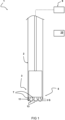
- Fig. 1 shows a schematic diagram of an embodiment of an electro-pulse drilling system 1.
- the drilling system 1 comprises a controller 10 configured for operating the electro-pulse drilling system.
- the system 1 comprises a drill head 3 with an end portion 5, wherein at least two electrodes 7 are arranged at the end portion 5 of the drill head 3.
- the system 1 further includes an actuation system 9 configured for moving the drill head adjacent to the surface 11 to be broken up.
- the system 1 also includes a voltage generator configured for applying a voltage between the electrodes 7 resulting in one or more electric discharges between the electrodes 7, the one or more discharges resulting in one or more electric arcs 13 for breaking up the surface 11.
- a distancing unit is provided for providing a gap distance D between the at least two electrodes 7 of the drill head 3 and the surface 11 during generation of the one or more electric arcs 13.
- the controller acts as the distancing unit, maintaining the gap distance D by means of controlling the actuation system 9.
- a member such as a spacer is provided for maintaining a (minimum) gap distance G between the electrodes 7 of the drill head 3 and the surface 11.
- the drill head 3 is positioned in a drill hole 2.
- the voltage generated (not shown in this figure) is separated from the drill head 3.
- the voltage generated is attached to or integrated in the drill head.
- the drill head 3 and the voltage generator form a unitary device, directly coupled to each other.
- the drill head 3 and the voltage generator are separated and can be positioned remotely with respect to each other, for instance coupled by means of wiring.
- the drill head 3 and the voltage generator are separated such as to allow movement with respect to each other. Many types of arrangements are possible.
- the front end of the drill head 3 is not necessarily a flat face containing electrodes 7 extending therefrom.
- the front end may only include protruding electrodes (e.g. rods with electrode end portions). Between the protruding electrodes 7, sufficient spacing may be provided to as to allow debris to be evacuated by means of flushing. Additionally, a gap distance G is provided between the electrodes 7 and the surface 11 being drilled, such that a significantly improved electro-pulse drilling can be achieved.
- sensors are arranged at at least one of: at least one of the at least two electrodes or the voltage generator, for determining a value indicative of the pulse duration.
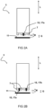
- Fig. 2a, 2b show a schematic diagram of an embodiment of a drill head 3.
- a gap distance G is provided between the electrodes of the drill head 3 and the surface 11 during generation of the one or more electric arcs.
- a mechanical spacing unit 15 is provided for mechanically distancing the electrodes of the drill head and the surface to be broken up.
- the spacing units 15 are protruding from an end face of the drill head 3.
- the spacing unit 15 comprises one finger 17a, which is arranged centrally on the drill head 3, for providing a minimum distance M between the electrodes of the drill head 3 and the surface 11 when the drill head 3 approaches said surface 11.
- the spacing unit 15 comprises two fingers 17a, 17b extending from the drill head towards the surface 11.
- a minimum distance may be provided by means of the two fingers 17a, 17b.
- the fingers 17a, 17b may better guarantee a minimum distance M.
- the gap distance G is maintained within a predetermined range.
- the minimal gap distance is at least 1 millimeter. Larger minimal gap distances are also possible, such as at least 2 millimeter and/or at least 3 millimeters may also be employed.
- the gap distance G may provide for an advantageous space or opening between the at least two electrodes 7 of the drill head 3 and the surface 11 to broken up.
- the at least two electrodes 7 may be positioned such as to face the surface 11, and a minimum distance is provided such as to prevent direct contact between the surface 11 (e.g. rock in the bore hole) and any of the at least two electrodes 7.
- all electrodes 7 arranged on the drill head 3 may be spaced apart from the surface 11 during generation of the electric arcs. In this way, the arcs can be better guaranteed to travel into the surface, such as to have improved fragmentation of the surface material during drilling. It can be prevented that any one of the electrodes at which the arc is generated contacts the surface.
- the gap distance G can be understood as the smallest distance between any one of the electrodes of the drill head and the surface. With other words, the gap distance G may be seen as the distance between the part of the surface being closest to any one of the at least two electrodes and said any one of the at least two electrodes. In some examples, the gap distance G is measured in a longitudinal direction L of the drill head 3.
- the drill head 3 is lowered in the drill/bore hole during the drilling/boring process.
- the drill head 3 may be actuated by means of an actuation unit for inducing movement of the drill head 3.
- the drill head 3 can descend aided by its own weight.
- the speed in which the drill head is drilling/boring (cf. speed of lowering) can be determined by means of cables and/or flushing pipes. In some examples, the speed is adjusted for keeping the gap distance G between the electrodes 7 of the drill head 3 and the surface 11 within a desired predetermined range.
- a self-regulating system may be achieved, wherein initially a minimum distance is maintained, for example falling within a predetermined range.
- the gap distance between the electrodes of the electro-pulse drill head and the surface may be kept at a minimum distance of 1 millimeter, avoiding any contact between the electrodes and the surface.
- the distance may be increased, since some pieces of the surface are broken off and debris are flushed away.
- the system may automatically lower the drill head, for example at a constant pace or periodically (intermittently), whilst maintaining a predetermined minimum distance.
- the minimum distance may for instance be achieved by a mechanical spacing unit, providing the ability for a simple control system. However, additionally or alternatively, it is also envisaged to provide for a control system for maintaining at least the minimum distance. Such control system may also be configured to keep the distance/separation between the electrodes of the drill head and the surface within a predetermined range. In some cases, the predetermined range may be adjusted, for instance taking into account properties of the drilling fluid, the surface, the pulse actuation, etc.
- Fig. 3 shows a schematic diagram of an embodiment of a drill head 3.
- the drill head 3 may have a first set of electrodes 7a and a second set of electrodes 7b, the first set of electrodes 7a used with a first polarity (e.g. positive), and the second set of electrodes 7b used with a second polarity (e.g. negative), i.e. opposite polarity.
- the drill head has ten electrodes 7a, 7b arranged at the end portion 5.
- Each polarity (positive, negative) has five electrodes.
- the electrodes may have various shapes, dimensions and arrangements on the drill head 3.
- the first set of electrodes 7a has electrodes which are smaller than the electrodes in the second set of electrodes 7b.
- At least a subset of electrodes is arranged along a periphery of the drill head.
- at least one electrode has a ring shape.
- a first ring may form one or more positive electrodes and a second ring may form one or more negative electrodes, wherein the first ring is inside the second ring, or vice versa.
- the electrodes 7a, 7b may have various forms and shapes and many alternative arrangements are envisaged.
- the drill head 3 may have various dimensions.
- a gap distance may be provide such as to have no contact. Contact, and thus no gap distance (i.e. a gap distance equal to zero), may have a significant detrimental effect on the efficiency of the electro-pulse boring/drilling.
- Fig. 4 shows a schematic diagram of an embodiment of a discharge tube 20 of a voltage generator.
- a first spark 21 and a second spark 23 are arranged within the discharge tube.
- the sparks 21, 23 may be arranged in a tube 22.
- an optical sensor 25 is arranged at the discharge tube 20 of the voltage generator.
- the sensory data retrieved by the optical sensor provides an indication of the property of the generated arc between the at least two electrodes 7 of the drill head 3.
- the pulse duration i.e. length of time
- the controller 10 can determine whether the one or more electric arcs have travelled into the surface to be broken up, based on the value indicative of the length of time.
- the controller 10 can be configured to calculate whether the length of time of the one or more electric arcs is smaller than a threshold value, wherein one or more operational parameters of the actuation system 9 are adjusted for changing the gap distance G between the drill head and the surface when the length of time of said one or more electric arcs is larger than the threshold value.
- optical sensor 25 clearly has an advantage over other sensors, which would require much more effort and extra measures to make it function properly in the aggressive electromagnetic interference environment during generation of the one or more electric arcs, for example by extensive shielding against electromagnetic interference.
- debris e.g. rock fragments resulting from the drilling process
- the drill head 3 may be completely submerged in a drilling fluid (e.g. liquid such as water), which can make optical detection more difficult. Additionally, as a result of the relatively rough conditions, the optical sensor may be more prone to damage.
- arranging the optical sensor at the voltage generator may provide important benefits.
- optical sensors are arranged at the drill head and the voltage generator. By performing optical measurements at the generator and the drill head it is also possible to make the results even more accurate.
- Fig. 5 shows a schematic diagram of an embodiment of a discharge tube 20, similar to the example shown in fig. 4 .
- the discharge tube 20 may be transparent, allowing the optical sensor 25 to be arranged outside of the discharge tube 20. In this way, a very robust and reliable sensory arrangement can be obtained.
- Fig. 6 shows a schematic diagram of an embodiment of a drill head 3 comprising an optical sensor 25.
- the optical sensor 25 is integrated in the drill head 3. Such an integrated design can increase the reliability and robustness.
- the optical sensor 25 is arranged at the end portion 5 of the drill head 3 facing the surface 11.
- the optical sensor 25 is employed for directly sensing light induced by the one or more arcs generated between the electrodes 7 during the electro-pulse drilling. Based on the sensed light, an indication of the pulse duration can for example be determined or calculated.
- a permittivity of the drilling fluid F is larger than a permittivity of the surface 11 (e.g. rock or mineral). In this way, it can be avoided that the electric arc travels only through the drilling fluid (not going through the surface).
- the drilling fluid F is chosen such that its permittivity is at least 5 times larger than that of the material of the surface, preferably at least 10 times larger, even more preferably at least 20 times larger.
- a water based liquid F can be a polarized liquid, resulting in higher permittivity.
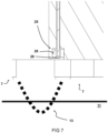
- Fig. 7 shows a schematic diagram of an embodiment of an optical sensor 25 integrated in the drill head 3.
- the optical sensor 25 has a housing 26 and is arranged adjacent the electrodes 7 with its sensory portion 28 facing a region where arcs are generated between electrodes.
- a plurality of optical sensors 25 may be used in some examples. In this way, for example, the pulse duration can be more accurately determined, whilst providing a more reliable configuration.
- the invention enables improved control during electro-pulse drilling.
- the gap distance between the electrodes and the surface to be broken up is within the predetermined range, the surface may be more efficiently broken up in pieces. Larger debris may be obtained, which can thereby result in higher boring/drilling speeds achievable by means of the drill head.
- the distance is too small, for instance smaller than 500 micrometer, for instance due to contact between at least one electrode of the at least two electrodes of the drill head and the surface, then the surface may break too slowly as a result of the generated electric pulses/sparks.
- the system is configured to provide a gap distance/interspace between the at least two electrodes of the drill head and the surface during generation of the one or more electric arcs.
- Fig. 8a, 8b show a schematic diagram of an embodiment of drill head 3.
- a voltage generator 30 is integrated within the drill head 3.
- the voltage generator 30 is distanced from the drill head.
- the distance between the voltage generator 30 and the drill head 3 may be variable in this example, for example the distance may be increased when the drill head 3 is lowered further in the bore hole.
- the voltage generator 30 and the drill head 3 may be coupled by means of a coupling member 40.
- an optical sensor is employed at the voltage generator 30 and/or at the drill head 3.
- the operation of the optical sensor is not sensitive to electromagnetic interference resulting from the operation of the electro-pulse system. This may be an important advantage with respect to other types of sensors, such as for example electronic sensors.
- Fig. 9 shows a schematic diagram of a method 100 of drilling by means of a drill head with an end portion, wherein at least two electrodes are arranged at the end portion.
- a first step 101 the drill head is moved adjacent to a surface to be broken up by means of an actuation system.
- a gap distance is provided between the at least two electrodes of the drill head and the surface.
- a voltage is applied between the electrodes, by means of a voltage generator, resulting in one or more electric discharges between the electrodes, the one or more discharges resulting in one or more electric arcs for breaking up the surface, wherein the gap distance is maintained at least during generation of the one or more electric arcs.
- the gap distance may be actively, e.g. by controlling the actuation, or passively, e.g. by providing one or more mechanical spacing units, maintained
- electro-pulse drilling may also be understood as electrical-pulse drilling, electrical arc drilling, electro-crushing drilling, pulsed arc plasma drilling, pulsating arc drilling, plasma arc drilling, plasma pulse drilling, plasma pulse geo-drilling, etc.
- the term “drilling” along with its derivatives, may be replaced with “boring” and vice versa.
- the term can be interpreted as an action of making a hole, cutting or making an indentation or the like, in some surface or material.
- drilling or boring may imply that pieces of the surface or material are broken up and are removed from the drilling zone during the drilling process.
- the method may include computer implemented steps. All above mentioned steps can be computer implemented steps.
- Embodiments may comprise computer apparatus, wherein processes performed in computer apparatus.
- the invention also extends to computer programs, particularly computer programs on or in a carrier, adapted for putting the invention into practice.
- the program may be in the form of source or object code or in any other form suitable for use in the implementation of the processes according to the invention.
- the carrier may be any entity or device capable of carrying the program.
- the carrier may comprise a storage medium, such as a ROM, for example a semiconductor ROM or hard disk.
- the carrier may be a transmissible carrier such as an electrical or optical signal which may be conveyed via electrical or optical cable or by radio or other means, e.g. via the internet or cloud.
- Some embodiments may be implemented, for example, using a machine or tangible computer-readable medium or article which may store an instruction or a set of instructions that, if executed by a machine, may cause the machine to perform a method and/or operations in accordance with the embodiments.
- Various embodiments may be implemented using hardware elements, software elements, or a combination of both.
- hardware elements may include processors, microprocessors, circuits, application specific integrated circuits (ASIC), programmable logic devices (PLD), digital signal processors (DSP), field programmable gate array (FPGA), logic gates, registers, semiconductor device, microchips, chip sets, et cetera.
- software may include software components, programs, applications, computer programs, application programs, system programs, machine programs, operating system software, mobile apps, middleware, firmware, software modules, routines, subroutines, functions, computer implemented methods, procedures, software interfaces, application program interfaces (API), methods, instruction sets, computing code, computer code, et cetera.
- API application program interfaces
- any reference signs placed between parentheses shall not be construed as limiting the claim.
- the word 'comprising' does not exclude the presence of other features or steps than those listed in a claim.
- the words 'a' and 'an' shall not be construed as limited to 'only one', but instead are used to mean 'at least one', and do not exclude a plurality.
- the mere fact that certain measures are recited in mutually different claims does not indicate that a combination of these measures cannot be used to an advantage.
Landscapes
- Engineering & Computer Science (AREA)
- Mining & Mineral Resources (AREA)
- Life Sciences & Earth Sciences (AREA)
- Geology (AREA)
- General Life Sciences & Earth Sciences (AREA)
- Geochemistry & Mineralogy (AREA)
- Physics & Mathematics (AREA)
- Environmental & Geological Engineering (AREA)
- Fluid Mechanics (AREA)
- Earth Drilling (AREA)
- Electrical Discharge Machining, Electrochemical Machining, And Combined Machining (AREA)
Claims (11)
- Verfahren zum Bohren mittels eines Bohrkopfes mit einem Endabschnitt, wobei mindestens zwei Elektroden an dem Endabschnitt angeordnet sind, wobei das Verfahren umfasst:Bewegen des Bohrkopfes mittels eines Betätigungssystems in die Nähe einer zu brechenden Oberfläche,Anlegen einer Spannung zwischen den Elektroden mittels eines Spannungsgenerators, was zu einer oder mehreren elektrischen Entladungen zwischen den Elektroden führt, wobei die eine oder mehreren Entladungen zu einem oder mehreren Lichtbögen zum Aufbrechen der Oberfläche führen, und wobei ein minimaler Spaltabstand zwischen den mindestens zwei Elektroden des Bohrkopfes und der Oberfläche während der Erzeugung des einen oder der mehreren Lichtbögen vorgesehen ist,Messen mindestens eines Wertes, der eine Eigenschaft des erzeugten Lichtbogens oder der erzeugten Lichtbögen anzeigt, mittels eines Sensormesssystems, undSteuern eines oder mehrerer Betriebsparameter des Betätigungssystems mittels eines Steuersystems, um den minimalen Spaltabstand zwischen dem Bohrkopf und der Oberfläche auf der Grundlage des mindestens einen Wertes anzupassen.
- Verfahren nach Anspruch 1, wobei das Sensormesssystem einen optischen Sensor umfasst, der so konfiguriert ist, dass er einen Wert misst, der eine Zeitdauer des einen oder der mehreren Lichtbögen anzeigt.
- Verfahren nach Anspruch 2, wobei der optische Sensor am Spannungsgenerator angeordnet ist.
- Verfahren nach Anspruch 2 oder 3, wobei der optische Sensor am Bohrkopf angeordnet ist.
- Verfahren nach Anspruch 2, 3 oder 4, wobei der Wert, der die Zeitdauer des einen oder der mehreren Lichtbögen angibt, dem zurückgelegten Weg des einen oder der mehreren Lichtbögen zugeordnet ist.
- Verfahren nach einem der vorhergehenden Ansprüche 2 bis 5, wobei das Steuersystem so konfiguriert ist, dass es auf der Grundlage des Wertes, der die Zeitdauer angibt, bestimmt, ob der eine oder die mehreren Lichtbögen in die aufzubrechende Oberfläche eingedrungen sind.
- Verfahren nach einem der vorhergehenden Ansprüche 2 bis 6, wobei das Steuersystem so konfiguriert ist, dass es feststellt, ob die Zeitdauer des einen oder der mehreren Lichtbögen kleiner als ein Schwellenwert ist, wobei ein oder mehrere Betriebsparameter des Betätigungssystems eingestellt werden, um den minimalen Spaltabstand zwischen dem Bohrkopf und der Oberfläche zu ändern, wenn die Zeitdauer des einen oder der mehreren Lichtbögen größer als der Schwellenwert ist.
- Verfahren nach einem der vorhergehenden Ansprüche, wobei der minimale Spaltabstand zwischen 1 und 30 Millimeter, bevorzugter zwischen 2 und 10 Millimeter, noch bevorzugter zwischen 2 und 5 Millimeter gehalten wird.
- Verfahren nach einem der vorhergehenden Ansprüche, wobei eine Abstandseinheit vorgesehen ist, um die mindestens zwei Elektroden des Bohrkopfes und die aufzubrechende Oberfläche mechanisch zu distanzieren.
- Verfahren nach Anspruch 9, wobei die Abstandseinheit so konfiguriert ist, dass sie einen Mindestabstand zwischen dem Bohrkopf und der zu brechenden Oberfläche einhält.
- System zur Durchführung gepulster Bohrvorgänge, wobei das System Folgendes umfasst:einen Bohrkopf mit einem Endabschnitt, wobei an dem Endabschnitt mindestens zwei Elektroden angeordnet sind;ein Betätigungssystem, das so konfiguriert ist, dass es den Bohrkopf in die Nähe der zu brechenden Oberfläche bewegt;einen Spannungsgenerator, der so konfiguriert ist, dass er eine Spannung zwischen den Elektroden anlegt, die zu einer oder mehreren elektrischen Entladungen zwischen den Elektroden führt, wobei die eine oder mehreren Entladungen zu einem oder mehreren Lichtbögen zum Aufbrechen der Oberfläche führen;eine Abstandseinheit zur Bereitstellung eines Mindestabstands zwischen den mindestens zwei Elektroden des Bohrkopfs und der Oberfläche während der Erzeugung des einen oder der mehreren Lichtbögen;ein Sensormesssystem zur Messung mindestens eines Wertes, der eine Eigenschaft des oder der erzeugten Lichtbögen anzeigt; undein Steuersystem, das so konfiguriert ist, dass es einen oder mehrere Betriebsparameter des Betätigungssystems so steuert, dass der minimale Spaltabstand zwischen dem Bohrkopf und der Oberfläche auf der Grundlage des mindestens einen Wertes eingestellt wird.
Priority Applications (4)
| Application Number | Priority Date | Filing Date | Title |
|---|---|---|---|
| ES21199973T ES3028245T3 (en) | 2021-09-29 | 2021-09-29 | A method and system for electro-pulse drilling |
| EP21199973.5A EP4159970B1 (de) | 2021-09-29 | 2021-09-29 | Verfahren und system zum elektroimpulsbohren |
| CN202280066287.0A CN118103580A (zh) | 2021-09-29 | 2022-09-28 | 一种电脉冲钻孔的方法和系统 |
| PCT/EP2022/076959 WO2023052412A1 (en) | 2021-09-29 | 2022-09-28 | A method and system for electro-pulse drilling |
Applications Claiming Priority (1)
| Application Number | Priority Date | Filing Date | Title |
|---|---|---|---|
| EP21199973.5A EP4159970B1 (de) | 2021-09-29 | 2021-09-29 | Verfahren und system zum elektroimpulsbohren |
Publications (3)
| Publication Number | Publication Date |
|---|---|
| EP4159970A1 EP4159970A1 (de) | 2023-04-05 |
| EP4159970B1 true EP4159970B1 (de) | 2025-05-14 |
| EP4159970C0 EP4159970C0 (de) | 2025-05-14 |
Family
ID=78211838
Family Applications (1)
| Application Number | Title | Priority Date | Filing Date |
|---|---|---|---|
| EP21199973.5A Active EP4159970B1 (de) | 2021-09-29 | 2021-09-29 | Verfahren und system zum elektroimpulsbohren |
Country Status (4)
| Country | Link |
|---|---|
| EP (1) | EP4159970B1 (de) |
| CN (1) | CN118103580A (de) |
| ES (1) | ES3028245T3 (de) |
| WO (1) | WO2023052412A1 (de) |
Families Citing this family (4)
| Publication number | Priority date | Publication date | Assignee | Title |
|---|---|---|---|---|
| WO2024232790A1 (en) * | 2023-05-09 | 2024-11-14 | Epiroc Rock Drills Aktiebolag | High voltage electro pulse rock drilling |
| WO2025073367A1 (en) * | 2023-10-05 | 2025-04-10 | Vito Nv | A high voltage pulse generator a method of operating a high voltage pulse generator |
| WO2025080169A1 (en) * | 2023-10-10 | 2025-04-17 | Epiroc Rock Drills Ab | A pulsed power drilling system, drill rig and method for controlling pulse generation |
| EP4545747A1 (de) * | 2023-10-24 | 2025-04-30 | Vito NV | Bestimmung der effizienz eines bohrprozesses unter verwendung eines marx-generators |
Family Cites Families (5)
| Publication number | Priority date | Publication date | Assignee | Title |
|---|---|---|---|---|
| JPH09314421A (ja) * | 1996-05-30 | 1997-12-09 | Toyota Motor Corp | 放電加工による曲がり穴加工方法及びその装置 |
| NO322323B2 (no) * | 2003-12-01 | 2016-09-13 | Unodrill As | Fremgangsmåte og anordning for grunnboring |
| SK500582012A3 (sk) * | 2012-12-17 | 2014-08-05 | Ga Drilling, A. S. | Multimodálne rozrušovanie horniny termickým účinkom a systém na jeho vykonávanie |
| US10577767B2 (en) * | 2018-02-20 | 2020-03-03 | Petram Technologies, Inc. | In-situ piling and anchor shaping using plasma blasting |
| CA3118091A1 (en) * | 2018-10-30 | 2020-05-07 | The Texas A&M University System | Systems and methods for forming a subterranean borehole |
-
2021
- 2021-09-29 EP EP21199973.5A patent/EP4159970B1/de active Active
- 2021-09-29 ES ES21199973T patent/ES3028245T3/es active Active
-
2022
- 2022-09-28 CN CN202280066287.0A patent/CN118103580A/zh active Pending
- 2022-09-28 WO PCT/EP2022/076959 patent/WO2023052412A1/en not_active Ceased
Also Published As
| Publication number | Publication date |
|---|---|
| CN118103580A (zh) | 2024-05-28 |
| EP4159970A1 (de) | 2023-04-05 |
| EP4159970C0 (de) | 2025-05-14 |
| ES3028245T3 (en) | 2025-06-18 |
| WO2023052412A1 (en) | 2023-04-06 |
Similar Documents
| Publication | Publication Date | Title |
|---|---|---|
| EP4159970B1 (de) | Verfahren und system zum elektroimpulsbohren | |
| US11629587B2 (en) | Systems and methods for dielectric mapping during pulsed-power drilling | |
| AU2008213158B2 (en) | Assembly for drilling and logging, method for drilling and logging and device for electro pulse drilling | |
| EP1474587B1 (de) | Verfahren zum plasma-bohren | |
| CN101371098B (zh) | 测量设备、岩石破碎设备和测量应力波的方法 | |
| US20180283168A1 (en) | Methods and systems to identify a plurality of flood fronts at different azimuthal positions relative to a borehole | |
| EP3500724B1 (de) | Akustische stimulation | |
| US20170204668A1 (en) | Electric pulse drilling apparatus with hole cleaning passages | |
| Che et al. | Numerical analysis and experimental research on hard rock fragmentation by high voltage pulse discharge | |
| US20220307323A1 (en) | Formation evaluation based on pulse power electrode discharge measurements | |
| US11466517B2 (en) | Determining formation characteristics using reference sensor responses recorded during pulsed drilling | |
| US11555353B2 (en) | Pulse power drilling control | |
| US8619503B2 (en) | Sparker type wellbore seismic energy source having controllable depth independent frequency | |
| US9903977B2 (en) | Radiation induced conductivity of oil based mud around pads of electrical imaging tools | |
| WO2017099773A1 (en) | Downhole field ionization neutron generator | |
| RU131503U1 (ru) | Устройство для генерирования упругих импульсов в гидросфере горизонтальной скважины | |
| Peng et al. | Effect of the electrode spacing on dynamic fracture behavior of red sandstone under high-voltage pulse discharge | |
| US8511421B1 (en) | Acoustic sources | |
| Walsh et al. | Electropulse stimulation of rock: Insights from grain-scale experimental studies and numerical models | |
| Ushakov et al. | Regularities of rock destruction in the process of ED-drilling of wells | |
| CA2981594A1 (en) | Apparatus and method of focused in-situ electrical heating of hydrocarbon bearing formations | |
| Kúdelčìk et al. | Surface Discharge Over Rock in Transformer Oil | |
| Bai et al. | An experimental device for measuring the internal temperature and pressure of rock for rock breaking by pulsed discharge in petroleum exploitation | |
| WO2025087948A1 (en) | Determining the efficiency of a drilling process performed by the use of a marx generator | |
| RU2569905C1 (ru) | Устройство для измерения интенсивности радиоактивного излучения горных пород в скважине |
Legal Events
| Date | Code | Title | Description |
|---|---|---|---|
| PUAI | Public reference made under article 153(3) epc to a published international application that has entered the european phase |
Free format text: ORIGINAL CODE: 0009012 |
|
| STAA | Information on the status of an ep patent application or granted ep patent |
Free format text: STATUS: THE APPLICATION HAS BEEN PUBLISHED |
|
| AK | Designated contracting states |
Kind code of ref document: A1 Designated state(s): AL AT BE BG CH CY CZ DE DK EE ES FI FR GB GR HR HU IE IS IT LI LT LU LV MC MK MT NL NO PL PT RO RS SE SI SK SM TR |
|
| STAA | Information on the status of an ep patent application or granted ep patent |
Free format text: STATUS: REQUEST FOR EXAMINATION WAS MADE |
|
| 17P | Request for examination filed |
Effective date: 20231004 |
|
| RBV | Designated contracting states (corrected) |
Designated state(s): AL AT BE BG CH CY CZ DE DK EE ES FI FR GB GR HR HU IE IS IT LI LT LU LV MC MK MT NL NO PL PT RO RS SE SI SK SM TR |
|
| GRAP | Despatch of communication of intention to grant a patent |
Free format text: ORIGINAL CODE: EPIDOSNIGR1 |
|
| STAA | Information on the status of an ep patent application or granted ep patent |
Free format text: STATUS: GRANT OF PATENT IS INTENDED |
|
| INTG | Intention to grant announced |
Effective date: 20241206 |
|
| GRAS | Grant fee paid |
Free format text: ORIGINAL CODE: EPIDOSNIGR3 |
|
| GRAA | (expected) grant |
Free format text: ORIGINAL CODE: 0009210 |
|
| STAA | Information on the status of an ep patent application or granted ep patent |
Free format text: STATUS: THE PATENT HAS BEEN GRANTED |
|
| AK | Designated contracting states |
Kind code of ref document: B1 Designated state(s): AL AT BE BG CH CY CZ DE DK EE ES FI FR GB GR HR HU IE IS IT LI LT LU LV MC MK MT NL NO PL PT RO RS SE SI SK SM TR |
|
| REG | Reference to a national code |
Ref country code: GB Ref legal event code: FG4D |
|
| REG | Reference to a national code |
Ref country code: CH Ref legal event code: EP |
|
| REG | Reference to a national code |
Ref country code: IE Ref legal event code: FG4D |
|
| REG | Reference to a national code |
Ref country code: DE Ref legal event code: R096 Ref document number: 602021030722 Country of ref document: DE |
|
| REG | Reference to a national code |
Ref country code: ES Ref legal event code: FG2A Ref document number: 3028245 Country of ref document: ES Kind code of ref document: T3 Effective date: 20250618 |
|
| U01 | Request for unitary effect filed |
Effective date: 20250523 |
|
| U07 | Unitary effect registered |
Designated state(s): AT BE BG DE DK EE FI FR IT LT LU LV MT NL PT RO SE SI Effective date: 20250602 |
|
| U20 | Renewal fee for the european patent with unitary effect paid |
Year of fee payment: 5 Effective date: 20250820 |
|
| REG | Reference to a national code |
Ref country code: CH Ref legal event code: U11 Free format text: ST27 STATUS EVENT CODE: U-0-0-U10-U11 (AS PROVIDED BY THE NATIONAL OFFICE) Effective date: 20251001 |
|
| PG25 | Lapsed in a contracting state [announced via postgrant information from national office to epo] |
Ref country code: GR Free format text: LAPSE BECAUSE OF FAILURE TO SUBMIT A TRANSLATION OF THE DESCRIPTION OR TO PAY THE FEE WITHIN THE PRESCRIBED TIME-LIMIT Effective date: 20250815 |
|
| PGFP | Annual fee paid to national office [announced via postgrant information from national office to epo] |
Ref country code: NO Payment date: 20250825 Year of fee payment: 5 |
|
| PG25 | Lapsed in a contracting state [announced via postgrant information from national office to epo] |
Ref country code: PL Free format text: LAPSE BECAUSE OF FAILURE TO SUBMIT A TRANSLATION OF THE DESCRIPTION OR TO PAY THE FEE WITHIN THE PRESCRIBED TIME-LIMIT Effective date: 20250514 |
|
| PGFP | Annual fee paid to national office [announced via postgrant information from national office to epo] |
Ref country code: GB Payment date: 20250827 Year of fee payment: 5 |
|
| PG25 | Lapsed in a contracting state [announced via postgrant information from national office to epo] |
Ref country code: HR Free format text: LAPSE BECAUSE OF FAILURE TO SUBMIT A TRANSLATION OF THE DESCRIPTION OR TO PAY THE FEE WITHIN THE PRESCRIBED TIME-LIMIT Effective date: 20250514 |
|
| PG25 | Lapsed in a contracting state [announced via postgrant information from national office to epo] |
Ref country code: RS Free format text: LAPSE BECAUSE OF FAILURE TO SUBMIT A TRANSLATION OF THE DESCRIPTION OR TO PAY THE FEE WITHIN THE PRESCRIBED TIME-LIMIT Effective date: 20250814 |
|
| PG25 | Lapsed in a contracting state [announced via postgrant information from national office to epo] |
Ref country code: IS Free format text: LAPSE BECAUSE OF FAILURE TO SUBMIT A TRANSLATION OF THE DESCRIPTION OR TO PAY THE FEE WITHIN THE PRESCRIBED TIME-LIMIT Effective date: 20250914 |