EP4159831A1 - Torrefaction unit and method - Google Patents
Torrefaction unit and method Download PDFInfo
- Publication number
- EP4159831A1 EP4159831A1 EP21200579.7A EP21200579A EP4159831A1 EP 4159831 A1 EP4159831 A1 EP 4159831A1 EP 21200579 A EP21200579 A EP 21200579A EP 4159831 A1 EP4159831 A1 EP 4159831A1
- Authority
- EP
- European Patent Office
- Prior art keywords
- torrefaction
- water
- steam
- multiple hearth
- syngas
- Prior art date
- Legal status (The legal status is an assumption and is not a legal conclusion. Google has not performed a legal analysis and makes no representation as to the accuracy of the status listed.)
- Pending
Links
- 238000000034 method Methods 0.000 title claims description 20
- XLYOFNOQVPJJNP-UHFFFAOYSA-N water Substances O XLYOFNOQVPJJNP-UHFFFAOYSA-N 0.000 claims abstract description 103
- 229910001868 water Inorganic materials 0.000 claims abstract description 103
- 238000007254 oxidation reaction Methods 0.000 claims abstract description 35
- 230000003647 oxidation Effects 0.000 claims abstract description 32
- 239000013529 heat transfer fluid Substances 0.000 claims abstract description 31
- 239000000463 material Substances 0.000 claims abstract description 28
- 238000010438 heat treatment Methods 0.000 claims abstract description 25
- 239000002028 Biomass Substances 0.000 claims abstract description 12
- 239000007789 gas Substances 0.000 claims description 31
- QVGXLLKOCUKJST-UHFFFAOYSA-N atomic oxygen Chemical compound [O] QVGXLLKOCUKJST-UHFFFAOYSA-N 0.000 claims description 15
- 239000001301 oxygen Substances 0.000 claims description 15
- 229910052760 oxygen Inorganic materials 0.000 claims description 15
- 238000001704 evaporation Methods 0.000 claims description 5
- 239000012530 fluid Substances 0.000 claims description 5
- 230000008020 evaporation Effects 0.000 claims description 4
- 239000010813 municipal solid waste Substances 0.000 abstract description 4
- 239000007788 liquid Substances 0.000 description 11
- CURLTUGMZLYLDI-UHFFFAOYSA-N Carbon dioxide Chemical compound O=C=O CURLTUGMZLYLDI-UHFFFAOYSA-N 0.000 description 8
- 239000000446 fuel Substances 0.000 description 8
- 239000007787 solid Substances 0.000 description 8
- OKKJLVBELUTLKV-UHFFFAOYSA-N Methanol Chemical compound OC OKKJLVBELUTLKV-UHFFFAOYSA-N 0.000 description 6
- 238000010791 quenching Methods 0.000 description 6
- 230000000171 quenching effect Effects 0.000 description 6
- 239000002699 waste material Substances 0.000 description 6
- QGZKDVFQNNGYKY-UHFFFAOYSA-N Ammonia Chemical compound N QGZKDVFQNNGYKY-UHFFFAOYSA-N 0.000 description 4
- UGFAIRIUMAVXCW-UHFFFAOYSA-N Carbon monoxide Chemical compound [O+]#[C-] UGFAIRIUMAVXCW-UHFFFAOYSA-N 0.000 description 4
- 229910002092 carbon dioxide Inorganic materials 0.000 description 4
- 239000001569 carbon dioxide Substances 0.000 description 4
- 229910002091 carbon monoxide Inorganic materials 0.000 description 4
- 230000001143 conditioned effect Effects 0.000 description 4
- 229930195733 hydrocarbon Natural products 0.000 description 4
- 150000002430 hydrocarbons Chemical class 0.000 description 4
- 230000001590 oxidative effect Effects 0.000 description 4
- 238000005260 corrosion Methods 0.000 description 3
- 230000007797 corrosion Effects 0.000 description 3
- 238000004880 explosion Methods 0.000 description 3
- 239000000126 substance Substances 0.000 description 3
- 239000011269 tar Substances 0.000 description 3
- 239000003039 volatile agent Substances 0.000 description 3
- 229910021529 ammonia Inorganic materials 0.000 description 2
- 150000001875 compounds Chemical class 0.000 description 2
- 239000000203 mixture Substances 0.000 description 2
- 239000008188 pellet Substances 0.000 description 2
- 238000011144 upstream manufacturing Methods 0.000 description 2
- MYMOFIZGZYHOMD-UHFFFAOYSA-N Dioxygen Chemical compound O=O MYMOFIZGZYHOMD-UHFFFAOYSA-N 0.000 description 1
- UFHFLCQGNIYNRP-UHFFFAOYSA-N Hydrogen Chemical compound [H][H] UFHFLCQGNIYNRP-UHFFFAOYSA-N 0.000 description 1
- 238000006243 chemical reaction Methods 0.000 description 1
- 238000001816 cooling Methods 0.000 description 1
- 230000008878 coupling Effects 0.000 description 1
- 238000010168 coupling process Methods 0.000 description 1
- 238000005859 coupling reaction Methods 0.000 description 1
- 230000001419 dependent effect Effects 0.000 description 1
- 239000000835 fiber Substances 0.000 description 1
- 239000013056 hazardous product Substances 0.000 description 1
- 239000001257 hydrogen Substances 0.000 description 1
- 229910052739 hydrogen Inorganic materials 0.000 description 1
- 239000002440 industrial waste Substances 0.000 description 1
- VNWKTOKETHGBQD-UHFFFAOYSA-N methane Chemical compound C VNWKTOKETHGBQD-UHFFFAOYSA-N 0.000 description 1
- 238000005191 phase separation Methods 0.000 description 1
- 230000001105 regulatory effect Effects 0.000 description 1
- 238000000926 separation method Methods 0.000 description 1
- 239000010802 sludge Substances 0.000 description 1
- 239000011343 solid material Substances 0.000 description 1
- 230000002194 synthesizing effect Effects 0.000 description 1
- 239000010913 used oil Substances 0.000 description 1
- 239000002023 wood Substances 0.000 description 1
Images
Classifications
-
- C—CHEMISTRY; METALLURGY
- C10—PETROLEUM, GAS OR COKE INDUSTRIES; TECHNICAL GASES CONTAINING CARBON MONOXIDE; FUELS; LUBRICANTS; PEAT
- C10B—DESTRUCTIVE DISTILLATION OF CARBONACEOUS MATERIALS FOR PRODUCTION OF GAS, COKE, TAR, OR SIMILAR MATERIALS
- C10B53/00—Destructive distillation, specially adapted for particular solid raw materials or solid raw materials in special form
- C10B53/02—Destructive distillation, specially adapted for particular solid raw materials or solid raw materials in special form of cellulose-containing material
-
- C—CHEMISTRY; METALLURGY
- C10—PETROLEUM, GAS OR COKE INDUSTRIES; TECHNICAL GASES CONTAINING CARBON MONOXIDE; FUELS; LUBRICANTS; PEAT
- C10B—DESTRUCTIVE DISTILLATION OF CARBONACEOUS MATERIALS FOR PRODUCTION OF GAS, COKE, TAR, OR SIMILAR MATERIALS
- C10B47/00—Destructive distillation of solid carbonaceous materials with indirect heating, e.g. by external combustion
- C10B47/28—Other processes
- C10B47/32—Other processes in ovens with mechanical conveying means
- C10B47/34—Other processes in ovens with mechanical conveying means with rotary scraping devices
- C10B47/36—Other processes in ovens with mechanical conveying means with rotary scraping devices in multi-stage ovens
-
- C—CHEMISTRY; METALLURGY
- C10—PETROLEUM, GAS OR COKE INDUSTRIES; TECHNICAL GASES CONTAINING CARBON MONOXIDE; FUELS; LUBRICANTS; PEAT
- C10B—DESTRUCTIVE DISTILLATION OF CARBONACEOUS MATERIALS FOR PRODUCTION OF GAS, COKE, TAR, OR SIMILAR MATERIALS
- C10B57/00—Other carbonising or coking processes; Features of destructive distillation processes in general
- C10B57/02—Multi-step carbonising or coking processes
-
- C—CHEMISTRY; METALLURGY
- C10—PETROLEUM, GAS OR COKE INDUSTRIES; TECHNICAL GASES CONTAINING CARBON MONOXIDE; FUELS; LUBRICANTS; PEAT
- C10B—DESTRUCTIVE DISTILLATION OF CARBONACEOUS MATERIALS FOR PRODUCTION OF GAS, COKE, TAR, OR SIMILAR MATERIALS
- C10B57/00—Other carbonising or coking processes; Features of destructive distillation processes in general
- C10B57/14—Features of low-temperature carbonising processes
-
- C—CHEMISTRY; METALLURGY
- C10—PETROLEUM, GAS OR COKE INDUSTRIES; TECHNICAL GASES CONTAINING CARBON MONOXIDE; FUELS; LUBRICANTS; PEAT
- C10K—PURIFYING OR MODIFYING THE CHEMICAL COMPOSITION OF COMBUSTIBLE GASES CONTAINING CARBON MONOXIDE
- C10K3/00—Modifying the chemical composition of combustible gases containing carbon monoxide to produce an improved fuel, e.g. one of different calorific value, which may be free from carbon monoxide
- C10K3/001—Modifying the chemical composition of combustible gases containing carbon monoxide to produce an improved fuel, e.g. one of different calorific value, which may be free from carbon monoxide by thermal treatment
- C10K3/003—Reducing the tar content
- C10K3/005—Reducing the tar content by partial oxidation
-
- C—CHEMISTRY; METALLURGY
- C10—PETROLEUM, GAS OR COKE INDUSTRIES; TECHNICAL GASES CONTAINING CARBON MONOXIDE; FUELS; LUBRICANTS; PEAT
- C10L—FUELS NOT OTHERWISE PROVIDED FOR; NATURAL GAS; SYNTHETIC NATURAL GAS OBTAINED BY PROCESSES NOT COVERED BY SUBCLASSES C10G, C10K; LIQUEFIED PETROLEUM GAS; ADDING MATERIALS TO FUELS OR FIRES TO REDUCE SMOKE OR UNDESIRABLE DEPOSITS OR TO FACILITATE SOOT REMOVAL; FIRELIGHTERS
- C10L9/00—Treating solid fuels to improve their combustion
- C10L9/08—Treating solid fuels to improve their combustion by heat treatments, e.g. calcining
- C10L9/083—Torrefaction
-
- C—CHEMISTRY; METALLURGY
- C10—PETROLEUM, GAS OR COKE INDUSTRIES; TECHNICAL GASES CONTAINING CARBON MONOXIDE; FUELS; LUBRICANTS; PEAT
- C10L—FUELS NOT OTHERWISE PROVIDED FOR; NATURAL GAS; SYNTHETIC NATURAL GAS OBTAINED BY PROCESSES NOT COVERED BY SUBCLASSES C10G, C10K; LIQUEFIED PETROLEUM GAS; ADDING MATERIALS TO FUELS OR FIRES TO REDUCE SMOKE OR UNDESIRABLE DEPOSITS OR TO FACILITATE SOOT REMOVAL; FIRELIGHTERS
- C10L2290/00—Fuel preparation or upgrading, processes or apparatus therefore, comprising specific process steps or apparatus units
- C10L2290/04—Gasification
-
- C—CHEMISTRY; METALLURGY
- C10—PETROLEUM, GAS OR COKE INDUSTRIES; TECHNICAL GASES CONTAINING CARBON MONOXIDE; FUELS; LUBRICANTS; PEAT
- C10L—FUELS NOT OTHERWISE PROVIDED FOR; NATURAL GAS; SYNTHETIC NATURAL GAS OBTAINED BY PROCESSES NOT COVERED BY SUBCLASSES C10G, C10K; LIQUEFIED PETROLEUM GAS; ADDING MATERIALS TO FUELS OR FIRES TO REDUCE SMOKE OR UNDESIRABLE DEPOSITS OR TO FACILITATE SOOT REMOVAL; FIRELIGHTERS
- C10L2290/00—Fuel preparation or upgrading, processes or apparatus therefore, comprising specific process steps or apparatus units
- C10L2290/06—Heat exchange, direct or indirect
-
- C—CHEMISTRY; METALLURGY
- C10—PETROLEUM, GAS OR COKE INDUSTRIES; TECHNICAL GASES CONTAINING CARBON MONOXIDE; FUELS; LUBRICANTS; PEAT
- C10L—FUELS NOT OTHERWISE PROVIDED FOR; NATURAL GAS; SYNTHETIC NATURAL GAS OBTAINED BY PROCESSES NOT COVERED BY SUBCLASSES C10G, C10K; LIQUEFIED PETROLEUM GAS; ADDING MATERIALS TO FUELS OR FIRES TO REDUCE SMOKE OR UNDESIRABLE DEPOSITS OR TO FACILITATE SOOT REMOVAL; FIRELIGHTERS
- C10L2290/00—Fuel preparation or upgrading, processes or apparatus therefore, comprising specific process steps or apparatus units
- C10L2290/58—Control or regulation of the fuel preparation of upgrading process
-
- Y—GENERAL TAGGING OF NEW TECHNOLOGICAL DEVELOPMENTS; GENERAL TAGGING OF CROSS-SECTIONAL TECHNOLOGIES SPANNING OVER SEVERAL SECTIONS OF THE IPC; TECHNICAL SUBJECTS COVERED BY FORMER USPC CROSS-REFERENCE ART COLLECTIONS [XRACs] AND DIGESTS
- Y02—TECHNOLOGIES OR APPLICATIONS FOR MITIGATION OR ADAPTATION AGAINST CLIMATE CHANGE
- Y02E—REDUCTION OF GREENHOUSE GAS [GHG] EMISSIONS, RELATED TO ENERGY GENERATION, TRANSMISSION OR DISTRIBUTION
- Y02E50/00—Technologies for the production of fuel of non-fossil origin
- Y02E50/10—Biofuels, e.g. bio-diesel
Definitions
- Subject matter of the present invention is a torrefaction unit as well as a method for torrefaction of biomass containing material.
- the invention is particularly applicable to the torrefaction of waste, in particular municipal solid waste, preferably in the form of solid recovered fuel pellets.
- Torrefaction is known in processing municipal wastes, e.g. from the unpublished European patent application EP20204801.3 . Torrefaction is understood as a process in which material such as waste is heated to temperatures of up to 300°C in the absence of oxygen The products of this torrefaction are a torrefaction gas comprising water, carbon monoxide, carbon dioxide, smaller oxygenated hydrocarbons and tars, and the charred solids remaining from the waste.
- the heating value of the volatiles is converted into heat in an oxidizing unit.
- the residual heat generated in this oxidizing unit can be used for heating the torrefaction process.
- This is known to be done using an oil such as a thermal oil as a heat transfer medium.
- This has certain disadvantages, such as the necessity to provide a large inventory of the used oil and the general use of a hazardous material which needs specific measures to avoid leakage into the environment.
- the coupling of the torrefaction furnace and the oxidizing unit creates further issues.
- the torrefaction unit for the torrefaction of a material comprising biomass comprises at least one multiple hearth furnace, said multiple hearth furnace comprising a heating system which can be flown through by a heat transfer fluid, wherein the heating system is connected to a water circuit by which water is heatable and conveyable through the heating system.
- multiple hearth furnace is understood as a furnace having several hearths or kilns superimposed on each other, whereas the material is applied at the top of the multiple hearth furnace and is moved through the multiple hearth furnace by rotating conveying elements. The material is moved from the top to the bottom of the multiple hearth furnace while openings allow the transfer from an upper hearth to a respective lower hearth.
- the material comprising biomass in the following designated as the material, comprises preferably municipal solid waste, solid recovered fuel pellets, industrial waste and/or biomass, e.g. wood, plant fibers, sludge etc.
- the water can be provided as liquid and/or steam, preferably as liquid.
- the operating temperature of the torrefaction furnace is usually in the range of 200°C to 300°C, preferably in the range of 280°C to 320°C.
- the temperature of the water when entering the heating system of the multiple hearth furnace is preferably controlled to be slightly above the operating temperature of the torrefaction furnace, preferably about 30°C to 50°C above the operating temperature.
- the flow of the water through the heating system is preferably controlled such that the temperature of the water when leaving the heating system of the multiple hearth furnace is 15°C to 25°C below the temperature of the water when entering the heating system.
- the use of water as heat transfer fluid has the advantage that in case of a leak only water is emitted into the furnace.
- the hot water can be used preferably from an existing water/steam cycle.
- the torrefaction unit further comprises a partial oxidation reactor including a burning chamber being connected to the at least one multiple hearth furnace for the partial oxidation of torrefaction gas with oxygen creating a syngas.
- the torrefaction gas is the gaseous product of the torrefaction and comprises water, carbon monoxide, carbon dioxide, hydrocarbons, oxygenated hydrocarbons and/or tar, depending on the material which undergoes torrefaction.
- the torrefaction gas is processed in the partial oxidation independently of the processing of the charred solids being the further product of the torrefaction.
- the partial oxidation of the torrefaction gas generates syngas, comprising at least hydrogen and carbon monoxide, and, depending on the conditions under which the reaction takes place, carbon dioxide and moisture.
- the syngas is preferably used to synthesize further substances, e.g. synthetic natural gas, ammonia and methanol. This allows to synthesize substances based on waste or biomass.
- the syngas is preferably quenched with cooler syngas. The abrupt reduction of the temperature in the syngas results in any solids or melted solids present in the syngas are solidified and can be extracted from the process.
- a single partial oxidation reactor is connected to at least two multiple hearth furnaces.
- a hot water source such as a steam drum as a source for thermal energy
- thermal energy generated in the partial oxidation in the partial oxidation reactor to the steam drum it is possible to combine at least two multiple hearth furnaces with a single partial oxidation reactor.
- the torrefaction unit further comprises a steam drum having a steam space and a water space, wherein the water circuit is connected to the water space of the steam drum.
- a steam drum having a steam space and a water space, wherein the water circuit is connected to the water space of the steam drum.
- the water space and the steam space of the steam drum are in fluid connection with an evaporator which is heatable by syngas generated by partial oxidation of torrefaction gas.
- an evaporator which is heatable by syngas generated by partial oxidation of torrefaction gas.
- This allows to guide already hot water from the water space of the steam drum to the evaporator to at least in part evaporate the water to create steam or a mixture of steam and liquid water which can be guided to the steam space of the steam drum for phase separation.
- the thermal energy of the syngas can be used to evaporate the water creating steam for the steam drum.
- the steam space of the steam drum is in fluid connection with a superheater which is heatable by syngas generated by partial oxidation of torrefaction gas.
- a superheater which is heatable by syngas generated by partial oxidation of torrefaction gas.
- the evaporator is situated upstream of the superheater such that the thermal energy of the syngas entering the superheater is already lower compared to the thermal energy of the syngas entering the evaporator.
- a method for the torrefaction of a material comprising biomass wherein the material is heated to a torrefaction temperature in at least one multiple hearth furnace, wherein the atmosphere in the at least one multiple hearth furnace is controlled to provide a substoichiometric amount of oxygen, preferably to be a virtually oxygen free atmosphere, wherein the at least one multiple hearth furnace is heated by a heat transfer fluid comprising water.
- the term virtually oxygen-free atmosphere is to be understood as an atmosphere having a volume content of oxygen of less than 1 vol.-%, being than the lower explosion limit.
- the atmosphere in the at least one multiple hearth furnace is controlled to be below the lower explosion limit.
- the torrefaction temperature is preferably within the range of 200°C to 300°C, preferably in the range of 280°C to 300°C.
- the heat transfer fluid is preferably liquid water and/or steam, preferably liquid water, preferably water being conditioned for reducing corrosion to be used in drum boilers, in particular high pressure drum boilers.
- the at least one multiple hearth furnace is solely heated by the heat transfer fluid. No further fuel is introduced into the multiple hearth furnace beside the material to be torrefied.
- the use of water as a heat transfer fluid overcomes the problems associated with the use of thermal oil as a heat transfer fluid.
- torrefaction gas is generated by the torrefaction of the material, said torrefaction gas being partially oxidized to generate a syngas.
- the torrefaction gas is partially oxidized, in particular separately from the possible further treatment of the charred material being the other product of the torrefaction process.
- the partial oxidization resulting in a syngas allows in particular to use chemical compounds of waste or biomass to synthesize further chemical compounds.
- the torrefaction gas of at least two multiple hearth furnaces is partially oxidized in a single partial oxidation reactor.
- the use of water as a heat transfer medium and in particular the use of an existing water/steam cycle as a source of the water used as the heat transfer fluid reduces the complexity of the control of the torrefaction furnace and the partial oxidation reactor significantly, as thermal energy generated during the partial oxidization is not directly used to heat the torrefaction furnace but is at most used to heat the water in the water/steam cycle, thus decoupling the control of the partial oxidation reactor from the control of the torrefaction furnace.
- water originating from a respective boiler (boiler water) is used as the heat transfer medium.
- the heat transfer fluid comprises water taken from a steam drum.
- the respective water is preferably conditioned as boiler water to reduce corrosion in the boiler and the respective water/steam cycle.
- a steam drum is understood in this document as a reservoir of liquid water and steam usually disposed at the top end of a boiler and its water tubes.
- the steam drum stores the steam generated e.g. in the boiler in a steam space while liquid water is stored in a water space.
- the steam drum acts as a phase separator for the steam and liquid water mixture.
- the use of a steam drum as a source for hot water allows to retrofit a respective torrefaction furnace in an existing plant having a boiler.
- the heat transfer fluid is guided in a water circuit from the steam drum through a heating system of the at least one multiple hearth furnace and back to the steam drum.
- a heating system of the at least one multiple hearth furnace and back to the steam drum.
- This allows an easy control of the torrefaction temperature in the at least one multiple hearth furnace. Further, this allows to retrofit a torrefaction unit to an existing plant having a boiler with a steam drum.
- torrefaction gas is generated by the torrefaction of the material, said torrefaction gas being partially oxidized to generate a syngas, the syngas being used to at least in part evaporate water provided from a water space of said steam drum, wherein the at least partly evaporated water is provided to a steam space of said steam drum after evaporation.
- the heat transfer from the syngas to the water is an indirect heat transfer performed in an evaporator. This allows to use a part of the thermal energy of the syngas for the evaporation.
- torrefaction gas is generated by the torrefaction of the material, said torrefaction gas being partially oxidized to generate a syngas, the syngas being used to superheat steam provided from a steam space of the steam drum.
- This allows a use of a part of the thermal energy of the syngas for superheating steam which is taken from the steam space of the steam drum and is then guided to at least one steam consumer.
- the use of thermal energy of the syngas for evaporating water and for superheating steam are used in combination as this allows to use a significant amount of the thermal energy for heating usable media (i.e. water and steam).
- the superheating happens downstream of the evaporation.
- the atmosphere in the at least one multiple hearth furnace is controlled to provide an oxygen content of less than 1 vol.-% .
- an atmosphere being virtually free of oxygen is kept in the multiple hearth furnaces to allow a torrefaction without oxidation processes of the material.
- the atmosphere in the at least one multiple hearth furnace is controlled to be below the lower explosion limit.
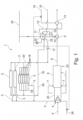
- Fig. 1 displays a torrefaction unit 1.
- the torrefaction unit 1 comprises in this example three multiple hearth furnaces 2 two of which are only displayed very schematically.
- a material comprising biomass is torrefied, i.e. heated within in an atmosphere which is substoichiometric regarding an oxidation of the material at temperatures of up to 300°C and is preferably virtually free of oxygen, i.e. is having an oxygen content of less than 1 vol.-%.
- Each multiple hearth furnace 2 comprises several hearths 18. The material is applied to the uppermost hearth 18 and is conveyed around each hearth 18 and downwards from hearth 18 to hearth 18.
- the multiple hearth furnace 2 is heated to a torrefaction temperature, e.g. to about 300°C. This is performed by a heating system 19.
- the heating system 19 comprises ducts through which hot water is conveyed to heat the multiple hearth furnace 2 indirectly.
- the water is provided to the heating system 19 from a water circuit 20.
- the water is preferably boiler water, i.e. conditioned to reduce corrosion in a boiler water/steam cycle.
- a torrefaction gas 3 comprising the volatiles.
- the torrefaction gas 3 is provided via a burner 4 to burning chamber 25 for partial oxidization with oxygen from an oxygen comprising gas 5, preferably pure oxygen.
- Auxiliary fuel 26 can be provided to the burner 4 as well, in particular for starting up.
- a control line is depicted as a dashed line by which valves regulating the flow of auxiliary fuel 26 and/or superheated steam 14, in particular based on the pressure in a steam space 22 of the steam drum 11, are controllable.
- syngas which is quenched with cooler quenching syngas 7 in a quenching chamber 6 resulting in a cooled syngas 8 which is provided to an evaporator 9. Solids or melted solids in the syngas are solidified due to the quenching process and are preferably removed from the syngas.
- the cooled syngas 8 after quenching has a temperature of e.g. 730°C to 770°C.
- a part of the thermal energy of the cooled syngas 8 is used to at least partly evaporate water 10.
- Said water 10 is provided from a water space 21 of a steam drum 11 and is returned to a steam space 22 of the steam drum 11.
- Steam 12 from the steam space 22 of the steam drum 11 is guided via a superheater 13 to superheat the steam 12 using thermal energy from the cooled syngas 8 generating superheated steam 14 which can be used in at least one steam consumer (not shown) in which the steam is used e.g. to drive a turbine, to feed a dryer etc.
- the superheated steam 14 has a temperature of e.g.
- Boiler feedwater 15 can be used to provide the steam drum 11 with liquid water. Boiler feedwater 15 has preferably a conductivity of less than 5 ⁇ S/cm [mikrosiemens per centimeter]. Boiler feedwater 15 is preferably conditioned for anti-corrosive properties, preferably by providing ammonia to the boiler feedwater 15.
- the steam drum 11 is part of the water circuit 20.
- Heat transfer fluid 16 comprising hot boiler water from the water space 21 of the steam drum 11 is conveyed by a pump 17 through the ducts of the water circuit 20 to heating system 19 of at least one multiple hearth furnace 2.
- the steam drum 11 is controlled such that the heat transfer fluid 16 is taken from the water space 21 as liquid and has preferably a temperature from 335°C to 345°C when exiting the steam drum 11.
- the heat transfer fluid 16 is guided through respective heating ducts of the heating system 19 in the walls of the at least one multiple hearth furnace 2, preferably in the ceilings of respective stages of the multiple hearth furnaces 2, to heat the interior of the multiple hearth furnace 2 to the torrefaction temperature.
- the heat transfer fluid 16 After having heated the multiple hearth furnace 2 the heat transfer fluid 16 is returned to the steam drum 11 via the water circuit 20. Usually, the temperature of the heat transfer fluid 16 downstream the multiple hearth furnace 2 is reduced by 15°C to 25°C compared to the temperature of the heat transfer fluid 16 upstream of the multiple hearth furnace 2.
- the steam space 22 of the steam drum 11 is connectable to a steam grid 24. This allows to use steam from an external source to start-up the steam drum 11, if necessary.
- the torrefaction unit 1 comprises at least one multiple hearth furnace 2 which is heated by a heat transfer fluid 16 comprising hot water taken form a water space 21 of a steam drum 11.
- the heat transfer fluid 16 is guided through a water circuit 20 to a heating system 19 of the at least one multiple hearth furnace 2.
- This means the multiple hearth furnace 2 is heated to a torrefaction temperature indirectly by the use of hot water as heat transfer fluid 16.
- the torrefaction gas 3 created by the torrefaction of material comprising biomass such as municipal solid waste is preferably partially oxidized in a partial oxidation reactor 23 for creating syngas.
- a part of the thermal energy of the syngas is used in an evaporator 9 and/or a superheater 13 to heat water and/or steam and/or to evaporate water.
- the evaporated water is preferably guided to a steam space 22 of the steam drum 11 and can, thus, be used to heat the heat transfer fluid 16.
- the partial oxidation reactor 23 and the temperature of the heat transfer fluid 16 can be controlled independently allowing to one single partial oxidation reactor 23 for at least two multiple hearth furnaces 2.
Landscapes
- Chemical & Material Sciences (AREA)
- Engineering & Computer Science (AREA)
- Oil, Petroleum & Natural Gas (AREA)
- Organic Chemistry (AREA)
- Materials Engineering (AREA)
- Combustion & Propulsion (AREA)
- Physics & Mathematics (AREA)
- Thermal Sciences (AREA)
- Chemical Kinetics & Catalysis (AREA)
- General Chemical & Material Sciences (AREA)
- Processing Of Solid Wastes (AREA)
- Diaphragms For Electromechanical Transducers (AREA)
Abstract
Description
- Subject matter of the present invention is a torrefaction unit as well as a method for torrefaction of biomass containing material. The invention is particularly applicable to the torrefaction of waste, in particular municipal solid waste, preferably in the form of solid recovered fuel pellets.
- Torrefaction is known in processing municipal wastes, e.g. from the unpublished European patent application
EP20204801.3 - Usually, the heating value of the volatiles is converted into heat in an oxidizing unit. The residual heat generated in this oxidizing unit can be used for heating the torrefaction process. This is known to be done using an oil such as a thermal oil as a heat transfer medium. This has certain disadvantages, such as the necessity to provide a large inventory of the used oil and the general use of a hazardous material which needs specific measures to avoid leakage into the environment. Furthermore, the coupling of the torrefaction furnace and the oxidizing unit creates further issues. The control of this combined system has been found to be complex, furthermore, to be prepared for all possible circumstances it is necessary to provide auxiliary fuel to the oxidizing chamber in case of a shortage of heat and to provide a cooler for cooling the oil in case of a surplus of heat.
- Based on this it is an object of the present invention to overcome the disadvantages known from prior art at least in part. This is solved by the features of the independent claims. The respective dependent claims are directed to advantageous embodiments of the invention.
- The torrefaction unit for the torrefaction of a material comprising biomass according to the present invention comprises at least one multiple hearth furnace, said multiple hearth furnace comprising a heating system which can be flown through by a heat transfer fluid, wherein the heating system is connected to a water circuit by which water is heatable and conveyable through the heating system.
- The term multiple hearth furnace is understood as a furnace having several hearths or kilns superimposed on each other, whereas the material is applied at the top of the multiple hearth furnace and is moved through the multiple hearth furnace by rotating conveying elements. The material is moved from the top to the bottom of the multiple hearth furnace while openings allow the transfer from an upper hearth to a respective lower hearth.
- The material comprising biomass, in the following designated as the material, comprises preferably municipal solid waste, solid recovered fuel pellets, industrial waste and/or biomass, e.g. wood, plant fibers, sludge etc.
- The water can be provided as liquid and/or steam, preferably as liquid. The operating temperature of the torrefaction furnace is usually in the range of 200°C to 300°C, preferably in the range of 280°C to 320°C. The temperature of the water when entering the heating system of the multiple hearth furnace is preferably controlled to be slightly above the operating temperature of the torrefaction furnace, preferably about 30°C to 50°C above the operating temperature. The flow of the water through the heating system is preferably controlled such that the temperature of the water when leaving the heating system of the multiple hearth furnace is 15°C to 25°C below the temperature of the water when entering the heating system. The use of water as heat transfer fluid has the advantage that in case of a leak only water is emitted into the furnace. Furthermore, the hot water can be used preferably from an existing water/steam cycle. This reduces the apparative expense and allows to extend an existing facility by a torrefaction unit according to the present invention without the necessity to install a thermal oil cycle including a large reservoir and the respective safety measures to avoid leakage to the environment. Furthermore, the option to connect to an existing steam/water cycle, e.g. including a steam drum, reduces the control effort to control the temperature in the heating system of the multiple hearth furnace significantly.
- Preferably, the torrefaction unit further comprises a partial oxidation reactor including a burning chamber being connected to the at least one multiple hearth furnace for the partial oxidation of torrefaction gas with oxygen creating a syngas. The torrefaction gas is the gaseous product of the torrefaction and comprises water, carbon monoxide, carbon dioxide, hydrocarbons, oxygenated hydrocarbons and/or tar, depending on the material which undergoes torrefaction. The torrefaction gas is processed in the partial oxidation independently of the processing of the charred solids being the further product of the torrefaction. The partial oxidation of the torrefaction gas generates syngas, comprising at least hydrogen and carbon monoxide, and, depending on the conditions under which the reaction takes place, carbon dioxide and moisture.
- The syngas is preferably used to synthesize further substances, e.g. synthetic natural gas, ammonia and methanol. This allows to synthesize substances based on waste or biomass. The syngas is preferably quenched with cooler syngas. The abrupt reduction of the temperature in the syngas results in any solids or melted solids present in the syngas are solidified and can be extracted from the process.
- Preferably, a single partial oxidation reactor is connected to at least two multiple hearth furnaces. As based on the invention it is not necessary to directly use the thermal energy generated in the partial oxidation reactor to heat the multiple hearth furnace but to use a hot water source such as a steam drum as a source for thermal energy, while, preferably, providing thermal energy generated in the partial oxidation in the partial oxidation reactor to the steam drum instead it is possible to combine at least two multiple hearth furnaces with a single partial oxidation reactor. With the preferred embodiment it is, thus, possible to control the at least two multiple hearth furnaces separately from the single partial oxidation reactor. This reduces invest for hardware significantly as e.g. no additional cooler or a burner being providable with auxiliary fuel is necessary as well as the footprint of the necessary equipment.
- Preferably, the torrefaction unit further comprises a steam drum having a steam space and a water space, wherein the water circuit is connected to the water space of the steam drum. Thus, it is easily possible to provide liquid hot water from the water space to the at least one multiple hearth furnace. Hot water can be easily be generated using the respective boiler of which the steam drum is a part. The use of a steam drum as a source for hot water allows to easily retrofit the torrefaction unit into existing plants having a boiler with a steam drum.
- Preferably, the water space and the steam space of the steam drum are in fluid connection with an evaporator which is heatable by syngas generated by partial oxidation of torrefaction gas. This allows to guide already hot water from the water space of the steam drum to the evaporator to at least in part evaporate the water to create steam or a mixture of steam and liquid water which can be guided to the steam space of the steam drum for phase separation. Simultaneously, the thermal energy of the syngas can be used to evaporate the water creating steam for the steam drum.
- Preferably, the steam space of the steam drum is in fluid connection with a superheater which is heatable by syngas generated by partial oxidation of torrefaction gas. This allows to further use the thermal energy of the syngas. Preferably, the evaporator is situated upstream of the superheater such that the thermal energy of the syngas entering the superheater is already lower compared to the thermal energy of the syngas entering the evaporator.
- According to a further aspect of the present invention a method for the torrefaction of a material comprising biomass is proposed, wherein the material is heated to a torrefaction temperature in at least one multiple hearth furnace, wherein the atmosphere in the at least one multiple hearth furnace is controlled to provide a substoichiometric amount of oxygen, preferably to be a virtually oxygen free atmosphere, wherein the at least one multiple hearth furnace is heated by a heat transfer fluid comprising water.
- The term virtually oxygen-free atmosphere is to be understood as an atmosphere having a volume content of oxygen of less than 1 vol.-%, being than the lower explosion limit. Preferably, the atmosphere in the at least one multiple hearth furnace is controlled to be below the lower explosion limit. The torrefaction temperature is preferably within the range of 200°C to 300°C, preferably in the range of 280°C to 300°C. The heat transfer fluid is preferably liquid water and/or steam, preferably liquid water, preferably water being conditioned for reducing corrosion to be used in drum boilers, in particular high pressure drum boilers. The at least one multiple hearth furnace is solely heated by the heat transfer fluid. No further fuel is introduced into the multiple hearth furnace beside the material to be torrefied. The use of water as a heat transfer fluid overcomes the problems associated with the use of thermal oil as a heat transfer fluid.
- Preferably, torrefaction gas is generated by the torrefaction of the material, said torrefaction gas being partially oxidized to generate a syngas. Preferably, solely the torrefaction gas is partially oxidized, in particular separately from the possible further treatment of the charred material being the other product of the torrefaction process. The partial oxidization resulting in a syngas allows in particular to use chemical compounds of waste or biomass to synthesize further chemical compounds.
- Preferably, the torrefaction gas of at least two multiple hearth furnaces is partially oxidized in a single partial oxidation reactor. The use of water as a heat transfer medium and in particular the use of an existing water/steam cycle as a source of the water used as the heat transfer fluid reduces the complexity of the control of the torrefaction furnace and the partial oxidation reactor significantly, as thermal energy generated during the partial oxidization is not directly used to heat the torrefaction furnace but is at most used to heat the water in the water/steam cycle, thus decoupling the control of the partial oxidation reactor from the control of the torrefaction furnace. Preferably, water originating from a respective boiler (boiler water) is used as the heat transfer medium.
- Preferably, the heat transfer fluid comprises water taken from a steam drum. The respective water is preferably conditioned as boiler water to reduce corrosion in the boiler and the respective water/steam cycle. A steam drum is understood in this document as a reservoir of liquid water and steam usually disposed at the top end of a boiler and its water tubes. The steam drum stores the steam generated e.g. in the boiler in a steam space while liquid water is stored in a water space. The steam drum acts as a phase separator for the steam and liquid water mixture. The use of a steam drum as a source for hot water allows to retrofit a respective torrefaction furnace in an existing plant having a boiler.
- Preferably, the heat transfer fluid is guided in a water circuit from the steam drum through a heating system of the at least one multiple hearth furnace and back to the steam drum. This allows an easy control of the torrefaction temperature in the at least one multiple hearth furnace. Further, this allows to retrofit a torrefaction unit to an existing plant having a boiler with a steam drum.
- Preferably, torrefaction gas is generated by the torrefaction of the material, said torrefaction gas being partially oxidized to generate a syngas, the syngas being used to at least in part evaporate water provided from a water space of said steam drum, wherein the at least partly evaporated water is provided to a steam space of said steam drum after evaporation. The heat transfer from the syngas to the water is an indirect heat transfer performed in an evaporator. This allows to use a part of the thermal energy of the syngas for the evaporation. As the thermal energy is transferred not directly to the multiple hearth furnace but to a steam drum from which the heat transfer fluid is taken this allows a separation of the control of the partial oxidation generating the syngas on the one hand and of the at least one multiple hearth furnace on the other hand.
- Preferably, torrefaction gas is generated by the torrefaction of the material, said torrefaction gas being partially oxidized to generate a syngas, the syngas being used to superheat steam provided from a steam space of the steam drum. This allows a use of a part of the thermal energy of the syngas for superheating steam which is taken from the steam space of the steam drum and is then guided to at least one steam consumer. Preferably, the use of thermal energy of the syngas for evaporating water and for superheating steam are used in combination as this allows to use a significant amount of the thermal energy for heating usable media (i.e. water and steam). Preferably, with respect to the flow of syngas the superheating happens downstream of the evaporation.
- Preferably, the atmosphere in the at least one multiple hearth furnace is controlled to provide an oxygen content of less than 1 vol.-% .This means that an atmosphere being virtually free of oxygen is kept in the multiple hearth furnaces to allow a torrefaction without oxidation processes of the material. Thus, the atmosphere in the at least one multiple hearth furnace is controlled to be below the lower explosion limit.
- It should be noted that the individual features specified in the claims may be combined with one another in any desired technologically reasonable manner and form further embodiments of the invention. The specification, in particular taken together with the figures, explains the invention further and specifies particularly preferred embodiments of the invention. Particularly preferred variants of the invention and the technical field will now be explained in more detail with reference to the enclosed figures. It should be noted that the exemplary embodiment shown in the figures is not intended to restrict the invention. The figures are schematic and may not be to scale. The single figure displays:
- Fig. 1
- a process scheme of the torrefaction unit.
-
Fig. 1 displays a torrefaction unit 1. The torrefaction unit 1 comprises in this example threemultiple hearth furnaces 2 two of which are only displayed very schematically. In each multiple hearth furnace 2 a material comprising biomass is torrefied, i.e. heated within in an atmosphere which is substoichiometric regarding an oxidation of the material at temperatures of up to 300°C and is preferably virtually free of oxygen, i.e. is having an oxygen content of less than 1 vol.-%. Eachmultiple hearth furnace 2 comprisesseveral hearths 18. The material is applied to theuppermost hearth 18 and is conveyed around eachhearth 18 and downwards fromhearth 18 tohearth 18. Themultiple hearth furnace 2 is heated to a torrefaction temperature, e.g. to about 300°C. This is performed by aheating system 19. Theheating system 19 comprises ducts through which hot water is conveyed to heat themultiple hearth furnace 2 indirectly. The water is provided to theheating system 19 from awater circuit 20. The water is preferably boiler water, i.e. conditioned to reduce corrosion in a boiler water/steam cycle. - By the torrefaction, volatiles of the material are released comprising water, carbon monoxide, carbon dioxide, smaller oxygenated hydrocarbons and tars. The remaining solid material taken from of the
multiple hearth furnace 2 is improved regarding its grindability and can be used in different processes. A further product of the torrefaction process is, thus, atorrefaction gas 3 comprising the volatiles. Preferably, thetorrefaction gas 3 is provided via aburner 4 to burningchamber 25 for partial oxidization with oxygen from anoxygen comprising gas 5, preferably pure oxygen.Auxiliary fuel 26 can be provided to theburner 4 as well, in particular for starting up. A control line is depicted as a dashed line by which valves regulating the flow ofauxiliary fuel 26 and/orsuperheated steam 14, in particular based on the pressure in asteam space 22 of thesteam drum 11, are controllable. - One product of this partial oxidation is syngas which is quenched with
cooler quenching syngas 7 in aquenching chamber 6 resulting in a cooledsyngas 8 which is provided to anevaporator 9. Solids or melted solids in the syngas are solidified due to the quenching process and are preferably removed from the syngas. - The cooled
syngas 8 after quenching has a temperature of e.g. 730°C to 770°C. A part of the thermal energy of the cooledsyngas 8 is used to at least partly evaporatewater 10. Saidwater 10 is provided from awater space 21 of asteam drum 11 and is returned to asteam space 22 of thesteam drum 11.Steam 12 from thesteam space 22 of thesteam drum 11 is guided via asuperheater 13 to superheat thesteam 12 using thermal energy from the cooledsyngas 8 generatingsuperheated steam 14 which can be used in at least one steam consumer (not shown) in which the steam is used e.g. to drive a turbine, to feed a dryer etc. Thesuperheated steam 14 has a temperature of e.g. 340°C to 360°C and a pressure of 130 bar to 150 bar. Downstream of thesuperheater 13 the cooledsyngas 8 can be further used e.g. for synthesizing longer chemical molecules, e.g. methanol or the like.Boiler feedwater 15 can be used to provide thesteam drum 11 with liquid water.Boiler feedwater 15 has preferably a conductivity of less than 5 µS/cm [mikrosiemens per centimeter].Boiler feedwater 15 is preferably conditioned for anti-corrosive properties, preferably by providing ammonia to theboiler feedwater 15. - The
steam drum 11 is part of thewater circuit 20.Heat transfer fluid 16 comprising hot boiler water from thewater space 21 of thesteam drum 11 is conveyed by apump 17 through the ducts of thewater circuit 20 toheating system 19 of at least onemultiple hearth furnace 2. Thesteam drum 11 is controlled such that theheat transfer fluid 16 is taken from thewater space 21 as liquid and has preferably a temperature from 335°C to 345°C when exiting thesteam drum 11. Theheat transfer fluid 16 is guided through respective heating ducts of theheating system 19 in the walls of the at least onemultiple hearth furnace 2, preferably in the ceilings of respective stages of themultiple hearth furnaces 2, to heat the interior of themultiple hearth furnace 2 to the torrefaction temperature. After having heated themultiple hearth furnace 2 theheat transfer fluid 16 is returned to thesteam drum 11 via thewater circuit 20. Usually, the temperature of theheat transfer fluid 16 downstream themultiple hearth furnace 2 is reduced by 15°C to 25°C compared to the temperature of theheat transfer fluid 16 upstream of themultiple hearth furnace 2. - Preferably, the
steam space 22 of thesteam drum 11 is connectable to asteam grid 24. This allows to use steam from an external source to start-up thesteam drum 11, if necessary. - The torrefaction unit 1 comprises at least one
multiple hearth furnace 2 which is heated by aheat transfer fluid 16 comprising hot water taken form awater space 21 of asteam drum 11. Theheat transfer fluid 16 is guided through awater circuit 20 to aheating system 19 of the at least onemultiple hearth furnace 2. This means themultiple hearth furnace 2 is heated to a torrefaction temperature indirectly by the use of hot water asheat transfer fluid 16. This is environmentally advantageous. Thetorrefaction gas 3 created by the torrefaction of material comprising biomass such as municipal solid waste is preferably partially oxidized in apartial oxidation reactor 23 for creating syngas. Preferably, a part of the thermal energy of the syngas is used in anevaporator 9 and/or asuperheater 13 to heat water and/or steam and/or to evaporate water. The evaporated water is preferably guided to asteam space 22 of thesteam drum 11 and can, thus, be used to heat theheat transfer fluid 16. Thepartial oxidation reactor 23 and the temperature of theheat transfer fluid 16 can be controlled independently allowing to one singlepartial oxidation reactor 23 for at least twomultiple hearth furnaces 2. -
- 1
- torrefaction unit
- 2
- multiple hearth furnace
- 3
- torrefaction gas
- 4
- burner
- 5
- oxygen comprising gas
- 6
- quenching chamber
- 7
- quenching syngas
- 8
- cooled syngas
- 9
- evaporator
- 10
- water
- 11
- steam drum
- 12
- steam
- 13
- superheater
- 14
- superheated steam
- 15
- boiler feedwater
- 16
- heat transfer fluid
- 17
- pump
- 18
- hearth
- 19
- heating system
- 20
- water circuit
- 21
- water space
- 22
- steam space
- 23
- partial oxidation reactor
- 24
- steam grid
- 25
- burning chamber
- 26
- auxiliary fuel
Claims (14)
- Torrefaction unit (1) for the torrefaction of a material comprising biomass, comprising at least one multiple hearth furnace (2), said multiple hearth furnace (2) comprising a heating system (19) which can be flown through by a heat transfer fluid (16), characterized in that the heating system (19) is connected to a water circuit (20) by which water is heatable and conveyable through the heating system (19).
- Torrefaction unit (1) according to claim 1, further comprising a partial oxidation reactor (23) including a burning chamber (4) being connected to the at least one multiple hearth furnace (2) for the partial oxidation of torrefaction gas (3) with oxygen creating a syngas (8).
- Torrefaction unit (1) according to claim 2, wherein a single partial oxidation reactor (23) is connected to at least two multiple hearth furnaces (2).
- Torrefaction unit (1) according to one of the preceding claims, further comprising a steam drum (11) having a steam space (22) and a water space (21), wherein the water circuit (20) is connected to the water space (21) of the steam drum (11).
- Torrefaction unit (1) according to claim 4, wherein the water space (21) and the steam space (22) of the steam drum (11) are in fluid connection with an evaporator (9) which is heatable by syngas (8) generated by partial oxidation of torrefaction gas (3).
- Torrefaction unit (1) according to claim 4 or 5, wherein the steam space (22) of the steam drum (11) is in fluid connection with a superheater (13) which is heatable by syngas (8) generated by partial oxidation of torrefaction gas (3).
- Method for the torrefaction of a material comprising biomass, wherein the material is heated to a torrefaction temperature in at least one multiple hearth furnace (2), wherein the atmosphere in the at least one multiple hearth furnace (2) is controlled to provide a substoichiometric amount of oxygen, characterized in that the at least one multiple hearth furnace (2) is heated by a heat transfer (16) fluid comprising water.
- Method according to claim 7, wherein torrefaction gas (3) is generated by the torrefaction of the material, said torrefaction gas (3) being partially oxidized to generate a syngas (8).
- Method according to claim 8, wherein the torrefaction gas (3) of at least two multiple hearth furnaces (2) is partially oxidized in a single partial oxidation reactor (23).
- Method according to one of claims 7 to 9, wherein the heat transfer fluid (16) comprises water taken from a steam drum (11).
- Method according to claim 10, wherein the heat transfer fluid (16) is guided in a water circuit (20) from the steam drum (11) through a heating system (19) of the at least one multiple hearth furnace (2) and back to the steam drum (11).
- Method according to one of claims 10 to 11, wherein torrefaction gas (3) is generated by the torrefaction of the material, said torrefaction gas (3) being partially oxidized to generate a syngas (8), the syngas (8) being used to at least in part evaporate water (10) provided from a water space (21) of said steam drum (11), wherein the at least partly evaporated water (10) is provided to a steam space (22) of said steam drum (11) after evaporation.
- Method according to one of claims 10 to 12, wherein torrefaction gas (3) is generated by the torrefaction of the material, said torrefaction gas (3) being partially oxidized to generate a syngas (8), the syngas (8) being used to superheat steam (12) provided from a steam space (22) of the steam drum (11).
- Method according to one of claims 7 to 13, wherein the atmosphere in the at least one multiple hearth furnace (2) is controlled to provide an oxygen content of less than 1 vol.-%.
Priority Applications (5)
| Application Number | Priority Date | Filing Date | Title |
|---|---|---|---|
| EP21200579.7A EP4159831A1 (en) | 2021-10-01 | 2021-10-01 | Torrefaction unit and method |
| CA3216399A CA3216399A1 (en) | 2021-10-01 | 2022-09-08 | Torrefaction unit and method |
| IL308065A IL308065A (en) | 2021-10-01 | 2022-09-08 | Torrefaction unit and method |
| PCT/EP2022/074950 WO2023052073A1 (en) | 2021-10-01 | 2022-09-08 | Torrefaction unit and method |
| AU2022354495A AU2022354495A1 (en) | 2021-10-01 | 2022-09-08 | Torrefaction unit and method |
Applications Claiming Priority (1)
| Application Number | Priority Date | Filing Date | Title |
|---|---|---|---|
| EP21200579.7A EP4159831A1 (en) | 2021-10-01 | 2021-10-01 | Torrefaction unit and method |
Publications (1)
| Publication Number | Publication Date |
|---|---|
| EP4159831A1 true EP4159831A1 (en) | 2023-04-05 |
Family
ID=78078023
Family Applications (1)
| Application Number | Title | Priority Date | Filing Date |
|---|---|---|---|
| EP21200579.7A Pending EP4159831A1 (en) | 2021-10-01 | 2021-10-01 | Torrefaction unit and method |
Country Status (5)
| Country | Link |
|---|---|
| EP (1) | EP4159831A1 (en) |
| AU (1) | AU2022354495A1 (en) |
| CA (1) | CA3216399A1 (en) |
| IL (1) | IL308065A (en) |
| WO (1) | WO2023052073A1 (en) |
Citations (4)
| Publication number | Priority date | Publication date | Assignee | Title |
|---|---|---|---|---|
| US4601113A (en) * | 1985-04-26 | 1986-07-22 | Westinghouse Electric Corp. | Method and apparatus for fluidized steam drying of low-rank coals |
| EP1533279A1 (en) * | 2003-11-19 | 2005-05-25 | Biosolidair | Device for processing biomass and method applied thereby |
| US20120233914A1 (en) * | 2009-03-27 | 2012-09-20 | Terra Green Energy, Llc | System and method for preparation of solid biomass by torrefaction |
| WO2015162338A1 (en) * | 2014-04-24 | 2015-10-29 | Torrec Oy | Torrefaction apparatus |
-
2021
- 2021-10-01 EP EP21200579.7A patent/EP4159831A1/en active Pending
-
2022
- 2022-09-08 CA CA3216399A patent/CA3216399A1/en active Pending
- 2022-09-08 WO PCT/EP2022/074950 patent/WO2023052073A1/en active Application Filing
- 2022-09-08 AU AU2022354495A patent/AU2022354495A1/en active Pending
- 2022-09-08 IL IL308065A patent/IL308065A/en unknown
Patent Citations (4)
| Publication number | Priority date | Publication date | Assignee | Title |
|---|---|---|---|---|
| US4601113A (en) * | 1985-04-26 | 1986-07-22 | Westinghouse Electric Corp. | Method and apparatus for fluidized steam drying of low-rank coals |
| EP1533279A1 (en) * | 2003-11-19 | 2005-05-25 | Biosolidair | Device for processing biomass and method applied thereby |
| US20120233914A1 (en) * | 2009-03-27 | 2012-09-20 | Terra Green Energy, Llc | System and method for preparation of solid biomass by torrefaction |
| WO2015162338A1 (en) * | 2014-04-24 | 2015-10-29 | Torrec Oy | Torrefaction apparatus |
Non-Patent Citations (1)
| Title |
|---|
| ARTEAGA-PÉREZ LUIS E ET AL: "Steam torrefaction ofEucalyptus globulusfor producing black pellets: A pilot-scale experience", BIORESOURCE TECHNOLOGY, ELSEVIER, AMSTERDAM, NL, vol. 238, 11 April 2017 (2017-04-11), pages 194 - 204, XP085037255, ISSN: 0960-8524, DOI: 10.1016/J.BIORTECH.2017.04.037 * |
Also Published As
| Publication number | Publication date |
|---|---|
| CA3216399A1 (en) | 2023-04-06 |
| IL308065A (en) | 2023-12-01 |
| AU2022354495A1 (en) | 2023-10-19 |
| WO2023052073A1 (en) | 2023-04-06 |
Similar Documents
| Publication | Publication Date | Title |
|---|---|---|
| US7833512B2 (en) | Production of synthesis gas from biomass and any organic matter by reactive contact with superheated steam | |
| RU2085754C1 (en) | Method of and gas turbine plant for continuous conversion of energy | |
| US20070284453A1 (en) | Heat Recycling System for Use with a Gasifier | |
| NL1028354C2 (en) | Supply of steam and hydrogen to a synthesis gas producing process or factory. | |
| CN102165046A (en) | Generating clean syngas from biomass | |
| KR20210083317A (en) | Systems and methods for treating carbonaceous feedstock | |
| CA2024455A1 (en) | Apparatus and process for generating steam from wet fuel | |
| CA2727395A1 (en) | Method and equipment for producing synthesis gas | |
| EP4159831A1 (en) | Torrefaction unit and method | |
| AU2012228448B2 (en) | Metallurgical plant with efficient waste-heat utilization | |
| SE527127C2 (en) | Process and apparatus for the production of thermal and electrical energy in a pulp mill | |
| US4332774A (en) | Manufacture of hydrogen sulfide | |
| WO2024075831A1 (en) | Bio-multi-stage-type hydrogen generation method and bio-multi-stage-type hydrogen generation system | |
| JP2001098283A (en) | Method and plant for making combustible gas from supply rich in organic material | |
| EP2532728B1 (en) | Method and system for supplying thermal energy to a thermal processing system from the gasification of dry, carbon-containing raw materials, followed by oxidation, and installation for operating this system | |
| JP2011528390A (en) | Industrial plant that manufactures fuel for the industrial plant itself | |
| NO812839L (en) | METHOD AND APPARATUS FOR GAS REDUCTION OF IRON ORE TO IRON FUNGI | |
| KR20240072088A (en) | Torrefaction units and methods | |
| GB2170898A (en) | Method and apparatus for recovering and making available process heat | |
| KR20130106853A (en) | Method and equipment for producing coke during indirectly heated gasification | |
| EP4137746A1 (en) | Vertical continuous multiphase reactor for the clean production of hydrocarbons and energy and thermochemical method carried out | |
| CN104650981B (en) | Method for heating the fuel bed in fixed bed pressure gasification reactor | |
| KR20180029962A (en) | Methods and systems for treating syngas | |
| JP2009001826A (en) | Gasification method of biomass | |
| CA2714180A1 (en) | Production of biosynthesis gas from biomass and/or any organic materials by flash hydropyrolysis |
Legal Events
| Date | Code | Title | Description |
|---|---|---|---|
| PUAI | Public reference made under article 153(3) epc to a published international application that has entered the european phase |
Free format text: ORIGINAL CODE: 0009012 |
|
| STAA | Information on the status of an ep patent application or granted ep patent |
Free format text: STATUS: THE APPLICATION HAS BEEN PUBLISHED |
|
| AK | Designated contracting states |
Kind code of ref document: A1 Designated state(s): AL AT BE BG CH CY CZ DE DK EE ES FI FR GB GR HR HU IE IS IT LI LT LU LV MC MK MT NL NO PL PT RO RS SE SI SK SM TR |
|
| REG | Reference to a national code |
Ref country code: HK Ref legal event code: DE Ref document number: 40082700 Country of ref document: HK |
|
| STAA | Information on the status of an ep patent application or granted ep patent |
Free format text: STATUS: REQUEST FOR EXAMINATION WAS MADE |
|
| 17P | Request for examination filed |
Effective date: 20230829 |
|
| RAV | Requested validation state of the european patent: fee paid |
Extension state: TN Effective date: 20230829 Extension state: MA Effective date: 20230829 |
|
| RBV | Designated contracting states (corrected) |
Designated state(s): AL AT BE BG CH CY CZ DE DK EE ES FI FR GB GR HR HU IE IS IT LI LT LU LV MC MK MT NL NO PL PT RO RS SE SI SK SM TR |