EP4159633A1 - Öffnungsvorrichtung für eine verpackung, form zum formen einer öffnungsvorrichtung für eine verpackung und verpackung mit einer öffnungsvorrichtung - Google Patents
Öffnungsvorrichtung für eine verpackung, form zum formen einer öffnungsvorrichtung für eine verpackung und verpackung mit einer öffnungsvorrichtung Download PDFInfo
- Publication number
- EP4159633A1 EP4159633A1 EP22196513.0A EP22196513A EP4159633A1 EP 4159633 A1 EP4159633 A1 EP 4159633A1 EP 22196513 A EP22196513 A EP 22196513A EP 4159633 A1 EP4159633 A1 EP 4159633A1
- Authority
- EP
- European Patent Office
- Prior art keywords
- opening device
- package
- contact surface
- packaging material
- collar
- Prior art date
- Legal status (The legal status is an assumption and is not a legal conclusion. Google has not performed a legal analysis and makes no representation as to the accuracy of the status listed.)
- Granted
Links
- 238000000465 moulding Methods 0.000 title claims description 11
- 239000005022 packaging material Substances 0.000 claims abstract description 37
- 238000007789 sealing Methods 0.000 claims abstract description 24
- 230000008878 coupling Effects 0.000 claims description 16
- 238000010168 coupling process Methods 0.000 claims description 16
- 238000005859 coupling reaction Methods 0.000 claims description 16
- 239000002243 precursor Substances 0.000 claims description 3
- 239000011091 composite packaging material Substances 0.000 claims 1
- 239000000463 material Substances 0.000 description 12
- 235000013305 food Nutrition 0.000 description 9
- 239000012528 membrane Substances 0.000 description 8
- 239000004033 plastic Substances 0.000 description 8
- 229920003023 plastic Polymers 0.000 description 8
- 239000002657 fibrous material Substances 0.000 description 4
- 229920000642 polymer Polymers 0.000 description 3
- 238000000926 separation method Methods 0.000 description 3
- 241000227653 Lycopersicon Species 0.000 description 2
- 235000007688 Lycopersicon esculentum Nutrition 0.000 description 2
- 239000004698 Polyethylene Substances 0.000 description 2
- XAGFODPZIPBFFR-UHFFFAOYSA-N aluminium Chemical compound [Al] XAGFODPZIPBFFR-UHFFFAOYSA-N 0.000 description 2
- 229910052782 aluminium Inorganic materials 0.000 description 2
- 230000015572 biosynthetic process Effects 0.000 description 2
- 239000011888 foil Substances 0.000 description 2
- 235000013336 milk Nutrition 0.000 description 2
- 239000008267 milk Substances 0.000 description 2
- 210000004080 milk Anatomy 0.000 description 2
- 235000020124 milk-based beverage Nutrition 0.000 description 2
- 230000002093 peripheral effect Effects 0.000 description 2
- -1 polyethylene Polymers 0.000 description 2
- 229920000573 polyethylene Polymers 0.000 description 2
- 150000003839 salts Chemical class 0.000 description 2
- 235000015067 sauces Nutrition 0.000 description 2
- 235000008924 yoghurt drink Nutrition 0.000 description 2
- 239000011111 cardboard Substances 0.000 description 1
- 239000000839 emulsion Substances 0.000 description 1
- 239000004715 ethylene vinyl alcohol Substances 0.000 description 1
- 239000012530 fluid Substances 0.000 description 1
- 235000015203 fruit juice Nutrition 0.000 description 1
- 235000011389 fruit/vegetable juice Nutrition 0.000 description 1
- 239000007788 liquid Substances 0.000 description 1
- 238000000034 method Methods 0.000 description 1
- 239000000123 paper Substances 0.000 description 1
- 239000011087 paperboard Substances 0.000 description 1
- 239000002861 polymer material Substances 0.000 description 1
- XLYOFNOQVPJJNP-UHFFFAOYSA-N water Substances O XLYOFNOQVPJJNP-UHFFFAOYSA-N 0.000 description 1
- 238000003466 welding Methods 0.000 description 1
- 235000014101 wine Nutrition 0.000 description 1
Images

Classifications
-
- B—PERFORMING OPERATIONS; TRANSPORTING
- B65—CONVEYING; PACKING; STORING; HANDLING THIN OR FILAMENTARY MATERIAL
- B65D—CONTAINERS FOR STORAGE OR TRANSPORT OF ARTICLES OR MATERIALS, e.g. BAGS, BARRELS, BOTTLES, BOXES, CANS, CARTONS, CRATES, DRUMS, JARS, TANKS, HOPPERS, FORWARDING CONTAINERS; ACCESSORIES, CLOSURES, OR FITTINGS THEREFOR; PACKAGING ELEMENTS; PACKAGES
- B65D5/00—Rigid or semi-rigid containers of polygonal cross-section, e.g. boxes, cartons or trays, formed by folding or erecting one or more blanks made of paper
- B65D5/42—Details of containers or of foldable or erectable container blanks
- B65D5/72—Contents-dispensing means
- B65D5/74—Spouts
- B65D5/746—Spouts formed separately from the container
-
- B—PERFORMING OPERATIONS; TRANSPORTING
- B29—WORKING OF PLASTICS; WORKING OF SUBSTANCES IN A PLASTIC STATE IN GENERAL
- B29C—SHAPING OR JOINING OF PLASTICS; SHAPING OF MATERIAL IN A PLASTIC STATE, NOT OTHERWISE PROVIDED FOR; AFTER-TREATMENT OF THE SHAPED PRODUCTS, e.g. REPAIRING
- B29C37/00—Component parts, details, accessories or auxiliary operations, not covered by group B29C33/00 or B29C35/00
- B29C37/0053—Moulding articles characterised by the shape of the surface, e.g. ribs, high polish
- B29C37/0057—Moulding single grooves or ribs, e.g. tear lines
-
- B—PERFORMING OPERATIONS; TRANSPORTING
- B29—WORKING OF PLASTICS; WORKING OF SUBSTANCES IN A PLASTIC STATE IN GENERAL
- B29C—SHAPING OR JOINING OF PLASTICS; SHAPING OF MATERIAL IN A PLASTIC STATE, NOT OTHERWISE PROVIDED FOR; AFTER-TREATMENT OF THE SHAPED PRODUCTS, e.g. REPAIRING
- B29C45/00—Injection moulding, i.e. forcing the required volume of moulding material through a nozzle into a closed mould; Apparatus therefor
- B29C45/0081—Injection moulding, i.e. forcing the required volume of moulding material through a nozzle into a closed mould; Apparatus therefor of objects with parts connected by a thin section, e.g. hinge, tear line
-
- B—PERFORMING OPERATIONS; TRANSPORTING
- B29—WORKING OF PLASTICS; WORKING OF SUBSTANCES IN A PLASTIC STATE IN GENERAL
- B29C—SHAPING OR JOINING OF PLASTICS; SHAPING OF MATERIAL IN A PLASTIC STATE, NOT OTHERWISE PROVIDED FOR; AFTER-TREATMENT OF THE SHAPED PRODUCTS, e.g. REPAIRING
- B29C45/00—Injection moulding, i.e. forcing the required volume of moulding material through a nozzle into a closed mould; Apparatus therefor
- B29C45/14—Injection moulding, i.e. forcing the required volume of moulding material through a nozzle into a closed mould; Apparatus therefor incorporating preformed parts or layers, e.g. injection moulding around inserts or for coating articles
- B29C45/14336—Coating a portion of the article, e.g. the edge of the article
- B29C45/14344—Moulding in or through a hole in the article, e.g. outsert moulding
-
- B—PERFORMING OPERATIONS; TRANSPORTING
- B65—CONVEYING; PACKING; STORING; HANDLING THIN OR FILAMENTARY MATERIAL
- B65D—CONTAINERS FOR STORAGE OR TRANSPORT OF ARTICLES OR MATERIALS, e.g. BAGS, BARRELS, BOTTLES, BOXES, CANS, CARTONS, CRATES, DRUMS, JARS, TANKS, HOPPERS, FORWARDING CONTAINERS; ACCESSORIES, CLOSURES, OR FITTINGS THEREFOR; PACKAGING ELEMENTS; PACKAGES
- B65D47/00—Closures with filling and discharging, or with discharging, devices
- B65D47/04—Closures with discharging devices other than pumps
- B65D47/06—Closures with discharging devices other than pumps with pouring spouts or tubes; with discharge nozzles or passages
- B65D47/10—Closures with discharging devices other than pumps with pouring spouts or tubes; with discharge nozzles or passages having frangible closures
- B65D47/103—Membranes with a tearing element
-
- B—PERFORMING OPERATIONS; TRANSPORTING
- B65—CONVEYING; PACKING; STORING; HANDLING THIN OR FILAMENTARY MATERIAL
- B65D—CONTAINERS FOR STORAGE OR TRANSPORT OF ARTICLES OR MATERIALS, e.g. BAGS, BARRELS, BOTTLES, BOXES, CANS, CARTONS, CRATES, DRUMS, JARS, TANKS, HOPPERS, FORWARDING CONTAINERS; ACCESSORIES, CLOSURES, OR FITTINGS THEREFOR; PACKAGING ELEMENTS; PACKAGES
- B65D51/00—Closures not otherwise provided for
- B65D51/18—Arrangements of closures with protective outer cap-like covers or of two or more co-operating closures
- B65D51/20—Caps, lids, or covers co-operating with an inner closure arranged to be opened by piercing, cutting, or tearing
- B65D51/22—Caps, lids, or covers co-operating with an inner closure arranged to be opened by piercing, cutting, or tearing having means for piercing, cutting, or tearing the inner closure
- B65D51/228—Caps, lids, or covers co-operating with an inner closure arranged to be opened by piercing, cutting, or tearing having means for piercing, cutting, or tearing the inner closure a major part of the inner closure being removed from the container after the opening
-
- B—PERFORMING OPERATIONS; TRANSPORTING
- B29—WORKING OF PLASTICS; WORKING OF SUBSTANCES IN A PLASTIC STATE IN GENERAL
- B29L—INDEXING SCHEME ASSOCIATED WITH SUBCLASS B29C, RELATING TO PARTICULAR ARTICLES
- B29L2031/00—Other particular articles
- B29L2031/56—Stoppers or lids for bottles, jars, or the like, e.g. closures
-
- B—PERFORMING OPERATIONS; TRANSPORTING
- B65—CONVEYING; PACKING; STORING; HANDLING THIN OR FILAMENTARY MATERIAL
- B65D—CONTAINERS FOR STORAGE OR TRANSPORT OF ARTICLES OR MATERIALS, e.g. BAGS, BARRELS, BOTTLES, BOXES, CANS, CARTONS, CRATES, DRUMS, JARS, TANKS, HOPPERS, FORWARDING CONTAINERS; ACCESSORIES, CLOSURES, OR FITTINGS THEREFOR; PACKAGING ELEMENTS; PACKAGES
- B65D2251/00—Details relating to container closures
- B65D2251/0003—Two or more closures
- B65D2251/0006—Upper closure
- B65D2251/0015—Upper closure of the 41-type
-
- B—PERFORMING OPERATIONS; TRANSPORTING
- B65—CONVEYING; PACKING; STORING; HANDLING THIN OR FILAMENTARY MATERIAL
- B65D—CONTAINERS FOR STORAGE OR TRANSPORT OF ARTICLES OR MATERIALS, e.g. BAGS, BARRELS, BOTTLES, BOXES, CANS, CARTONS, CRATES, DRUMS, JARS, TANKS, HOPPERS, FORWARDING CONTAINERS; ACCESSORIES, CLOSURES, OR FITTINGS THEREFOR; PACKAGING ELEMENTS; PACKAGES
- B65D2251/00—Details relating to container closures
- B65D2251/0003—Two or more closures
- B65D2251/0068—Lower closure
- B65D2251/0087—Lower closure of the 47-type
Definitions
- the present invention relates to an opening device for a package, in particular a package having a main body, filled with a pourable product, even more particular filled with a pourable food product.
- the present invention also relates to a mold for molding an opening device for a package, in particular a package having a main body, filled with a pourable product, even more particular filled with a pourable food product.
- the present invention also relates to a package, in particular a package having a main body, filled with a pourable product, even more particular filled with a pourable food product, and comprising an opening device.
- liquid or pourable food products such as fruit juice, milk, milk-based drinks, drinking yoghurt, wine, tomato sauce, salt, sugar etc.
- packages in particular sealed packages, made of a sterilized packaging material.
- a typical example is the parallelepiped-shaped package for pourable food products known as Tetra Brik Aseptic (registered trademark), which is made by sealing and folding a laminated strip packaging material.
- the packaging material has a multilayer structure comprising a carton and/or paper base layer, covered on both sides with layers of heat-seal plastic material, e.g. layers of polyethylene.
- the packaging material also comprises a layer of oxygen-barrier material, e.g. an aluminum foil, which is superimposed on a layer of heat-seal plastic material, and is in turn covered with another layer of heat-seal plastic material forming the inner face of the package eventually contacting the food product.
- such a type of package comprises a main body formed from a multilayer packaging material and has a designated pour opening, which allows the outpouring of the pourable product from the package.
- the package can comprise an opening device arranged about the designated pour opening. The opening device is designed to seal the package prior to a first opening of the opening device and to allow for a controlled outpouring.
- a typical opening device comprises a base frame coupling the opening device onto the packaging material forming the package and about the designated pour opening, a collar extending from the base frame and delimiting a flow channel and a closing element arranged within the flow channel and configured to close the designated pour opening.
- the closing element When the package is delivered to the final customer, the closing element is rupturably connected to an inner wall of the collar so as to close and seal the designated pour opening. Afterwards it is possible to re-arrange the closing element into the flow channel so as to newly close the designated pour opening and to avoid an unwanted spillage of the pourable product.
- an opening device according to the independent claim.
- Number 1 indicates as a whole a package (only partially shown to the extent necessary for the comprehension of the present invention) comprising:
- the pourable product may be milk, tomato sauce, milk-based drinks, drinking yoghurt, water, sugar, salt, juices, emulsions, and the like.
- packaging material 3 may comprise at least a layer of fibrous material, such as e.g. a paper or cardboard layer, and at least two layers of heat-seal plastic material, e.g. polyethylene layers, interposing the layer of fibrous material in between one another.
- a layer of fibrous material such as e.g. a paper or cardboard layer
- heat-seal plastic material e.g. polyethylene layers
- One of these two layers of heat-seal plastic material may define the inner face of main body 2 contacting the pourable product.
- packaging material 3 may also comprise a layer of gas- and light-barrier material, e.g. aluminum foil or ethylene vinyl alcohol (EVOH) film, in particular being arranged between one of the layers of heat-seal plastic material and the layer of fibrous material.
- packaging material 3 may also comprise a further layer of heat-seal plastic material being interposed between the layer of gas- and light-barrier material and the layer of fibrous material.
- each package 1, in particular the respective main body 2 may be obtained from a respective blank of multilayer packaging material 3.
- the blank may define a precursor of the respective package 1, in particular the respective main body 2.
- the respective blank may comprise the respective designated pour opening, which in particular may be covered by a separation membrane.
- the separation membrane may be formed from a gas-barrier material.
- the separation membrane may be defined by a portion of the layer of the gas- and light-barrier material.
- multilayer packaging material 3 may be provided in the form of a web, thereby the blanks may be successively arranged with respect to one another.
- the web is formed into a tube, longitudinally sealed, filled with the pourable product and transversally sealed and cut in correspondence with the extensions of the blanks.
- each opening device 4 may be applied, in particular molded, to the respective main body 2, in particular packaging material 3 from which main body 2 is formed or onto the respective blank.
- each opening device 4 may be molded onto the respective blank and about the designated pour opening.
- a first portion of opening device 4 may be molded onto the respective blank and a second portion may be applied onto the first portion after molding of the first portion.
- opening device 4 may be molded by means of a respective mold.
- main body 2 may extend along a longitudinal axis A, a first transversal axis B perpendicular to longitudinal axis A and a second transversal axis C perpendicular to first transversal axis B and longitudinal axis A.
- the extension of package 2 along longitudinal axis A may be larger than the extension of package 2 along first transversal axis B and second transversal axis C.
- main body 2 may be parallelepiped-shaped.
- main body 2 may comprise a first wall (not shown and known as such), in particular being transversal, even more particular perpendicular, to longitudinal axis A, from which main body 2 may extend along longitudinal axis A.
- the first wall may define a support surface of package 1, in particular main body 2, which may be designed to be put in contact with a support, such as e.g. a shelf, when, in use, being e.g. exposed within a sales point or when being stored.
- a support such as e.g. a shelf
- the first wall when being arranged on the support the first wall may define a bottom wall.
- main body 2 may also comprise a side wall 5 being (fixedly) connected to the first wall and extending, in particular substantially parallel, along longitudinal axis A, from the first wall.
- side wall 5 being (fixedly) connected to the first wall and extending, in particular substantially parallel, along longitudinal axis A, from the first wall.
- main body 2 may also comprise a second wall 6 opposite to the first wall and being (fixedly) connected to side wall 5.
- side wall 5 may be interposed between the first wall and second wall 6.
- second wall 6 may define a top wall.
- first wall and second wall 6 may be parallel to one another.
- first wall and second wall 6 may be inclined with respect to one another.
- second wall 6 may define a slanted top or may define a portion of a gable-top.
- second wall 6 may carry and/or comprise the designated pour opening.
- package 1, in particular main body 2 may comprise an inner space configured to contain and/or containing the pourable product.
- first wall, side wall 5 and second wall 6 may delimit the inner space.
- packaging material 3 may comprise a first face 7 and a second face 8 opposite to first face 7.
- second face 8 may be configured to contact the pourable product and/or to face the inner space of package 1, in particular main body 2.
- first face 7 may face away from the inner space and/or may face an external space.
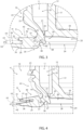
- opening device 4 may comprise:
- flow channel 11 may extend between a pouring outlet 13 (of collar 10) configured to allow for the outpouring of the pourable product and an inlet 14 (of collar 10) configured to allow for the introduction of the pourable product into flow channel 11, in particular from the inner space of package 1, in particular main body 2, into flow channel 11.
- collar 10 may extend along a central axis E and pouring outlet 13 and inlet 14 may be arranged at respective axial ends of collar 10.
- collar 10 may comprise a first delimiting rim 15 delimiting pouring outlet 13 and a second delimiting rim delimiting inlet 14, each one being arranged at the respective axial end of collar 10.
- closing element 12 may be coaxially positioned with respect to collar 10.
- a central axis F of closing element 12 may be coaxial to central axis E.
- opening device 4 may also comprise an annular interface 16 interposed between base frame 9 and collar 10 and/or connecting base frame 9 and collar 10 with one another.
- annular interface 16 may be defined by a portion of opening device 4 being interposed between base frame 9 and collar 10.
- annular interface 16 may be defined by a portion of opening device 4 which is interposed between base frame 9 and collar 10 and which comes along with a minimum thickness.
- base frame 9, collar 10 and closing element 12 may be realized in a single piece.
- opening device 4 may also comprise a closure coupled and/or couplable to collar 10 and configured to selectively open and close pouring outlet 13, in particular for respectively allowing and impeding an outpouring of the pourable product.
- closing element 12 and the closure may be connected, in particular fixed, to one another such that any movement of the closure results in a concurrent movement of closing element 12.
- closing element 12 and the closure may be connected to one another by means of fusing and/or welding and/or bonding and/or molding.
- closing element 12 may comprise a coupling membrane 20 being detachably and/or rupturably fixed to collar 10 along an (annular) initial contact portion 21 (of an inner wall 22 of collar 10).
- closing element 12 may be configured to (rupturably) detach from initial contact portion 21 so as to free and/or open the designated pour opening for allowing the outpouring of the pourable product.
- closing element 12 may be configured to seal the designated pour opening and the inner space. Afterwards, it may be possible to place closing element 12 such that closing element 12 may close the designated pour opening, but may not seal the designated pour opening and the inner space anymore.
- closing element 12 may be controllable between an active position in which closing element 12 is configured to cover and/or close the designated pour opening and an inactive position in which closing element 12 frees and/or opens the designated pour opening.
- closing element 12 may be configured to interrupt and/or at least obstacle a fluidic connection between pouring outlet 13 and inlet 14 when being in the active position and to allow for a fluidic connection between pouring outlet 13 and inlet 14 when being in the inactive position.
- closing element 12 may be arranged within flow channel 11 and/or may be interposed between pouring outlet 13 and base frame 9 when being in the active position.
- initially closing element 12 is controlled in the active position and prior to the first-time movement from the active position to the inactive position, closing element 12 is rupturably connected to initial contact portion 21 so as to also seal the designated pour opening.
- closing element 12 can be newly placed in the active position. Then, closing element 12 can newly contact collar 10, in particular inner wall 22, so as to close and/or cover the designated pour opening and/or to interrupt and/or obstacle the fluidic connection between pouring outlet 13 and inlet 14.
- collar 10 may comprise:
- sealing ring 24 may be designed such to ensure that closing element 12 closes the designated pour opening and/or interrupts and/or at least obstacles the fluidic connection between inlet 14 and pouring outlet 13 when being in the active position and after the first-time movement of closing element 12 from the active position to the inactive position. In particular, even if the exact position of at least a portion of closing element 12 is below initial contact portion 21, it is ensured that closing element 12 contacts inner wall 22 of collar 10.
- main portion 23 may comprise a first surface portion 25 of inner wall 22 and sealing ring 24 may comprise a second surface portion of inner wall 22.
- sealing ring 24 may comprise a (curved) tip portion delimiting inlet 14 and/or defining the second delimiting rim.
- inlet 14 may be arranged at an axial end of sealing ring 24 opposite to an axial end of sealing ring 24 that is arranged at initial contact portion 21.
- sealing ring 24 may be connected to and may protrude from main portion 23 in such a manner so as to extend towards and/or into the inner space of package 1. In other words, sealing ring 24 may be designed to protrude towards and/or into the inner space.
- Sealing ring 24 may delimit an auxiliary space, in particular having a frustoconical shape. More specifically, the auxiliary space may taper from (substantially) initial contact portion 21 to inlet 14.
- sealing ring 24 may present rotational symmetry with respect to central axis E.
- sealing ring 24 may comprise a first inner surface 26, in particular having an annular shape, facing flow channel 11 and an outer surface 27, in particular having an annular shape, opposite to first inner surface 26.
- first inner surface 26 may delimit the auxiliary space.
- first inner surface 26 may define the second surface portion of inner wall 22.
- outer surface 27 may face base frame 9.
- sealing ring 24 may also comprise a curved tip surface 28 connecting first inner surface 26 and outer surface 27 with one another.
- base frame 9 may comprise a first contact surface 29, in particular having an annular shape, configured to contact and/or contacting first face 7 and a second contact surface 30, in particular having an annular shape, configured to contact and/or contacting second face 8.
- first contact surface 29 and second contact surface 30 may face one another. Even more particular, first contact surface 29 and second contact surface 30 may define an interspace within which packaging material 3 is and/or is to be placed.
- first contact surface 29 and second contact surface 30 may extend within respectively a first plane H1 and a second plane H2, in particular parallel to one another.
- first contact surface 29, in particular also first plane H1, and second contact surface 30, in particular second plane H2, are spaced apart from one another by a distance d1.
- distance d1 substantially corresponds to a thickness of packaging material 3.
- initial contact portion 21 may be interposed between first contact surface 29 and pouring outlet 13.
- a thickness d2 of annular interface 16 is larger than distance d1.
- thickness d2 is at least 1,2 times, in particular at least 1,3 times, even more particular at least 1,4 times, larger than distance d1.
- base frame 9 may comprise a first annular frame 35 having first contact surface 29 and a second annular frame 36 having second contact surface 30.
- first annular frame 35 and second annular frame 36 may be integrally connected to one another.
- first annular frame 35 and second annular frame 36 may be configured to be placed respectively outside of and inside of the inner space of main body 2.
- base frame 9 may also comprise an annular coupling portion 37 integrally connected to first annular frame 36 and second annular frame 35.
- annular coupling portion 37 is arranged radially inside with respect to first annular frame 35 and second annular frame 36.
- first annular frame 35 and second annular frame 36 may radially protrude from annular coupling portion 37.
- annular interface 16 is interposed between annular coupling portion 37 and collar 10.
- base frame 9, in particular annular coupling portion 37, may comprise a second inner surface 38 facing flow channel 11 and/or outer surface 27.
- sealing ring 24 may be placed within a space delimited by second inner surface 38.
- base frame 9 may comprise an inlet aperture 39 for the pourable product.
- inlet 14 may be axially displaced from inlet aperture 39.
- inlet 14 may be interposed between initial connecting portion 21 and inlet aperture 39.
- first frame 35 may comprise a plurality of radially protruding ridge elements 40, in particular each ridge element 40 may comprise a free peripheral portion 41 (i.e free peripheral portions 41 are not interconnected with respect to one another).
- ridge elements 40 may be angularly spaced apart from one another about central axis E and/or central axis F.
- one or more ridge elements 40 may carry a respective portion of first contact surface 29, i.e. first contact surface 29 comprises a plurality of discrete portions or, in even other words, first contact surface 29 is not continuous.
- first frame 35 may comprise an external surface 42 opposite to first contact surface 29, and in particular extending within a third plane H3.
- third plane H3 may be parallel to first plane H1 and/or second plane H2.
- external surface 42 may have a planar shape.
- collar 10 may comprise a further outer surface 43, in particular opposite to inner wall 22, having a curved portion 44.
- curved portion 44 may contact and/or intersect with external surface 42.
- second inner surface 38 intersects outer surface 27 at a circumferential curve 46.
- inner surface 38 comprises circumferential curve 46.
- circumferential curve 46 may result from the intersection of an intersection plane perpendicular to central axis E with second inner surface 38.
- thickness d2 may correspond to the minimum distance between curved surface 44 and second inner surface 38.
- thickness d2 may correspond to the minimum distance between curved surface 44 and circumferential curve 46.
- annular interface 16 may extend between curved surface 44 and circumferential curve 46.
- a cross-section profile of sealing ring 24 with respect to a cross-section plane containing central axis E of collar 10 may comprise a first linear line and a second linear line radially displaced from the first linear line and being arranged radially outside with respect to the first linear line, in particular with respect to central axis E.
- the first linear line and the second linear line may result from the intersection of the cross-section plane with respectively first inner surface 26 and outer surface 27.
- the second linear line may present an extension corresponding to at least 50% of an extension of the first linear line.
- the extension of the first linear line is larger than the extension of the second linear line.
- the cross-section profile may also comprise a curved line connecting the first linear line and the second linear line with one another.
- closing element 12 may comprise:
- coupling structure 51 may be connected, in particular welded and/or bonded and/or fused, to the closure, in particular an inner surface of the closure.
- the closure may be moveable between:
- the closure may be reversibly moved between the closing configuration and the opening configuration.
- closing element 12 may be connected, in particular fused and/or welded and/or bonded, to the closure, in particular by means of coupling structure 51, such that movement of the closure between the closing configuration and the opening configuration may result in movement of closing element 12 between respectively the active position and the inactive position.
- base frame 9, collar 10 and closing element 12 may be integrally formed, in particular in a single piece.
- base frame 9, collar 10 and closing element 12 may be formed during a molding process, in particular during molding of opening device 4 onto the respective blank.
- closure may be coupled to collar 10 after formation of base frame 9, collar 10 and closing element 12.
- base frame 9, collar 10 and closing element 12 may define the first portion of opening device 4 and the closure may define the second portion of opening device 4.
- the closure is applied to collar 10 after molding of base frame 9, collar 10 and closing element 12, in particular about the designated pour opening.
- a user receives package 1 with the closure and closing element 12 being respectively in the closing configuration and the active position so as to respectively cover pouring outlet 13 and the designated pour opening.
- closing element 12 Prior to the first control of the closure from the closing configuration to the opening configuration and of closing element 12 from the active position to the inactive position, closing element 12, in particular through annular coupling membrane 20, is fixed to initial contact portion 21.
- the user in order to access the pourable product, needs to control the closure from the closing configuration to the opening configuration leading to a movement of closing element 12 from the active position to the inactive position and a rupturing of closing element 12, in particular of coupling membrane 20, from initial contact portion 21. This then allows the pourable product to flow from the inner space through flow channel 11 and out of flow channel 11 through pouring outlet 13.
- closing element 12 Each time closing element 12 is arranged again in the active position (by moving the closure in the closing configuration) closing element 12 covers the designated pour opening. Thereby, the presence of sealing ring 24 ensures that closing element 12 engages inner wall 22 so as to close the designated pour opening and/or to interrupt or to obstacle a fluid connection between inlet 14 and pouring outlet 13.
- number 4' indicates an alternative embodiment of an opening device according to the present invention.
- opening device 4' is similar to opening device 4, the following description is limited to the differences between them, and using the same references, where possible, for identical or corresponding parts.
- opening device 4' differs from opening device 4 in that external surface 42 is inclined with respect to first contact surface 35 and/or third plane H3 is inclined with respect to first plane H1 (i.e. third plane H3 and first plane H1 are not parallel to one another).
- opening device 4' As operation of opening device 4' is similar to operation of opening device 4, we refer to the above-provided description.
- opening device 4 and opening device 4' and/or of package 1 according to the present invention will be clear from the foregoing description.
Landscapes
- Engineering & Computer Science (AREA)
- Mechanical Engineering (AREA)
- Manufacturing & Machinery (AREA)
- Closures For Containers (AREA)
Applications Claiming Priority (1)
| Application Number | Priority Date | Filing Date | Title |
|---|---|---|---|
| EP21200035 | 2021-09-30 |
Publications (3)
| Publication Number | Publication Date |
|---|---|
| EP4159633A1 true EP4159633A1 (de) | 2023-04-05 |
| EP4159633C0 EP4159633C0 (de) | 2024-03-06 |
| EP4159633B1 EP4159633B1 (de) | 2024-03-06 |
Family
ID=78087022
Family Applications (1)
| Application Number | Title | Priority Date | Filing Date |
|---|---|---|---|
| EP22196513.0A Active EP4159633B1 (de) | 2021-09-30 | 2022-09-20 | Öffnungsvorrichtung für eine verpackung und verpackung mit einer öffnungsvorrichtung |
Country Status (3)
| Country | Link |
|---|---|
| EP (1) | EP4159633B1 (de) |
| CN (1) | CN118019694A (de) |
| WO (1) | WO2023052184A1 (de) |
Families Citing this family (1)
| Publication number | Priority date | Publication date | Assignee | Title |
|---|---|---|---|---|
| CN117886023B (zh) * | 2024-03-14 | 2024-05-14 | 乐美包装(昆山)有限公司 | 在片状包装材料上注塑成型的可封口装置 |
Citations (6)
| Publication number | Priority date | Publication date | Assignee | Title |
|---|---|---|---|---|
| US5176300A (en) * | 1989-12-28 | 1993-01-05 | Toppan Printing Co., Ltd. | Pouring plug for liquid paper-containers |
| US20020033395A1 (en) * | 2000-09-21 | 2002-03-21 | Shikoku Kakoki Co., Ltd. | Containers having spout and process for producing same |
| SE526048C2 (sv) * | 2003-01-10 | 2005-06-21 | Tetra Laval Holdings & Finance | Förpackningsbehållare med formsprutad öppningsanordning |
| EP2368807A1 (de) * | 2010-03-25 | 2011-09-28 | Procap France SAS | Verschlussvorrichtung für quaderförmige Verpackungen |
| EP3153413A1 (de) * | 2015-10-05 | 2017-04-12 | Tetra Laval Holdings & Finance S.A. | Verfahren und aufbringungskopf zum aufbringen eines deckels auf einen behälter |
| JP2018172136A (ja) * | 2017-03-31 | 2018-11-08 | 凸版印刷株式会社 | 口栓および無菌充填液体用容器 |
-
2022
- 2022-09-20 EP EP22196513.0A patent/EP4159633B1/de active Active
- 2022-09-20 CN CN202280065144.8A patent/CN118019694A/zh active Pending
- 2022-09-20 WO PCT/EP2022/076025 patent/WO2023052184A1/en unknown
Patent Citations (6)
| Publication number | Priority date | Publication date | Assignee | Title |
|---|---|---|---|---|
| US5176300A (en) * | 1989-12-28 | 1993-01-05 | Toppan Printing Co., Ltd. | Pouring plug for liquid paper-containers |
| US20020033395A1 (en) * | 2000-09-21 | 2002-03-21 | Shikoku Kakoki Co., Ltd. | Containers having spout and process for producing same |
| SE526048C2 (sv) * | 2003-01-10 | 2005-06-21 | Tetra Laval Holdings & Finance | Förpackningsbehållare med formsprutad öppningsanordning |
| EP2368807A1 (de) * | 2010-03-25 | 2011-09-28 | Procap France SAS | Verschlussvorrichtung für quaderförmige Verpackungen |
| EP3153413A1 (de) * | 2015-10-05 | 2017-04-12 | Tetra Laval Holdings & Finance S.A. | Verfahren und aufbringungskopf zum aufbringen eines deckels auf einen behälter |
| JP2018172136A (ja) * | 2017-03-31 | 2018-11-08 | 凸版印刷株式会社 | 口栓および無菌充填液体用容器 |
Also Published As
| Publication number | Publication date |
|---|---|
| EP4159633C0 (de) | 2024-03-06 |
| EP4159633B1 (de) | 2024-03-06 |
| WO2023052184A1 (en) | 2023-04-06 |
| CN118019694A (zh) | 2024-05-10 |
Similar Documents
| Publication | Publication Date | Title |
|---|---|---|
| EP3919404B1 (de) | Deckel-ausguss-anordnung für eine verpackung, verpackung mit einer deckel-ausguss-anordnung und verfahren zum formen einer deckel-ausguss-anordnung | |
| EP4159633A1 (de) | Öffnungsvorrichtung für eine verpackung, form zum formen einer öffnungsvorrichtung für eine verpackung und verpackung mit einer öffnungsvorrichtung | |
| EP3892562A1 (de) | Deckelanordnung für eine verpackung, deckelausgussgruppe für eine verpackung und verpackung mit der deckelausgussgruppe | |
| EP3892559B1 (de) | Deckel/ausguss-anordnung für eine verpackung und verpackung damit | |
| US20230137895A1 (en) | Spout for a package, lid-spout assembly for a package and package having a spout | |
| US20230127158A1 (en) | Spout for a package, lid-spout assembly for a package and package having a spout | |
| EP3892560A1 (de) | Deckelausgussanordnung für eine verpackung und verpackung mit einer deckelausgussanordnung | |
| EP4159631B1 (de) | Öffnungsvorrichtung für eine verpackung, form zum formen einer öffnungsvorrichtung für eine verpackung und verpackung mit einer öffnungsvorrichtung | |
| EP4159632A1 (de) | Öffnungsvorrichtung für eine verpackung, form zum formen einer öffnungsvorrichtung für eine verpackung und verpackung mit einer öffnungsvorrichtung | |
| EP4177181A1 (de) | Öffnungsvorrichtung für eine verpackung und verpackung mit einer öffnungsvorrichtung | |
| EP4159402B1 (de) | Öffnungsvorrichtung für eine verpackung, form zum formen einer öffnungsvorrichtung für eine verpackung und verpackung mit einer öffnungsvorrichtung | |
| EP4159634B1 (de) | Öffnungsvorrichtung für eine verpackung, form zum formen einer öffnungsvorrichtung für eine verpackung und verpackung mit einer öffnungsvorrichtung | |
| EP4238880A1 (de) | Deckelanordnung für eine verpackung, deckelausgussgruppe für eine verpackung und verpackung mit einer deckelausgussgruppe | |
| EP4124584A1 (de) | Öffnungsvorrichtung für eine verpackung und verpackung mit einer öffnungsvorrichtung | |
| US20230182972A1 (en) | Lid-spout assembly for a package and package having a lid-spout assembly | |
| EP4079652B1 (de) | Öffnungsvorrichtung für eine verpackung und verpackung mit einer öffnungsvorrichtung | |
| US20230406578A1 (en) | Lid-spout assembly for a package and package having a lid-spout assembly |
Legal Events
| Date | Code | Title | Description |
|---|---|---|---|
| PUAI | Public reference made under article 153(3) epc to a published international application that has entered the european phase |
Free format text: ORIGINAL CODE: 0009012 |
|
| STAA | Information on the status of an ep patent application or granted ep patent |
Free format text: STATUS: THE APPLICATION HAS BEEN PUBLISHED |
|
| AK | Designated contracting states |
Kind code of ref document: A1 Designated state(s): AL AT BE BG CH CY CZ DE DK EE ES FI FR GB GR HR HU IE IS IT LI LT LU LV MC MK MT NL NO PL PT RO RS SE SI SK SM TR |
|
| STAA | Information on the status of an ep patent application or granted ep patent |
Free format text: STATUS: REQUEST FOR EXAMINATION WAS MADE |
|
| 17P | Request for examination filed |
Effective date: 20231005 |
|
| RBV | Designated contracting states (corrected) |
Designated state(s): AL AT BE BG CH CY CZ DE DK EE ES FI FR GB GR HR HU IE IS IT LI LT LU LV MC MK MT NL NO PL PT RO RS SE SI SK SM TR |
|
| GRAP | Despatch of communication of intention to grant a patent |
Free format text: ORIGINAL CODE: EPIDOSNIGR1 |
|
| STAA | Information on the status of an ep patent application or granted ep patent |
Free format text: STATUS: GRANT OF PATENT IS INTENDED |
|
| INTG | Intention to grant announced |
Effective date: 20231215 |
|
| GRAS | Grant fee paid |
Free format text: ORIGINAL CODE: EPIDOSNIGR3 |
|
| GRAA | (expected) grant |
Free format text: ORIGINAL CODE: 0009210 |
|
| STAA | Information on the status of an ep patent application or granted ep patent |
Free format text: STATUS: THE PATENT HAS BEEN GRANTED |
|
| AK | Designated contracting states |
Kind code of ref document: B1 Designated state(s): AL AT BE BG CH CY CZ DE DK EE ES FI FR GB GR HR HU IE IS IT LI LT LU LV MC MK MT NL NO PL PT RO RS SE SI SK SM TR |
|
| REG | Reference to a national code |
Ref country code: CH Ref legal event code: EP |
|
| REG | Reference to a national code |
Ref country code: DE Ref legal event code: R096 Ref document number: 602022002252 Country of ref document: DE |
|
| REG | Reference to a national code |
Ref country code: IE Ref legal event code: FG4D |
|
| U01 | Request for unitary effect filed |
Effective date: 20240314 |
|
| U07 | Unitary effect registered |
Designated state(s): AT BE BG DE DK EE FI FR IT LT LU LV MT NL PT SE SI Effective date: 20240322 |