EP4159623A1 - Contactless power supply and data communication device, particularly for an aircraft - Google Patents
Contactless power supply and data communication device, particularly for an aircraft Download PDFInfo
- Publication number
- EP4159623A1 EP4159623A1 EP22196492.7A EP22196492A EP4159623A1 EP 4159623 A1 EP4159623 A1 EP 4159623A1 EP 22196492 A EP22196492 A EP 22196492A EP 4159623 A1 EP4159623 A1 EP 4159623A1
- Authority
- EP
- European Patent Office
- Prior art keywords
- aircraft
- communication
- induction
- power supply
- data
- Prior art date
- Legal status (The legal status is an assumption and is not a legal conclusion. Google has not performed a legal analysis and makes no representation as to the accuracy of the status listed.)
- Pending
Links
- 238000004891 communication Methods 0.000 title claims abstract description 101
- 230000006698 induction Effects 0.000 claims abstract description 52
- 230000005540 biological transmission Effects 0.000 claims description 63
- 108091008695 photoreceptors Proteins 0.000 claims description 9
- 238000013523 data management Methods 0.000 claims description 5
- 238000009434 installation Methods 0.000 abstract description 7
- 238000012986 modification Methods 0.000 abstract description 4
- 230000004048 modification Effects 0.000 abstract description 4
- 230000001939 inductive effect Effects 0.000 abstract description 2
- 230000008901 benefit Effects 0.000 description 2
- 238000005516 engineering process Methods 0.000 description 2
- 239000003292 glue Substances 0.000 description 2
- 239000000463 material Substances 0.000 description 2
- 239000004033 plastic Substances 0.000 description 2
- 241001080024 Telles Species 0.000 description 1
- 230000000712 assembly Effects 0.000 description 1
- 238000000429 assembly Methods 0.000 description 1
- 230000002457 bidirectional effect Effects 0.000 description 1
- 238000005034 decoration Methods 0.000 description 1
- 238000010586 diagram Methods 0.000 description 1
- 230000000694 effects Effects 0.000 description 1
- 238000007726 management method Methods 0.000 description 1
- 230000003287 optical effect Effects 0.000 description 1
- 230000008054 signal transmission Effects 0.000 description 1
- 229920001169 thermoplastic Polymers 0.000 description 1
Images


Classifications
-
- H—ELECTRICITY
- H02—GENERATION; CONVERSION OR DISTRIBUTION OF ELECTRIC POWER
- H02J—CIRCUIT ARRANGEMENTS OR SYSTEMS FOR SUPPLYING OR DISTRIBUTING ELECTRIC POWER; SYSTEMS FOR STORING ELECTRIC ENERGY
- H02J50/00—Circuit arrangements or systems for wireless supply or distribution of electric power
- H02J50/10—Circuit arrangements or systems for wireless supply or distribution of electric power using inductive coupling
-
- B—PERFORMING OPERATIONS; TRANSPORTING
- B64—AIRCRAFT; AVIATION; COSMONAUTICS
- B64D—EQUIPMENT FOR FITTING IN OR TO AIRCRAFT; FLIGHT SUITS; PARACHUTES; ARRANGEMENTS OR MOUNTING OF POWER PLANTS OR PROPULSION TRANSMISSIONS IN AIRCRAFT
- B64D11/00—Passenger or crew accommodation; Flight-deck installations not otherwise provided for
- B64D11/0015—Arrangements for entertainment or communications, e.g. radio, television
-
- B—PERFORMING OPERATIONS; TRANSPORTING
- B64—AIRCRAFT; AVIATION; COSMONAUTICS
- B64D—EQUIPMENT FOR FITTING IN OR TO AIRCRAFT; FLIGHT SUITS; PARACHUTES; ARRANGEMENTS OR MOUNTING OF POWER PLANTS OR PROPULSION TRANSMISSIONS IN AIRCRAFT
- B64D11/00—Passenger or crew accommodation; Flight-deck installations not otherwise provided for
- B64D11/06—Arrangements of seats, or adaptations or details specially adapted for aircraft seats
- B64D11/0624—Arrangements of electrical connectors, e.g. for earphone, internet or electric supply
-
- H—ELECTRICITY
- H04—ELECTRIC COMMUNICATION TECHNIQUE
- H04B—TRANSMISSION
- H04B10/00—Transmission systems employing electromagnetic waves other than radio-waves, e.g. infrared, visible or ultraviolet light, or employing corpuscular radiation, e.g. quantum communication
- H04B10/11—Arrangements specific to free-space transmission, i.e. transmission through air or vacuum
- H04B10/114—Indoor or close-range type systems
- H04B10/1149—Arrangements for indoor wireless networking of information
-
- H—ELECTRICITY
- H04—ELECTRIC COMMUNICATION TECHNIQUE
- H04B—TRANSMISSION
- H04B10/00—Transmission systems employing electromagnetic waves other than radio-waves, e.g. infrared, visible or ultraviolet light, or employing corpuscular radiation, e.g. quantum communication
- H04B10/11—Arrangements specific to free-space transmission, i.e. transmission through air or vacuum
- H04B10/114—Indoor or close-range type systems
- H04B10/116—Visible light communication
-
- B—PERFORMING OPERATIONS; TRANSPORTING
- B64—AIRCRAFT; AVIATION; COSMONAUTICS
- B64D—EQUIPMENT FOR FITTING IN OR TO AIRCRAFT; FLIGHT SUITS; PARACHUTES; ARRANGEMENTS OR MOUNTING OF POWER PLANTS OR PROPULSION TRANSMISSIONS IN AIRCRAFT
- B64D2221/00—Electric power distribution systems onboard aircraft
Definitions
- the present invention relates to a data communication and power supply device, in particular for an aircraft and in particular for seats of the aircraft, as well as an aircraft provided with such a device.
- the seats of an aircraft are generally provided with several accessories intended for the comfort of the passengers, for the communication of information or else for safety.
- the seats of a transport aircraft are generally provided with multifunction screens, in particular for entertainment or the transmission of information, and sockets for connecting electronic devices.
- the development of intelligent and connected seats in aircraft has the effect of multiplying the number of these accessories.
- cable harnesses are generally installed in the floor of the aircraft and the accessories of the seats are linked to these harnesses for the electrical power supply and the connection to a data communication network of the aircraft.
- the object of the present invention is to propose a solution making it possible to remedy the aforementioned drawback.
- a data communication and power supply device in particular for an aircraft and in particular for seats of the aircraft.
- a data communication and electrical power supply device which is contactless, said device making it possible in particular to communicate data by visible light and to transmit an electrical power supply by induction to aircraft seats.
- Such a device therefore does not require a harness passing through the floor of the aircraft. This simplifies the installation of the data communication and electrical power supply device and facilitates a reconfiguration of a cabin of the aircraft, comprising a modification of the position of at least some of the seats, since the seats are no longer physically tied to harnesses.
- At least one of said first and second communication units includes at least one light-emitting microdiode and at least one photoreceptor.
- the device comprises at least one chute intended to be arranged on a wall of the aircraft, and said chute is configured to be able to receive a plurality of first transmission modules, each of said transmission modules having in particular a size and a shape such that it can be introduced (mounted) in the trunking.
- the trunking comprises a plurality of connectors arranged along said trunking, each connector being configured so that at least one first transmission module can be connected to it.
- the device comprises at least one cover provided with at least one translucent zone, and configured to be able to be mounted on the trunking.
- the cover is configured to be mounted on the trunking by clips.
- the device comprises at least one protection element configured to prevent access to a space located between the first transmission module and the second transmission module.
- the present invention also relates to a data communication and power supply system for an aircraft.
- the present invention also relates to an aircraft, in particular a transport aircraft, comprising at least one data communication and power supply device, such as that described above, and/or at least one data communication and power supply, such as that described above.
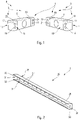
- the device 1, according to the invention and one embodiment of which is shown schematically in the figure 1 is a contactless power supply and data communication device.
- This device 1 is intended to be arranged in an aircraft in order to transmit data as well as electrical energy to equipment of said aircraft, in particular to equipment mounted on seats, in particular on passenger seats of a passenger plane. transportation.
- the device 1 can be adapted to any type of vehicle comprising equipment requiring electrical power and data transmission.
- data communication via “visible light” or via “light signals” refers to all wireless communication technologies based on the use of visible light, namely wavelength between 480nm and 650nm, also called “VLC” (for "Visible Light Communication” in English).
- VLC visible Light Communication
- the communication units 2 and 3 communicate data via the “Li-Fi” technology (for “Light Fidelity” in English) which uses the coding and the exchange of data by light amplitude modulation.
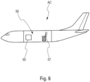
- the device 1 is configured to allow transmission of data and electrical power from a wall of the aircraft AC ( figure 6 ) to at least one seat of said aircraft AC.
- the communication unit 2 and the induction transmitter 4 are arranged in a wall 6 ( figure 4 ) of the aircraft and the communication unit 3 and the induction receiver 5 are arranged in a seat 7A ( figure 4 ) of said aircraft.
- the communication units 2 and 3 each comprise at least one transmission component and/or at least one reception component so as to be able to exchange data bidirectionally, that is to say in both directions, from communication unit 2 to communication unit 3 and from communication unit 3 to communication unit 2.
- the transmitting component corresponds to a micro light-emitting diode (often abbreviated as micro LED or in micro LED for "micro Light Emitting Diode” in English) which is able to be modulated at very high frequency
- the reception component corresponds to a photoreceptor able to pick up the modulated signals generated by the light-emitting microdiode.
- the term “microdiode” will be used alone to refer to such a light-emitting microdiode.
- the induction transmitter 4 and the induction receiver 5 each comprise a coil, preferably a flexible coil. These coils are capable of transmitting, in the usual way, electrical power by induction from the induction transmitter 4 to the induction receiver 5.
- the communication units 2 and 3 are arranged so as to be able to communicate, in the usual way, data via light signals. It is considered that said communication units 2 and 3 are able to communicate between them when they are arranged face to face and that at least one of the transmission components of one of the communication units is facing one of the reception components of the other communication unit. Preferably, the distance between the communication units 2 and 3 is of the order of a few centimeters.
- the induction transmitter 4 and the induction receiver 5 are arranged so that the induction transmitter 4 can transmit, in the usual way, electrical power by induction to the induction receiver 5.
- the induction transmitter 4 is arranged facing the induction receiver 5, at a distance of a few centimeters at most.
- the device 1 comprises a first transmission module 8 corresponding to a (single) structural block (that is to say to a single piece).
- This first transmission module 8 comprises the communication unit 2 and the induction transmitter 4.
- the device 1 comprises a second transmission module 9 also corresponding to a (single) structural block (i.e. say to one piece).
- This second transmission module 9 comprises the communication unit 3 and the induction receiver 5.
- the transmission modules 8 and 9 can, for example, correspond to boxes configured to receive at least one communication unit 2 or 3 (which can be identical), as well as either an induction transmitter 4 or an induction receiver 5.
- the transmission modules 8 and 9 have the shape of a rectangular parallelepiped.
- Each of said transmission modules 8 and 9 is provided with a so-called “front” face and a so-called “rear” face.
- the transmission module 8 is provided with a front face 10 and a rear face 11, and the transmission module 9 is provided with a front face 12 and a rear face 13.
- the front faces 10 and 12 are the faces intended to be arranged facing each other, while the rear faces 11 and 13 are the faces intended to be fixed, respectively, to the wall 6 and the seat 7.
- the rear faces 11 and 13 are , in particular, intended to make it possible to interface between the transmission modules 8 and 9 and the systems of the aircraft, as specified below.
- the wall 6 comprises an added element capable of receiving the transmission module 8.
- this added element corresponds to a chute as described below.
- the transmission module 8 is fixed directly to the wall 6 by means of fixing elements, for example by glue or screws.
- the transmission module 8 can be embedded in a housing provided for this purpose in the wall 6.
- the transmission module 9 is fixed to the seat 7A by means of a fixing element, for example by glue or screws.
- a fixing element for example by glue or screws.
- it can be integrated directly into the seat 7, for example thanks to a housing provided for this purpose in which it is mounted.
- the communication unit 2 comprises a microdiode 14 and a photoreceiver 15, and the communication unit 3 comprises a microdiode 16 and a photoreceiver 17. Furthermore, said communication units 2 and 3 are configured so that the microdiode 14 is capable of transmitting data in the form of light signals to the photoreceptor 17, which the latter is capable of detecting. Similarly, the microdiode 16 is capable of transmitting data in the form of light signals to the photoreceptor 15, which the latter is capable of detecting.
- the communication units 2 and 3 each comprise a plurality of microdiodes as well as a plurality of photoreceptors. Furthermore, each microdiode of a communication unit 2, 3 is capable of transmitting signals to at least one photoreceiver of the other communication unit. Conversely, each photoreceiver of a communication unit is capable of detecting signals emitted by at least one of the microdiodes of the other communication unit.
- the communication units 2 and 3 can each comprise a plurality of assemblies each comprising at least one microdiode and at least one photoreceptor.
- the communication unit 2 comprises a first assembly 18 comprising the microdiode 14 and the photoreceiver 15, and a second assembly 19 comprising a microdiode 20 and a photoreceiver 21.
- the communication unit 3 also comprises a first assembly 22 comprising the microdiode 16 and the photoreceptor 17, and a second assembly 23 comprising a microdiode 25 and a photoreceptor 24.
- sets 18 and 22 and sets 19 and 23 can be used differently.
- the sets 18 and 22 are intended for the operation of the communication units 2 and 3 in a usual context, while the sets 19 and 23 are intended for a redundancy function.
- the sets 18 and 22 operate, ie exchange data, while sets 19 and 23 are on standby, ie are powered but do not exchange data.
- the sets 19 and 23 are put into operation.
- Such an implementation makes it possible to avoid a cut in communications in the event of a failure of this type.
- sets 18 and 22 and sets 19 and 23 operate simultaneously.
- Such an implementation makes it possible to communicate a large quantity of data rapidly.
- this implementation is used occasionally to optimize the speed of data transmission. For example, in a normal regime, only sets 18 and 22 work and in a particular regime requiring the transfer of a large quantity of data, sets 19 and 23 are put into operation, in parallel with sets 18 and 22, in order to be able to communicate more data quickly.
- each module 8 and 9 may comprise a single connector grouping together the functions of data transmission and electrical energy or several separate connectors, in particular a connector for the transmission of data and a connector for the transmission of electrical energy.
- the device 1 comprises a chute 26 represented on the figure 2 , which is arranged on the wall 6 of the aircraft, as specified below.
- This chute 26 is configured to be able to receive a plurality of transmission modules 8.
- each of the transmission modules 8 has in particular a size and a shape such that it can be introduced (mounted) in the chute 26.
- the chute 26 can be an element attached and fixed to a surface of the wall 6 or an element arranged in a housing provided for this purpose, for example by being screwed or glued thereto.
- the trunking 26 is provided with holes 27, for example round, configured to leave access to the connectors of the wall 6 so that the connectors of the transmission modules 8 can be connected thereto.
- This chute 26 can be made of different materials, and preferably of plastic.
- the chute 26 corresponds to a rectilinear elongated element having a profile, namely a cross section, in the shape of a square "U" (that is to say whose bottom is not curved but straight), open at its longitudinal ends.
- the chute 26 has a bottom 28, lateral sides 29 and 30 and an open face 31.
- the open face 31 has two edges 32 and 33 corresponding to orthogonal extensions of the lateral sides 29 and 30, said edges 32 and 33 forming between them an opening 34.
- the opening 34 has a rectangular shape extending over the entire length of the chute 26 and it opens out at the longitudinal ends of said chute 26.
- the bottom 28 of the chute 26 has an outer face 35 (namely oriented towards the outside of the "U" shape) which may include fixing elements in order to fix said bottom 28 on the wall 6, for example by face or bonding.
- the bottom 28 also includes the holes 27 which are through holes allowing the transmission modules 8 to be connected to the connectors (not shown) of the wall 6.
- device 1 comprises at least one cover 36 ( picture 3 ) intended to be arranged on the chute 26 ( figure 2 ).
- the cover 36 is provided with at least one translucent zone able to let the light signals emitted by the communication units 2 and 3 pass so that said communication units 2 and 3 can exchange data via these light signals.
- cover 36 may also be transparent, at least in part.
- the cover 36 is intended to be arranged on the chute 26 by clips 40.
- the cover 36 corresponds to an elongated plate 37, preferably thin (of the order of a millimeter), of the same length as the chute 26 and provided, on one of its faces, with a flat surface 38, and on its opposite face, with a surface 39 provided with two clips 40.
- the surface 38 is intended to be oriented towards the outside of the chute 26 while surface 39 is intended to be oriented towards the inside of chute 26, cover 36 being fixed to chute 26 by means of clips 40.
- the clips 40 correspond to two shapes extruded over the entire length of the cover 36. These shapes are substantially orthogonal to the plate 37 of the cover 36.
- the clips 40 are provided, at their free ends, with hook shapes 41 capable of to cooperate elastically with the edges 32 and 33 of the open face 31 of the chute 26 so as to be able to easily mount and dismount the cover 36.
- the cover 36 can be fixed on the chute 26 in a different way, for example by being slid into a rail (not shown) arranged along said chute 26.
- the device 1 may comprise a plurality of covers 36.
- it may comprise shorter covers 36 and distributed over the entire length of the chute 26, each of these caches 36 being individually removable.
- the plate 37 of the cover 36 is made of a translucent material, for example a thermoplastic polymer, capable of allowing the transmission of light signals, in particular between the communication modules 8 and 9.
- the cover 36 can also comprise an opaque plate 37 provided with a plurality of translucent (or transparent) zones, which are provided at the level of the arrangement of the transmission modules 8 and 9.
- At least a part of the surface 38 of the cover 36 can comprise information, for example inscriptions or decorations in the form of messages glued, drawn or engraved.
- the device 1 may comprise another cover (not shown) intended to be arranged on the seat 7A at the level of the transmission module 9 and having for example characteristics similar to those of the cover 36.
- the device 1 comprises a protection element (not shown) intended to prevent access to the space situated between the transmission modules 8 and 9 and thus to avoid a disturbance or an impediment to the transmission of signals.
- the protection element is intended to be arranged between the wall 6 and the seat 7A and preferably has a narrow and elongated shape so as to be able to be inserted between the wall 6 and the seat 7A, and to cover all or part the length of the chute 26.
- the protection element is removably fixed by usual fixing means.
- the protection element can correspond to a rigid tablet, for example made of plastic, or to a flexible sheath, for example made of rubber.
- the protection element corresponds to an extension of at least one of the lateral sides 29 and 30 of the chute 26 ( picture 2 ). This extension extends from the chute 26 towards the seat 7A and therefore makes it possible to prevent access to the space situated between the transmission modules 8 and 9.
- the protection element can also be fixed to the seat 7A.
- the wall 6 of the aircraft is composed of a plurality of wall sections assembled together. Each of these wall sections corresponds to a panel 45 able to be juxtaposed and assembled with other similar panels in order to form the wall 6.
- the panel 45 comprises an upper part 46, provided with portholes 47, and a lower part 48.
- the chute 26 has the same length as the panel 45 and it is arranged at the level of the interface between the upper part 46 and the lower part 48 of said panel 45.
- chute 26 is configured so that when the panels are assembled to form wall 6, it is aligned with the chutes of adjacent panels.
- the device 1 as described above is part of a data communication and power supply system 50 intended to be integrated into an AC aircraft ( figure 6 ), and which comprises at least one such device 1.
- the system 50 comprises a plurality of devices 1, as well as a data management unit 51 and a power supply unit 52.
- the data management unit 51 is configured to manage the communication of data from the communication units 2 and 3 of devices 1
- the power supply unit 52 is configured to supply electric power to the inductive emitters 4 of devices 1.
- the system 50 comprises connections 53 arranged in the wall 6 and allowing the data management unit 51 to be connected to the communication units 2 via the connectors (not shown) of the wall 6.
- the links 53 correspond to usual cables for data communication, for example Ethernet or optical cables.
- the system 50 also includes connections 54 arranged in the wall 6 and allowing the electrical power management unit 52 to be connected to the induction transmitters 4 via connectors (not shown) of the wall 6.
- the links 54 correspond to usual electric cables for the electric power supply.
- the system 50 is intended to equip a cabin 55 of an aircraft, part of which has been shown on the figure 4 , in order to communicate data to the seats of said cabin 55 and supply them with electrical energy.
- the cabin 55 corresponds to at least a part of the cockpit of the aircraft, preferably a part intended to receive passengers, and it comprises in particular a floor 56, at least one wall 6 and at least one row of seats 57 comprising a seat 7A arranged along the wall 6 and at least one other said auxiliary seat 7B.
- the row of seats 57 comprises two auxiliary seats 7B and one seat 7A.
- These seats 7A and 7B are linked together in the usual way in order to form the row of seats 57 and more particularly, they have the usual connections and links between them making it possible to communicate data and a power supply between each of the seats 7A and 7B of the row of seats 57.
- This data communication and this power supply are carried out from the seat closest to the wall 6, namely the seat 7A which is the seat intended to include the transmission module 9, to the seats 7B.
- the seat 7A and 7B it is bidirectional.
- the system 50 offers great flexibility for its installation and that of the rows of seats.
- the system 50 is particularly suitable for a reconfiguration of the cabin 55 comprising a modification of the location of at least one row of seats 57.
- the devices 1 of the system 50 make it possible to communicate data and to transmit electrical energy between the walls 6 and the rows of seats 57 without contact, namely without physical connection between them.
- the transmission modules 8, arranged in the walls 6, can be moved in order to be positioned at desired positions along said walls 6. Consequently, it is possible to move rows of seats 57 along the longitudinal direction X-X of the cabin 55, in one direction or the other, and to easily adapt the position of the associated transmission modules 8, to the new positions of the rows of seats 57.
Abstract
- Le dispositif (1) comprend au moins une unité de communication (2) agencée dans une paroi de l'aéronef et au moins une unité de communication (3) agencée dans un siège de l'aéronef, qui sont aptes à coopérer ensemble afin de communiquer des données par lumière visible, ainsi qu'au moins un émetteur à induction (4) agencé dans la paroi et au moins un récepteur à induction (5) agencé dans le siège, qui sont aptes à coopérer ensemble afin de transmettre une alimentation électrique par induction, les unités de communication (2, 3) et les émetteur et récepteur à induction (4, 5) permettant d'obtenir une communication de données par la lumière visible et une alimentation électrique par induction entre la paroi et le siège de l'aéronef qui ne nécessitent pas de harnais de câbles passant par le plancher de l'aéronef, simplifient la mise en place du dispositif (1) et facilitent une modification de la position du siège.- The device (1) comprises at least one communication unit (2) arranged in a wall of the aircraft and at least one communication unit (3) arranged in a seat of the aircraft, which are capable of cooperating together in order to to communicate data by visible light, as well as at least one induction transmitter (4) arranged in the wall and at least one induction receiver (5) arranged in the seat, which are capable of cooperating together in order to transmit a power supply electric by induction, the communication units (2, 3) and the inductive transmitter and receiver (4, 5) making it possible to obtain data communication by visible light and power supply by induction between the wall and the seat of the aircraft which do not require cable harnesses passing through the floor of the aircraft, simplify the installation of the device (1) and facilitate a modification of the position of the seat.
Description
La présente invention concerne un dispositif de communication de données et d'alimentation électrique, en particulier pour un aéronef et notamment pour des sièges de l'aéronef, ainsi qu'un aéronef pourvu d'un tel dispositif.The present invention relates to a data communication and power supply device, in particular for an aircraft and in particular for seats of the aircraft, as well as an aircraft provided with such a device.
Les sièges d'un aéronef, en particulier les sièges des passagers d'un avion de transport, sont généralement munis de plusieurs accessoires destinés au confort des passagers, à la communication d'informations ou encore à la sécurité. En particulier, les sièges d'un avion de transport sont, en général, pourvus d'écrans multifonction, notamment pour le divertissement ou la transmission d'informations, et de prises pour brancher des appareils électroniques. Par ailleurs, le développement de sièges intelligents et connectés dans les aéronefs a pour conséquence de multiplier le nombre de ces accessoires.The seats of an aircraft, in particular the seats of the passengers of a transport airplane, are generally provided with several accessories intended for the comfort of the passengers, for the communication of information or else for safety. In particular, the seats of a transport aircraft are generally provided with multifunction screens, in particular for entertainment or the transmission of information, and sockets for connecting electronic devices. In addition, the development of intelligent and connected seats in aircraft has the effect of multiplying the number of these accessories.
Afin de fonctionner, la plupart de ces accessoires ont besoin d'être alimentés en énergie et d'échanger des données avec des systèmes de l'aéronef. A cet effet, des harnais de câbles sont généralement installés dans le plancher de l'aéronef et les accessoires des sièges sont liés à ces harnais pour l'alimentation électrique et la connexion à un réseau de communication de données de l'aéronef.In order to operate, most of these accessories need to be powered and to exchange data with aircraft systems. For this purpose, cable harnesses are generally installed in the floor of the aircraft and the accessories of the seats are linked to these harnesses for the electrical power supply and the connection to a data communication network of the aircraft.
Cette solution n'est pas complètement satisfaisante puisqu'elle nécessite une installation de harnais dans le plancher de l'aéronef, qui est complexe et coûteuse. De plus, une telle installation rend difficile une reconfiguration d'une cabine d'un aéronef, comprenant une modification de la position d'au moins certains des sièges.This solution is not completely satisfactory since it requires the installation of harnesses in the floor of the aircraft, which is complex and costly. Moreover, such an installation makes it difficult to reconfigure an aircraft cabin, including a modification of the position of at least some of the seats.
La présente invention a pour objet de proposer une solution permettant de remédier à l'inconvénient précité.The object of the present invention is to propose a solution making it possible to remedy the aforementioned drawback.
Pour ce faire, elle concerne un dispositif de communication de données et d'alimentation électrique, en particulier pour un aéronef et notamment pour des sièges de l'aéronef.To do this, it relates to a data communication and power supply device, in particular for an aircraft and in particular for seats of the aircraft.
Selon l'invention, le dispositif comporte au moins :
- une première unité de communication destinée à être agencée dans une paroi de l'aéronef et une seconde unité de communication destinée à être agencée dans un siège, lesdites première et seconde unités de communication étant aptes à coopérer ensemble afin de communiquer des données par lumière visible ; et
- un émetteur à induction destiné à être agencé dans une paroi de l'aéronef et un récepteur à induction destiné à être agencé dans un siège, ledit émetteur et ledit récepteur étant aptes à coopérer ensemble afin de transmettre une alimentation électrique par induction.
- a first communication unit intended to be arranged in a wall of the aircraft and a second communication unit intended to be arranged in a seat, said first and second communication units being capable of cooperating together in order to communicate data by visible light ; And
- an induction transmitter intended to be arranged in a wall of the aircraft and an induction receiver intended to be arranged in a seat, said transmitter and said receiver being capable of cooperating together in order to transmit an electrical power supply by induction.
Ainsi, grâce à l'invention, on dispose d'un dispositif de communication de données et d'alimentation électrique qui est sans contact, ledit dispositif permettant notamment de communiquer des données par la lumière visible et de transmettre une alimentation électrique par induction à des sièges d'un aéronef. Un tel dispositif ne nécessite donc pas de harnais passant par le plancher de l'aéronef. Ceci simplifie la mise en place du dispositif de communication de données et d'alimentation électrique et facilite une reconfiguration d'une cabine de l'aéronef, comprenant une modification de la position d'au moins certains des sièges, puisque les sièges ne sont plus liés physiquement à des harnais.Thus, thanks to the invention, there is a data communication and electrical power supply device which is contactless, said device making it possible in particular to communicate data by visible light and to transmit an electrical power supply by induction to aircraft seats. Such a device therefore does not require a harness passing through the floor of the aircraft. This simplifies the installation of the data communication and electrical power supply device and facilitates a reconfiguration of a cabin of the aircraft, comprising a modification of the position of at least some of the seats, since the seats are no longer physically tied to harnesses.
De plus, avantageusement, le dispositif comporte :
- un premier module de transmission correspondant à un bloc structurel et comprenant la première unité de communication et l'émetteur à induction ; et
- un second module de transmission correspondant à un bloc structurel et comprenant la seconde unité de communication et le récepteur à induction.
- a first transmission module corresponding to a structural block and comprising the first communication unit and the induction transmitter; And
- a second transmission module corresponding to a structural block and comprising the second communication unit and the induction receiver.
En outre, au moins l'une desdites première et seconde unités de communication comporte au moins une microdiode électroluminescente et au moins un photorécepteur.Further, at least one of said first and second communication units includes at least one light-emitting microdiode and at least one photoreceptor.
Dans un mode de réalisation particulier, le dispositif comporte au moins une goulotte destinée à être agencée sur une paroi de l'aéronef, et ladite goulotte est configurée pour pouvoir recevoir une pluralité de premiers modules de transmission, chacun desdits modules de transmission présentant notamment une taille et une forme telles qu'il puisse être introduit (monté) dans la goulotte.In a particular embodiment, the device comprises at least one chute intended to be arranged on a wall of the aircraft, and said chute is configured to be able to receive a plurality of first transmission modules, each of said transmission modules having in particular a size and a shape such that it can be introduced (mounted) in the trunking.
Avantageusement, la goulotte comporte une pluralité de connecteurs agencés le long de ladite goulotte, chaque connecteur étant configuré pour qu'au moins un premier module de transmission puisse y être connecté.Advantageously, the trunking comprises a plurality of connectors arranged along said trunking, each connector being configured so that at least one first transmission module can be connected to it.
De plus, le dispositif comporte au moins un cache pourvu d'au moins une zone translucide, et configuré pour pouvoir être monté sur la goulotte. Dans un mode de réalisation préféré, le cache est configuré pour être monté sur la goulotte par des clips.In addition, the device comprises at least one cover provided with at least one translucent zone, and configured to be able to be mounted on the trunking. In a preferred embodiment, the cover is configured to be mounted on the trunking by clips.
Par ailleurs, le dispositif comporte au moins un élément de protection configuré pour empêcher un accès à un espace situé entre le premier module de transmission et le second module de transmission.Furthermore, the device comprises at least one protection element configured to prevent access to a space located between the first transmission module and the second transmission module.
La présente invention concerne également un système de communication de données et d'alimentation électrique pour un aéronef.The present invention also relates to a data communication and power supply system for an aircraft.
Selon l'invention, le système comporte:
- au moins un dispositif de communication de données et d'alimentation électrique ;
- au moins une unité de gestion de données apte à gérer la communication des données des unités de communication ; et
- au moins une unité d'alimentation électrique apte à fournir une énergie électrique au ou aux émetteurs à induction.
- at least one data communication and power supply device;
- at least one data management unit capable of managing the communication of data from the communication units; And
- at least one electrical power supply unit capable of supplying electrical energy to the induction transmitter or transmitters.
La présente invention concerne également un aéronef, en particulier un avion de transport, comportant au moins un dispositif de communication de données et d'alimentation électrique, tel que celui décrit ci-dessus, et/ou au moins un système de communication de données et d'alimentation électrique, tel que celui décrit ci-dessus.The present invention also relates to an aircraft, in particular a transport aircraft, comprising at least one data communication and power supply device, such as that described above, and/or at least one data communication and power supply, such as that described above.
Les figures annexées feront bien comprendre comment l'invention peut être réalisée. Sur ces figures, des références identiques désignent des éléments semblables.
- La
figure 1 est une vue, en perspective, d'un premier module de transmission et d'un second module de transmission d'un dispositif de communication de données et d'alimentation électrique. - La
figure 2 est une vue en perspective d'une goulotte destinée à recevoir un premier module de transmission. - La
figure 3 est une vue en perspective d'un cache pourvu de clips, qui est destiné à être agencé sur la goulotte de lafigure 2 . - La
figure 4 est une vue en perspective d'une partie d'une cabine d'un aéronef comprenant une rangée de sièges et une paroi, pourvue d'un dispositif de communication de données et d'alimentation électrique. - La
figure 5 est un schéma synoptique d'un mode de réalisation particulier d'un système de communication de données et d'alimentation électrique de l'aéronef. - La
figure 6 est une vue schématique d'un aéronef comportant un système de communication de données et d'alimentation électrique.
- There
figure 1 is a perspective view of a first transmission module and a second transmission module of a data communication and power supply device. - There
figure 2 is a perspective view of a chute intended to receive a first transmission module. - There
picture 3picture 2 - There
figure 4 is a perspective view of part of an aircraft cabin comprising a row of seats and a wall, provided with a data communication and electrical power supply device. - There
figure 5 is a block diagram of a particular embodiment of a data communication and electrical power supply system of the aircraft. - There
figure 6 is a schematic view of an aircraft including a data communication and power supply system.
Le dispositif 1, selon l'invention et dont une forme de réalisation est représentée schématiquement sur la
A cet effet, le dispositif 1 comporte au moins :
- une première unité de
communication 2 et une seconde unité decommunication 3 aptes à coopérer ensemble afin de communiquer des données, sans fil, via la lumière visible ; et - un émetteur à
induction 4 et un récepteur àinduction 5 aptes à coopérer ensemble afin de transmettre une puissance électrique par induction.
- a
first communication unit 2 and asecond communication unit 3 capable of cooperating together in order to communicate data, wirelessly, via visible light; And - an
induction transmitter 4 and aninduction receiver 5 capable of cooperating together in order to transmit electrical power by induction.
Dans le cadre de la présente invention, la communication de données via « la lumière visible » ou via « des signaux lumineux » fait référence à l'ensemble des technologies de communication sans fil reposant sur l'utilisation de la lumière visible, à savoir de longueur d'onde comprise entre 480nm et 650nm, également appelées « VLC » (pour « Visible Light Communication » en anglais). De manière préférée, les unités de communication 2 et 3 communiquent des données via la technologie « Li-Fi » (pour « Light Fidelity » en anglais) qui utilise le codage et l'échange de données par modulation d'amplitude lumineuse.In the context of the present invention, data communication via "visible light" or via "light signals" refers to all wireless communication technologies based on the use of visible light, namely wavelength between 480nm and 650nm, also called "VLC" (for "Visible Light Communication" in English). Preferably, the
Le dispositif 1 est configuré pour permettre une transmission de données et d'alimentation électrique depuis une paroi de l'aéronef AC (
Les unités de communication 2 et 3 comportent, chacune, au moins un composant d'émission et/ou au moins un composant de réception de manière à pouvoir échanger des données de façon bidirectionnelle, c'est-à-dire dans les deux sens, de l'unité de communication 2 vers l'unité de communication 3 et de l'unité de communication 3 vers l'unité de communication 2. De préférence, le composant d'émission correspond à une microdiode électroluminescente (souvent abrégée en micro DEL ou en micro LED pour « micro Light Emitting Diode » en anglais) qui est apte à être modulée à très haute fréquence, et le composant de réception correspond à un photorécepteur apte à capter les signaux modulés générés par la microdiode électroluminescente. Dans le reste de la description, on utilisera le terme « microdiode » seul pour faire référence à une telle microdiode électroluminescente.The
En outre, l'émetteur à induction 4 et le récepteur à induction 5 comportent chacun une bobine, de préférence une bobine flexible. Ces bobines sont aptes à transmettre, de façon usuelle, une puissance électrique par induction de l'émetteur à induction 4 vers le récepteur à induction 5.Furthermore, the
Les unités de communication 2 et 3 sont agencées de manière à pouvoir communiquer, de façon usuelle, des données via des signaux lumineux. On considère que lesdites unités de communication 2 et 3 sont aptes à communiquer entre elles lorsqu'elles sont disposées face à face et qu'au moins l'un des composants d'émission de l'une des unités de communication est en regard de l'un des composants de réception de l'autre unité de communication. De préférence, la distance entre les unités de communication 2 et 3 est de l'ordre de quelques centimètres.The
De même, l'émetteur à induction 4 et le récepteur à induction 5 sont agencés de sorte que l'émetteur à induction 4 puisse transmettre, de façon usuelle, une puissance électrique par induction au récepteur à induction 5. Pour ce faire, l'émetteur à induction 4 est agencé en regard du récepteur à induction 5, à une distance de quelques centimètres au maximum.Similarly, the
Dans un mode de réalisation préféré, représenté sur la
Les modules de transmission 8 et 9 peuvent, par exemple, correspondre à des boîtiers configurés pour recevoir au moins une unité de communication 2 ou 3 (qui peuvent être identiques), ainsi que soit un émetteur à induction 4 soit un récepteur à induction 5.The
De plus, le module de transmission 8 est agencé dans la paroi 6 de l'aéronef, comme représenté sur la
- les unités de
communication 2et 3 sont aptes à échanger des données ; et - l'émetteur à
induction 4 est apte à transmettre de l'énergie au récepteur àinduction 5 pour une alimentation électrique.
- the
communication units - the
induction transmitter 4 is capable of transmitting energy to theinduction receiver 5 for a power supply.
Dans le mode de réalisation particulier représenté sur la
Par ailleurs, dans un mode de réalisation préféré, la paroi 6 comporte un élément rapporté apte à recevoir le module de transmission 8. De préférence, cet élément rapporté correspond à une goulotte telle que décrite ci-après. Toutefois, dans un autre mode de réalisation (non représenté), le module de transmission 8 est fixé directement sur la paroi 6 au moyen d'éléments de fixation, par exemple par de la colle ou des vis. Dans une variante de réalisation (non représentée), le module de transmission 8 peut être encastré dans un logement prévu à cet effet dans la paroi 6.Furthermore, in a preferred embodiment, the
En outre, dans un mode de réalisation particulier (non représenté), le module de transmission 9 est fixé sur le siège 7A au moyen d'un élément de fixation, par exemple par de la colle ou des vis. Dans une variante de réalisation (non représentée), il peut être directement intégré dans le siège 7, par exemple grâce à un logement prévu à cet effet dans lequel il est monté.Furthermore, in a particular embodiment (not shown), the
Dans le mode de réalisation préféré, représenté sur la
Dans un mode de réalisation particulier, les unités de communication 2 et 3 comportent, chacune, une pluralité de microdiodes ainsi qu'une pluralité de photorécepteurs. En outre, chaque microdiode d'une unité de communication 2, 3 est apte à émettre des signaux à au moins un photorécepteur de l'autre unité de communication. Réciproquement, chaque photorécepteur d'une unité de communication est apte à détecter des signaux émis par au moins l'une des microdiodes de l'autre unité de communication.In a particular embodiment, the
Par ailleurs, les unités de communication 2 et 3 peuvent, chacune, comporter une pluralité d'ensembles comprenant chacun au moins une microdiode et au moins un photorécepteur.Furthermore, the
Dans le mode de réalisation représenté sur la
Dans ce mode de réalisation particulier, les ensembles 18 et 22 et les ensembles 19 et 23 peuvent être utilisés différemment.In this particular embodiment, sets 18 and 22 and sets 19 and 23 can be used differently.
Dans une première mise en œuvre, les ensembles 18 et 22 sont destinés au fonctionnement des unités de communication 2 et 3 dans un contexte habituel, tandis que les ensembles 19 et 23 sont destinés à une fonction de redondance. Ainsi, dans un mode de fonctionnement normal, seul les ensembles 18 et 22 fonctionnent, à savoir échangent des données, tandis que les ensembles 19 et 23 sont en veille, à savoir sont alimentés mais n'échangent pas de données. Dans un mode de défaillance, c'est-à-dire dans le cas où au moins l'un des ensembles 18 ou 22 ne fonctionne pas correctement, les ensembles 19 et 23 sont mis en fonctionnement. Une telle mise en œuvre permet d'éviter une coupure des communications dans le cas d'une défaillance de ce type.In a first implementation, the
Dans une seconde mise en œuvre, les ensembles 18 et 22 et les ensembles 19 et 23 fonctionnement simultanément. Une telle mise en oeuvre permet de communiquer une grande quantité de données rapidement. Dans un mode de réalisation particulier, cette mise en œuvre est utilisée ponctuellement pour optimiser la rapidité de la transmission de données. Par exemple, dans un régime normal, seul les ensembles 18 et 22 fonctionnent et dans un régime particulier nécessitant le transfert d'une grande quantité de données, les ensembles 19 et 23 sont mis en fonctionnement, en parallèle des ensembles 18 et 22, afin de pouvoir communiquer plus de données rapidement.In a second implementation, sets 18 and 22 and sets 19 and 23 operate simultaneously. Such an implementation makes it possible to communicate a large quantity of data rapidly. In a particular embodiment, this implementation is used occasionally to optimize the speed of data transmission. For example, in a normal regime, only sets 18 and 22 work and in a particular regime requiring the transfer of a large quantity of data, sets 19 and 23 are put into operation, in parallel with
En outre, les faces arrière 11 et 13 des modules de transmission 8 et 9 sont pourvues de connecteurs (non représentés). Ces connecteurs peuvent correspondre à des éléments de connexion usuels, de type mâle ou femelle, tels que des fiches ou des prises électriques. Ils sont configurés pour pouvoir être connectés à des connecteurs coopérant qui sont prévus à cet effet dans la paroi 6 et le siège 7A de manière à permettre une transmission pour les données et l'alimentation électrique. De plus, chaque module 8 et 9 peut comporter un seul connecteur regroupant les fonctions de transmission de données et d'énergie électrique ou plusieurs connecteurs distincts, notamment un connecteur pour la transmission de données et un connecteur pour la transmission d'énergie électrique.Furthermore, the rear faces 11 and 13 of the
Par ailleurs, dans un mode de réalisation particulier, le dispositif 1 comporte une goulotte 26 représentée sur la
Dans une réalisation préférée de ce mode de réalisation particulier, représentée sur la
Le fond 28 de la goulotte 26 présente une face externe 35 (à savoir orientée vers l'extérieur de la forme en « U ») pouvant comporter des éléments de fixation afin de fixer ledit fond 28 sur la paroi 6, par exemple par visage ou collage. Le fond 28 comporte également les trous 27 qui sont des trous traversant permettant de connecter les modules de transmission 8 aux connecteurs (non représentés) de la paroi 6.The bottom 28 of the
En outre, le dispositif 1 comporte au moins un cache 36 (
Dans un mode de réalisation préféré, illustré sur la
Dans le mode de réalisation représenté sur la
Dans un autre mode de réalisation, le cache 36 peut être fixé sur la goulotte 26 d'une manière différente, par exemple en étant glissé dans un rail (non représenté) agencé le long de ladite goulotte 26.In another embodiment, the
En outre, dans un mode de réalisation particulier (non représenté), le dispositif 1 peut comporter une pluralité de caches 36. En particulier, il peut comporter des caches 36 plus courts et répartis sur toute la longueur de la goulotte 26, chacun de ces caches 36 étant démontable individuellement.In addition, in a particular embodiment (not shown), the
En outre, au moins la plaquette 37 du cache 36 est réalisée dans un matériau translucide, par exemple un polymère thermoplastique, apte à permettre la transmission de signaux lumineux, notamment entre les modules de communication 8 et 9. Cependant, le cache 36 peut également comporter une plaquette 37 opaque pourvue d'une pluralité de zones translucides (ou transparentes), qui sont prévues au niveau de l'agencement des modules de transmission 8 et 9.In addition, at least the
De plus, dans un mode de réalisation particulier, au moins une partie de la surface 38 du cache 36, destinée à être orientée vers l'extérieur, peut comporter des informations, par exemple des inscriptions ou des décorations sous forme de messages collées, dessinées ou gravées.Moreover, in a particular embodiment, at least a part of the
Dans un mode de réalisation particulier, le dispositif 1 peut comporter un autre cache (non représenté) destiné à être agencé sur le siège 7A au niveau du module de transmission 9 et présentant par exemple des caractéristiques similaires à celles du cache 36.In a particular embodiment, the
Par ailleurs, dans un mode de réalisation préféré, le dispositif 1 comporte un élément de protection (non représenté) destiné à empêcher un accès à l'espace situé entre les modules de transmission 8 et 9 et ainsi éviter une perturbation ou un empêchement de la transmission des signaux. L'élément de protection est destiné à être agencé entre la paroi 6 et le siège 7A et présente, de préférence, une forme étroite et allongée de manière à pouvoir être intercalé entre la paroi 6 et le siège 7A, et à couvrir tout ou partie de la longueur de la goulotte 26.Furthermore, in a preferred embodiment, the
De préférence, l'élément de protection est fixé de manière amovible par des moyens de fixation usuels. De façon non limitative, l'élément de protection peut correspondre à une tablette rigide, par exemple en plastique, ou à une gaine souple, par exemple en caoutchouc.Preferably, the protection element is removably fixed by usual fixing means. In a non-limiting way, the protection element can correspond to a rigid tablet, for example made of plastic, or to a flexible sheath, for example made of rubber.
Dans un mode de réalisation particulier, l'élément de protection correspond à un prolongement d'au moins l'un des côtés latéraux 29 et 30 de la goulotte 26 (
Dans un mode de réalisation particulier, représenté sur la
Dans ce mode de réalisation, le panneau 45 comporte une partie supérieure 46, pourvue de hublots 47, et une partie inférieure 48. De plus, la goulotte 26 présente la même longueur que le panneau 45 et elle est agencée au niveau de l'interface entre la partie supérieure 46 et la partie inférieure 48 dudit panneau 45.In this embodiment, the
En outre, la goulotte 26 est configurée de sorte que, lorsque les panneaux sont assemblés pour former la paroi 6, elle est alignée avec les goulottes des panneaux adjacents.Further,
Le dispositif 1 tel que décrit ci-dessus fait partie d'un système 50 de communication de données et d'alimentation électrique destiné à être intégré dans un aéronef AC (
Dans le mode de réalisation particulier représenté schématiquement sur la
Le système 50 comporte des liaisons 53 agencées dans la paroi 6 et permettant à l'unité de gestion de données 51 d'être reliée aux unités de communication 2 par l'intermédiaire des connecteurs (non représentés) de la paroi 6. Les liaisons 53 correspondent à des câbles usuels pour la communication de données, par exemple des câbles Ethernet ou optiques.The
Le système 50 comporte également des liaisons 54 agencées dans la paroi 6 et permettant à l'unité de gestion d'alimentation électrique 52 d'être reliée aux émetteurs à induction 4 par l'intermédiaire des connecteurs (non représentés) de la paroi 6. Les liaisons 54 correspondent à des câbles électriques usuels pour l'alimentation électrique.The
Dans un mode de réalisation préféré, représenté sur les
De préférence, la cabine 55 présente la configuration suivante :
- elle présente une direction longitudinale d'axe X-X ;
- elle comporte un couloir 58 rectiligne agencé au centre de la cabine 55, selon l'axe longitudinal X-X ;
- elle comporte une pluralité de rangées de sièges 57 orthogonales à l'axe X-X et agencées parallèlement entre elles, en deux colonnes de part et d'autre du couloir central 58 ;
- elle comporte deux parois 6, délimitant les côtés latéraux, à savoir de part et d'autre de l'axe X-X de la cabine 55, et contre lesquelles sont agencées les rangées de sièges 57, le siège 7A de chaque rangée de sièges 57 étant le siège accolé à l'une des deux parois 6 ; et
- elle comporte le système 50 comprenant les dispositifs 1 tels que celui décrit ci-dessus.
- it has a longitudinal direction of axis XX;
- it comprises a
rectilinear corridor 58 arranged in the center of thecabin 55, along the longitudinal axis XX; - it comprises a plurality of rows of
seats 57 orthogonal to the axis XX and arranged parallel to each other, in two columns on either side of thecentral aisle 58; - it comprises two
walls 6, delimiting the lateral sides, namely on either side of the axis XX of thecabin 55, and against which the rows ofseats 57 are arranged, theseat 7A of each row ofseats 57 being the seat attached to one of the twowalls 6; And - it comprises the
system 50 comprising thedevices 1 such as that described above.
De plus, dans ce mode de réalisation, la rangée de sièges 57 comporte deux sièges auxiliaires 7B et un siège 7A. Ces sièges 7A et 7B sont liés entre eux de manière usuelle afin de former la rangée de sièges 57 et plus particulièrement, ils présentent des connexions et des liaisons usuelles entre eux permettant de communiquer des données et une alimentation électrique entre chacun des sièges 7A et 7B de la rangée de sièges 57. Cette communication de données et cette alimentation électrique sont réalisées depuis le siège le plus proche de la paroi 6, à savoir le siège 7A qui est le siège destiné à comporter le module de transmission 9, vers les sièges 7B. Concernant la communication de données entre les sièges 7A et 7B, celle-ci est bidirectionnelle.Moreover, in this embodiment, the row of
Le système 50, tel que décrit ci-dessus, présente une grande flexibilité pour son installation et celle des rangées de sièges.The
De plus, le système 50 est particulièrement adapté à une reconfiguration de la cabine 55 comprenant une modification de l'emplacement d'au moins une rangée de sièges 57. En effet, les dispositifs 1 du système 50 permettent de communiquer des données et de transmettre de l'énergie électrique entre les parois 6 et les rangées de sièges 57 sans contact, à savoir sans liaison physique entre eux. De plus, les modules de transmission 8, agencés dans les parois 6, peuvent être déplacés afin d'être positionnés à des positions souhaitées le long desdites parois 6. Par conséquent, il est possible de déplacer des rangées de sièges 57 selon la direction longitudinale X-X de la cabine 55, dans un sens ou dans l'autre, et d'adapter aisément la position des modules de transmission 8 associés, aux nouvelles positions des rangées de sièges 57.In addition, the
Le système 50 de communication de données et d'alimentation électrique, tel que décrit ci-dessus, présente ainsi de nombreux avantages. En particulier :
- il permet de réaliser un plancher sans harnais pour la communication de données et l'alimentation électrique des sièges ;
- il permet une installation très flexible des rangées de sièges ;
- il permet de reconfigurer la cabine facilement et avec plus de flexibilité ;
- il permet de bénéficier d'une transmission de données à la fois rapide, sécurisée et sans interférences avec d'autres systèmes sans fil (Wi-Fi, Bluetooth, ...) ; et
- il évite la dépendance à d'autres types d'ondes telles que des ondes Wi-Fi.
- it makes it possible to create a harness-free floor for data communication and power supply to the seats;
- it allows a very flexible installation of the rows of seats;
- it allows the cabin to be reconfigured easily and with greater flexibility;
- it allows you to benefit from data transmission that is both fast, secure and without interference with other wireless systems (Wi-Fi, Bluetooth, etc.); And
- it avoids dependence on other types of waves such as Wi-Fi waves.
Claims (10)
caractérisé en ce qu'il comporte au moins :
characterized in that it comprises at least:
caractérisé en ce qu'il comporte :
characterized in that it comprises:
caractérisé en ce qu'au moins l'une desdites première et seconde unités de communication (2, 3) comporte au moins une microdiode électroluminescente (14, 16, 20, 25) et au moins un photorécepteur (15, 17, 21, 24).Device according to claims 1 and 2,
characterized in that at least one of said first and second communication units (2, 3) comprises at least one light-emitting microdiode (14, 16, 20, 25) and at least one photoreceptor (15, 17, 21, 24 ).
caractérisé en ce qu'il comporte au moins une goulotte (26) destinée à être agencée sur une paroi (6) de l'aéronef (AC), et en ce que ladite goulotte (26) est configurée pour pouvoir recevoir une pluralité de premiers modules de transmission (8).Device according to any one of claims 2 and 3,
characterized in that it comprises at least one chute (26) intended to be arranged on a wall (6) of the aircraft (AC), and in that said chute (26) is configured to be able to receive a plurality of first transmission modules (8).
caractérisé en ce que la goulotte (26) comporte une pluralité de connecteurs agencés le long de ladite goulotte (26), chaque connecteur étant configuré pour qu'au moins un premier module de transmission (8) puisse y être connecté.Device according to claim 4,
characterized in that the trunking (26) comprises a plurality of connectors arranged along said trunking (26), each connector being configured so that at least a first transmission module (8) can be connected thereto.
caractérisé en ce qu'il comporte au moins un cache (36) pourvu d'au moins une zone translucide, et configuré pour pouvoir être monté sur la goulotte (26).Device according to one of Claims 4 and 5,
characterized in that it comprises at least one cover (36) provided with at least one translucent zone, and configured to be able to be mounted on the trunking (26).
caractérisé en ce que le cache (36) est configuré pour être monté sur la goulotte (26) par des clips (40).Device according to claim 6,
characterized in that the cover (36) is configured to be mounted on the trunking (26) by clips (40).
caractérisé en ce qu'il comporte un élément de protection (42) configuré pour empêcher un accès à un espace situé entre le premier module de transmission (8) et le second module de transmission (9).Device according to any one of Claims 2 to 7,
characterized in that it comprises a protection element (42) configured to prevent access to a space located between the first transmission module (8) and the second transmission module (9).
caractérisé en ce qu'il comporte ;
characterized in that it comprises;
caractérisé en ce qu'il comporte au moins un dispositif (1) selon l'une quelconque des revendications 1 à 8 et/ou au moins un système (50) selon la revendication 9.Aircraft,
characterized in that it comprises at least one device (1) according to any one of Claims 1 to 8 and/or at least one system (50) according to Claim 9.
Applications Claiming Priority (1)
| Application Number | Priority Date | Filing Date | Title |
|---|---|---|---|
| FR2110261 | 2021-09-29 |
Publications (1)
| Publication Number | Publication Date |
|---|---|
| EP4159623A1 true EP4159623A1 (en) | 2023-04-05 |
Family
ID=78332955
Family Applications (1)
| Application Number | Title | Priority Date | Filing Date |
|---|---|---|---|
| EP22196492.7A Pending EP4159623A1 (en) | 2021-09-29 | 2022-09-20 | Contactless power supply and data communication device, particularly for an aircraft |
Country Status (3)
| Country | Link |
|---|---|
| US (1) | US20230099152A1 (en) |
| EP (1) | EP4159623A1 (en) |
| CN (1) | CN115871932A (en) |
Citations (4)
| Publication number | Priority date | Publication date | Assignee | Title |
|---|---|---|---|---|
| EP0718945A2 (en) * | 1992-01-17 | 1996-06-26 | The Wiremold Company | A raceway assembly |
| US20190349082A1 (en) * | 2016-11-21 | 2019-11-14 | Lufthansa Technik Ag | Two-way data communication system for aircraft cabins |
| US10494098B2 (en) * | 2017-02-16 | 2019-12-03 | Inflight Investments Inc. | Sidewall seat track mounted USB power and communication hub for passenger aircraft |
| US20200322048A1 (en) * | 2019-04-05 | 2020-10-08 | Airbus Operations Gmbh | Optical Wireless Communication Network For Aircraft |
Family Cites Families (2)
| Publication number | Priority date | Publication date | Assignee | Title |
|---|---|---|---|---|
| US5336849A (en) * | 1992-01-17 | 1994-08-09 | The Wiremold Company | Raceway assembly for power and communications conductors |
| US20140226983A1 (en) * | 2013-02-13 | 2014-08-14 | Teac Aerospace Technologies, Inc. | In-flight li-fi media distribution system |
-
2022
- 2022-09-20 EP EP22196492.7A patent/EP4159623A1/en active Pending
- 2022-09-23 US US17/951,171 patent/US20230099152A1/en active Pending
- 2022-09-29 CN CN202211197530.0A patent/CN115871932A/en active Pending
Patent Citations (4)
| Publication number | Priority date | Publication date | Assignee | Title |
|---|---|---|---|---|
| EP0718945A2 (en) * | 1992-01-17 | 1996-06-26 | The Wiremold Company | A raceway assembly |
| US20190349082A1 (en) * | 2016-11-21 | 2019-11-14 | Lufthansa Technik Ag | Two-way data communication system for aircraft cabins |
| US10494098B2 (en) * | 2017-02-16 | 2019-12-03 | Inflight Investments Inc. | Sidewall seat track mounted USB power and communication hub for passenger aircraft |
| US20200322048A1 (en) * | 2019-04-05 | 2020-10-08 | Airbus Operations Gmbh | Optical Wireless Communication Network For Aircraft |
Also Published As
| Publication number | Publication date |
|---|---|
| CN115871932A (en) | 2023-03-31 |
| US20230099152A1 (en) | 2023-03-30 |
Similar Documents
| Publication | Publication Date | Title |
|---|---|---|
| EP1166303B1 (en) | Modular electrical appliances and housing comprising same | |
| EP3267232B1 (en) | System for connecting a plurality of pins to a unitary assembly made up of an electronic equipment housing panel and a plurality of connector bases | |
| EP3520586B1 (en) | Aircraft having computers distributed in the fuselage | |
| FR3056702B1 (en) | LUMINOUS MODULE WITH INTEGRATED DRIVER | |
| EP1479194A1 (en) | Local network for data exchange between portable micro-computers of aircraft passengers | |
| EP3804280B1 (en) | System for communicating via signals of li-fi type | |
| EP1033524A2 (en) | Signalling device | |
| EP2355636B1 (en) | Device for connecting at least one electronic device in an aircraft | |
| CA1233564A (en) | Read head for deciphering marks on documents | |
| FR2791185A1 (en) | LOW VOLTAGE CONNECTOR PROVIDED WITH AN ADAPTER AND ADAPTER FOR SUCH A CONNECTOR | |
| FR3083212A1 (en) | Airplane seat, airplane seat arrangement with an airplane seat and airplane with an airplane seat arrangement | |
| FR2859330A1 (en) | MONO-TRACK COMMUNICATION DEVICE FOR OPTICAL FIBER | |
| FR3007239A1 (en) | METHOD OF INTEGRATION OF REMOVABLE INTERCONNECTION MODULE IN A FURNITURE, FURNISHED SO EQUIPPED AND AIRCRAFT HAVING A BAY CONSISTING OF SUCH FURNITURE | |
| EP2333912B1 (en) | Device for electric connection | |
| EP4159623A1 (en) | Contactless power supply and data communication device, particularly for an aircraft | |
| CA2356886C (en) | Improved system for acquiring geophysical data | |
| WO2020249592A1 (en) | Support for connecting a seat to a communication network | |
| FR2981897A1 (en) | DEVICE FOR ELECTRICALLY POWERING EQUIPMENT INTEGRATED IN THE FLOOR OF AN AIRCRAFT CABIN | |
| EP3513513A1 (en) | Light fixture that can be connected to a telecommunication network | |
| FR3078171A1 (en) | ELECTRICAL EQUIPMENT COMPRISING A FIRST PART AND A SECOND ELECTRICALLY INSULATED PART OF THE FIRST PART | |
| FR3038274A1 (en) | SYSTEM FOR ELECTRICALLY CONNECTING A CABIN EQUIPMENT FROM AN AIRCRAFT TO A CONTROL SYSTEM AND AT LEAST ONE ELECTRIC POWER SOURCE OF SAID AIRCRAFT | |
| FR3057054A1 (en) | COOLING MODULE AND ELECTRONIC UNIT COMPRISING SUCH A MODULE | |
| WO2023174798A1 (en) | Seat equipped with a data-communication module using li-fi technology | |
| EP3985865A1 (en) | Functionalised equipment with one or more functionalised covering elements | |
| FR3065131A1 (en) | CONNECTABLE LUMINAIRE AS A TELECOMMUNICATION NETWORK |
Legal Events
| Date | Code | Title | Description |
|---|---|---|---|
| PUAI | Public reference made under article 153(3) epc to a published international application that has entered the european phase |
Free format text: ORIGINAL CODE: 0009012 |
|
| STAA | Information on the status of an ep patent application or granted ep patent |
Free format text: STATUS: THE APPLICATION HAS BEEN PUBLISHED |
|
| AK | Designated contracting states |
Kind code of ref document: A1 Designated state(s): AL AT BE BG CH CY CZ DE DK EE ES FI FR GB GR HR HU IE IS IT LI LT LU LV MC MK MT NL NO PL PT RO RS SE SI SK SM TR |
|
| STAA | Information on the status of an ep patent application or granted ep patent |
Free format text: STATUS: REQUEST FOR EXAMINATION WAS MADE |
|
| 17P | Request for examination filed |
Effective date: 20231002 |
|
| RBV | Designated contracting states (corrected) |
Designated state(s): AL AT BE BG CH CY CZ DE DK EE ES FI FR GB GR HR HU IE IS IT LI LT LU LV MC MK MT NL NO PL PT RO RS SE SI SK SM TR |